EP3859091A1 - Construction machine - Google Patents
Construction machine Download PDFInfo
- Publication number
- EP3859091A1 EP3859091A1 EP19865047.5A EP19865047A EP3859091A1 EP 3859091 A1 EP3859091 A1 EP 3859091A1 EP 19865047 A EP19865047 A EP 19865047A EP 3859091 A1 EP3859091 A1 EP 3859091A1
- Authority
- EP
- European Patent Office
- Prior art keywords
- engine
- pump
- hydraulic pump
- torque
- hydraulic
- Prior art date
- Legal status (The legal status is an assumption and is not a legal conclusion. Google has not performed a legal analysis and makes no representation as to the accuracy of the status listed.)
- Granted
Links
Images










Classifications
-
- E—FIXED CONSTRUCTIONS
- E02—HYDRAULIC ENGINEERING; FOUNDATIONS; SOIL SHIFTING
- E02F—DREDGING; SOIL-SHIFTING
- E02F9/00—Component parts of dredgers or soil-shifting machines, not restricted to one of the kinds covered by groups E02F3/00 - E02F7/00
- E02F9/26—Indicating devices
-
- F—MECHANICAL ENGINEERING; LIGHTING; HEATING; WEAPONS; BLASTING
- F02—COMBUSTION ENGINES; HOT-GAS OR COMBUSTION-PRODUCT ENGINE PLANTS
- F02D—CONTROLLING COMBUSTION ENGINES
- F02D41/00—Electrical control of supply of combustible mixture or its constituents
- F02D41/22—Safety or indicating devices for abnormal conditions
-
- E—FIXED CONSTRUCTIONS
- E02—HYDRAULIC ENGINEERING; FOUNDATIONS; SOIL SHIFTING
- E02F—DREDGING; SOIL-SHIFTING
- E02F9/00—Component parts of dredgers or soil-shifting machines, not restricted to one of the kinds covered by groups E02F3/00 - E02F7/00
- E02F9/20—Drives; Control devices
- E02F9/2004—Control mechanisms, e.g. control levers
-
- E—FIXED CONSTRUCTIONS
- E02—HYDRAULIC ENGINEERING; FOUNDATIONS; SOIL SHIFTING
- E02F—DREDGING; SOIL-SHIFTING
- E02F9/00—Component parts of dredgers or soil-shifting machines, not restricted to one of the kinds covered by groups E02F3/00 - E02F7/00
- E02F9/20—Drives; Control devices
- E02F9/2058—Electric or electro-mechanical or mechanical control devices of vehicle sub-units
- E02F9/2062—Control of propulsion units
- E02F9/2066—Control of propulsion units of the type combustion engines
-
- E—FIXED CONSTRUCTIONS
- E02—HYDRAULIC ENGINEERING; FOUNDATIONS; SOIL SHIFTING
- E02F—DREDGING; SOIL-SHIFTING
- E02F9/00—Component parts of dredgers or soil-shifting machines, not restricted to one of the kinds covered by groups E02F3/00 - E02F7/00
- E02F9/20—Drives; Control devices
- E02F9/22—Hydraulic or pneumatic drives
- E02F9/2221—Control of flow rate; Load sensing arrangements
- E02F9/2232—Control of flow rate; Load sensing arrangements using one or more variable displacement pumps
- E02F9/2235—Control of flow rate; Load sensing arrangements using one or more variable displacement pumps including an electronic controller
-
- E—FIXED CONSTRUCTIONS
- E02—HYDRAULIC ENGINEERING; FOUNDATIONS; SOIL SHIFTING
- E02F—DREDGING; SOIL-SHIFTING
- E02F9/00—Component parts of dredgers or soil-shifting machines, not restricted to one of the kinds covered by groups E02F3/00 - E02F7/00
- E02F9/20—Drives; Control devices
- E02F9/22—Hydraulic or pneumatic drives
- E02F9/2246—Control of prime movers, e.g. depending on the hydraulic load of work tools
-
- E—FIXED CONSTRUCTIONS
- E02—HYDRAULIC ENGINEERING; FOUNDATIONS; SOIL SHIFTING
- E02F—DREDGING; SOIL-SHIFTING
- E02F9/00—Component parts of dredgers or soil-shifting machines, not restricted to one of the kinds covered by groups E02F3/00 - E02F7/00
- E02F9/20—Drives; Control devices
- E02F9/22—Hydraulic or pneumatic drives
- E02F9/226—Safety arrangements, e.g. hydraulic driven fans, preventing cavitation, leakage, overheating
-
- E—FIXED CONSTRUCTIONS
- E02—HYDRAULIC ENGINEERING; FOUNDATIONS; SOIL SHIFTING
- E02F—DREDGING; SOIL-SHIFTING
- E02F9/00—Component parts of dredgers or soil-shifting machines, not restricted to one of the kinds covered by groups E02F3/00 - E02F7/00
- E02F9/26—Indicating devices
- E02F9/267—Diagnosing or detecting failure of vehicles
-
- F—MECHANICAL ENGINEERING; LIGHTING; HEATING; WEAPONS; BLASTING
- F02—COMBUSTION ENGINES; HOT-GAS OR COMBUSTION-PRODUCT ENGINE PLANTS
- F02B—INTERNAL-COMBUSTION PISTON ENGINES; COMBUSTION ENGINES IN GENERAL
- F02B63/00—Adaptations of engines for driving pumps, hand-held tools or electric generators; Portable combinations of engines with engine-driven devices
- F02B63/06—Adaptations of engines for driving pumps, hand-held tools or electric generators; Portable combinations of engines with engine-driven devices for pumps
-
- F—MECHANICAL ENGINEERING; LIGHTING; HEATING; WEAPONS; BLASTING
- F02—COMBUSTION ENGINES; HOT-GAS OR COMBUSTION-PRODUCT ENGINE PLANTS
- F02D—CONTROLLING COMBUSTION ENGINES
- F02D29/00—Controlling engines, such controlling being peculiar to the devices driven thereby, the devices being other than parts or accessories essential to engine operation, e.g. controlling of engines by signals external thereto
- F02D29/02—Controlling engines, such controlling being peculiar to the devices driven thereby, the devices being other than parts or accessories essential to engine operation, e.g. controlling of engines by signals external thereto peculiar to engines driving vehicles; peculiar to engines driving variable pitch propellers
-
- F—MECHANICAL ENGINEERING; LIGHTING; HEATING; WEAPONS; BLASTING
- F02—COMBUSTION ENGINES; HOT-GAS OR COMBUSTION-PRODUCT ENGINE PLANTS
- F02D—CONTROLLING COMBUSTION ENGINES
- F02D29/00—Controlling engines, such controlling being peculiar to the devices driven thereby, the devices being other than parts or accessories essential to engine operation, e.g. controlling of engines by signals external thereto
- F02D29/04—Controlling engines, such controlling being peculiar to the devices driven thereby, the devices being other than parts or accessories essential to engine operation, e.g. controlling of engines by signals external thereto peculiar to engines driving pumps
-
- F—MECHANICAL ENGINEERING; LIGHTING; HEATING; WEAPONS; BLASTING
- F02—COMBUSTION ENGINES; HOT-GAS OR COMBUSTION-PRODUCT ENGINE PLANTS
- F02D—CONTROLLING COMBUSTION ENGINES
- F02D31/00—Use of speed-sensing governors to control combustion engines, not otherwise provided for
- F02D31/001—Electric control of rotation speed
-
- F—MECHANICAL ENGINEERING; LIGHTING; HEATING; WEAPONS; BLASTING
- F02—COMBUSTION ENGINES; HOT-GAS OR COMBUSTION-PRODUCT ENGINE PLANTS
- F02D—CONTROLLING COMBUSTION ENGINES
- F02D41/00—Electrical control of supply of combustible mixture or its constituents
- F02D41/02—Circuit arrangements for generating control signals
- F02D41/14—Introducing closed-loop corrections
- F02D41/1497—With detection of the mechanical response of the engine
-
- F—MECHANICAL ENGINEERING; LIGHTING; HEATING; WEAPONS; BLASTING
- F04—POSITIVE - DISPLACEMENT MACHINES FOR LIQUIDS; PUMPS FOR LIQUIDS OR ELASTIC FLUIDS
- F04B—POSITIVE-DISPLACEMENT MACHINES FOR LIQUIDS; PUMPS
- F04B49/00—Control, e.g. of pump delivery, or pump pressure of, or safety measures for, machines, pumps, or pumping installations, not otherwise provided for, or of interest apart from, groups F04B1/00 - F04B47/00
- F04B49/12—Control, e.g. of pump delivery, or pump pressure of, or safety measures for, machines, pumps, or pumping installations, not otherwise provided for, or of interest apart from, groups F04B1/00 - F04B47/00 by varying the length of stroke of the working members
-
- F—MECHANICAL ENGINEERING; LIGHTING; HEATING; WEAPONS; BLASTING
- F15—FLUID-PRESSURE ACTUATORS; HYDRAULICS OR PNEUMATICS IN GENERAL
- F15B—SYSTEMS ACTING BY MEANS OF FLUIDS IN GENERAL; FLUID-PRESSURE ACTUATORS, e.g. SERVOMOTORS; DETAILS OF FLUID-PRESSURE SYSTEMS, NOT OTHERWISE PROVIDED FOR
- F15B15/00—Fluid-actuated devices for displacing a member from one position to another; Gearing associated therewith
- F15B15/18—Combined units comprising both motor and pump
-
- G—PHYSICS
- G07—CHECKING-DEVICES
- G07C—TIME OR ATTENDANCE REGISTERS; REGISTERING OR INDICATING THE WORKING OF MACHINES; GENERATING RANDOM NUMBERS; VOTING OR LOTTERY APPARATUS; ARRANGEMENTS, SYSTEMS OR APPARATUS FOR CHECKING NOT PROVIDED FOR ELSEWHERE
- G07C5/00—Registering or indicating the working of vehicles
- G07C5/08—Registering or indicating performance data other than driving, working, idle, or waiting time, with or without registering driving, working, idle or waiting time
- G07C5/0808—Diagnosing performance data
-
- G—PHYSICS
- G07—CHECKING-DEVICES
- G07C—TIME OR ATTENDANCE REGISTERS; REGISTERING OR INDICATING THE WORKING OF MACHINES; GENERATING RANDOM NUMBERS; VOTING OR LOTTERY APPARATUS; ARRANGEMENTS, SYSTEMS OR APPARATUS FOR CHECKING NOT PROVIDED FOR ELSEWHERE
- G07C5/00—Registering or indicating the working of vehicles
- G07C5/08—Registering or indicating performance data other than driving, working, idle, or waiting time, with or without registering driving, working, idle or waiting time
- G07C5/0816—Indicating performance data, e.g. occurrence of a malfunction
- G07C5/0825—Indicating performance data, e.g. occurrence of a malfunction using optical means
-
- E—FIXED CONSTRUCTIONS
- E02—HYDRAULIC ENGINEERING; FOUNDATIONS; SOIL SHIFTING
- E02F—DREDGING; SOIL-SHIFTING
- E02F3/00—Dredgers; Soil-shifting machines
- E02F3/04—Dredgers; Soil-shifting machines mechanically-driven
- E02F3/28—Dredgers; Soil-shifting machines mechanically-driven with digging tools mounted on a dipper- or bucket-arm, i.e. there is either one arm or a pair of arms, e.g. dippers, buckets
- E02F3/30—Dredgers; Soil-shifting machines mechanically-driven with digging tools mounted on a dipper- or bucket-arm, i.e. there is either one arm or a pair of arms, e.g. dippers, buckets with a dipper-arm pivoted on a cantilever beam, i.e. boom
- E02F3/32—Dredgers; Soil-shifting machines mechanically-driven with digging tools mounted on a dipper- or bucket-arm, i.e. there is either one arm or a pair of arms, e.g. dippers, buckets with a dipper-arm pivoted on a cantilever beam, i.e. boom working downwardly and towards the machine, e.g. with backhoes
-
- E—FIXED CONSTRUCTIONS
- E02—HYDRAULIC ENGINEERING; FOUNDATIONS; SOIL SHIFTING
- E02F—DREDGING; SOIL-SHIFTING
- E02F3/00—Dredgers; Soil-shifting machines
- E02F3/04—Dredgers; Soil-shifting machines mechanically-driven
- E02F3/28—Dredgers; Soil-shifting machines mechanically-driven with digging tools mounted on a dipper- or bucket-arm, i.e. there is either one arm or a pair of arms, e.g. dippers, buckets
- E02F3/36—Component parts
- E02F3/42—Drives for dippers, buckets, dipper-arms or bucket-arms
- E02F3/425—Drive systems for dipper-arms, backhoes or the like
-
- E—FIXED CONSTRUCTIONS
- E02—HYDRAULIC ENGINEERING; FOUNDATIONS; SOIL SHIFTING
- E02F—DREDGING; SOIL-SHIFTING
- E02F9/00—Component parts of dredgers or soil-shifting machines, not restricted to one of the kinds covered by groups E02F3/00 - E02F7/00
- E02F9/20—Drives; Control devices
- E02F9/22—Hydraulic or pneumatic drives
- E02F9/2264—Arrangements or adaptations of elements for hydraulic drives
- E02F9/2267—Valves or distributors
-
- E—FIXED CONSTRUCTIONS
- E02—HYDRAULIC ENGINEERING; FOUNDATIONS; SOIL SHIFTING
- E02F—DREDGING; SOIL-SHIFTING
- E02F9/00—Component parts of dredgers or soil-shifting machines, not restricted to one of the kinds covered by groups E02F3/00 - E02F7/00
- E02F9/20—Drives; Control devices
- E02F9/22—Hydraulic or pneumatic drives
- E02F9/2264—Arrangements or adaptations of elements for hydraulic drives
- E02F9/2271—Actuators and supports therefor and protection therefor
-
- E—FIXED CONSTRUCTIONS
- E02—HYDRAULIC ENGINEERING; FOUNDATIONS; SOIL SHIFTING
- E02F—DREDGING; SOIL-SHIFTING
- E02F9/00—Component parts of dredgers or soil-shifting machines, not restricted to one of the kinds covered by groups E02F3/00 - E02F7/00
- E02F9/20—Drives; Control devices
- E02F9/22—Hydraulic or pneumatic drives
- E02F9/2278—Hydraulic circuits
- E02F9/2285—Pilot-operated systems
-
- E—FIXED CONSTRUCTIONS
- E02—HYDRAULIC ENGINEERING; FOUNDATIONS; SOIL SHIFTING
- E02F—DREDGING; SOIL-SHIFTING
- E02F9/00—Component parts of dredgers or soil-shifting machines, not restricted to one of the kinds covered by groups E02F3/00 - E02F7/00
- E02F9/20—Drives; Control devices
- E02F9/22—Hydraulic or pneumatic drives
- E02F9/2278—Hydraulic circuits
- E02F9/2296—Systems with a variable displacement pump
-
- F—MECHANICAL ENGINEERING; LIGHTING; HEATING; WEAPONS; BLASTING
- F02—COMBUSTION ENGINES; HOT-GAS OR COMBUSTION-PRODUCT ENGINE PLANTS
- F02D—CONTROLLING COMBUSTION ENGINES
- F02D41/00—Electrical control of supply of combustible mixture or its constituents
- F02D41/02—Circuit arrangements for generating control signals
- F02D41/14—Introducing closed-loop corrections
- F02D41/1401—Introducing closed-loop corrections characterised by the control or regulation method
- F02D2041/1413—Controller structures or design
- F02D2041/1432—Controller structures or design the system including a filter, e.g. a low pass or high pass filter
-
- F—MECHANICAL ENGINEERING; LIGHTING; HEATING; WEAPONS; BLASTING
- F02—COMBUSTION ENGINES; HOT-GAS OR COMBUSTION-PRODUCT ENGINE PLANTS
- F02D—CONTROLLING COMBUSTION ENGINES
- F02D41/00—Electrical control of supply of combustible mixture or its constituents
- F02D41/22—Safety or indicating devices for abnormal conditions
- F02D2041/228—Warning displays
-
- F—MECHANICAL ENGINEERING; LIGHTING; HEATING; WEAPONS; BLASTING
- F02—COMBUSTION ENGINES; HOT-GAS OR COMBUSTION-PRODUCT ENGINE PLANTS
- F02D—CONTROLLING COMBUSTION ENGINES
- F02D2200/00—Input parameters for engine control
- F02D2200/02—Input parameters for engine control the parameters being related to the engine
- F02D2200/10—Parameters related to the engine output, e.g. engine torque or engine speed
- F02D2200/1006—Engine torque losses, e.g. friction or pumping losses or losses caused by external loads of accessories
-
- F—MECHANICAL ENGINEERING; LIGHTING; HEATING; WEAPONS; BLASTING
- F02—COMBUSTION ENGINES; HOT-GAS OR COMBUSTION-PRODUCT ENGINE PLANTS
- F02D—CONTROLLING COMBUSTION ENGINES
- F02D2200/00—Input parameters for engine control
- F02D2200/02—Input parameters for engine control the parameters being related to the engine
- F02D2200/10—Parameters related to the engine output, e.g. engine torque or engine speed
- F02D2200/101—Engine speed
-
- F—MECHANICAL ENGINEERING; LIGHTING; HEATING; WEAPONS; BLASTING
- F02—COMBUSTION ENGINES; HOT-GAS OR COMBUSTION-PRODUCT ENGINE PLANTS
- F02D—CONTROLLING COMBUSTION ENGINES
- F02D2250/00—Engine control related to specific problems or objectives
- F02D2250/18—Control of the engine output torque
-
- F—MECHANICAL ENGINEERING; LIGHTING; HEATING; WEAPONS; BLASTING
- F02—COMBUSTION ENGINES; HOT-GAS OR COMBUSTION-PRODUCT ENGINE PLANTS
- F02D—CONTROLLING COMBUSTION ENGINES
- F02D41/00—Electrical control of supply of combustible mixture or its constituents
- F02D41/02—Circuit arrangements for generating control signals
- F02D41/021—Introducing corrections for particular conditions exterior to the engine
Definitions
- the present invention relates to a construction machine, such as a hydraulic excavator and a crane, equipped with an engine diagnosing device.
- a diesel engine (hereinafter, simply referred to as "engine”) is normally used as a power source of a hydraulic drive system.
- An abnormality in this engine leads to a reduction in output power of the engine and has a great influence such as a reduction in a performance of the construction machine and occurrence of constraints on operations; thus, it is required to detect an abnormality and ensure prevention and maintenance.
- various engine diagnosing technologies have been conventionally proposed.
- a machine body management controller collects frequency distribution information representing a relation between a signal intensity related to engine output power and an occurrence frequency whenever the machine body is actuated for a predetermined time and transmits those pieces of data to an accumulation server by a wireless communication function, and the accumulation server stores therein the data.
- a decrease in the output power of an engine is detected by arranging a plurality of pieces of accumulated frequency distribution information in time series and comparing the information, and the decrease in the engine output power is determined.
- Patent Document 1 Japanese Patent No. 4853921
- the intensity corresponding to the engine output power and the frequency information are accumulated over a given period of time and the plurality of pieces of the frequency information are compared in time series; thus, it is unnecessary to prepare thresholds for determination and it is possible to determine a degree of degradation of the engine by a degree of change in a feature variable only for the machine body.
- a load actually acting on a work device depends on a content of work; thus, strictly speaking, a difference in output power is affected by a difference in a work load. In particular, even if trying to observe an aging degradation, the contents of work over a long period of time differ in a work site and the like and are expected to naturally differ in the work load.
- a tendency of the engine output power is affected by the work site; therefore, it is considered that the tendency is not purely reflective of the performance of the engine and feature variable for determination includes large uncertainty (errors) although the tendency can be somewhat evaluated as a statistical tendency.
- Patent Document 1 not a machine-mounted controller but the accumulation server or the like is used via remote communication for the purpose of cost containment.
- this is a configuration adopted to constrain a cost of the machine-mounted controller, which can be said as a supportive background factor that to-be-processed data is enormous and it is difficult to cope with the data by a current machine-mounted controller at a machine-mounted controller technology level and a control technology levels to date.
- the accumulation server it is possible for the accumulation server to handle a huge volume of data; however, a communication cost for transfer of the large volume of data from the machine body is additionally required, and a cost for achieving a diagnosis control logic is generated again in this case.
- the present invention has been made in view of such situations, and an object of the present invention is to provide a construction machine in which a cost required to perform diagnosis of a degradation such as a reduction in output power of an engine is reduced while engine degradation diagnosis accuracy is improved.
- the present invention provides a construction machine comprising: an engine; a hydraulic system including a variable displacement hydraulic pump driven by the engine, a hydraulic actuator driven by a delivery fluid of the hydraulic pump, and a regulator that controls a displacement volume of the hydraulic pump in such a manner that an input torque of the hydraulic pump does not exceed a maximum absorption torque; a controller that computes a torque command value of speed sensing control for controlling the regulator in such a manner that the maximum absorption torque of the hydraulic pump decreases as a load torque of the hydraulic pump increases and a rotation speed of the engine decreases; and an engine diagnosing device that diagnoses the engine, wherein the engine diagnosing device includes the controller, and wherein the controller is configured to: determine whether the hydraulic pump is in a preset loaded state for acquiring diagnosis data of the engine, validate a controlled variable related to a torque command value of the speed sensing control as the diagnosis data of the engine when it is determined that the hydraulic pump is in the preset loaded state, and generate time history data using the validated controlled variable as a current
- the controller determines whether the hydraulic pump is in the preset loaded state for acquiring diagnosis data of the engine, validate a controlled variable related to a torque command value of the speed sensing control as the diagnosis data of the engine when it is determined that the hydraulic pump is in the preset loaded state, and enables the time history data to be displayed as trend data for engine diagnosis on a display device, it is possible to greatly reduce a volume of data captured into the controller as the diagnosis data of the engine, and to suppress a cost required to perform the diagnosis of the degradation such as the reduction in the output power of the engine.
- the present invention it is possible to improve the engine degradation diagnosis accuracy while suppressing the cost required to perform diagnosis of the degradation such as the reduction in the output power of the engine.
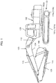
- FIG. 1 is a diagram depicting a hydraulic excavator that is a representative example of a construction machine according to the present invention.
- the hydraulic excavator includes a travel structure 101, a swing structure 102 disposed on the travel structure 101, and a front work device attached to the swing structure 102, that is, a work device 103.
- the travel structure 101 has a pair of left and right crawlers 101a and 101b (only one of which is depicted in FIG. 1 ), and the crawlers 101a and 101b are driven by travel motors 110a and 110b (only one of which is depicted), respectively and travel.
- the swing structure 102 is driven by a swing motor 102a and swings on the travel structure 101.
- the work device 103 is configured with a boom 104 attached to the swing structure 102 vertically rotatably, an arm 105 attached to the boom 104 rotatably, and a bucket 106 attached to the arm 105 rotatably.
- the boom 104 is driven by a boom cylinder 112
- the arm is driven by an arm cylinder 113
- the bucket 106 is driven by a bucket cylinder 114.
- a cabin 120 including an operation room is provided in a front side position on the swing structure 102.
- FIG. 2 is a diagram depicting an overall configuration including a hydraulic system and a control system for the hydraulic system mounted in the hydraulic excavator according to a first embodiment of the present invention.
- the hydraulic system will first be described.
- the hydraulic system mounted in the hydraulic excavator includes: a diesel engine 10 (hereinafter, simply referred to as "engine") that is a prime mover; a variable displacement hydraulic pump 12 driven by the engine 10; a control valve 16 incorporating therein a plurality of control spools controlling flows of hydraulic fluids supplied to a plurality of actuators 14 (only one of which is depicted in FIG. 2 for the sake of convenience); a main relief valve 18 that is connected to a hydraulic line of a hydraulic pump 12 and that regulates an upper limit of a pressure applied to the control valve 16 (delivery pressure of the hydraulic pump 12); a plurality of hydraulic pilot type operation devices 20 (only one of which is depicted in FIG.
- command pilot pressures operation signals
- a shuttle valve block 22 incorporating therein a plurality of shuttle valves that select a highest command pilot pressure among the command pilot pressures introduced from the plurality of operation devices 20 to the control valve 16 and that generate a pump flow rate control pressure
- a regulator 24 that controls a tilting amount (displacement volume, that is, capacity) of the hydraulic pump 12 and controls the delivery flow rate of the hydraulic pump 12.
- Each of the plurality of operation devices 20 has an operation lever 20a and generates the command pilot pressure by operator's operating the operation lever 20a, and the intended hydraulic actuator is driven by guiding this command pilot pressure to the control valve 16.
- the hydraulic excavator depicted in FIG. 1 operates under a mechanism such that the hydraulic fluid delivered from the hydraulic pump 12 is supplied to each hydraulic actuator 14 via the control valve 16 in this way.
- the regulator 24 has a pump actuator 26 that drives a displacement volume change member (for example, a swash plate) of the hydraulic pump 12, and a pump flow control valve 28 and a pump torque control valve 30 that control a hydraulic pressure introduced to the pump actuator 26 and that control a tilting amount of the hydraulic pump 12.
- a displacement volume change member for example, a swash plate
- a pump flow control valve 28 and a pump torque control valve 30 that control a hydraulic pressure introduced to the pump actuator 26 and that control a tilting amount of the hydraulic pump 12.
- the control system includes: a rotary dial type target rotation speed indicating device 32 that generates an indication signal of a target rotation speed of the engine 10 by operator's operating rotation; an engine rotation sensor 33 that detects a rotation speed (an actual rotation speed) of the engine 10; a pressure sensor 21 that detects a delivery pressure of the hydraulic pump 12; a plurality of pressure sensors 35 as operation sensors (only one of which is depicted in FIG.
- a pressure sensor 36 that detects a pump flow control pressure generated by the shuttle valve block 22; a controller 37 to which the indication signal from the target rotation speed indicating device 32 and detection signals from the engine rotation sensor 33 and the pressure sensors 21, 35, and 36 are input, and which performs predetermined computing processing; a display device 38 to which a display signal from the controller 37 is input and which displays time history data (to be described later) of a feature variable; and a flow control solenoid valve 39 and a torque control solenoid valve 40 to which a command signal from the controller 37 is input and which output a flow control pressure and a torque control pressure to the pump flow control valve 28 and the pump torque control valve 30 of the regulator 24, respectively.
- FIG. 3 is a diagram depicting details of the regulator 24.
- the regulator 24 has the pump actuator 26 that drives the displacement volume change member of the hydraulic pump 12, and the pump flow control valve 28 and the pump torque control valve 30 that control a driving pressure introduced to the pump actuator 26 and that control the tilting amount of the hydraulic pump.
- the pump actuator 26 is a servo piston including an actuating piston 26a having a large-diameter pressure receiving section 26b and a small-diameter pressure receiving section 26c, a control pressure adjusted by the pump flow control valve 28 and the pump torque control valve 30 to a pressure in a range of a constant pilot pressure of a pilot pump Pp from a tank pressure is introduced to the large-diameter pressure receiving section 26b, and the constant pilot pressure of the pilot pump Pp is introduced to the small-diameter pressure receiving section 26c.
- the actuating piston 26a moves in a left direction in FIG.
- a tilting amount of the swash plate of the hydraulic pump 12 is reduced, and a pump delivery flow rate is reduced.
- the pressure introduced to the large-diameter pressure receiving section 26b decreases, then the actuating piston 26a moves in a right direction in FIG. 3 , the tilting amount of the swash plate of the hydraulic pump 12 is increased, and the pump delivery flow rate is increased.
- the pump flow control valve 28 has a pressure receiving section 28a to which the flow control pressure output from the flow control solenoid valve 39 is introduced.
- the pump flow control valve 28 controls the pump delivery flow rate in such a manner that the pump delivery flow rate is equal to a pump flow rate in response to the pump flow control pressure.
- the pump torque control valve 30 has a pressure receiving section 30a to which a delivery pressure of the hydraulic pump 12 is introduced and a pressure receiving section 30b to which the torque control pressure output from the torque control solenoid valve 40, and a spring 30c is located opposite to the pressure receiving sections 30a and 30b.
- the delivery flow rate of the hydraulic pump 12 is reduced in response to a rise of the delivery pressure of the hydraulic pump 12, thereby exercising control in such a manner that an absorption torque of the hydraulic pump 12 does not exceed a maximum torque determined by the difference value between the urging force of the spring 30c and the hydraulic force by the torque control pressure from the torque control solenoid valve 40 introduced to the pressure receiving section 30b.
- the maximum torque is variable by the torque control pressure from the torque control solenoid valve 40. This respect will be described later.
- FIG. 4 is a functional block diagram depicting a processing content of the controller 37.
- the controller 37 is configured to determine whether the hydraulic pump 12 is in a preset loaded state for acquiring diagnosis data of the engine 10, validate a controlled variable related to a torque command value of speed sensing control as the diagnosis data of the engine 10 when it is determined that the hydraulic pump 12 is in the preset loaded state, generate time history data using this validated controlled variable as a current feature variable, and enable this time history data to be displayed as trend data for engine diagnosis on the display device 38.
- the controller 37 has a flow control computing section 65 of positive pump control and a torque control computing section 66 for speed sensing control.
- the flow control computing section 65 has a demanded flow rate computing section 45 that calculates a demanded flow rate on the basis of the pump flow control pressure (highest command pilot pressure) detected by the pressure sensor 36, a target tilting amount computing section 46 that calculates a target tilting amount of the hydraulic pump 12 from the calculated demanded flow rate, and a current conversion section 47 that converts the calculated target tilting amount into a command current for the flow control solenoid valve 39 and that outputs the command current.
- a demanded flow rate computing section 45 that calculates a demanded flow rate on the basis of the pump flow control pressure (highest command pilot pressure) detected by the pressure sensor 36
- a target tilting amount computing section 46 that calculates a target tilting amount of the hydraulic pump 12 from the calculated demanded flow rate
- a current conversion section 47 that converts the calculated target tilting amount into a command current for the flow control solenoid valve 39 and that outputs the command current.
- FIG. 5 is a functional block diagram depicting computing contents of the demanded flow rate computing section 45 and the target tilting amount computing section 46.
- the demanded flow rate computing section 45 includes a table of the pump flow control pressure and the demanded flow rate set such that the demanded flow rate increases as the pump flow control pressure increase, and the demanded flow rate computing section 45 calculates a corresponding demanded flow rate by referring the pump flow control pressure detected by the pressure sensor 36 to the table.
- the target tilting amount computing section 46 includes a table of the demanded flow rate and the target tilting amount set such that the target tilting amount increases as the demanded flow rate increases, and the target tilting amount computing section 46 calculates a corresponding target tilting amount by referring the calculated demanded flow rate to the table.
- the current conversion section 47 is configured to generate a command current that is made higher as the target tilting amount is larger, the flow control solenoid valve 39 is excited by the command current and outputs the flow control pressure to the pressure receiving section 28a in the pump flow control valve 28, and the delivery flow rate of the hydraulic pump 12 is thereby controlled as previously described.
- the hydraulic pump 12 can thereby control the delivery flow rate of the hydraulic pump 12 by a scheme referred to as positive pump control to increase the delivery flow rate of the hydraulic pump 12 in response to an operation amount (demanded flow rate) of the operation lever 20a of the operation device 20.
- the current conversion section 55 is configured to output the command current that is made higher as the torque command value Ta is lower than the reference torque T0, and the torque control solenoid valve 40 is excited by the command current and outputs the torque control pressure to the pressure receiving section 30b in the pump torque control valve 30, and the maximum absorption torque of the hydraulic pump 12 is thereby controlled as described previously.
- FIG. 6 is a diagram depicting changes in torque characteristics and the maximum torque of the hydraulic pump 12 set by the torque control pressure from the torque control solenoid valve 40.
- the addition section 54 calculates the torque command value Ta equal to the reference torque T0 calculated by the reference torque computing section 53, and the torque control pressure output from the torque control solenoid valve 40 to the pressure receiving section 30b in the pump torque control valve 30 takes on a predetermined value, torque characteristics and the maximum torque of the hydraulic pump 12 set by the regulator 24 are Sa and Tmaxa, respectively.
- the torque control computing section 66 for the speed sensing control over the engine 10 is provided.
- the controller 37 further has an engine diagnosis computing section 67 that serves as an engine diagnosing device that diagnoses the engine 10.
- the engine diagnosis computing section 67 diagnoses the engine 10 by grasping the pump control state by the speed sensing control on the basis of the concept described above.
- the engine diagnosis computing section 67 has: a state determination section 56 that determines whether the hydraulic pump 12 is in the preset loaded state for acquiring the diagnosis data of the engine 10; a controlled variable computing section 57 that validates and captures the torque correction amount ⁇ Ta that is the controlled variable related to the torque command value Ta of the speed sensing control as the diagnosis data of the engine 10 when the determination result by the state determination section 56 is satisfied (is true) and when it is determined that the hydraulic pump 12 is in the preset loaded state; a filter processing section 58 that performs low-pass filter processing on this validated torque correction amount ⁇ Ta * (validated controlled variable) for stabilization; a time history data generation section 59 that uses the validated torque correction amount ⁇ Ta * (validated controlled variable) by way of the filter processing section 58 as a current feature variable, that calculates a magnitude of this feature variable and a change in this feature variable and adds time history information to this feature variable, and that generates the time history data of the feature variable for the engine
- the display device 38 has an operation section 38a and a display screen 38b, outputs a display request signal to the controller 37 by operating the operation section 38a, and displays the time history data of the feature variable for the predetermined period acquired from the storage device 60 via the display computing section 61 in the controller 37 as the trend data for the engine diagnosis on the display screen 38b.
- the controlled variable may be other than ⁇ Ta as long as the controlled variable is related to the torque command value Ta of the speed sensing control.
- the correction amount computing section 52 is a proportional element computing section, a similar effect can be obtained even using a rotation speed deviation ⁇ N input from the previous stage and different by a proportional coefficient multiple as the controlled variable.
- the torque command value Ta of the speed sensing control may be used as the controlled variable per se.
- the display device 38 is not limited to the display device provided in the hydraulic excavator but may be a display device provided outside of the hydraulic excavator such as that provided in an administrative room. In that case, information may be exchanged via wireless communication means.
- the state determination section 56 validates the torque correction value ⁇ Ta as the engine diagnosis data while limiting the preset loaded state of the hydraulic pump 12 for acquiring the diagnosis data of the engine 10 to a specific operation scene of the hydraulic system that satisfies a diagnosis condition for the engine 10.
- the specific operation scene of the hydraulic system that satisfies the diagnosis condition for the engine 10 means herein an operation scene where the load torque (absorption torque) of the hydraulic pump 12 is in a stable state.
- the boom 104 is raised to set the boom cylinder 112 into a stroke end state, the operation lever 20a of the boom operation device 20 is fully operated, the delivery pressure of the hydraulic pump 12 is raised up to a set pressure of the main relief valve 18, and the main relief valve 18 is set into a relief state.
- the delivery flow rate and the delivery pressure of the hydraulic pump 12 are kept at certain values; thus, it is possible to easily estimate the loaded state of the hydraulic pump 12.
- the state determination section 56 estimates such a loaded state of the hydraulic pump 12 (loaded state in which the delivery pressure of the hydraulic pump 12 is constant to be equal to the relief pressure of the main relief valve 18, and in which the tilting amount of the hydraulic pump 12 is constant) as the specific operation scene that satisfies the diagnosis condition for the engine 10, and validates the torque correction amount ⁇ Ta to the torque correction amount ⁇ Ta * while limiting the preset loaded state of the hydraulic pump 12 to such an operation scene.
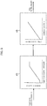
- FIG. 7A is a flowchart depicting a processing content of the state determination section 56.
- the state determination section 56 determines whether the operation device 20 is fully operated in a boom raising direction and the main relief valve 18 is in the relief state on the basis of the operation signal for boom raising of the operation device 20 detected by the pressure sensor 35 (operation sensor) and the delivery pressure of the hydraulic pump 12 detected by the pressure sensor 21 (Steps S100 and S110), and determines that the hydraulic system is in the specific operation scene and the hydraulic pump 12 is in the preset loaded state when the operation device 20 is fully operated in the boom raising direction and the main relief valve 18 is in the relief state, and then outputs a valid operation flag (Step S120).
- FIG. 7B is a functional block diagram depicting the processing content of the state determination section 56.
- the state determination section 56 causes a comparison section 61b to compare the operation signal (command pilot pressure) indicating boom raising of the operation device 20 detected by the pressure sensor 35 (operation sensor) with an operation signal (command pilot pressure) indicating a boom fully raising operation and preset to a setting section 61a, and determines whether the operation signal indicating the boom raising is equal to or greater than the operation signal indicating the boom fully raising operation. Furthermore, the state determination section 56 causes a comparison section 62b to compare the delivery pressure of the hydraulic pump 12 detected by the pressure sensor 21 with the set pressure of the main relief valve 18 preset to a setting section 62a, and determines whether the delivery pressure of the hydraulic pump 12 is equal to or higher than the set pressure of the main relief valve 18.
- Step S120 When the operation signal indicating the boom raising is equal to or greater than the operation signal indicating the boom fully raising operation and the delivery pressure of the hydraulic pump 12 is equal to or higher than the set pressure of the main relief valve 18 (when AND conditions are satisfied), the state determination section 56 determines that the hydraulic system is in the specific operation scene described above, and outputs the valid operation flag (Step S120).
- This valid operation flag serves as a flag it is determined that the hydraulic pump 12 is in the preset loaded state for acquiring the diagnosis data of the engine 10.
- the specific operation scene is determined by detecting that the operation lever 20a is fully operated.
- the tilting amount of the hydraulic pump 12 can be directly grasped, the tilting amount may be directly calculated and evaluated as an alternative to detecting that the operation lever 20a is fully operated.
- the controller 37 performs the following computing.
- a case in which the specific operation scene satisfying the diagnosis condition for the engine 10 is the scene where the operation lever is fully operated for the boom raising and the delivery pressure of the hydraulic pump 12 is equal to the relief pressure, will be described herein.
- the state determination section 56 acquires the operation signal (command pilot pressure) indicating the boom raising from the detection signal of the pressure sensor 35, causes the comparison section 61b to compare the acquired operation signal indicating the boom raising with the preset operation signal indicating the boom fully raising operation, and determines whether the operation signal indicating the boom raising is equal to or greater than the operation signal indicating the boom fully raising operation. Furthermore, the state determination section 56 acquires the delivery pressure of the hydraulic pump 12 from the detection signal of the pressure sensor 21, causes the comparison section 62b to compare the acquired delivery pressure with the set pressure of the main relief valve 18, and determines whether the delivery pressure of the hydraulic pump 12 is equal to or higher than the set pressure of the main relief valve 18. When the AND conditions are satisfied in these two comparison sections 61b and 62b, the state determination section 56 determines that the hydraulic pump 12 is in the preset loaded state for acquiring the diagnosis data of the engine 10, and the valid operation flag indicates a true value.
- the state determination section 56 determines that the hydraulic pump 12 is in the preset loaded state for acquiring the diagnosis data of
- This valid operation flag and the torque correction amount ⁇ Ta are input to the controlled variable computing section 57, and the controlled variable computing section 57 validates the torque correction amount ⁇ Ta and captures the torque correction amount ⁇ Ta*.
- the filter processing section 58 performs the low-pass filter processing on this validated torque correction amount ⁇ Ta * over a valid section to obtain a stabilized quantity of state. This quantity of state is the feature variable at a current time.
- the time history data generation section 59 calculates the magnitude of this feature variable and the change in this feature variable and adds the time history information to the feature variable, generates the time history data of the feature variable for the engine diagnosis, and stores the generated time history data in the storage device 60.
- time history data of the feature variable referred herein is calculated in sequence online, it is possible to reduce a memory area used by the storage device 60 by reducing the time history data to the number of times of sampling necessary for display as the time history data. For example, since even data acquired one piece per hour, one piece per day, or the like can often sufficiently express a tendency of a failure or a degradation to grasp the failure or the degradation, it is possible to minimize information to be handled by decimating the time history data to sampling data sufficient to express the tendency.
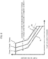
- FIG. 8 is a diagram depicting an example of the trend data for the engine diagnosis displayed on the display screen 38b of the display device 38.
- a confirming person such as the operator or a maintenance person can determine a degree of the degradation of the engine 10.
- the controller 37 determines whether the hydraulic pump 12 is in the preset loaded state, and validates the controlled variable (for example, the torque correction value ⁇ Ta) related to the torque command value Ta of the speed sending control as the diagnosis data of the engine 10 and enables the controlled variable to be displayed as the trend data for the engine diagnosis when it is determined that the hydraulic pump 12 is in the preset loaded state; thus, it is thereby possible to greatly reduce the volume of data captured in the controller 37 as the diagnosis data of the engine 10 and suppress a cost required to perform diagnosis of the degradation such as the reduction in the output power of the engine 10.
- the controlled variable for example, the torque correction value ⁇ Ta
- the time history data for the engine diagnosis is generated as the diagnosis data of the engine 10 by validating the controlled variable related to the torque command value Ta of the speed sensing control when the hydraulic pump 12 is in the preset loaded state (operation scene where the load torque of the hydraulic pump 12 is in the stable state), it is possible to suppress diagnosis noise based on a measurement error or the like, accurately grasp a situation of the reduction in the output power of the engine 10, and improve accuracy of the diagnosis of the engine degradation as depicted in FIG. 8 .
- the state determination section 56 limits the "preset loaded state" of the hydraulic pump 12 for acquiring the diagnosis data of the engine 10 to the specific operation scene of the hydraulic system that satisfies the diagnosis condition for the engine 10; thus, it is possible to accurately grasp the loaded state of the hydraulic pump 12. Owing to this, it is possible to suppress the diagnosis noise and accurately grasp the situation of the reduction in the output power of the engine 10.
- the "preset loaded state" of the hydraulic pump 12 for acquiring the diagnosis data of the engine 10 is limited to the specific operation scene, it is estimated that an occurrence frequency of such a limited operation scene is low depending on an environment such as a manner of operator's operation and a content of work, a constraint on a site, and the like, the operation scene for acquiring the diagnosis data is rare depending on situations, and it is impossible to provide good-quality diagnosis.
- the second embodiment is intended to improve the respects and to be capable of sufficiently acquiring the diagnosis data of the engine 10. Details of the second embodiment will be described hereinafter. The same parts as those in the first embodiment are denoted by the same reference characters and description thereof is omitted.
- the tilting amount of the hydraulic pump 12 can be calculated within the controller 37 since the tilting amount of the hydraulic pump 12 is controlled by the controller 37. Furthermore, the delivery pressure of the hydraulic pump 12 is detected by the pressure sensor 21 and available within the controller 37. It is, therefore, possible to calculate the loaded state of the hydraulic pump 12 using the pump tilting amount and the pump delivery pressure.
- FIG. 10 is a functional block diagram depicting a processing content of a controller 37A according to the second embodiment of the present invention.
- an engine diagnosis computing section (engine diagnosing device) 67A differs from the engine diagnosis computing section 67 according to the first embodiment in that the engine diagnosis computing section 67A further includes a pump tilting amount computing section 64 and the target tilting amount calculated by the target tilting amount computing section 46 is input to a state determination section 56A as an alternative to the detection signal (boom raising command) of the pressure sensor 35.
- FIG. 11A is a flowchart depicting processing contents of the pump tilting amount computing section 64 and the state determination section 56A.
- the controller 37A causes the pump tilting amount computing section 64 to calculate a current tilting amount of the hydraulic pump 12 on the basis of the torque command value Ta calculated by the torque control computing section 66 for the speed sensing control, the delivery pressure of the hydraulic pump 12 detected by the pressure sensor 21, and the target tilting amount calculated by the flow control computing section 65 for the positive pump control (Step S200).
- the controller 37A causes the state determination section 56A to calculate the load torque of the hydraulic pump 12 using the pump tilting amount calculated by the pump tilting amount computing section 64 and the delivery pressure of the hydraulic pump 12 detected by the pressure sensor 21 (Step S210), to further calculate a pump load rate by dividing the load torque by a maximum pump torque Tmax of the hydraulic pump 12 (S220), to determine whether this pump load rate is equal to or higher than a preset pump load rate (S230), and to determine that the hydraulic pump 12 is in the preset loaded state when the pump load rate is equal to or higher than a preset pump load rate and to output the effective operation flag (S240).
- FIG. 11B is a functional block diagram depicting the processing content of the pump tilting amount computing section 64.
- the pump tilting amount computing section 64 has a limited tilting amount computing section 70 and a minimum value selection section 71.
- the torque characteristics of the hydraulic pump 12 depicted in FIG. 6 are set in the limited tilting amount computing section 70, and the pump tilting amount computing section 64 causes the limited tilting amount computing section 70 to calculate a limited pump tilting amount for the speed sensing control on the basis of the torque command value Ta calculated by the torque control computing section 66 for the speed sensing control and the delivery pressure of the hydraulic pump 12 detected by the pressure sensor 21.
- the limited tilting amount computing section 70 updates the torque characteristics of the hydraulic pump 12 in such a manner that the maximum torque is made lower as the torque command value Ta is smaller, refers to the delivery pressure of the hydraulic pump 12 corresponding to the updated torque characteristics, and calculates the limited pump tilting amount for the speed sensing control at that time.
- the pump tilting amount computing section 64 causes the minimum value selection section 71 to select, as a current tilting amount of the hydraulic pump 12, a smaller tilting amount out of the limited pump tilting amount calculated by the limited pump tilting amount computing section 70 and the target tilting amount calculated by the flow control computing section 65 of the positive pump control.
- the pump tilting amount computing section 64 estimates the current tilting amount of the hydraulic pump 12 by performing computing processing simulating operations of the regulator 24.
- a measurement value by the position sensor may be used as an alternative to a calculated value by the pump tilting amount computing section 64.
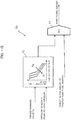
- FIG. 11C is a functional block diagram depicting a processing content of the state determination section 56A. It is noted that FIG. 11C depicts a case in which the number of hydraulic pumps is two.
- the state determination section 56A has torque computing sections 72a and 72b, an addition section 73, a pump load rate computing section 74, a pump load rate reference value setting section 75, and a comparison section 76.
- the state determination section 56A causes the torque computing section 72a to calculate the load torque of the hydraulic pump 12 from the Equation described above using the tilting amount of the hydraulic pump 12 calculated by the pump tilting amount computing section 64 and the delivery pressure of the hydraulic pump 12 detected by the pressure sensor 21. Likewise, the state determination section 56A causes the torque computing section 72b to calculate the load torque of the hydraulic pump that is not depicted. Next, the state determination section 56A causes the addition section 73 to calculate a total load torque of the two hydraulic pumps by adding up those load torques. Next, the state determination section 56A causes the pump load rate computing section 74 to calculate a pump load rate by dividing the total load torque of the two hydraulic pumps by the maximum pump torque Tmax in pump specifications of the hydraulic pump 12.
- a pump load rate that satisfies the diagnosis condition for the engine 10 is set, as a pump load rate reference value, in the pump load rate reference value setting section 75 in advance, the state determination section 56A then causes the comparison section 76 to compare the pump load rate calculated by the pump load rate computing section 74 with the pump load rate reference value thereof, determines that the two hydraulic pumps are each in the preset loaded state for acquiring the diagnosis data of the engine 10 when the pump load rate calculated by the pump load rate computing section 74 is equal to or higher than the pump load rate reference value, and outputs a valid operation flag.
- the engine diagnosis computing section 67A calculates the feature variable similarly to the first embodiment on the basis of this valid operation flag, and enables the trend data for the engine diagnosis to be displayed on the display device 38.
- the load rates of the two hydraulic pumps 12 are each equal to or higher than the preset load rate reference value during operator's normal work, it is determined that the two hydraulic pumps are each in the preset loaded state for acquiring the diagnosis data of the engine 10, and the torque correction value ⁇ Ta is validated as the diagnosis data of the engine and the feature variable is calculated only at that time.
- the pump load rate (pump load rate reference value) that satisfies the diagnosis condition for the engine 10 is, for example, 70%, and that the two hydraulic pumps are each in the preset loaded state for acquiring the diagnosis data of the engine 10 when each calculated pump load rate is equal to or higher than 70%.
- the pump tilting amount computing section 64 sequentially calculates the tilting amounts of the two hydraulic pumps while the hydraulic excavator is making a certain operation
- the torque computing sections 72a and 72b in the state determination section 56A compute the load torques of the two hydraulic pumps on the basis of the pump tilting amounts and the input delivery pressures of the two hydraulic pressures
- the addition section 73 adds up those load torques to calculate the load torque of the overall pumps.
- the pump load rate computing section 74 computes a load rate with respect to the maximum pump torque Tmax in the pump specifications
- the comparison section 76 compares the calculated load rate with that pump load rate reference value of 70%.
- This valid operation flag and the torque correction amount ⁇ Ta are input to the controlled variable computing section 57, the controlled variable computing section 57 validates the torque correction amount ⁇ Ta and captures the torque correction amount ⁇ Ta*, the filter processing section 58 performs the low-pass filter processing on this validated torque correction amount ⁇ Ta * to obtain a feature variable at a current time.
- the time history data generation section 59 calculates the magnitude of this feature variable and the change in this feature variable and adds the time history information to the feature variable, generates the time history data of the feature variable for the engine diagnosis, and stores the generated time history data in the storage device 60.
- the display computing section 61 reads the time history data of the feature variable for a predetermined period stored in the storage device 60 in response to a display request from the display device 38 and causes this time history data to be displayed as trend data for the engine diagnosis on the display device 38.
- the preset loaded state of the hydraulic pump 12 for acquiring the diagnosis data of the engine 10 is not limited to the specific operation scene of less occurrence frequency, it is possible to sufficiently ensure the operation scenes for acquiring the diagnosis data and always obtain a favorable diagnosis result.
- the load rate may be further reduced when operation scenes for acquiring the diagnosis data are secured and evaluation is to be performed.
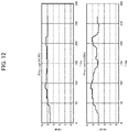
- FIGS. 12 and 13 depict examples of trend data of the feature variable when different load rate reference values are used.
- Each of FIGS. 12 and 13 depicts a case in which the load rate reference value is 70% and a case in which the load rate reference value is 50%
- FIG. 12 depicts a case in which the change in the feature variable is relatively small
- FIG. 13 depicts a case in which the feature variable gradually increases.
- the number of feature variables to be used increases in the case in which the load rate reference value is 50% from that in the case in which the load rate reference value is 70%; thus, it is possible to evaluate more detailed changes.
- a region for the evaluation is a region of a low load rate; thus, an error and the like are generated, with the result that the diagnosis and the evaluation are prone to the influence of the noise. It is, therefore, preferable to set the pump load rate reference value while taking into consideration a balance between the number of pieces of data of the feature variables to be used and the influence of the noise on the data.
- FIG. 11C depicts such a modification as well as the second embodiment.
- a load rate indicating device 77 is provided, thus operator's operating the load rate indicating device 77 makes it possible to adjust the load rate reference value in the pump load rate reference value setting section.
- FIG. 11D depicts such a modification.
- a state determination section 56B depicted in FIG. 11D additionally has a pump load rate reference value setting section 75a and a comparison section 76a, compared with the state determination section 56A depicted in FIG. 11C , a load rate reference value of 70% is set in the pump load rate reference value setting section 75, and a load rate reference value of 50% is set in the pump load rate reference value setting section 75a.
- the comparison sections 76 and 76a each compare the calculated load rate with the load rate reference value, the comparison section 76 outputs a first valid operation flag when the calculated load rate is equal to or higher than 70%, and the comparison section 76a outputs a second valid operation flag when the calculated load rate is equal to or higher than 50%.
- the controlled variable computing section 57, the filter processing section 58, the time history data generation section 59, the storage section 60, and the display computing section 61 perform processing for computing the feature variable in response to each of the first and second valid operation flags, and enable the trend data to be displayed.
- FIG. 14 is a diagram depicting an example of the trend data for the engine diagnosis displayed on the display screen 38b of the display device 38 according to such a modification.
- two types of trend data reflective of an unevenness/fluctuation tendency of the feature variables is displayed on the display screen 38b, and the two types of trend data can be simultaneously confirmed.
- the confirming person such as the operator or the maintenance person can thereby simultaneously confirm the diagnosis data based on the plurality of load rate reference values, make determination while confirming a progress per se, and grasp a stable result.
Landscapes
- Engineering & Computer Science (AREA)
- General Engineering & Computer Science (AREA)
- Mining & Mineral Resources (AREA)
- Civil Engineering (AREA)
- Structural Engineering (AREA)
- Mechanical Engineering (AREA)
- Combustion & Propulsion (AREA)
- Chemical & Material Sciences (AREA)
- Physics & Mathematics (AREA)
- Fluid Mechanics (AREA)
- General Physics & Mathematics (AREA)
- Operation Control Of Excavators (AREA)
- Control Of Vehicle Engines Or Engines For Specific Uses (AREA)
- Combined Controls Of Internal Combustion Engines (AREA)
- Control Of Positive-Displacement Pumps (AREA)
Abstract
Description
- The present invention relates to a construction machine, such as a hydraulic excavator and a crane, equipped with an engine diagnosing device.
- In a construction machine such as a hydraulic excavator and a crane, a diesel engine (hereinafter, simply referred to as "engine") is normally used as a power source of a hydraulic drive system. An abnormality in this engine leads to a reduction in output power of the engine and has a great influence such as a reduction in a performance of the construction machine and occurrence of constraints on operations; thus, it is required to detect an abnormality and ensure prevention and maintenance. In these circumstances, various engine diagnosing technologies have been conventionally proposed.
- As one of the engine diagnosing technologies, there is known, for example, a technology described in
Japanese Patent No.4853921 - According to this conventional technology, a machine body management controller collects frequency distribution information representing a relation between a signal intensity related to engine output power and an occurrence frequency whenever the machine body is actuated for a predetermined time and transmits those pieces of data to an accumulation server by a wireless communication function, and the accumulation server stores therein the data. A decrease in the output power of an engine is detected by arranging a plurality of pieces of accumulated frequency distribution information in time series and comparing the information, and the decrease in the engine output power is determined.
- According to this conventional technology, it is possible to confirm the intensity of the output power of the engine and the occurrence frequency information over a long period of time; thus, it is possible to confirm the decrease in the output power and the like over time per machine body, and to grasp a degradation situation of the engine.
- Patent Document 1:
Japanese Patent No. 4853921 - According to the engine diagnosing technology described in
Patent Document 1, the intensity corresponding to the engine output power and the frequency information are accumulated over a given period of time and the plurality of pieces of the frequency information are compared in time series; thus, it is unnecessary to prepare thresholds for determination and it is possible to determine a degree of degradation of the engine by a degree of change in a feature variable only for the machine body. However, a load actually acting on a work device depends on a content of work; thus, strictly speaking, a difference in output power is affected by a difference in a work load. In particular, even if trying to observe an aging degradation, the contents of work over a long period of time differ in a work site and the like and are expected to naturally differ in the work load. In such a case, a tendency of the engine output power is affected by the work site; therefore, it is considered that the tendency is not purely reflective of the performance of the engine and feature variable for determination includes large uncertainty (errors) although the tendency can be somewhat evaluated as a statistical tendency. - Moreover, the necessity of the long-term frequency information makes necessary a large volume of data, a memory area for computing processing, and also a cost for computing (a sophisticated controller). According to
Patent Document 1, not a machine-mounted controller but the accumulation server or the like is used via remote communication for the purpose of cost containment. However, this is a configuration adopted to constrain a cost of the machine-mounted controller, which can be said as a supportive background factor that to-be-processed data is enormous and it is difficult to cope with the data by a current machine-mounted controller at a machine-mounted controller technology level and a control technology levels to date. Moreover, it is possible for the accumulation server to handle a huge volume of data; however, a communication cost for transfer of the large volume of data from the machine body is additionally required, and a cost for achieving a diagnosis control logic is generated again in this case. - The present invention has been made in view of such situations, and an object of the present invention is to provide a construction machine in which a cost required to perform diagnosis of a degradation such as a reduction in output power of an engine is reduced while engine degradation diagnosis accuracy is improved.
- To attain the object, the present invention provides a construction machine comprising: an engine; a hydraulic system including a variable displacement hydraulic pump driven by the engine, a hydraulic actuator driven by a delivery fluid of the hydraulic pump, and a regulator that controls a displacement volume of the hydraulic pump in such a manner that an input torque of the hydraulic pump does not exceed a maximum absorption torque; a controller that computes a torque command value of speed sensing control for controlling the regulator in such a manner that the maximum absorption torque of the hydraulic pump decreases as a load torque of the hydraulic pump increases and a rotation speed of the engine decreases; and an engine diagnosing device that diagnoses the engine, wherein the engine diagnosing device includes the controller, and wherein the controller is configured to: determine whether the hydraulic pump is in a preset loaded state for acquiring diagnosis data of the engine, validate a controlled variable related to a torque command value of the speed sensing control as the diagnosis data of the engine when it is determined that the hydraulic pump is in the preset loaded state, and generate time history data using the validated controlled variable as a current feature variable, and enables the time history data to be displayed as trend data for engine diagnosis on a display device.
- In this way, since the controller determines whether the hydraulic pump is in the preset loaded state for acquiring diagnosis data of the engine, validate a controlled variable related to a torque command value of the speed sensing control as the diagnosis data of the engine when it is determined that the hydraulic pump is in the preset loaded state, and enables the time history data to be displayed as trend data for engine diagnosis on a display device, it is possible to greatly reduce a volume of data captured into the controller as the diagnosis data of the engine, and to suppress a cost required to perform the diagnosis of the degradation such as the reduction in the output power of the engine.
- Furthermore, by validating the controlled variable related to the torque command value of the speed sensing control when the hydraulic pump is in the preset loaded state as the diagnosis data of the engine, and generating the time history data for the engine diagnosis, it is possible to suppress diagnosis noise based on a measurement error or the like, accurately grasp a situation of the reduction in the output power of the engine, and improve engine degradation diagnosis accuracy.
- According to the present invention, it is possible to improve the engine degradation diagnosis accuracy while suppressing the cost required to perform diagnosis of the degradation such as the reduction in the output power of the engine.
-
-
FIG. 1 is a diagram depicting a hydraulic excavator that is a representative example of a construction machine according to the present invention. -
FIG. 2 is a diagram depicting a hydraulic system mounted in the hydraulic excavator according to a first embodiment of the present invention and a control system for the hydraulic system. -
FIG. 3 is a diagram depicting details of a regulator. -
FIG. 4 is a functional block diagram depicting a processing content of a controller. -
FIG. 5 is a functional block diagram depicting computing contents of a demanded flow rate computing section and a target tilting amount computing section. -
FIG. 6 is a diagram depicting changes in torque characteristics and a maximum torque of a hydraulic pump set by a torque control pressure from a torque control solenoid valve. -
FIG. 7A is a flowchart depicting a processing content of a state determination section. -
FIG. 7B is a functional block diagram depicting the processing content of the state determination section. -
FIG. 8 is a diagram depicting an example of trend data for engine diagnosis displayed on a display screen of a display device. -
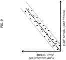
FIG. 9 is a diagram depicting that a calculated load torque of the hydraulic pump tends to have a certain error width with respect to an actual load torque of the hydraulic pump. -
FIG. 10 is a functional block diagram depicting a processing content of a controller according to a second embodiment of the present invention. -
FIG. 11A is a flowchart depicting processing contents of a pump tilting amount computing section and a state determination section. -
FIG. 11B is a functional block diagram depicting a processing content of the pump tilting amount computing section. -
FIG. 11C is a functional block diagram depicting a processing content of the state determination section. -
FIG. 11D is a diagram depicting a modification of the state determination section. -
FIG. 12 is a diagram depicting an example of trend data of feature variables when different load rate reference values are used. -
FIG. 13 is a diagram depicting an example of trend data of feature variables when different load rate reference values are used. -
FIG. 14 is a diagram depicting an example of trend data for engine diagnosis displayed on a display screen of a display device according to the modification. - Embodiments of the present invention will be described hereinafter with reference to the drawings.
-
FIG. 1 is a diagram depicting a hydraulic excavator that is a representative example of a construction machine according to the present invention. - The hydraulic excavator includes a
travel structure 101, aswing structure 102 disposed on thetravel structure 101, and a front work device attached to theswing structure 102, that is, awork device 103. - The
travel structure 101 has a pair of left andright crawlers FIG. 1 ), and thecrawlers travel motors swing structure 102 is driven by aswing motor 102a and swings on thetravel structure 101. - The
work device 103 is configured with aboom 104 attached to theswing structure 102 vertically rotatably, anarm 105 attached to theboom 104 rotatably, and abucket 106 attached to thearm 105 rotatably. Theboom 104 is driven by aboom cylinder 112, the arm is driven by anarm cylinder 113, and thebucket 106 is driven by abucket cylinder 114. Acabin 120 including an operation room is provided in a front side position on theswing structure 102. -
FIG. 2 is a diagram depicting an overall configuration including a hydraulic system and a control system for the hydraulic system mounted in the hydraulic excavator according to a first embodiment of the present invention. - The hydraulic system will first be described.
- The hydraulic system mounted in the hydraulic excavator includes: a diesel engine 10 (hereinafter, simply referred to as "engine") that is a prime mover; a variable displacement hydraulic pump 12 driven by the engine 10; a control valve 16 incorporating therein a plurality of control spools controlling flows of hydraulic fluids supplied to a plurality of actuators 14 (only one of which is depicted in
FIG. 2 for the sake of convenience); a main relief valve 18 that is connected to a hydraulic line of a hydraulic pump 12 and that regulates an upper limit of a pressure applied to the control valve 16 (delivery pressure of the hydraulic pump 12); a plurality of hydraulic pilot type operation devices 20 (only one of which is depicted inFIG. 2 for the sake of convenience) generating command pilot pressures (operation signals) to switch over the plurality of control spools incorporated in the control valve 16; a shuttle valve block 22 incorporating therein a plurality of shuttle valves that select a highest command pilot pressure among the command pilot pressures introduced from the plurality of operation devices 20 to the control valve 16 and that generate a pump flow rate control pressure; and a regulator 24 that controls a tilting amount (displacement volume, that is, capacity) of the hydraulic pump 12 and controls the delivery flow rate of the hydraulic pump 12. - Each of the plurality of
operation devices 20 has anoperation lever 20a and generates the command pilot pressure by operator's operating theoperation lever 20a, and the intended hydraulic actuator is driven by guiding this command pilot pressure to thecontrol valve 16. - The hydraulic excavator depicted in
FIG. 1 operates under a mechanism such that the hydraulic fluid delivered from thehydraulic pump 12 is supplied to eachhydraulic actuator 14 via thecontrol valve 16 in this way. - The
regulator 24 has apump actuator 26 that drives a displacement volume change member (for example, a swash plate) of thehydraulic pump 12, and a pumpflow control valve 28 and a pumptorque control valve 30 that control a hydraulic pressure introduced to thepump actuator 26 and that control a tilting amount of thehydraulic pump 12. - The control system will next be described.
- The control system includes: a rotary dial type target rotation speed indicating device 32 that generates an indication signal of a target rotation speed of the engine 10 by operator's operating rotation; an engine rotation sensor 33 that detects a rotation speed (an actual rotation speed) of the engine 10; a pressure sensor 21 that detects a delivery pressure of the hydraulic pump 12; a plurality of pressure sensors 35 as operation sensors (only one of which is depicted in
FIG. 2 for the sake of convenience) that detect command pilot pressures (operation signals) generated by the plurality of operation devices 20; a pressure sensor 36 that detects a pump flow control pressure generated by the shuttle valve block 22; a controller 37 to which the indication signal from the target rotation speed indicating device 32 and detection signals from the engine rotation sensor 33 and the pressure sensors 21, 35, and 36 are input, and which performs predetermined computing processing; a display device 38 to which a display signal from the controller 37 is input and which displays time history data (to be described later) of a feature variable; and a flow control solenoid valve 39 and a torque control solenoid valve 40 to which a command signal from the controller 37 is input and which output a flow control pressure and a torque control pressure to the pump flow control valve 28 and the pump torque control valve 30 of the regulator 24, respectively. -
FIG. 3 is a diagram depicting details of theregulator 24. - The
regulator 24 has thepump actuator 26 that drives the displacement volume change member of thehydraulic pump 12, and the pumpflow control valve 28 and the pumptorque control valve 30 that control a driving pressure introduced to thepump actuator 26 and that control the tilting amount of the hydraulic pump. - The
pump actuator 26 is a servo piston including anactuating piston 26a having a large-diameterpressure receiving section 26b and a small-diameterpressure receiving section 26c, a control pressure adjusted by the pumpflow control valve 28 and the pumptorque control valve 30 to a pressure in a range of a constant pilot pressure of a pilot pump Pp from a tank pressure is introduced to the large-diameterpressure receiving section 26b, and the constant pilot pressure of the pilot pump Pp is introduced to the small-diameterpressure receiving section 26c. When the same constant pilot pressure of the pilot pump Pp is introduced to both of thepressure receiving sections actuating piston 26a moves in a left direction inFIG. 3 , a tilting amount of the swash plate of thehydraulic pump 12 is reduced, and a pump delivery flow rate is reduced. When the pressure introduced to the large-diameterpressure receiving section 26b decreases, then theactuating piston 26a moves in a right direction inFIG. 3 , the tilting amount of the swash plate of thehydraulic pump 12 is increased, and the pump delivery flow rate is increased. - The pump
flow control valve 28 has apressure receiving section 28a to which the flow control pressure output from the flowcontrol solenoid valve 39 is introduced. - When the flow control pressure output from the flow
control solenoid valve 39 is lower, then a spool in the pumpflow control valve 28 moves in the left direction inFIG. 3 , the constant pilot pressure from the pilot pump Pp is introduced to the large-diameterpressure receiving section 26b through the pumpflow control valve 28 and the pumptorque control valve 39, the tilting amount of thehydraulic pump 12 is reduced, and the pump delivery flow rate is reduced. - When the pump flow control pressure output from the flow
control solenoid valve 39 is higher, then the spool in the pumpflow control valve 28 moves in the right direction inFIG. 3 , and the large-diameterpressure receiving section 26b is introduced to a drain (tank) through the pumptorque control valve 30 and the pumpflow control valve 28, so that the tilting amount of thehydraulic pump 12 is increased, and the pump delivery flow rate is increased. - In this way, the pump
flow control valve 28 controls the pump delivery flow rate in such a manner that the pump delivery flow rate is equal to a pump flow rate in response to the pump flow control pressure. - The pump
torque control valve 30 has apressure receiving section 30a to which a delivery pressure of thehydraulic pump 12 is introduced and apressure receiving section 30b to which the torque control pressure output from the torquecontrol solenoid valve 40, and aspring 30c is located opposite to thepressure receiving sections - When a hydraulic force by the delivery pressure of the
hydraulic pump 12 introduced to thepressure receiving section 30a is lower than a difference value between an urging force of thespring 30c and a hydraulic force by the torque control pressure of the torquecontrol solenoid valve 40 introduced to thepressure receiving section 30b, then a spool in the pumptorque control valve 30 moves in the right direction inFIG. 3 , the large-diameterpressure receiving section 26b is made in communication with the pumpflow control valve 28, and the pump delivery flow rate is determined by the pumpflow control valve 28. - When the hydraulic force by the delivery pressure of the
hydraulic pump 12 introduced to thepressure receiving section 30a is higher than the difference value between the urging force of thespring 30c and the hydraulic force by the torque control pressure of the torquecontrol solenoid valve 40 introduced to thepressure receiving section 30b, then the spool in the pumptorque control valve 30 moves in the left direction inFIG. 3 , the constant pilot pressure from the pilot pump Pp is introduced to the large-diameterpressure receiving section 26b through the pumptorque control valve 30, the tilting amount of thehydraulic pump 12 is smaller, and the pump delivery flow rate is reduced. - In this way, the delivery flow rate of the
hydraulic pump 12 is reduced in response to a rise of the delivery pressure of thehydraulic pump 12, thereby exercising control in such a manner that an absorption torque of thehydraulic pump 12 does not exceed a maximum torque determined by the difference value between the urging force of thespring 30c and the hydraulic force by the torque control pressure from the torquecontrol solenoid valve 40 introduced to thepressure receiving section 30b. - Furthermore, the maximum torque is variable by the torque control pressure from the torque
control solenoid valve 40. This respect will be described later. -
FIG. 4 is a functional block diagram depicting a processing content of thecontroller 37. - The
controller 37 is configured to determine whether thehydraulic pump 12 is in a preset loaded state for acquiring diagnosis data of theengine 10, validate a controlled variable related to a torque command value of speed sensing control as the diagnosis data of theengine 10 when it is determined that thehydraulic pump 12 is in the preset loaded state, generate time history data using this validated controlled variable as a current feature variable, and enable this time history data to be displayed as trend data for engine diagnosis on thedisplay device 38. - Details of the processing content will be described hereinafter.
- The
controller 37 has a flowcontrol computing section 65 of positive pump control and a torquecontrol computing section 66 for speed sensing control. - The flow
control computing section 65 has a demanded flowrate computing section 45 that calculates a demanded flow rate on the basis of the pump flow control pressure (highest command pilot pressure) detected by thepressure sensor 36, a target tiltingamount computing section 46 that calculates a target tilting amount of thehydraulic pump 12 from the calculated demanded flow rate, and acurrent conversion section 47 that converts the calculated target tilting amount into a command current for the flowcontrol solenoid valve 39 and that outputs the command current. -
FIG. 5 is a functional block diagram depicting computing contents of the demanded flowrate computing section 45 and the target tiltingamount computing section 46. The demanded flowrate computing section 45 includes a table of the pump flow control pressure and the demanded flow rate set such that the demanded flow rate increases as the pump flow control pressure increase, and the demanded flowrate computing section 45 calculates a corresponding demanded flow rate by referring the pump flow control pressure detected by thepressure sensor 36 to the table. The target tiltingamount computing section 46 includes a table of the demanded flow rate and the target tilting amount set such that the target tilting amount increases as the demanded flow rate increases, and the target tiltingamount computing section 46 calculates a corresponding target tilting amount by referring the calculated demanded flow rate to the table. - The
current conversion section 47 is configured to generate a command current that is made higher as the target tilting amount is larger, the flowcontrol solenoid valve 39 is excited by the command current and outputs the flow control pressure to thepressure receiving section 28a in the pumpflow control valve 28, and the delivery flow rate of thehydraulic pump 12 is thereby controlled as previously described. Thehydraulic pump 12 can thereby control the delivery flow rate of thehydraulic pump 12 by a scheme referred to as positive pump control to increase the delivery flow rate of thehydraulic pump 12 in response to an operation amount (demanded flow rate) of theoperation lever 20a of theoperation device 20. - With reference back to
FIG. 4 , the torquecontrol computing section 66 for speed sensing control has: adeviation computing section 51 that performs computing of (actual rotation speed) - (target rotation speed) = (rotation speed deviation) on the basis of the target rotation speed of theengine 10 indicated by the target rotationspeed indicating device 32 and the actual rotation speed of theengine 10 detected by theengine rotation sensor 33, and that calculates a rotation speed deviation ΔN; a correctionamount computing section 52 that calculates a torque correction amount ΔTa from the calculated rotation speed deviation ΔN; a referencetorque computing section 53 that calculates a reference torque T0 of thehydraulic pump 12 determined from an excavator operation, an excavator mode, and the like; anaddition section 54 that corrects the reference torque T0 by adding the torque correction amount ΔTa to this reference torque T0 and that calculates a new torque command value Ta of thehydraulic pump 12; and acurrent conversion section 55 that converts the calculated torque command value Ta into a command current for the torquecontrol solenoid valve 40 and that outputs the command current to the torquecontrol solenoid valve 40. Thecurrent conversion section 55 is configured to output the command current that is made higher as the torque command value Ta is lower than the reference torque T0, and the torquecontrol solenoid valve 40 is excited by the command current and outputs the torque control pressure to thepressure receiving section 30b in the pumptorque control valve 30, and the maximum absorption torque of thehydraulic pump 12 is thereby controlled as described previously. -
FIG. 6 is a diagram depicting changes in torque characteristics and the maximum torque of thehydraulic pump 12 set by the torque control pressure from the torquecontrol solenoid valve 40. When the torque correction amount ΔTa computed by the correctionamount computing section 52 is zero, theaddition section 54 calculates the torque command value Ta equal to the reference torque T0 calculated by the referencetorque computing section 53, and the torque control pressure output from the torquecontrol solenoid valve 40 to thepressure receiving section 30b in the pumptorque control valve 30 takes on a predetermined value, torque characteristics and the maximum torque of thehydraulic pump 12 set by theregulator 24 are Sa and Tmaxa, respectively. When the absorption torque (load torque) of thehydraulic pump 12 increases and the actual rotation speed of theengine 10 decreases, then the torque correction amount ΔTa takes on a negative value and the torque command value Ta calculated by theaddition section 54 decreases. At this time, the torque control pressure output from the torquecontrol solenoid valve 40 to thepressure receiving section 30b in the pumptorque control valve 30 rises depending on the decrease in the torque command value Ta, and the torque characteristics and the maximum torque of thehydraulic pump 12 set by theregulator 24 are reduced to Sb and Tmaxb, and then to Sc and Tmaxc from Sa and Tmaxa, respectively as indicated by an arrow ofFIG. 6 as the torque control pressure rises. - When the
hydraulic pump 12 is driven using theengine 10 as in the hydraulic excavator, if the load on thehydraulic pump 12 exceeds the engine torque, it is impossible to drive thehydraulic pump 12, resulting in an engine stop. To prevent this engine stop, the torquecontrol computing section 66 for the speed sensing control over theengine 10 is provided. - According to this speed sensing control, even in a case of a reduction in engine output power (torque) or the like for some factor, the output power (absorption torque) of the
hydraulic pump 12 is adjusted; thus, the engine output power and the pump absorption torque are controlled in a balanced state. Therefore, grasping this pump control state makes it possible to indirectly grasp a drive state of theengine 10. - The
controller 37 further has an enginediagnosis computing section 67 that serves as an engine diagnosing device that diagnoses theengine 10. The enginediagnosis computing section 67 diagnoses theengine 10 by grasping the pump control state by the speed sensing control on the basis of the concept described above. - In the
FIG. 4 , the engine diagnosis computing section 67 has: a state determination section 56 that determines whether the hydraulic pump 12 is in the preset loaded state for acquiring the diagnosis data of the engine 10; a controlled variable computing section 57 that validates and captures the torque correction amount ΔTa that is the controlled variable related to the torque command value Ta of the speed sensing control as the diagnosis data of the engine 10 when the determination result by the state determination section 56 is satisfied (is true) and when it is determined that the hydraulic pump 12 is in the preset loaded state; a filter processing section 58 that performs low-pass filter processing on this validated torque correction amount ΔTa* (validated controlled variable) for stabilization; a time history data generation section 59 that uses the validated torque correction amount ΔTa* (validated controlled variable) by way of the filter processing section 58 as a current feature variable, that calculates a magnitude of this feature variable and a change in this feature variable and adds time history information to this feature variable, and that generates the time history data of the feature variable for the engine diagnosis; a storage device 60 that stores the generated time history data of the feature variable; and a display computing section 61 that reads the time history data of the feature variable for a predetermined period stored in the storage section 60 in response to a display request from the display device 38 and that causes this time history data to be displayed as trend data for the engine diagnosis on the display device 38. - The
display device 38 has anoperation section 38a and adisplay screen 38b, outputs a display request signal to thecontroller 37 by operating theoperation section 38a, and displays the time history data of the feature variable for the predetermined period acquired from thestorage device 60 via thedisplay computing section 61 in thecontroller 37 as the trend data for the engine diagnosis on thedisplay screen 38b. - While the engine
diagnosis computing section 67 sets the controlled variable to be validated as the diagnosis data of the engine by the controlledvariable computing section 57 as the torque correction amount ΔTa, the controlled variable may be other than ΔTa as long as the controlled variable is related to the torque command value Ta of the speed sensing control. For example, when the correctionamount computing section 52 is a proportional element computing section, a similar effect can be obtained even using a rotation speed deviation ΔN input from the previous stage and different by a proportional coefficient multiple as the controlled variable. Alternatively, the torque command value Ta of the speed sensing control may be used as the controlled variable per se. - Furthermore, the
display device 38 is not limited to the display device provided in the hydraulic excavator but may be a display device provided outside of the hydraulic excavator such as that provided in an administrative room. In that case, information may be exchanged via wireless communication means. - Details of determination processing of the
state determination section 56 will next be described. - In the present embodiment, the
state determination section 56 validates the torque correction value ΔTa as the engine diagnosis data while limiting the preset loaded state of thehydraulic pump 12 for acquiring the diagnosis data of theengine 10 to a specific operation scene of the hydraulic system that satisfies a diagnosis condition for theengine 10. The specific operation scene of the hydraulic system that satisfies the diagnosis condition for theengine 10 means herein an operation scene where the load torque (absorption torque) of thehydraulic pump 12 is in a stable state. - Specifically, at a time of warming-up or the like of the
engine 10 or a hydraulic operating fluid, from a view point of easiness and security assurance of the work, it often occurs that theboom 104 is raised to set theboom cylinder 112 into a stroke end state, theoperation lever 20a of theboom operation device 20 is fully operated, the delivery pressure of thehydraulic pump 12 is raised up to a set pressure of themain relief valve 18, and themain relief valve 18 is set into a relief state. In this operation scene, the delivery flow rate and the delivery pressure of thehydraulic pump 12 are kept at certain values; thus, it is possible to easily estimate the loaded state of thehydraulic pump 12. Thestate determination section 56 estimates such a loaded state of the hydraulic pump 12 (loaded state in which the delivery pressure of thehydraulic pump 12 is constant to be equal to the relief pressure of themain relief valve 18, and in which the tilting amount of thehydraulic pump 12 is constant) as the specific operation scene that satisfies the diagnosis condition for theengine 10, and validates the torque correction amount ΔTa to the torque correction amount ΔTa* while limiting the preset loaded state of thehydraulic pump 12 to such an operation scene. -
FIG. 7A is a flowchart depicting a processing content of thestate determination section 56. - The
state determination section 56 determines whether theoperation device 20 is fully operated in a boom raising direction and themain relief valve 18 is in the relief state on the basis of the operation signal for boom raising of theoperation device 20 detected by the pressure sensor 35 (operation sensor) and the delivery pressure of thehydraulic pump 12 detected by the pressure sensor 21 (Steps S100 and S110), and determines that the hydraulic system is in the specific operation scene and thehydraulic pump 12 is in the preset loaded state when theoperation device 20 is fully operated in the boom raising direction and themain relief valve 18 is in the relief state, and then outputs a valid operation flag (Step S120). -
FIG. 7B is a functional block diagram depicting the processing content of thestate determination section 56. - The
state determination section 56 causes acomparison section 61b to compare the operation signal (command pilot pressure) indicating boom raising of theoperation device 20 detected by the pressure sensor 35 (operation sensor) with an operation signal (command pilot pressure) indicating a boom fully raising operation and preset to asetting section 61a, and determines whether the operation signal indicating the boom raising is equal to or greater than the operation signal indicating the boom fully raising operation. Furthermore, thestate determination section 56 causes acomparison section 62b to compare the delivery pressure of thehydraulic pump 12 detected by thepressure sensor 21 with the set pressure of themain relief valve 18 preset to asetting section 62a, and determines whether the delivery pressure of thehydraulic pump 12 is equal to or higher than the set pressure of themain relief valve 18. When the operation signal indicating the boom raising is equal to or greater than the operation signal indicating the boom fully raising operation and the delivery pressure of thehydraulic pump 12 is equal to or higher than the set pressure of the main relief valve 18 (when AND conditions are satisfied), thestate determination section 56 determines that the hydraulic system is in the specific operation scene described above, and outputs the valid operation flag (Step S120). This valid operation flag serves as a flag it is determined that thehydraulic pump 12 is in the preset loaded state for acquiring the diagnosis data of theengine 10. - It is noted that in the embodiment described above, the specific operation scene is determined by detecting that the
operation lever 20a is fully operated. However, if the tilting amount of thehydraulic pump 12 can be directly grasped, the tilting amount may be directly calculated and evaluated as an alternative to detecting that theoperation lever 20a is fully operated. In this case, it is not necessary for the tilting amount to be a maximum value but it suffices to be capable of detecting that the tilting amount is controlled to be a certain fixed value (in a stable state). More specifically, it suffices to grasp that the load torque of the hydraulic pump is in a stable state. Because of (load torque) = (pressure) × (tilting amount), obtaining a state in which the tilting amount is equal to the fixed value and a state in which the delivery pressure is fixed (maximum) makes it possible to evaluate that the load torque of thehydraulic pump 12 is in the stable state and that thehydraulic pump 12 is in the preset loaded state. - Operations in the present embodiment will next be described.
- While the hydraulic excavator is operating and conducting work, the
controller 37 performs the following computing. A case in which the specific operation scene satisfying the diagnosis condition for theengine 10 is the scene where the operation lever is fully operated for the boom raising and the delivery pressure of thehydraulic pump 12 is equal to the relief pressure, will be described herein. - The
state determination section 56 acquires the operation signal (command pilot pressure) indicating the boom raising from the detection signal of thepressure sensor 35, causes thecomparison section 61b to compare the acquired operation signal indicating the boom raising with the preset operation signal indicating the boom fully raising operation, and determines whether the operation signal indicating the boom raising is equal to or greater than the operation signal indicating the boom fully raising operation. Furthermore, thestate determination section 56 acquires the delivery pressure of thehydraulic pump 12 from the detection signal of thepressure sensor 21, causes thecomparison section 62b to compare the acquired delivery pressure with the set pressure of themain relief valve 18, and determines whether the delivery pressure of thehydraulic pump 12 is equal to or higher than the set pressure of themain relief valve 18. When the AND conditions are satisfied in these twocomparison sections state determination section 56 determines that thehydraulic pump 12 is in the preset loaded state for acquiring the diagnosis data of theengine 10, and the valid operation flag indicates a true value. - This valid operation flag and the torque correction amount ΔTa are input to the controlled
variable computing section 57, and the controlledvariable computing section 57 validates the torque correction amount ΔTa and captures the torque correction amount ΔTa*. Thefilter processing section 58 performs the low-pass filter processing on this validated torque correction amount ΔTa* over a valid section to obtain a stabilized quantity of state. This quantity of state is the feature variable at a current time. The time historydata generation section 59 calculates the magnitude of this feature variable and the change in this feature variable and adds the time history information to the feature variable, generates the time history data of the feature variable for the engine diagnosis, and stores the generated time history data in thestorage device 60. While the time history data of the feature variable referred herein is calculated in sequence online, it is possible to reduce a memory area used by thestorage device 60 by reducing the time history data to the number of times of sampling necessary for display as the time history data. For example, since even data acquired one piece per hour, one piece per day, or the like can often sufficiently express a tendency of a failure or a degradation to grasp the failure or the degradation, it is possible to minimize information to be handled by decimating the time history data to sampling data sufficient to express the tendency. - As a result, in a case of actuating the hydraulic system in such a manner that the specific load on the hydraulic pump acts on the hydraulic system, it is possible to calculate the torque correction amount ΔTa on the basis of the deviation ΔN between the engine target rotation speed and the actual rotation speed, calculate the feature variable in such a manner that the torque correction amount ΔTa is further subjected to the filter processing to suppress a dynamic influence, and stably calculate the feature variable. By creating the time history data for the engine diagnosis using this feature variable and storing the time history data in the
storage device 60, it is possible to display the magnitude of the time history data and the tendency of the change in the time history data on thedisplay device 38 as the trend data for the engine diagnosis. -
FIG. 8 is a diagram depicting an example of the trend data for the engine diagnosis displayed on thedisplay screen 38b of thedisplay device 38. By operating thedisplay device 38 to display the trend data on the display screen as depicted inFIG. 8 and viewing a temporal change, a confirming person such as the operator or a maintenance person can determine a degree of the degradation of theengine 10. - In this way, according to the present embodiment, the
controller 37 determines whether thehydraulic pump 12 is in the preset loaded state, and validates the controlled variable (for example, the torque correction value ΔTa) related to the torque command value Ta of the speed sending control as the diagnosis data of theengine 10 and enables the controlled variable to be displayed as the trend data for the engine diagnosis when it is determined that thehydraulic pump 12 is in the preset loaded state; thus, it is thereby possible to greatly reduce the volume of data captured in thecontroller 37 as the diagnosis data of theengine 10 and suppress a cost required to perform diagnosis of the degradation such as the reduction in the output power of theengine 10. - Furthermore, the time history data for the engine diagnosis is generated as the diagnosis data of the
engine 10 by validating the controlled variable related to the torque command value Ta of the speed sensing control when thehydraulic pump 12 is in the preset loaded state (operation scene where the load torque of thehydraulic pump 12 is in the stable state), it is possible to suppress diagnosis noise based on a measurement error or the like, accurately grasp a situation of the reduction in the output power of theengine 10, and improve accuracy of the diagnosis of the engine degradation as depicted inFIG. 8 . - While a case in which the number of hydraulic pumps is one has been described in the above embodiment, it is also possible to calculate loaded states of a plurality of hydraulic pumps by similarly calculating a load on each hydraulic pump and summing up the loads. Furthermore, as for the torque correction amount ΔTa, it is possible to grasp the state of the engine by calculating the torque correction amount ΔTa of one of the hydraulic pumps since the plurality of hydraulic pumps are driven by the same engine.
- A second embodiment of the present invention will be described.
- In the first embodiment, the
state determination section 56 limits the "preset loaded state" of thehydraulic pump 12 for acquiring the diagnosis data of theengine 10 to the specific operation scene of the hydraulic system that satisfies the diagnosis condition for theengine 10; thus, it is possible to accurately grasp the loaded state of thehydraulic pump 12. Owing to this, it is possible to suppress the diagnosis noise and accurately grasp the situation of the reduction in the output power of theengine 10. - On the other hand, however, since the "preset loaded state" of the
hydraulic pump 12 for acquiring the diagnosis data of theengine 10 is limited to the specific operation scene, it is estimated that an occurrence frequency of such a limited operation scene is low depending on an environment such as a manner of operator's operation and a content of work, a constraint on a site, and the like, the operation scene for acquiring the diagnosis data is rare depending on situations, and it is impossible to provide good-quality diagnosis. - The second embodiment is intended to improve the respects and to be capable of sufficiently acquiring the diagnosis data of the
engine 10. Details of the second embodiment will be described hereinafter. The same parts as those in the first embodiment are denoted by the same reference characters and description thereof is omitted. - A concept of the present embodiment will first be described.
- The tilting amount of the
hydraulic pump 12 can be calculated within thecontroller 37 since the tilting amount of thehydraulic pump 12 is controlled by thecontroller 37. Furthermore, the delivery pressure of thehydraulic pump 12 is detected by thepressure sensor 21 and available within thecontroller 37. It is, therefore, possible to calculate the loaded state of thehydraulic pump 12 using the pump tilting amount and the pump delivery pressure. - A load torque T acting on the
hydraulic pump 12 is expressed by the following Equation.

- q: Tilting amount of hydraulic pump 12 (cc/rev)
- P: Delivery pressure of
hydraulic pump 12 - When a plurality of
hydraulic pumps 12 are used, it is possible to calculate a torque of the overall pumps by calculating the tilting amount q and the delivery pressure P of each of thehydraulic pumps 12 to obtain the load torque T and by summing up the load torques T. - In the hydraulic system including such a
hydraulic pump 12, taking the measurement error, the noise, and the like of the pressure sensor 25 into consideration, situations of errors in the calculated torque are those depicted inFIG. 9 . Since error factors include an error in detection of the delivery pressure of thehydraulic pump 12 and an error in calculation of the tilting amount of thehydraulic pump 12, the calculated load torque of thehydraulic pump 12 tends to have a certain error width with respect to the actual load torque of thehydraulic pump 12. It is, therefore, effective to perform diagnosis and evaluation in a region of a high pump load torque that makes it possible to apparently reduce such error factors. -
FIG. 10 is a functional block diagram depicting a processing content of acontroller 37A according to the second embodiment of the present invention. - In the
controller 37A, the flowcontrol computing section 65 and the torquecontrol computing section 66 for the speed sensing control are the same as those in the first embodiment. On the other hand, an engine diagnosis computing section (engine diagnosing device) 67A differs from the enginediagnosis computing section 67 according to the first embodiment in that the enginediagnosis computing section 67A further includes a pump tiltingamount computing section 64 and the target tilting amount calculated by the target tiltingamount computing section 46 is input to astate determination section 56A as an alternative to the detection signal (boom raising command) of thepressure sensor 35. -
FIG. 11A is a flowchart depicting processing contents of the pump tiltingamount computing section 64 and thestate determination section 56A. - The
controller 37A causes the pump tiltingamount computing section 64 to calculate a current tilting amount of thehydraulic pump 12 on the basis of the torque command value Ta calculated by the torquecontrol computing section 66 for the speed sensing control, the delivery pressure of thehydraulic pump 12 detected by thepressure sensor 21, and the target tilting amount calculated by the flowcontrol computing section 65 for the positive pump control (Step S200). Next, thecontroller 37A causes thestate determination section 56A to calculate the load torque of thehydraulic pump 12 using the pump tilting amount calculated by the pump tiltingamount computing section 64 and the delivery pressure of thehydraulic pump 12 detected by the pressure sensor 21 (Step S210), to further calculate a pump load rate by dividing the load torque by a maximum pump torque Tmax of the hydraulic pump 12 (S220), to determine whether this pump load rate is equal to or higher than a preset pump load rate (S230), and to determine that thehydraulic pump 12 is in the preset loaded state when the pump load rate is equal to or higher than a preset pump load rate and to output the effective operation flag (S240). -
FIG. 11B is a functional block diagram depicting the processing content of the pump tiltingamount computing section 64. The pump tiltingamount computing section 64 has a limited tiltingamount computing section 70 and a minimumvalue selection section 71. - The torque characteristics of the
hydraulic pump 12 depicted inFIG. 6 are set in the limited tiltingamount computing section 70, and the pump tiltingamount computing section 64 causes the limited tiltingamount computing section 70 to calculate a limited pump tilting amount for the speed sensing control on the basis of the torque command value Ta calculated by the torquecontrol computing section 66 for the speed sensing control and the delivery pressure of thehydraulic pump 12 detected by thepressure sensor 21. In other words, the limited tiltingamount computing section 70 updates the torque characteristics of thehydraulic pump 12 in such a manner that the maximum torque is made lower as the torque command value Ta is smaller, refers to the delivery pressure of thehydraulic pump 12 corresponding to the updated torque characteristics, and calculates the limited pump tilting amount for the speed sensing control at that time. - Next, the pump tilting
amount computing section 64 causes the minimumvalue selection section 71 to select, as a current tilting amount of thehydraulic pump 12, a smaller tilting amount out of the limited pump tilting amount calculated by the limited pump tiltingamount computing section 70 and the target tilting amount calculated by the flowcontrol computing section 65 of the positive pump control. - In this way, the pump tilting
amount computing section 64 estimates the current tilting amount of thehydraulic pump 12 by performing computing processing simulating operations of theregulator 24. - It is noted that when the
hydraulic pump 12 includes a position sensor that detects the tilting amount, a measurement value by the position sensor may be used as an alternative to a calculated value by the pump tiltingamount computing section 64. -
FIG. 11C is a functional block diagram depicting a processing content of thestate determination section 56A. It is noted thatFIG. 11C depicts a case in which the number of hydraulic pumps is two. Thestate determination section 56A hastorque computing sections addition section 73, a pump loadrate computing section 74, a pump load rate referencevalue setting section 75, and acomparison section 76. - The
state determination section 56A causes thetorque computing section 72a to calculate the load torque of thehydraulic pump 12 from the Equation described above using the tilting amount of thehydraulic pump 12 calculated by the pump tiltingamount computing section 64 and the delivery pressure of thehydraulic pump 12 detected by thepressure sensor 21. Likewise, thestate determination section 56A causes thetorque computing section 72b to calculate the load torque of the hydraulic pump that is not depicted. Next, thestate determination section 56A causes theaddition section 73 to calculate a total load torque of the two hydraulic pumps by adding up those load torques. Next, thestate determination section 56A causes the pump loadrate computing section 74 to calculate a pump load rate by dividing the total load torque of the two hydraulic pumps by the maximum pump torque Tmax in pump specifications of thehydraulic pump 12. A pump load rate that satisfies the diagnosis condition for theengine 10 is set, as a pump load rate reference value, in the pump load rate referencevalue setting section 75 in advance, thestate determination section 56A then causes thecomparison section 76 to compare the pump load rate calculated by the pump loadrate computing section 74 with the pump load rate reference value thereof, determines that the two hydraulic pumps are each in the preset loaded state for acquiring the diagnosis data of theengine 10 when the pump load rate calculated by the pump loadrate computing section 74 is equal to or higher than the pump load rate reference value, and outputs a valid operation flag. - The engine
diagnosis computing section 67A calculates the feature variable similarly to the first embodiment on the basis of this valid operation flag, and enables the trend data for the engine diagnosis to be displayed on thedisplay device 38. - Operations in the second embodiment will next be described.
- In the second embodiment, when the load rates of the two
hydraulic pumps 12 are each equal to or higher than the preset load rate reference value during operator's normal work, it is determined that the two hydraulic pumps are each in the preset loaded state for acquiring the diagnosis data of theengine 10, and the torque correction value ΔTa is validated as the diagnosis data of the engine and the feature variable is calculated only at that time. It is assumed herein that the pump load rate (pump load rate reference value) that satisfies the diagnosis condition for theengine 10 is, for example, 70%, and that the two hydraulic pumps are each in the preset loaded state for acquiring the diagnosis data of theengine 10 when each calculated pump load rate is equal to or higher than 70%. - The pump tilting
amount computing section 64 sequentially calculates the tilting amounts of the two hydraulic pumps while the hydraulic excavator is making a certain operation, thetorque computing sections state determination section 56A compute the load torques of the two hydraulic pumps on the basis of the pump tilting amounts and the input delivery pressures of the two hydraulic pressures, and theaddition section 73 adds up those load torques to calculate the load torque of the overall pumps. Furthermore, the pump loadrate computing section 74 computes a load rate with respect to the maximum pump torque Tmax in the pump specifications, and thecomparison section 76 compares the calculated load rate with that pump load rate reference value of 70%. When the calculated load rate is equal to or lower than 70%, then the condition is not satisfied, a new feature variable is not calculated, and a previous value is held. When the load rate is equal to or higher than 70%, then the valid operation flag indicates a true value, and the following computing is performed similarly to the first embodiment. - This valid operation flag and the torque correction amount ΔTa are input to the controlled
variable computing section 57, the controlledvariable computing section 57 validates the torque correction amount ΔTa and captures the torque correction amount ΔTa*, thefilter processing section 58 performs the low-pass filter processing on this validated torque correction amount ΔTa* to obtain a feature variable at a current time. The time historydata generation section 59 calculates the magnitude of this feature variable and the change in this feature variable and adds the time history information to the feature variable, generates the time history data of the feature variable for the engine diagnosis, and stores the generated time history data in thestorage device 60. Thedisplay computing section 61 reads the time history data of the feature variable for a predetermined period stored in thestorage device 60 in response to a display request from thedisplay device 38 and causes this time history data to be displayed as trend data for the engine diagnosis on thedisplay device 38. - It is thereby possible to improve accuracy of the diagnosis of the engine degradation while suppressing a cost required to perform diagnosis of the degradation such as the reduction in the output power of the
engine 10, similarly to the first embodiment. - Furthermore, in the present embodiment, since the preset loaded state of the
hydraulic pump 12 for acquiring the diagnosis data of theengine 10 is not limited to the specific operation scene of less occurrence frequency, it is possible to sufficiently ensure the operation scenes for acquiring the diagnosis data and always obtain a favorable diagnosis result. - While the pump load rate reference value is set to 70% in the second embodiment, the load rate may be further reduced when operation scenes for acquiring the diagnosis data are secured and evaluation is to be performed.
-
FIGS. 12 and13 depict examples of trend data of the feature variable when different load rate reference values are used. Each ofFIGS. 12 and13 depicts a case in which the load rate reference value is 70% and a case in which the load rate reference value is 50%,FIG. 12 depicts a case in which the change in the feature variable is relatively small, andFIG. 13 depicts a case in which the feature variable gradually increases. - As clear from comparison of the case in which the load rate reference value is 70% with the case in which the load rate reference value is 50% in each of
FIGS. 12 and13 , the number of feature variables to be used increases in the case in which the load rate reference value is 50% from that in the case in which the load rate reference value is 70%; thus, it is possible to evaluate more detailed changes. However, as previously described, a region for the evaluation is a region of a low load rate; thus, an error and the like are generated, with the result that the diagnosis and the evaluation are prone to the influence of the noise. It is, therefore, preferable to set the pump load rate reference value while taking into consideration a balance between the number of pieces of data of the feature variables to be used and the influence of the noise on the data. - For this reason, it is desirable to be capable of setting the load rate reference value depending on situations by making it possible to optionally change the load rate reference value from outside.
-
FIG. 11C depicts such a modification as well as the second embodiment. In other words, as indicated by a chain line inFIG. 11B , a loadrate indicating device 77 is provided, thus operator's operating the loadrate indicating device 77 makes it possible to adjust the load rate reference value in the pump load rate reference value setting section. - Moreover, there are cases in which adjusting the load rate reference value by the operator is assumed to be cumbersome; thus, a plurality of load rate reference values may be set and the trend data may be displayed by computing feature variables for the plurality of load rate reference values.
-
FIG. 11D depicts such a modification. Astate determination section 56B depicted inFIG. 11D additionally has a pump load rate referencevalue setting section 75a and acomparison section 76a, compared with thestate determination section 56A depicted inFIG. 11C , a load rate reference value of 70% is set in the pump load rate referencevalue setting section 75, and a load rate reference value of 50% is set in the pump load rate referencevalue setting section 75a. Thecomparison sections comparison section 76 outputs a first valid operation flag when the calculated load rate is equal to or higher than 70%, and thecomparison section 76a outputs a second valid operation flag when the calculated load rate is equal to or higher than 50%. - The controlled
variable computing section 57, thefilter processing section 58, the time historydata generation section 59, thestorage section 60, and thedisplay computing section 61 perform processing for computing the feature variable in response to each of the first and second valid operation flags, and enable the trend data to be displayed. -
FIG. 14 is a diagram depicting an example of the trend data for the engine diagnosis displayed on thedisplay screen 38b of thedisplay device 38 according to such a modification. As depicted inFIG. 14 , two types of trend data reflective of an unevenness/fluctuation tendency of the feature variables is displayed on thedisplay screen 38b, and the two types of trend data can be simultaneously confirmed. The confirming person such as the operator or the maintenance person can thereby simultaneously confirm the diagnosis data based on the plurality of load rate reference values, make determination while confirming a progress per se, and grasp a stable result. -
- 10: Engine
- 12: Hydraulic pump
- 14: Hydraulic actuator
- 16: Control valve
- 18: Main relief valve
- 20: Operation device
- 20a: Operation lever
- 21: Pressure sensor
- 22: Shuttle valve block
- 24: Regulator
- 26: Pump actuator
- 28: Pump flow control valve
- 30: Pump torque control valve
- 32: Target rotation speed indicating device
- 33: Engine rotation sensor
- 35: Pressure sensor (operation sensor)
- 36: Pressure sensor
- 37, 37A: Controller (engine diagnosing device)
- 38: Display device
- 39: Flow control solenoid valve
- 40: Torque control solenoid valve
- 45: Demanded flow rate computing section
- 46: Target tilting amount computing section
- 47: Current conversion section
- 51: Deviation computing section
- 52: Correction amount computing section
- 53: Reference torque computing section
- 54: Addition section
- 55: Current conversion section
- 56, 56A: State determination section
- 57: Control variable computing section
- 58: Filter processing section
- 59: Time history data generation section
- 60: Storage device
- 61: Display computing section
- 64: Pump tilting amount computing section
- 65: Flow control computing section
- 66: Torque control computing section
- 67, 67A: Engine diagnosis computing section (engine diagnosing device)
- 70: Limited tilting amount computing section
- 71: Minimum value selection section
- 72a, 72b: Torque computing section
- 73: Addition section
- 74: Pump load rate computing section
- 75, 75a: Pump load rate reference value setting section
- 76, 76a: Comparison section
- 77: Load rate indicating device
Claims (8)
- A construction machine comprising:an engine;a hydraulic system including a variable displacement hydraulic pump driven by the engine, a hydraulic actuator driven by a delivery fluid of the hydraulic pump, and a regulator that controls a displacement volume of the hydraulic pump in such a manner that an input torque of the hydraulic pump does not exceed a maximum absorption torque;a controller that computes a torque command value of speed sensing control for controlling the regulator in such a manner that the maximum absorption torque of the hydraulic pump decreases as a load torque of the hydraulic pump increases and a rotation speed of the engine decreases; andan engine diagnosing device that diagnoses the engine, whereinthe engine diagnosing device includes the controller, and whereinthe controller is configured to:determine whether the hydraulic pump is in a preset loaded state for acquiring diagnosis data of the engine,validate a controlled variable related to a torque command value of the speed sensing control as the diagnosis data of the engine when it is determined that the hydraulic pump is in the preset loaded state, andgenerate time history data using the validated controlled variable as a current feature variable, and enables the time history data to be displayed as trend data for engine diagnosis on a display device.
- The construction machine according to claim 1, wherein
the hydraulic system further includes a main relief valve that restrains an upper limit of a delivery pressure of the hydraulic pump, and
the controller is further configured to
determines that the hydraulic pump is in the preset loaded state when the hydraulic system is in a specific operation scene where the load torque of the hydraulic pump is in a stable state. - The construction machine according to claim 2, further comprising:a work device including a boom;an operation device for the boom;an operation sensor that detects an operation signal of the operation device;a main relief valve connected to a delivery hydraulic line of the hydraulic pump; anda pressure sensor that detects a delivery pressure of the hydraulic pump, whereinthe hydraulic actuator is a boom cylinder that drives the boom, andthe controller is further configured to
determine whether the operation device is fully operated in a boom raising direction and the main relief valve is in a relief state on a basis of the operation signal for boom raising of the operation device detected by the operation sensor and the delivery pressure of the hydraulic pump detected by the pressure sensor, and determines that the hydraulic system is in the specific operation scene and the hydraulic pump is in the preset loaded state when the operation device is fully operated in the boom raising direction and the main relief valve is in the relief state. - The construction machine according to claim 1, wherein
the controller is further configured to
calculate a load torque of the hydraulic pump, calculates a pump load rate by dividing the load torque by a maximum pump torque of the hydraulic pump, determine whether the pump load rate is equal to or higher than a preset load rate, and determine that the hydraulic pump is in the preset loaded state when the pump load rate is equal to or higher than the preset pump load rate. - The construction machine according to claim 4, wherein
the controller is further configured to
set a plurality of different values as the pump load rate and determine whether each of the pump load rates of the different values is equal to or higher than the preset pump load rate for the load torque, and enable the time history data of the feature variable to be displayed as the trend data for the engine diagnosis for each of the different pump load rates on the display device. - The construction machine according to claim 4, further comprising:a load rate indicating device, whereinthe controller is further configured to change the pump load rate in response to an indication of the load rate indicating device.
- The construction machine according to claim 1, further comprising:a target rotation speed command device that commands a target rotation speed of the engine; anda rotation sensor that detects an actual rotation speed of the engine, whereinthe controller is further configured togenerate a torque correction value of the speed sensing control in such a manner that the torque command value decreases and the maximum absorption torque of the hydraulic pump decreases as a rotation speed deviation between the target rotation speed and the actual rotation speed increases, andcapture either one of the torque correction value, the rotation speed deviation and the torque command value as the controlled variable and validates the controlled variable as the diagnosis data for the engine diagnosis when it is determined that the hydraulic pump is in the preset loaded state.
- The construction machine according to claim 1, wherein
the controller is further configured to
smooth the controlled variable validated as the diagnosis data of the engine by performing filter processing on the controlled variable, and generate the time history data using the smoothed controlled variable as the current feature variable.
Applications Claiming Priority (2)
| Application Number | Priority Date | Filing Date | Title |
|---|---|---|---|
| JP2018181055A JP7114429B2 (en) | 2018-09-26 | 2018-09-26 | construction machinery |
| PCT/JP2019/016724 WO2020066098A1 (en) | 2018-09-26 | 2019-04-18 | Construction machine |
Publications (3)
| Publication Number | Publication Date |
|---|---|
| EP3859091A1 true EP3859091A1 (en) | 2021-08-04 |
| EP3859091A4 EP3859091A4 (en) | 2022-06-22 |
| EP3859091B1 EP3859091B1 (en) | 2026-03-25 |
Family
ID=69953030
Family Applications (1)
| Application Number | Title | Priority Date | Filing Date |
|---|---|---|---|
| EP19865047.5A Active EP3859091B1 (en) | 2018-09-26 | 2019-04-18 | Construction machine |
Country Status (6)
| Country | Link |
|---|---|
| US (1) | US12152374B2 (en) |
| EP (1) | EP3859091B1 (en) |
| JP (1) | JP7114429B2 (en) |
| KR (1) | KR102490904B1 (en) |
| CN (1) | CN112368452B (en) |
| WO (1) | WO2020066098A1 (en) |
Families Citing this family (9)
| Publication number | Priority date | Publication date | Assignee | Title |
|---|---|---|---|---|
| JP7151618B2 (en) * | 2019-05-14 | 2022-10-12 | トヨタ自動車株式会社 | vehicle |
| JP7368130B2 (en) * | 2019-07-19 | 2023-10-24 | 株式会社小松製作所 | Work machines and work machine control methods |
| JP7514163B2 (en) * | 2020-10-22 | 2024-07-10 | 日立建機株式会社 | Engine diagnostic equipment for construction machinery |
| JP7009600B1 (en) * | 2020-12-07 | 2022-01-25 | 日立建機株式会社 | Work machine |
| CN113062806B (en) * | 2021-03-08 | 2023-06-02 | 河北华北柴油机有限责任公司 | Pump unit speed regulation control method based on EMR system |
| EP4450814A4 (en) * | 2021-12-13 | 2025-12-24 | Hitachi Construction Mach Co | PUMP DIAGNOSTIC DEVICE AND CONSTRUCTION MACHINE |
| JP7742141B2 (en) * | 2022-04-26 | 2025-09-19 | 株式会社岩崎 | Information Notification System |
| CN115324148B (en) * | 2022-08-17 | 2023-06-16 | 三一重机有限公司 | Fault protection control method and device for electric engineering machinery and electric engineering machinery |
| CN120968909B (en) * | 2025-09-10 | 2026-08-04 | 江苏徐工工程机械研究院有限公司 | Torque limiting control method and system for range extender |
Family Cites Families (19)
| Publication number | Priority date | Publication date | Assignee | Title |
|---|---|---|---|---|
| JPH02115582A (en) * | 1988-10-25 | 1990-04-27 | Hitachi Constr Mach Co Ltd | Input torque control device for variable displacement hydraulic pump |
| JPH07119183A (en) * | 1993-10-21 | 1995-05-09 | Hitachi Constr Mach Co Ltd | Monitoring device for hydraulic working machine |
| JP3383754B2 (en) | 1997-09-29 | 2003-03-04 | 日立建機株式会社 | Hydraulic construction machine hydraulic pump torque control device |
| JP3607089B2 (en) * | 1998-09-03 | 2005-01-05 | 日立建機株式会社 | Torque control device for hydraulic pump of hydraulic construction machinery |
| JP3445167B2 (en) * | 1998-09-03 | 2003-09-08 | 日立建機株式会社 | Hydraulic construction machine hydraulic pump torque control device |
| JP4322499B2 (en) * | 2002-12-11 | 2009-09-02 | 日立建機株式会社 | Pump torque control method and apparatus for hydraulic construction machine |
| JP4342848B2 (en) * | 2003-06-19 | 2009-10-14 | 日立建機株式会社 | Hydraulic drive device for work equipment |
| JP2005180226A (en) * | 2003-12-17 | 2005-07-07 | Hitachi Constr Mach Co Ltd | Engine air supply system abnormality detection device and abnormality detection method for construction machinery |
| JP4376047B2 (en) * | 2003-12-18 | 2009-12-02 | 日立建機株式会社 | Control equipment for hydraulic construction machinery |
| JP2005226493A (en) * | 2004-02-10 | 2005-08-25 | Hitachi Constr Mach Co Ltd | Engine management device for construction machinery |
| JP4413122B2 (en) * | 2004-10-13 | 2010-02-10 | 日立建機株式会社 | Control equipment for hydraulic construction machinery |
| JP4853921B2 (en) * | 2007-02-14 | 2012-01-11 | キャタピラー エス エー アール エル | Aircraft diagnosis system |
| CN101761105B (en) * | 2009-11-19 | 2011-08-17 | 龙工(上海)机械制造有限公司 | Power matching method of hydraulic excavator |
| JP5383537B2 (en) * | 2010-02-03 | 2014-01-08 | 日立建機株式会社 | Hydraulic system pump controller |
| JP5341134B2 (en) | 2011-05-25 | 2013-11-13 | 日立建機株式会社 | Hydraulic work machine |
| US9568030B2 (en) * | 2014-03-24 | 2017-02-14 | Caterpillar Inc. | System and method for managing machine power system |
| CN104652523B (en) * | 2014-12-17 | 2018-02-16 | 徐工集团工程机械股份有限公司科技分公司 | A kind of loading machine electronic-hydraulic complex control hydraulic system and its control method |
| JP2016169818A (en) * | 2015-03-13 | 2016-09-23 | 川崎重工業株式会社 | Hydraulic driving system |
| KR102033369B1 (en) * | 2016-09-16 | 2019-10-17 | 가부시키가이샤 히다치 겡키 티에라 | Hybrid work machine |
-
2018
- 2018-09-26 JP JP2018181055A patent/JP7114429B2/en active Active
-
2019
- 2019-04-18 WO PCT/JP2019/016724 patent/WO2020066098A1/en not_active Ceased
- 2019-04-18 CN CN201980044285.XA patent/CN112368452B/en active Active
- 2019-04-18 KR KR1020207038014A patent/KR102490904B1/en active Active
- 2019-04-18 EP EP19865047.5A patent/EP3859091B1/en active Active
- 2019-04-18 US US17/264,324 patent/US12152374B2/en active Active
Also Published As
| Publication number | Publication date |
|---|---|
| WO2020066098A1 (en) | 2020-04-02 |
| JP2020051110A (en) | 2020-04-02 |
| JP7114429B2 (en) | 2022-08-08 |
| CN112368452B (en) | 2022-07-12 |
| CN112368452A (en) | 2021-02-12 |
| EP3859091A4 (en) | 2022-06-22 |
| US12152374B2 (en) | 2024-11-26 |
| EP3859091B1 (en) | 2026-03-25 |
| KR102490904B1 (en) | 2023-01-27 |
| KR20210014701A (en) | 2021-02-09 |
| US20210301502A1 (en) | 2021-09-30 |
Similar Documents
| Publication | Publication Date | Title |
|---|---|---|
| EP3859091B1 (en) | Construction machine | |
| JP7058783B2 (en) | Hydraulic drive for electric hydraulic work machines | |
| US8321114B2 (en) | Work vehicle and work vehicle control method | |
| EP2329155B1 (en) | Method of controlling an electro-hydraulic actuator system having multiple functions | |
| EP4080066B1 (en) | Construction machine | |
| EP3779210B1 (en) | Construction machine | |
| US20220259821A1 (en) | Electrically Driven Hydraulic Work Machine | |
| KR20160037206A (en) | Work machine | |
| JP2020051110A5 (en) | ||
| KR20150013136A (en) | Hybrid working machine | |
| US20220282455A1 (en) | Work Machine Management System | |
| US20240352713A1 (en) | Work Machine Diagnosis Device | |
| US9085870B2 (en) | Swing control apparatus and swing control method for construction machinery | |
| CN107580644A (en) | Device and method for controlling a work machine | |
| US12018460B2 (en) | Excavator | |
| JP2019120193A (en) | Fuel consumption amount measurement system of working machine | |
| CN114008332B (en) | Hydraulic system and control method thereof | |
| JP2011163055A (en) | Control device of hybrid construction machine | |
| JP6663535B2 (en) | Construction machinery | |
| KR100249772B1 (en) | Device for diagnosing a construction machine | |
| KR960004630B1 (en) | Control devices of hydraulic machines | |
| JP2004169589A (en) | Engine control system of working machine | |
| KR20230167701A (en) | Diagnosis apparatus and method for determining the state of an accumulator | |
| JP2001124004A (en) | Hydraulic control device for construction machinery |
Legal Events
| Date | Code | Title | Description |
|---|---|---|---|
| STAA | Information on the status of an ep patent application or granted ep patent |
Free format text: STATUS: THE INTERNATIONAL PUBLICATION HAS BEEN MADE |
|
| PUAI | Public reference made under article 153(3) epc to a published international application that has entered the european phase |
Free format text: ORIGINAL CODE: 0009012 |
|
| STAA | Information on the status of an ep patent application or granted ep patent |
Free format text: STATUS: REQUEST FOR EXAMINATION WAS MADE |
|
| 17P | Request for examination filed |
Effective date: 20210426 |
|
| AK | Designated contracting states |
Kind code of ref document: A1 Designated state(s): AL AT BE BG CH CY CZ DE DK EE ES FI FR GB GR HR HU IE IS IT LI LT LU LV MC MK MT NL NO PL PT RO RS SE SI SK SM TR |
|
| DAV | Request for validation of the european patent (deleted) | ||
| DAX | Request for extension of the european patent (deleted) | ||
| A4 | Supplementary search report drawn up and despatched |
Effective date: 20220524 |
|
| RIC1 | Information provided on ipc code assigned before grant |
Ipc: F02D 31/00 20060101ALI20220518BHEP Ipc: E02F 9/22 20060101ALI20220518BHEP Ipc: F02D 41/14 20060101ALI20220518BHEP Ipc: F02D 41/22 20060101ALI20220518BHEP Ipc: F02D 45/00 20060101ALI20220518BHEP Ipc: F02D 29/04 20060101ALI20220518BHEP Ipc: F02D 29/02 20060101ALI20220518BHEP Ipc: E02F 9/26 20060101AFI20220518BHEP |
|
| STAA | Information on the status of an ep patent application or granted ep patent |
Free format text: STATUS: EXAMINATION IS IN PROGRESS |
|
| 17Q | First examination report despatched |
Effective date: 20240402 |
|
| GRAP | Despatch of communication of intention to grant a patent |
Free format text: ORIGINAL CODE: EPIDOSNIGR1 |
|
| STAA | Information on the status of an ep patent application or granted ep patent |
Free format text: STATUS: GRANT OF PATENT IS INTENDED |
|
| RIC1 | Information provided on ipc code assigned before grant |
Ipc: E02F 9/26 20060101AFI20251118BHEP Ipc: F02D 29/02 20060101ALI20251118BHEP Ipc: F02D 29/04 20060101ALI20251118BHEP Ipc: F02D 45/00 20060101ALI20251118BHEP Ipc: F02D 41/22 20060101ALI20251118BHEP Ipc: F02D 41/14 20060101ALI20251118BHEP Ipc: E02F 9/22 20060101ALI20251118BHEP Ipc: F02D 31/00 20060101ALI20251118BHEP Ipc: F02D 41/02 20060101ALI20251118BHEP |
|
| INTG | Intention to grant announced |
Effective date: 20251211 |
|
| GRAS | Grant fee paid |
Free format text: ORIGINAL CODE: EPIDOSNIGR3 |
|
| GRAA | (expected) grant |
Free format text: ORIGINAL CODE: 0009210 |
|
| STAA | Information on the status of an ep patent application or granted ep patent |
Free format text: STATUS: THE PATENT HAS BEEN GRANTED |
|
| AK | Designated contracting states |
Kind code of ref document: B1 Designated state(s): AL AT BE BG CH CY CZ DE DK EE ES FI FR GB GR HR HU IE IS IT LI LT LU LV MC MK MT NL NO PL PT RO RS SE SI SK SM TR |
|
| REG | Reference to a national code |
Ref country code: CH Ref legal event code: F10 Free format text: ST27 STATUS EVENT CODE: U-0-0-F10-F00 (AS PROVIDED BY THE NATIONAL OFFICE) Effective date: 20260325 Ref country code: GB Ref legal event code: FG4D |
|
| PGFP | Annual fee paid to national office [announced via postgrant information from national office to epo] |
Ref country code: GB Payment date: 20260327 Year of fee payment: 8 |
|
| REG | Reference to a national code |
Ref country code: DE Ref legal event code: R096 Ref document number: 602019082931 Country of ref document: DE |
|
| REG | Reference to a national code |
Ref country code: IE Ref legal event code: FG4D |
|
| PG25 | Lapsed in a contracting state [announced via postgrant information from national office to epo] |
Ref country code: RS Free format text: LAPSE BECAUSE OF FAILURE TO SUBMIT A TRANSLATION OF THE DESCRIPTION OR TO PAY THE FEE WITHIN THE PRESCRIBED TIME-LIMIT Effective date: 20260625 |
|
| PG25 | Lapsed in a contracting state [announced via postgrant information from national office to epo] |
Ref country code: GR Free format text: LAPSE BECAUSE OF FAILURE TO SUBMIT A TRANSLATION OF THE DESCRIPTION OR TO PAY THE FEE WITHIN THE PRESCRIBED TIME-LIMIT Effective date: 20260626 |
|
| REG | Reference to a national code |
Ref country code: LT Ref legal event code: MG9D |
|
| PG25 | Lapsed in a contracting state [announced via postgrant information from national office to epo] |
Ref country code: LT Free format text: LAPSE BECAUSE OF FAILURE TO SUBMIT A TRANSLATION OF THE DESCRIPTION OR TO PAY THE FEE WITHIN THE PRESCRIBED TIME-LIMIT Effective date: 20260325 |
|
| PGFP | Annual fee paid to national office [announced via postgrant information from national office to epo] |
Ref country code: DE Payment date: 20260430 Year of fee payment: 8 |
|
| PG25 | Lapsed in a contracting state [announced via postgrant information from national office to epo] |
Ref country code: NO Free format text: LAPSE BECAUSE OF FAILURE TO SUBMIT A TRANSLATION OF THE DESCRIPTION OR TO PAY THE FEE WITHIN THE PRESCRIBED TIME-LIMIT Effective date: 20260625 |
|
| PG25 | Lapsed in a contracting state [announced via postgrant information from national office to epo] |
Ref country code: FI Free format text: LAPSE BECAUSE OF FAILURE TO SUBMIT A TRANSLATION OF THE DESCRIPTION OR TO PAY THE FEE WITHIN THE PRESCRIBED TIME-LIMIT Effective date: 20260325 Ref country code: SE Free format text: LAPSE BECAUSE OF FAILURE TO SUBMIT A TRANSLATION OF THE DESCRIPTION OR TO PAY THE FEE WITHIN THE PRESCRIBED TIME-LIMIT Effective date: 20260325 |
|
| PG25 | Lapsed in a contracting state [announced via postgrant information from national office to epo] |
Ref country code: HR Free format text: LAPSE BECAUSE OF FAILURE TO SUBMIT A TRANSLATION OF THE DESCRIPTION OR TO PAY THE FEE WITHIN THE PRESCRIBED TIME-LIMIT Effective date: 20260325 |
|
| PG25 | Lapsed in a contracting state [announced via postgrant information from national office to epo] |
Ref country code: LV Free format text: LAPSE BECAUSE OF FAILURE TO SUBMIT A TRANSLATION OF THE DESCRIPTION OR TO PAY THE FEE WITHIN THE PRESCRIBED TIME-LIMIT Effective date: 20260325 |
|
| PG25 | Lapsed in a contracting state [announced via postgrant information from national office to epo] |
Ref country code: BG Free format text: LAPSE BECAUSE OF FAILURE TO SUBMIT A TRANSLATION OF THE DESCRIPTION OR TO PAY THE FEE WITHIN THE PRESCRIBED TIME-LIMIT Effective date: 20260325 |
|
| REG | Reference to a national code |
Ref country code: NL Ref legal event code: MP Effective date: 20260325 |