EP3858780B1 - Improved hook block - Google Patents
Improved hook block Download PDFInfo
- Publication number
- EP3858780B1 EP3858780B1 EP21154390.5A EP21154390A EP3858780B1 EP 3858780 B1 EP3858780 B1 EP 3858780B1 EP 21154390 A EP21154390 A EP 21154390A EP 3858780 B1 EP3858780 B1 EP 3858780B1
- Authority
- EP
- European Patent Office
- Prior art keywords
- hook
- hook member
- rotation
- block apparatus
- lower portion
- Prior art date
- Legal status (The legal status is an assumption and is not a legal conclusion. Google has not performed a legal analysis and makes no representation as to the accuracy of the status listed.)
- Active
Links
Images

Classifications
-
- B—PERFORMING OPERATIONS; TRANSPORTING
- B66—HOISTING; LIFTING; HAULING
- B66C—CRANES; LOAD-ENGAGING ELEMENTS OR DEVICES FOR CRANES, CAPSTANS, WINCHES, OR TACKLES
- B66C13/00—Other constructional features or details
- B66C13/04—Auxiliary devices for controlling movements of suspended loads, or preventing cable slack
- B66C13/08—Auxiliary devices for controlling movements of suspended loads, or preventing cable slack for depositing loads in desired attitudes or positions
- B66C13/085—Auxiliary devices for controlling movements of suspended loads, or preventing cable slack for depositing loads in desired attitudes or positions electrical
-
- B—PERFORMING OPERATIONS; TRANSPORTING
- B66—HOISTING; LIFTING; HAULING
- B66C—CRANES; LOAD-ENGAGING ELEMENTS OR DEVICES FOR CRANES, CAPSTANS, WINCHES, OR TACKLES
- B66C1/00—Load-engaging elements or devices attached to lifting or lowering gear of cranes or adapted for connection therewith for transmitting lifting forces to articles or groups of articles
- B66C1/10—Load-engaging elements or devices attached to lifting or lowering gear of cranes or adapted for connection therewith for transmitting lifting forces to articles or groups of articles by mechanical means
- B66C1/22—Rigid members, e.g. L-shaped members, with parts engaging the under surface of the loads; Crane hooks
- B66C1/34—Crane hooks
Definitions
- a hook block provides the connection between the lifting rope (or cable or chain) of a hoisting device, such as a crane, and the load.
- the hook block has a lower part to which a hook is fastened and an upper part in which sheaves, also referred to as pulleys, are arranged on a shaft.
- the lifting rope is reeved over the sheeves to provide a mechanical advantage that amplifies the force applied to the rope according to the pulley principle.
- hook block apparatus which allows rotational positioning of the suspended load. It is desirable to provide a hook block apparatus which allows rotational positioning of the suspended load from a remote location. It is desirable to provide a hook block apparatus which selectively allows or resists rotational movement of the suspended load.
- the hook member is rotatably connected to the lower portion via a bearing arrangement.
- the rotation means comprises a first gear provided at the connection of the hook member to the lower portion.
- the rotation means comprises a motor having an output shaft which is coupled to the first gear such that operation of the motor causes rotation of the hook member.
- the motor is an electric motor.
- the motor is adapted to provide precise rotational positioning of the hook member.
- the motor is a stepper motor or the like.
- the motor may be a hydraulic motor or a pneumatic motor.
- At least a second gear interposes the first gear and the output shaft of the motor.
- at least one of the rotational output speed of the motor and the sizing of at least one of the first and second gears are configured to allow slow rotating of the hook member, such as less than 6 RPM.
- the hook block apparatus includes a rotation sensor for sensing rotation of the hook member.
- the rotation sensor is adapted to sense the direction of rotation.
- the rotation sensor is connected to the rotation means and the rotation means is adapted to apply a rotating force to the hook member in an opposite direction to that of unintended rotation of the hook member.
- the rotation means is selectively disengageable from the hook member such that the hook member is freely rotatable relative to the lower portion.
- the rotation means is adapted to allow the hook member to be rotated to any orientation through 360 degrees.
- the rotation means is wirelessly operable from a remote location.
- the rotation means includes a receiver for wirelessly receiving signals from a remote transmitter.
- the receiver and transmitter are configured such that signals can be sent over a distance of at least 20 metres, preferably at least 100 metres.
- the hook block apparatus includes a portable device which includes the transmitter for transmitting signals to the receiver.
- the portable device comprises a remote control device.
- the portable device may be a smart device such as a smart phone or tablet which is configured using an app.
- the hook block apparatus includes at least one vision sensor, such as a camera.
- the vision sensor is orientated so as to sense the rotational orientation of the hook member.
- the vision sensor includes a transmitter for transmitting an image of the hook member to the portable device.
- the hook block apparatus is configured to have a safe working load (swl) of at least 30 tonnes, preferably at least 50 tonnes, most preferably 150 tonnes.
- swl safe working load
- FIG. 1 shows a hook block apparatus 10 comprising an upper portion 12 and a lower portion 14.
- the upper portion 12 comprises a sheave assembly 20 for receiving a lifting rope of a hoisting device (not shown).
- the lower portion 14 fixedly connected to, or integral with, the upper portion 12.
- a hook 30 is rotatably connected to the lower portion 14 via a bearing arrangement 32.
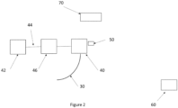
- the hook block apparatus 10 also includes rotation means for rotating the hook 30 relative to the lower portion 14 about a vertical axis. This rotation means is self-contained within the lower portion 14 and so not visible in Figure 1 . It is shown diagrammatically in Figure 2 .
- the rotation means comprises a first gear 40 provided at the connection of the hook 30 to the lower portion 14.
- An electric motor 42 has an output shaft 44 which is coupled to the first gear 40 such that operation of the motor 42 causes rotation of the hook 30. Power is supplied to the motor 42 from a sealed 12 volt battery.
- a second gear 46 interposes the first gear 40 and the output shaft 44 of the motor 42.
- the rotational output speed of the motor 42 and the gear ratios of the first and second gears are selected to allow slow rotating of the hook 30, such as less than 6 RPM.
- connection of the first gear 40 to the motor 42 impedes unintended rotation of the hook and any suspended load.
- a rotation sensor 50 is provided for sensing rotation and the direction of rotation of the hook 30.
- the rotation sensor 50 is connected to the motor 42 such that the motor 42 can apply a rotating force to the hook 30 in an opposite direction to that of any unintended rotation of the hook 30.
- the first gear 40 is selectively disengageable from the hook 30 so that the hook 30 is freely rotatable relative to the lower portion. This can be useful in the event of an electrical failure or the like.
- the rotation means is wirelessly operable from a remote location.
- the rotation means includes a receiver for wirelessly receiving signals from a remote transmitter.
- the receiver and transmitter are configured such that signals can be sent over a distance of at least 100 metres.
- the hook block apparatus 10 includes a portable device 60 which includes the transmitter for transmitting signals to the receiver 52.
- the portable device can be a remote control device or a smart phone or tablet which is configured using an app.
- the hook block apparatus includes a camera 70 which is orientated so as to sense the rotational orientation of the hook 30.
- the vision sensor can include a transmitter for transmitting an image of the hook 30 to the portable device 60.
- the hook block apparatus 10 can be configured to have a safe working load (swl) of at least 30 tonnes, most preferably 148 tonnes.
- the present invention allows safer rotational positioning of the suspended load from a remote location. It can also selectively allow or resist rotational movement of the suspended load.
Landscapes
- Engineering & Computer Science (AREA)
- Mechanical Engineering (AREA)
- Load-Engaging Elements For Cranes (AREA)
Description
- The present invention relates to hook block apparatus. In particular, but not exclusively, the present invention relates to hook block apparatus which allows remote rotating of the load.
- A hook block provides the connection between the lifting rope (or cable or chain) of a hoisting device, such as a crane, and the load. Typically, the hook block has a lower part to which a hook is fastened and an upper part in which sheaves, also referred to as pulleys, are arranged on a shaft. The lifting rope is reeved over the sheeves to provide a mechanical advantage that amplifies the force applied to the rope according to the pulley principle.
- Typically, the hook is rotatably connected to the lower part of the hook block via a bearing arrangement so that the suspended load may be rotated about a vertical axis. This allows the load to be rotationally moved to the desired orientation before depositing the load. For example, it is common for operators to manually handle the suspended load which represents a health and safety risk. Alternatively, a tag line can be attached to the load to allow an operator to rotate the load. However, this requires that the operator be laterally close to the suspended load and perhaps even under the suspended load. In the event of a catastrophic failure, the load could fall or tilt and impact the operator.
- There are also a number of disadvantages and dangers associated with the use of tag lines. The tag lines can easily become wrapped around an operator attempting to manoeuvre the load which can be extremely dangerous as the workman can then accidentally be lifted by the crane movements with serious injuries occurring. When a load is lowered this can also result in a large amount of slack in the tag line with this simply lying on the ground. With a large amount of slack tag line lying on the ground this can easily become entangled with other articles. The slack tag line can also become entangled with other workmen in the near vicinity who may accidentally walk over the tag line.
- Also, during movement of the suspended load, the load may impact an object which causes the load to rotate. This can be dangerous and it can take some time for the load to stop rotating in alternating directions and come to a stop.
- It is desirable to provide a hook block apparatus which allows rotational positioning of the suspended load. It is desirable to provide a hook block apparatus which allows rotational positioning of the suspended load from a remote location. It is desirable to provide a hook block apparatus which selectively allows or resists rotational movement of the suspended load.
- Document
US5071184A discloses a hook block apparatus according with the preamble of claim 1. - According to the present invention there is provided a hook block apparatus comprising:
- an upper portion comprising a sheave assembly for receiving a lifting rope of a hoisting device;
- a lower portion fixedly connected to the upper portion;
- a hook member which is rotatably connected to the lower portion;
- rotation means for rotating the hook member relative to the lower portion about a vertical axis,
- wherein the rotation means is selectively operable from a remote location.
- Optionally, the hook member is rotatably connected to the lower portion via a bearing arrangement.
- Optionally, the rotation means comprises a first gear provided at the connection of the hook member to the lower portion.
- Optionally, the rotation means comprises a motor having an output shaft which is coupled to the first gear such that operation of the motor causes rotation of the hook member.
- Optionally, the motor is an electric motor. Optionally, the motor is adapted to provide precise rotational positioning of the hook member. Optionally, the motor is a stepper motor or the like.
- In alternative embodiments, the motor may be a hydraulic motor or a pneumatic motor.
- Optionally, at least a second gear interposes the first gear and the output shaft of the motor. Optionally, at least one of the rotational output speed of the motor and the sizing of at least one of the first and second gears are configured to allow slow rotating of the hook member, such as less than 6 RPM.
- The rotation means is adapted to prevent or impede unintended rotation of the hook member.
- The hook block apparatus includes a rotation sensor for sensing rotation of the hook member. The rotation sensor is adapted to sense the direction of rotation.
- The rotation sensor is connected to the rotation means and the rotation means is adapted to apply a rotating force to the hook member in an opposite direction to that of unintended rotation of the hook member.
- The rotation means is selectively disengageable from the hook member such that the hook member is freely rotatable relative to the lower portion.
- Optionally, the rotation means is adapted to allow the hook member to be rotated to any orientation through 360 degrees.
- Optionally, the rotation means is wirelessly operable from a remote location.
- Optionally, the rotation means includes a receiver for wirelessly receiving signals from a remote transmitter. Optionally, the receiver and transmitter are configured such that signals can be sent over a distance of at least 20 metres, preferably at least 100 metres.
- Optionally, the hook block apparatus includes a portable device which includes the transmitter for transmitting signals to the receiver. Optionally, the portable device comprises a remote control device. Alternatively, the portable device may be a smart device such as a smart phone or tablet which is configured using an app.
- Optionally, the hook block apparatus includes at least one vision sensor, such as a camera. Optionally, the vision sensor is orientated so as to sense the rotational orientation of the hook member.
- Optionally, the vision sensor includes a transmitter for transmitting an image of the hook member to the portable device.
- Optionally, the hook block apparatus is configured to have a safe working load (swl) of at least 30 tonnes, preferably at least 50 tonnes, most preferably 150 tonnes.
- The invention will be described below, by way of example only, with reference to the accompanying drawings, in which:
-
Figure 1 is a (a) front view and a (b) side view of a hook block apparatus in accordance with the present invention; and -
Figure 2 is a diagrammatic view of the hook block apparatus ofFigure 1 . -
Figure 1 shows ahook block apparatus 10 comprising anupper portion 12 and alower portion 14. Theupper portion 12 comprises asheave assembly 20 for receiving a lifting rope of a hoisting device (not shown). Thelower portion 14 fixedly connected to, or integral with, theupper portion 12. Ahook 30 is rotatably connected to thelower portion 14 via abearing arrangement 32. - The
hook block apparatus 10 also includes rotation means for rotating thehook 30 relative to thelower portion 14 about a vertical axis. This rotation means is self-contained within thelower portion 14 and so not visible inFigure 1 . It is shown diagrammatically inFigure 2 . - The rotation means comprises a
first gear 40 provided at the connection of thehook 30 to thelower portion 14. Anelectric motor 42 has anoutput shaft 44 which is coupled to thefirst gear 40 such that operation of themotor 42 causes rotation of thehook 30. Power is supplied to themotor 42 from a sealed 12 volt battery. - A
second gear 46 interposes thefirst gear 40 and theoutput shaft 44 of themotor 42. The rotational output speed of themotor 42 and the gear ratios of the first and second gears are selected to allow slow rotating of thehook 30, such as less than 6 RPM. - The connection of the
first gear 40 to themotor 42 impedes unintended rotation of the hook and any suspended load. Also, arotation sensor 50 is provided for sensing rotation and the direction of rotation of thehook 30. Therotation sensor 50 is connected to themotor 42 such that themotor 42 can apply a rotating force to thehook 30 in an opposite direction to that of any unintended rotation of thehook 30. - The
first gear 40 is selectively disengageable from thehook 30 so that thehook 30 is freely rotatable relative to the lower portion. This can be useful in the event of an electrical failure or the like. - The rotation means is wirelessly operable from a remote location. The rotation means includes a receiver for wirelessly receiving signals from a remote transmitter. The receiver and transmitter are configured such that signals can be sent over a distance of at least 100 metres.
- The
hook block apparatus 10 includes aportable device 60 which includes the transmitter for transmitting signals to the receiver 52. The portable device can be a remote control device or a smart phone or tablet which is configured using an app. - The hook block apparatus includes a
camera 70 which is orientated so as to sense the rotational orientation of thehook 30. The vision sensor can include a transmitter for transmitting an image of thehook 30 to theportable device 60. - The
hook block apparatus 10 can be configured to have a safe working load (swl) of at least 30 tonnes, most preferably 148 tonnes. - The present invention allows safer rotational positioning of the suspended load from a remote location. It can also selectively allow or resist rotational movement of the suspended load.
- Various modifications and improvements can be made to the above without departing from the scope of the invention as defined by the claims.
Claims (10)
- A hook block apparatus (10) comprising:an upper portion (12) comprising a sheave assembly for receiving a lifting rope of a hoisting device;a lower portion (14) fixedly connected to the upper portion;a hook member (30) which is rotatably connected to the lower portion;rotation means (40, 42) for rotating the hook member relative to the lower portion about a vertical axis, wherein the rotation means is self contained within the lower portion and wherein the rotation means is selectively operable from a remote location;a rotation sensor (50) for sensing rotation of the hook member and adapted to sense the direction of rotation;wherein the rotation sensor is connected to the rotation means and the rotation means is adapted to apply a rotating force to the hook member in an opposite direction to that of unintended rotation of the hook member to prevent or impede unintended rotation of the hook member;characterized in thatthe rotation means is selectively disengageable from the hook member such that the hook member is freely rotatable relative to the lower portion.
- A hook block apparatus as claimed in Claim 1, wherein the hook member is rotatably connected to the lower portion via a bearing arrangement.
- A hook block apparatus as claimed in Claim 1 or 2, wherein the rotation means comprises a first gear (40) provided at the connection of the hook member to the lower portion and a motor (42) having an output shaft (44) which is coupled to the first gear such that operation of the motor causes rotation of the hook member.
- A hook block apparatus as claimed in Claim 3, wherein at least a second gear interposes the first gear and the output shaft of the motor.
- A hook block apparatus as claimed in Claim 4, wherein at least one of the rotational output speed of the motor and the sizing of at least one of the first and second gears are configured to allow slow rotating of the hook member.
- A hook block apparatus as claimed in any preceding claim, wherein the rotation means is wirelessly operable from a remote location.
- A hook block apparatus as claimed in Claim 6, wherein the rotation means includes a receiver for wirelessly receiving signals from a remote transmitter, and wherein the receiver and transmitter are configured such that signals can be sent over a distance of at least 20 metres.
- A hook block apparatus as claimed in any preceding claim, wherein the hook block apparatus includes at least one vision sensor.
- A hook block apparatus as claimed in Claim 8, wherein the vision sensor is orientated so as to sense the rotational orientation of the hook member.
- A hook block apparatus as claimed in Claim 8 or 9, wherein the vision sensor includes a transmitter for transmitting an image of the hook member to a portable device (60).
Applications Claiming Priority (1)
| Application Number | Priority Date | Filing Date | Title |
|---|---|---|---|
| GB2001252.2A GB2593665A (en) | 2020-01-29 | 2020-01-29 | Improved Hook block |
Publications (3)
| Publication Number | Publication Date |
|---|---|
| EP3858780A1 EP3858780A1 (en) | 2021-08-04 |
| EP3858780B1 true EP3858780B1 (en) | 2025-05-07 |
| EP3858780C0 EP3858780C0 (en) | 2025-05-07 |
Family
ID=69725984
Family Applications (1)
| Application Number | Title | Priority Date | Filing Date |
|---|---|---|---|
| EP21154390.5A Active EP3858780B1 (en) | 2020-01-29 | 2021-01-29 | Improved hook block |
Country Status (3)
| Country | Link |
|---|---|
| EP (1) | EP3858780B1 (en) |
| ES (1) | ES3034190T3 (en) |
| GB (1) | GB2593665A (en) |
Families Citing this family (1)
| Publication number | Priority date | Publication date | Assignee | Title |
|---|---|---|---|---|
| CN118387755B (en) * | 2024-06-24 | 2024-09-03 | 泰州市众擎金属制品有限公司 | Material transferring, lifting and hoisting device |
Family Cites Families (15)
| Publication number | Priority date | Publication date | Assignee | Title |
|---|---|---|---|---|
| FR1229282A (en) * | 1958-07-17 | 1960-09-06 | Rotary tool support or load device | |
| DE3234395A1 (en) * | 1982-09-16 | 1984-03-22 | F.T. Industries Co., Ltd., Fukuyama, Hiroshima | Radio-controlled, pivotable load hook arrangement |
| JP2577694Y2 (en) * | 1989-05-17 | 1998-07-30 | 山九株式会社 | Rotary lifting hook device |
| FR2649966B1 (en) * | 1989-07-18 | 1991-09-27 | Potain Sa | MOTORIZED LOAD ROTATING DEVICE, SELF-POWERED, FOR CABLE LIFTING APPARATUS |
| JPH09165189A (en) * | 1995-12-19 | 1997-06-24 | Tokyu Constr Co Ltd | Turning controlling device and method for sheave block |
| KR100389563B1 (en) * | 2003-03-28 | 2003-06-28 | Byung Kwan Jean | Hook device for crane |
| US7656459B2 (en) * | 2006-04-20 | 2010-02-02 | Pacific Systems Solution Llc | Crane hook and trolley camera system |
| WO2010150336A1 (en) * | 2009-06-22 | 2010-12-29 | 株式会社青木機械 | Lifting hook device |
| CN202245713U (en) * | 2011-08-31 | 2012-05-30 | 无锡汇力机械制造有限公司 | Rotary lifting hook for crane |
| JP2014237503A (en) * | 2013-06-06 | 2014-12-18 | 清水建設株式会社 | Crane hook |
| CN204297927U (en) * | 2014-08-18 | 2015-04-29 | 河南省中杰起重机有限公司 | A kind of electric rotary locating hook and use the hoisting crane of this suspension hook |
| CN204689371U (en) * | 2015-04-25 | 2015-10-07 | 河南华北起重吊钩有限公司 | A kind of Based Intelligent Control shackle hook |
| JP6791714B2 (en) * | 2016-10-13 | 2020-11-25 | 古河ユニック株式会社 | Hook device for mobile crane and mobile crane equipped with it |
| KR102044521B1 (en) * | 2017-07-04 | 2019-12-02 | 김영환 | Apparatus for controlling rotation of crane hook |
| CN208916616U (en) * | 2018-08-31 | 2019-05-31 | 中昇建机(南京)重工有限公司 | A kind of crane hook and visualization lifting derrick crane |
-
2020
- 2020-01-29 GB GB2001252.2A patent/GB2593665A/en not_active Withdrawn
-
2021
- 2021-01-29 ES ES21154390T patent/ES3034190T3/en active Active
- 2021-01-29 EP EP21154390.5A patent/EP3858780B1/en active Active
Also Published As
| Publication number | Publication date |
|---|---|
| EP3858780A1 (en) | 2021-08-04 |
| EP3858780C0 (en) | 2025-05-07 |
| GB202001252D0 (en) | 2020-03-11 |
| ES3034190T3 (en) | 2025-08-13 |
| GB2593665A (en) | 2021-10-06 |
Similar Documents
| Publication | Publication Date | Title |
|---|---|---|
| US11285346B2 (en) | Personal safety apparatus and system | |
| US4787524A (en) | Overload protection system for a crane | |
| US20160152451A1 (en) | Hybrid Crane | |
| CS354690A2 (en) | Energetically self-feeding motorized mechanism for rotating loads suspended on rope lifting devices | |
| US4280628A (en) | Anti-two block system | |
| EP3466865B1 (en) | Method for securing a lifting boom crane and associated crane | |
| EP3858780A1 (en) | Improved hook block | |
| CN114845949A (en) | Load guide device for mounting to a crane | |
| US6517131B1 (en) | Suspended load rotary device | |
| US20010048100A1 (en) | Tahoe rescue tool - rescue hoist | |
| EP0629577A1 (en) | Load-lifting and orienting apparatus | |
| US11795037B2 (en) | Overhead travelling crane assembly | |
| KR20100097863A (en) | Tower crane capable of positioning structural elements | |
| US2524189A (en) | Hook structure | |
| CN214527652U (en) | Hoist for building couple safety monitoring device | |
| US20240228236A1 (en) | Crane | |
| KR102365185B1 (en) | Boom Length Detection Device of Hydraulic Crane Multi-Stage Boom device with Boom Length Sensor | |
| KR101003841B1 (en) | Rotatable crane hook device | |
| JP2003095585A (en) | Detachable drive for chain blocks and manual chain blocks | |
| KR20240059451A (en) | Hoisting device | |
| NL2026970B1 (en) | Crane for handling a cable-suspended load, method of manufacturing such a crane and use of such a crane. | |
| CN211895806U (en) | Pulley mechanism for offshore platform crane | |
| US4252243A (en) | Crane safety device | |
| KR20190121005A (en) | Apparatus for unwinding cover membrane | |
| US3658188A (en) | Safety control for load line |
Legal Events
| Date | Code | Title | Description |
|---|---|---|---|
| PUAI | Public reference made under article 153(3) epc to a published international application that has entered the european phase |
Free format text: ORIGINAL CODE: 0009012 |
|
| STAA | Information on the status of an ep patent application or granted ep patent |
Free format text: STATUS: THE APPLICATION HAS BEEN PUBLISHED |
|
| AK | Designated contracting states |
Kind code of ref document: A1 Designated state(s): AL AT BE BG CH CY CZ DE DK EE ES FI FR GB GR HR HU IE IS IT LI LT LU LV MC MK MT NL NO PL PT RO RS SE SI SK SM TR |
|
| STAA | Information on the status of an ep patent application or granted ep patent |
Free format text: STATUS: REQUEST FOR EXAMINATION WAS MADE |
|
| 17P | Request for examination filed |
Effective date: 20220201 |
|
| RBV | Designated contracting states (corrected) |
Designated state(s): AL AT BE BG CH CY CZ DE DK EE ES FI FR GB GR HR HU IE IS IT LI LT LU LV MC MK MT NL NO PL PT RO RS SE SI SK SM TR |
|
| STAA | Information on the status of an ep patent application or granted ep patent |
Free format text: STATUS: EXAMINATION IS IN PROGRESS |
|
| 17Q | First examination report despatched |
Effective date: 20230323 |
|
| GRAP | Despatch of communication of intention to grant a patent |
Free format text: ORIGINAL CODE: EPIDOSNIGR1 |
|
| STAA | Information on the status of an ep patent application or granted ep patent |
Free format text: STATUS: GRANT OF PATENT IS INTENDED |
|
| INTG | Intention to grant announced |
Effective date: 20241202 |
|
| GRAS | Grant fee paid |
Free format text: ORIGINAL CODE: EPIDOSNIGR3 |
|
| GRAA | (expected) grant |
Free format text: ORIGINAL CODE: 0009210 |
|
| STAA | Information on the status of an ep patent application or granted ep patent |
Free format text: STATUS: THE PATENT HAS BEEN GRANTED |
|
| AK | Designated contracting states |
Kind code of ref document: B1 Designated state(s): AL AT BE BG CH CY CZ DE DK EE ES FI FR GB GR HR HU IE IS IT LI LT LU LV MC MK MT NL NO PL PT RO RS SE SI SK SM TR |
|
| REG | Reference to a national code |
Ref country code: GB Ref legal event code: FG4D |
|
| REG | Reference to a national code |
Ref country code: CH Ref legal event code: EP |
|
| REG | Reference to a national code |
Ref country code: DE Ref legal event code: R096 Ref document number: 602021030217 Country of ref document: DE |
|
| REG | Reference to a national code |
Ref country code: IE Ref legal event code: FG4D |
|
| U01 | Request for unitary effect filed |
Effective date: 20250606 |
|
| REG | Reference to a national code |
Ref country code: ES Ref legal event code: FG2A Ref document number: 3034190 Country of ref document: ES Kind code of ref document: T3 Effective date: 20250813 |
|
| U07 | Unitary effect registered |
Designated state(s): AT BE BG DE DK EE FI FR IT LT LU LV MT NL PT RO SE SI Effective date: 20250718 |
|
| PG25 | Lapsed in a contracting state [announced via postgrant information from national office to epo] |
Ref country code: NO Free format text: LAPSE BECAUSE OF FAILURE TO SUBMIT A TRANSLATION OF THE DESCRIPTION OR TO PAY THE FEE WITHIN THE PRESCRIBED TIME-LIMIT Effective date: 20250807 Ref country code: GR Free format text: LAPSE BECAUSE OF FAILURE TO SUBMIT A TRANSLATION OF THE DESCRIPTION OR TO PAY THE FEE WITHIN THE PRESCRIBED TIME-LIMIT Effective date: 20250808 |
|
| PG25 | Lapsed in a contracting state [announced via postgrant information from national office to epo] |
Ref country code: PL Free format text: LAPSE BECAUSE OF FAILURE TO SUBMIT A TRANSLATION OF THE DESCRIPTION OR TO PAY THE FEE WITHIN THE PRESCRIBED TIME-LIMIT Effective date: 20250507 |
|
| PG25 | Lapsed in a contracting state [announced via postgrant information from national office to epo] |
Ref country code: HR Free format text: LAPSE BECAUSE OF FAILURE TO SUBMIT A TRANSLATION OF THE DESCRIPTION OR TO PAY THE FEE WITHIN THE PRESCRIBED TIME-LIMIT Effective date: 20250507 |
|
| PG25 | Lapsed in a contracting state [announced via postgrant information from national office to epo] |
Ref country code: RS Free format text: LAPSE BECAUSE OF FAILURE TO SUBMIT A TRANSLATION OF THE DESCRIPTION OR TO PAY THE FEE WITHIN THE PRESCRIBED TIME-LIMIT Effective date: 20250807 |
|
| PG25 | Lapsed in a contracting state [announced via postgrant information from national office to epo] |
Ref country code: IS Free format text: LAPSE BECAUSE OF FAILURE TO SUBMIT A TRANSLATION OF THE DESCRIPTION OR TO PAY THE FEE WITHIN THE PRESCRIBED TIME-LIMIT Effective date: 20250907 |
|
| PG25 | Lapsed in a contracting state [announced via postgrant information from national office to epo] |
Ref country code: SM Free format text: LAPSE BECAUSE OF FAILURE TO SUBMIT A TRANSLATION OF THE DESCRIPTION OR TO PAY THE FEE WITHIN THE PRESCRIBED TIME-LIMIT Effective date: 20250507 |
|
| PG25 | Lapsed in a contracting state [announced via postgrant information from national office to epo] |
Ref country code: CZ Free format text: LAPSE BECAUSE OF FAILURE TO SUBMIT A TRANSLATION OF THE DESCRIPTION OR TO PAY THE FEE WITHIN THE PRESCRIBED TIME-LIMIT Effective date: 20250507 |
|
| PG25 | Lapsed in a contracting state [announced via postgrant information from national office to epo] |
Ref country code: SK Free format text: LAPSE BECAUSE OF FAILURE TO SUBMIT A TRANSLATION OF THE DESCRIPTION OR TO PAY THE FEE WITHIN THE PRESCRIBED TIME-LIMIT Effective date: 20250507 |
|
| U20 | Renewal fee for the european patent with unitary effect paid |
Year of fee payment: 6 Effective date: 20260112 |
|
| PLBE | No opposition filed within time limit |
Free format text: ORIGINAL CODE: 0009261 |
|
| STAA | Information on the status of an ep patent application or granted ep patent |
Free format text: STATUS: NO OPPOSITION FILED WITHIN TIME LIMIT |
|
| REG | Reference to a national code |
Ref country code: CH Ref legal event code: L10 Free format text: ST27 STATUS EVENT CODE: U-0-0-L10-L00 (AS PROVIDED BY THE NATIONAL OFFICE) Effective date: 20260318 |
|
| PGFP | Annual fee paid to national office [announced via postgrant information from national office to epo] |
Ref country code: GB Payment date: 20260112 Year of fee payment: 6 |
|
| PGFP | Annual fee paid to national office [announced via postgrant information from national office to epo] |
Ref country code: ES Payment date: 20260217 Year of fee payment: 6 |
|
| 26N | No opposition filed |
Effective date: 20260210 |