EP3858720A1 - Battery attaching/detaching structure for saddle-type vehicle - Google Patents
Battery attaching/detaching structure for saddle-type vehicle Download PDFInfo
- Publication number
- EP3858720A1 EP3858720A1 EP18935576.1A EP18935576A EP3858720A1 EP 3858720 A1 EP3858720 A1 EP 3858720A1 EP 18935576 A EP18935576 A EP 18935576A EP 3858720 A1 EP3858720 A1 EP 3858720A1
- Authority
- EP
- European Patent Office
- Prior art keywords
- battery
- case
- batteries
- operation lever
- side terminals
- Prior art date
- Legal status (The legal status is an assumption and is not a legal conclusion. Google has not performed a legal analysis and makes no representation as to the accuracy of the status listed.)
- Granted
Links
Images


Classifications
-
- B—PERFORMING OPERATIONS; TRANSPORTING
- B60—VEHICLES IN GENERAL
- B60L—PROPULSION OF ELECTRICALLY-PROPELLED VEHICLES; SUPPLYING ELECTRIC POWER FOR AUXILIARY EQUIPMENT OF ELECTRICALLY-PROPELLED VEHICLES; ELECTRODYNAMIC BRAKE SYSTEMS FOR VEHICLES IN GENERAL; MAGNETIC SUSPENSION OR LEVITATION FOR VEHICLES; MONITORING OPERATING VARIABLES OF ELECTRICALLY-PROPELLED VEHICLES; ELECTRIC SAFETY DEVICES FOR ELECTRICALLY-PROPELLED VEHICLES
- B60L50/00—Electric propulsion with power supplied within the vehicle
- B60L50/50—Electric propulsion with power supplied within the vehicle using propulsion power supplied by batteries or fuel cells
- B60L50/60—Electric propulsion with power supplied within the vehicle using propulsion power supplied by batteries or fuel cells using power supplied by batteries
- B60L50/64—Constructional details of batteries specially adapted for electric vehicles
-
- B—PERFORMING OPERATIONS; TRANSPORTING
- B62—LAND VEHICLES FOR TRAVELLING OTHERWISE THAN ON RAILS
- B62J—CYCLE SADDLES OR SEATS; AUXILIARY DEVICES OR ACCESSORIES SPECIALLY ADAPTED TO CYCLES AND NOT OTHERWISE PROVIDED FOR, e.g. ARTICLE CARRIERS OR CYCLE PROTECTORS
- B62J43/00—Arrangements of batteries
- B62J43/20—Arrangements of batteries characterised by the mounting
- B62J43/23—Arrangements of batteries characterised by the mounting dismounted when charging
-
- B—PERFORMING OPERATIONS; TRANSPORTING
- B60—VEHICLES IN GENERAL
- B60K—ARRANGEMENT OR MOUNTING OF PROPULSION UNITS OR OF TRANSMISSIONS IN VEHICLES; ARRANGEMENT OR MOUNTING OF PLURAL DIVERSE PRIME-MOVERS IN VEHICLES; AUXILIARY DRIVES FOR VEHICLES; INSTRUMENTATION OR DASHBOARDS FOR VEHICLES; ARRANGEMENTS IN CONNECTION WITH COOLING, AIR INTAKE, GAS EXHAUST OR FUEL SUPPLY OF PROPULSION UNITS IN VEHICLES
- B60K1/00—Arrangement or mounting of electrical propulsion units
- B60K1/04—Arrangement or mounting of electrical propulsion units of the electric storage means for propulsion
-
- B—PERFORMING OPERATIONS; TRANSPORTING
- B60—VEHICLES IN GENERAL
- B60L—PROPULSION OF ELECTRICALLY-PROPELLED VEHICLES; SUPPLYING ELECTRIC POWER FOR AUXILIARY EQUIPMENT OF ELECTRICALLY-PROPELLED VEHICLES; ELECTRODYNAMIC BRAKE SYSTEMS FOR VEHICLES IN GENERAL; MAGNETIC SUSPENSION OR LEVITATION FOR VEHICLES; MONITORING OPERATING VARIABLES OF ELECTRICALLY-PROPELLED VEHICLES; ELECTRIC SAFETY DEVICES FOR ELECTRICALLY-PROPELLED VEHICLES
- B60L50/00—Electric propulsion with power supplied within the vehicle
- B60L50/50—Electric propulsion with power supplied within the vehicle using propulsion power supplied by batteries or fuel cells
- B60L50/60—Electric propulsion with power supplied within the vehicle using propulsion power supplied by batteries or fuel cells using power supplied by batteries
- B60L50/66—Arrangements of batteries
-
- B—PERFORMING OPERATIONS; TRANSPORTING
- B60—VEHICLES IN GENERAL
- B60L—PROPULSION OF ELECTRICALLY-PROPELLED VEHICLES; SUPPLYING ELECTRIC POWER FOR AUXILIARY EQUIPMENT OF ELECTRICALLY-PROPELLED VEHICLES; ELECTRODYNAMIC BRAKE SYSTEMS FOR VEHICLES IN GENERAL; MAGNETIC SUSPENSION OR LEVITATION FOR VEHICLES; MONITORING OPERATING VARIABLES OF ELECTRICALLY-PROPELLED VEHICLES; ELECTRIC SAFETY DEVICES FOR ELECTRICALLY-PROPELLED VEHICLES
- B60L53/00—Methods of charging batteries, specially adapted for electric vehicles; Charging stations or on-board charging equipment therefor; Exchange of energy storage elements in electric vehicles
- B60L53/80—Exchanging energy storage elements, e.g. removable batteries
-
- B—PERFORMING OPERATIONS; TRANSPORTING
- B62—LAND VEHICLES FOR TRAVELLING OTHERWISE THAN ON RAILS
- B62J—CYCLE SADDLES OR SEATS; AUXILIARY DEVICES OR ACCESSORIES SPECIALLY ADAPTED TO CYCLES AND NOT OTHERWISE PROVIDED FOR, e.g. ARTICLE CARRIERS OR CYCLE PROTECTORS
- B62J43/00—Arrangements of batteries
- B62J43/10—Arrangements of batteries for propulsion
- B62J43/16—Arrangements of batteries for propulsion on motorcycles or the like
-
- B—PERFORMING OPERATIONS; TRANSPORTING
- B62—LAND VEHICLES FOR TRAVELLING OTHERWISE THAN ON RAILS
- B62J—CYCLE SADDLES OR SEATS; AUXILIARY DEVICES OR ACCESSORIES SPECIALLY ADAPTED TO CYCLES AND NOT OTHERWISE PROVIDED FOR, e.g. ARTICLE CARRIERS OR CYCLE PROTECTORS
- B62J9/00—Containers specially adapted for cycles, e.g. panniers or saddle bags
- B62J9/10—Containers specially adapted for cycles, e.g. panniers or saddle bags integrated with the cycle
- B62J9/14—Containers specially adapted for cycles, e.g. panniers or saddle bags integrated with the cycle under the saddle
-
- H—ELECTRICITY
- H01—ELECTRIC ELEMENTS
- H01M—PROCESSES OR MEANS, e.g. BATTERIES, FOR THE DIRECT CONVERSION OF CHEMICAL ENERGY INTO ELECTRICAL ENERGY
- H01M10/00—Secondary cells; Manufacture thereof
- H01M10/04—Construction or manufacture in general
- H01M10/0481—Compression means other than compression means for stacks of electrodes and separators
-
- H—ELECTRICITY
- H01—ELECTRIC ELEMENTS
- H01M—PROCESSES OR MEANS, e.g. BATTERIES, FOR THE DIRECT CONVERSION OF CHEMICAL ENERGY INTO ELECTRICAL ENERGY
- H01M50/00—Constructional details or processes of manufacture of the non-active parts of electrochemical cells other than fuel cells, e.g. hybrid cells
- H01M50/20—Mountings; Secondary casings or frames; Racks, modules or packs; Suspension devices; Shock absorbers; Transport or carrying devices; Holders
- H01M50/202—Casings or frames around the primary casing of a single cell or a single battery
-
- H—ELECTRICITY
- H01—ELECTRIC ELEMENTS
- H01M—PROCESSES OR MEANS, e.g. BATTERIES, FOR THE DIRECT CONVERSION OF CHEMICAL ENERGY INTO ELECTRICAL ENERGY
- H01M50/00—Constructional details or processes of manufacture of the non-active parts of electrochemical cells other than fuel cells, e.g. hybrid cells
- H01M50/20—Mountings; Secondary casings or frames; Racks, modules or packs; Suspension devices; Shock absorbers; Transport or carrying devices; Holders
- H01M50/244—Secondary casings; Racks; Suspension devices; Carrying devices; Holders characterised by their mounting method
-
- H—ELECTRICITY
- H01—ELECTRIC ELEMENTS
- H01M—PROCESSES OR MEANS, e.g. BATTERIES, FOR THE DIRECT CONVERSION OF CHEMICAL ENERGY INTO ELECTRICAL ENERGY
- H01M50/00—Constructional details or processes of manufacture of the non-active parts of electrochemical cells other than fuel cells, e.g. hybrid cells
- H01M50/20—Mountings; Secondary casings or frames; Racks, modules or packs; Suspension devices; Shock absorbers; Transport or carrying devices; Holders
- H01M50/249—Mountings; Secondary casings or frames; Racks, modules or packs; Suspension devices; Shock absorbers; Transport or carrying devices; Holders specially adapted for aircraft or vehicles, e.g. cars or trains
-
- H—ELECTRICITY
- H01—ELECTRIC ELEMENTS
- H01M—PROCESSES OR MEANS, e.g. BATTERIES, FOR THE DIRECT CONVERSION OF CHEMICAL ENERGY INTO ELECTRICAL ENERGY
- H01M50/00—Constructional details or processes of manufacture of the non-active parts of electrochemical cells other than fuel cells, e.g. hybrid cells
- H01M50/20—Mountings; Secondary casings or frames; Racks, modules or packs; Suspension devices; Shock absorbers; Transport or carrying devices; Holders
- H01M50/289—Mountings; Secondary casings or frames; Racks, modules or packs; Suspension devices; Shock absorbers; Transport or carrying devices; Holders characterised by spacing elements or positioning means within frames, racks or packs
-
- H—ELECTRICITY
- H01—ELECTRIC ELEMENTS
- H01M—PROCESSES OR MEANS, e.g. BATTERIES, FOR THE DIRECT CONVERSION OF CHEMICAL ENERGY INTO ELECTRICAL ENERGY
- H01M50/00—Constructional details or processes of manufacture of the non-active parts of electrochemical cells other than fuel cells, e.g. hybrid cells
- H01M50/20—Mountings; Secondary casings or frames; Racks, modules or packs; Suspension devices; Shock absorbers; Transport or carrying devices; Holders
- H01M50/296—Mountings; Secondary casings or frames; Racks, modules or packs; Suspension devices; Shock absorbers; Transport or carrying devices; Holders characterised by terminals of battery packs
-
- B—PERFORMING OPERATIONS; TRANSPORTING
- B60—VEHICLES IN GENERAL
- B60K—ARRANGEMENT OR MOUNTING OF PROPULSION UNITS OR OF TRANSMISSIONS IN VEHICLES; ARRANGEMENT OR MOUNTING OF PLURAL DIVERSE PRIME-MOVERS IN VEHICLES; AUXILIARY DRIVES FOR VEHICLES; INSTRUMENTATION OR DASHBOARDS FOR VEHICLES; ARRANGEMENTS IN CONNECTION WITH COOLING, AIR INTAKE, GAS EXHAUST OR FUEL SUPPLY OF PROPULSION UNITS IN VEHICLES
- B60K1/00—Arrangement or mounting of electrical propulsion units
- B60K1/04—Arrangement or mounting of electrical propulsion units of the electric storage means for propulsion
- B60K2001/0405—Arrangement or mounting of electrical propulsion units of the electric storage means for propulsion characterised by their position
-
- B—PERFORMING OPERATIONS; TRANSPORTING
- B60—VEHICLES IN GENERAL
- B60K—ARRANGEMENT OR MOUNTING OF PROPULSION UNITS OR OF TRANSMISSIONS IN VEHICLES; ARRANGEMENT OR MOUNTING OF PLURAL DIVERSE PRIME-MOVERS IN VEHICLES; AUXILIARY DRIVES FOR VEHICLES; INSTRUMENTATION OR DASHBOARDS FOR VEHICLES; ARRANGEMENTS IN CONNECTION WITH COOLING, AIR INTAKE, GAS EXHAUST OR FUEL SUPPLY OF PROPULSION UNITS IN VEHICLES
- B60K1/00—Arrangement or mounting of electrical propulsion units
- B60K1/04—Arrangement or mounting of electrical propulsion units of the electric storage means for propulsion
- B60K2001/0455—Removal or replacement of the energy storages
- B60K2001/0466—Removal or replacement of the energy storages from above
-
- B—PERFORMING OPERATIONS; TRANSPORTING
- B60—VEHICLES IN GENERAL
- B60K—ARRANGEMENT OR MOUNTING OF PROPULSION UNITS OR OF TRANSMISSIONS IN VEHICLES; ARRANGEMENT OR MOUNTING OF PLURAL DIVERSE PRIME-MOVERS IN VEHICLES; AUXILIARY DRIVES FOR VEHICLES; INSTRUMENTATION OR DASHBOARDS FOR VEHICLES; ARRANGEMENTS IN CONNECTION WITH COOLING, AIR INTAKE, GAS EXHAUST OR FUEL SUPPLY OF PROPULSION UNITS IN VEHICLES
- B60K1/00—Arrangement or mounting of electrical propulsion units
- B60K1/04—Arrangement or mounting of electrical propulsion units of the electric storage means for propulsion
- B60K2001/0455—Removal or replacement of the energy storages
- B60K2001/0494—Removal or replacement of the energy storages with arrangements for sliding
-
- B—PERFORMING OPERATIONS; TRANSPORTING
- B60—VEHICLES IN GENERAL
- B60Y—INDEXING SCHEME RELATING TO ASPECTS CROSS-CUTTING VEHICLE TECHNOLOGY
- B60Y2200/00—Type of vehicle
- B60Y2200/10—Road Vehicles
- B60Y2200/12—Motorcycles, Trikes; Quads; Scooters
- B60Y2200/126—Scooters
-
- B—PERFORMING OPERATIONS; TRANSPORTING
- B62—LAND VEHICLES FOR TRAVELLING OTHERWISE THAN ON RAILS
- B62J—CYCLE SADDLES OR SEATS; AUXILIARY DEVICES OR ACCESSORIES SPECIALLY ADAPTED TO CYCLES AND NOT OTHERWISE PROVIDED FOR, e.g. ARTICLE CARRIERS OR CYCLE PROTECTORS
- B62J1/00—Saddles or other seats for cycles; Arrangement thereof; Component parts
- B62J1/12—Box-shaped seats; Bench-type seats, e.g. dual or twin seats
-
- B—PERFORMING OPERATIONS; TRANSPORTING
- B62—LAND VEHICLES FOR TRAVELLING OTHERWISE THAN ON RAILS
- B62K—CYCLES; CYCLE FRAMES; CYCLE STEERING DEVICES; RIDER-OPERATED TERMINAL CONTROLS SPECIALLY ADAPTED FOR CYCLES; CYCLE AXLE SUSPENSIONS; CYCLE SIDECARS, FORECARS, OR THE LIKE
- B62K2202/00—Motorised scooters
-
- B—PERFORMING OPERATIONS; TRANSPORTING
- B62—LAND VEHICLES FOR TRAVELLING OTHERWISE THAN ON RAILS
- B62K—CYCLES; CYCLE FRAMES; CYCLE STEERING DEVICES; RIDER-OPERATED TERMINAL CONTROLS SPECIALLY ADAPTED FOR CYCLES; CYCLE AXLE SUSPENSIONS; CYCLE SIDECARS, FORECARS, OR THE LIKE
- B62K2204/00—Adaptations for driving cycles by electric motor
-
- H—ELECTRICITY
- H01—ELECTRIC ELEMENTS
- H01M—PROCESSES OR MEANS, e.g. BATTERIES, FOR THE DIRECT CONVERSION OF CHEMICAL ENERGY INTO ELECTRICAL ENERGY
- H01M2220/00—Batteries for particular applications
- H01M2220/20—Batteries in motive systems, e.g. vehicle, ship, plane
-
- Y—GENERAL TAGGING OF NEW TECHNOLOGICAL DEVELOPMENTS; GENERAL TAGGING OF CROSS-SECTIONAL TECHNOLOGIES SPANNING OVER SEVERAL SECTIONS OF THE IPC; TECHNICAL SUBJECTS COVERED BY FORMER USPC CROSS-REFERENCE ART COLLECTIONS [XRACs] AND DIGESTS
- Y02—TECHNOLOGIES OR APPLICATIONS FOR MITIGATION OR ADAPTATION AGAINST CLIMATE CHANGE
- Y02E—REDUCTION OF GREENHOUSE GAS [GHG] EMISSIONS, RELATED TO ENERGY GENERATION, TRANSMISSION OR DISTRIBUTION
- Y02E60/00—Enabling technologies; Technologies with a potential or indirect contribution to GHG emissions mitigation
- Y02E60/10—Energy storage using batteries
-
- Y—GENERAL TAGGING OF NEW TECHNOLOGICAL DEVELOPMENTS; GENERAL TAGGING OF CROSS-SECTIONAL TECHNOLOGIES SPANNING OVER SEVERAL SECTIONS OF THE IPC; TECHNICAL SUBJECTS COVERED BY FORMER USPC CROSS-REFERENCE ART COLLECTIONS [XRACs] AND DIGESTS
- Y02—TECHNOLOGIES OR APPLICATIONS FOR MITIGATION OR ADAPTATION AGAINST CLIMATE CHANGE
- Y02P—CLIMATE CHANGE MITIGATION TECHNOLOGIES IN THE PRODUCTION OR PROCESSING OF GOODS
- Y02P70/00—Climate change mitigation technologies in the production process for final industrial or consumer products
- Y02P70/50—Manufacturing or production processes characterised by the final manufactured product
-
- Y—GENERAL TAGGING OF NEW TECHNOLOGICAL DEVELOPMENTS; GENERAL TAGGING OF CROSS-SECTIONAL TECHNOLOGIES SPANNING OVER SEVERAL SECTIONS OF THE IPC; TECHNICAL SUBJECTS COVERED BY FORMER USPC CROSS-REFERENCE ART COLLECTIONS [XRACs] AND DIGESTS
- Y02—TECHNOLOGIES OR APPLICATIONS FOR MITIGATION OR ADAPTATION AGAINST CLIMATE CHANGE
- Y02T—CLIMATE CHANGE MITIGATION TECHNOLOGIES RELATED TO TRANSPORTATION
- Y02T10/00—Road transport of goods or passengers
- Y02T10/60—Other road transportation technologies with climate change mitigation effect
- Y02T10/70—Energy storage systems for electromobility, e.g. batteries
-
- Y—GENERAL TAGGING OF NEW TECHNOLOGICAL DEVELOPMENTS; GENERAL TAGGING OF CROSS-SECTIONAL TECHNOLOGIES SPANNING OVER SEVERAL SECTIONS OF THE IPC; TECHNICAL SUBJECTS COVERED BY FORMER USPC CROSS-REFERENCE ART COLLECTIONS [XRACs] AND DIGESTS
- Y02—TECHNOLOGIES OR APPLICATIONS FOR MITIGATION OR ADAPTATION AGAINST CLIMATE CHANGE
- Y02T—CLIMATE CHANGE MITIGATION TECHNOLOGIES RELATED TO TRANSPORTATION
- Y02T10/00—Road transport of goods or passengers
- Y02T10/60—Other road transportation technologies with climate change mitigation effect
- Y02T10/7072—Electromobility specific charging systems or methods for batteries, ultracapacitors, supercapacitors or double-layer capacitors
Definitions
- the present invention relates to a battery attaching/detaching structure for a saddle-type vehicle, and more particularly to a battery attaching/detaching structure for a saddle-type vehicle applicable to a portable battery detachably stored in a body of the saddle-type electric vehicle and a battery storage portion.
- Patent Literature 1 discloses a configuration of a scooter-type electric vehicle having a low floor between a steering handle and a seat, in which two batteries are stored below an openable/closable seat.
- the two batteries having a substantially rectangular parallelepiped shape elongated in the vertical direction of the vehicle body are stored in two storing recesses arranged adjacent to each other in the longitudinal direction of the vehicle body, and when the batteries are stored in predetermined positions, the connection terminals on the battery side and the connection terminals on the vehicle body side are engaged with each other.
- Patent Literature 1 WO 2012/043518 A1
- connection terminals are engaged by storing batteries in storing recesses as in Patent Literature 1
- a configuration capable of maintaining a good electrical connection while holding batteries in predetermined positions by a holding mechanism there has been a demand for a configuration capable of maintaining a good electrical connection while holding batteries in predetermined positions by a holding mechanism.
- a battery attaching/detaching structure for a saddle-type vehicle including a plurality of substantially rectangular parallelepiped batteries (B) for supplying electric power to a power source of the saddle-type vehicle (1); a battery case (40) in which the batteries (B) are stored; battery-side terminals (75) provided on lower surfaces (107) of the batteries (B); and case-side terminals (90) engaged with the battery-side terminals (75), comprises terminal holders (74) that support the case-side terminals (90) such that the case-side terminals (90) are movable between a connected position (U) where the case-side terminals (90) are connected to the battery-side terminals (75) and a retracted position (D) where the case-side terminals (90) are separated from the battery-side terminals (75), wherein between the case-side terminals (90) and the terminal holders (74), springs (97) for urging the case-side terminal
- the present invention has a second feature in that the battery attaching/detaching structure for a saddle-type vehicle further includes: a single operation lever (60) that, when pushed downward in a state where the batteries (B) are stored in the battery case (40), limits vertical movement of the batteries (B); and a link mechanism (L) that connects the operation lever (60) and the terminal holders (74).
- a single operation lever (60) that, when pushed downward in a state where the batteries (B) are stored in the battery case (40), limits vertical movement of the batteries (B); and a link mechanism (L) that connects the operation lever (60) and the terminal holders (74).
- the present invention has a third feature in that the operation lever (60) is configured to be vertically slidable along a longitudinal direction of the batteries (B), and the battery attaching/detaching structure for a saddle-type vehicle further includes a pressing holder (45) that is swingable and presses upper surfaces (102) of the batteries (60) when the operation lever (60) is moved to a lowermost position.
- the present invention has a fourth feature in that the battery case (40) is disposed below a seat (23) that is openable/closable and that is provided in the saddle-type vehicle (1), and a boss (84) positioned above the operation lever (60) is provided on a bottom surface of the seat (23).
- the present invention has a fifth feature in that the boss (84) is not in contact with the operation lever (60) in a state where the operation lever (60) is pushed down to a predetermined lowermost position.
- the present invention has a sixth feature in that the terminal holders (74) are plate members that are substantially U-shaped and cover lower portions of the case-side terminals (90), the terminal holders (74) and the case-side terminals (90) are configured to be slidable in a vertical direction when support shafts (98) that are cylindrical and extend downward from lower surfaces of the terminal holders (74) are inserted into through holes (74a) formed in the terminal holders (74)" and the springs (97) are coil springs wound around the support shafts (98).
- the present invention has a seventh feature in that the support shafts (98), around which the springs (97) are wound, are provided as pairs each with a corresponding one of the case-side terminals (90) interposed therebetween.
- the present invention has an eighth feature in that the number of the batteries (B) is two and the batteries (B) are arranged side by side, and the battery attaching/detaching structure for a saddle-type vehicle further includes: a single operation lever (60) that, when pushed downward in a state where the batteries (B) are stored in the battery case (40), limits vertical movement of the batteries (B); and the terminal holders (74) provided for the two respective batteries (60) are connected to the operation lever (60).
- the battery attaching/detaching structure for a saddle-type vehicle including a plurality of substantially rectangular parallelepiped batteries (B) for supplying electric power to a power source of the saddle-type vehicle (1); a battery case (40) in which the batteries (B) are stored; battery-side terminals (75) provided on lower surfaces (107) of the batteries (B); and case-side terminals (90) engaged with the battery-side terminals (75), comprises terminal holders (74) that support the case-side terminals (90) such that the case-side terminals (90) are movable between a connected position (U) where the case-side terminals (90) are connected to the battery-side terminals (75) and a retracted position (D) where the case-side terminals (90) are separated from the battery-side terminals (75), wherein between the case-side terminals (90) and the terminal holders (74), springs (97) for urging the case-side terminals (90) in a direction of pressing the battery-side terminals
- the battery attaching/detaching structure for a saddle-type vehicle further includes: a single operation lever (60) that, when pushed downward in a state where the batteries (B) are stored in the battery case (40), limits vertical movement of the batteries (B); and a link mechanism (L) that connects the operation lever (60) and the terminal holders (74).
- a single operation lever (60) that, when pushed downward in a state where the batteries (B) are stored in the battery case (40), limits vertical movement of the batteries (B); and a link mechanism (L) that connects the operation lever (60) and the terminal holders (74).
- the link mechanism includes a plurality of rotation shafts, even when an ineffective stroke occurs in the motion of the operation lever, the springs absorb the ineffective stroke after the case-side terminals and the battery-side terminals come into contact with each other, so that preloading can be effectively applied to both terminals.
- the operation lever (60) is configured to be vertically slidable along a longitudinal direction of the batteries (B), and the battery attaching/detaching structure for a saddle-type vehicle further includes a pressing holder (45) that is swingable and presses upper surfaces (102) of the batteries (60) when the operation lever (60) is moved to a lowermost position.
- a pressing holder (45) that is swingable and presses upper surfaces (102) of the batteries (60) when the operation lever (60) is moved to a lowermost position.
- the battery case (40) is disposed below a seat (23) that is openable/closable and that is provided in the saddle-type vehicle (1), and a boss (84) positioned above the operation lever (60) is provided on a bottom surface of the seat (23).
- a boss (84) positioned above the operation lever (60) is provided on a bottom surface of the seat (23).
- the boss (84) is not in contact with the operation lever (60) in a state where the operation lever (60) is pushed down to the predetermined lowermost position.
- the boss comes into contact with the operation lever to push the operation lever down at least to an allowable position, and if the operation lever is pushed down to the predetermined lowest position, the boss is not in contact with the operation lever, whereby the operation lever sufficiently pushed down to the predetermined lowermost position can be prevented from being further applied with a load.
- the terminal holders (74) are plate members that are substantially U-shaped and cover lower portions of the case-side terminals (90), the terminal holders (74) and the case-side terminals (90) are configured to be slidable in a vertical direction when support shafts (98) that are cylindrical and extend downward from lower surfaces of the terminal holders (74) are inserted into through holes (74a) formed in the terminal holders (74)" and the springs (97) are coil springs wound around the support shafts (98).
- the case-side terminals can be urged to the battery side with a simple configuration.
- the support shafts (98), around which the springs (97) are wound are provided as pairs each with a corresponding one of the case-side terminals (90) interposed therebetween.
- the number of the batteries (B) is two and the batteries (B) are arranged side by side
- the battery attaching/detaching structure for a saddle-type vehicle further includes: a single operation lever (60) that, when pushed downward in a state where the batteries (B) are stored in the battery case (40), limits vertical movement of the batteries (B); and the terminal holders (74) provided for the two respective batteries (60) are connected to the operation lever (60).
- the tolerance may become large because the terminal holders are provided for the two respective batteries, but since the springs are provided between the case-side terminals and the terminal holders, it is easy to set an arbitrary stroke amount according to an assumed tolerance.
- Fig. 1 is a left side view of an electric motorcycle 1 as a saddle-type electric vehicle according to an embodiment of the present invention.
- the electric motorcycle 1 is a so-called scooter-type electric vehicle provided with a low floor 25, on which a rider places his or her feet, between a steering handle 2 and a seat 23.
- a pair of left and right front forks 9 in the vehicle width direction for pivotally supporting a front wheel WF in a rotatable manner is configured to be swingable by a steering handle 2 extending in the vehicle width direction.
- a rearview mirror 3 and a windshield screen 4 are attached to a handle cover 33 covering the front and rear of the steering handle 2.
- a front cover 5 covering the front side of a front side part of the vehicle body and a floor panel 27 covering the rear side of the front side part of the vehicle body and facing legs of a rider are disposed.
- a headlight 7 supported by a light stay 31 and a pair of left and right front blinker devices 6 is disposed in front of the front cover 5.
- a front fender 8 covering the upper portion of the front wheel WF is supported between the left and right front forks 9.
- a brake pedal 26 for operating the brake of a rear wheel WR is disposed on the upper surface of the low floor 25, and an under cover 10 connected to the lower end portion of the front cover 5 is disposed below the low floor 25.
- an under-seat cowl 24 having a curved shape that is convex toward the front of the vehicle body is disposed.
- a pair of left and right slits 22 for proactively taking in the traveling wind from the front side of the vehicle body is formed.
- a side stand 11 and a tandem step 13 are disposed below the under-seat cowl 24, below the under-seat cowl 24, a side stand 11 and a tandem step 13 are disposed.
- a pair of rear cowls 21 in the vehicle width direction is disposed, and above the rear cowl 21, a luggage carrier 37 surrounded by a grip pipe 36 and a rear carrier 20 attached to the upper surface of the luggage carrier 37 are disposed.
- a tail light 19 and rear blinker devices 28 are disposed.
- a swing unit-type power unit P which pivotally supports the rear wheel WR in a rotatable manner with an axle S and incorporates a motor M for driving the rear wheel WR is attached to the vehicle body frame in a swingable manner via a link mechanism 12.
- a rear portion of the power unit P is suspended from the vehicle body frame by a rear cushion 18, and a rear fender 17 for covering an upper portion of the rear wheel WR is attached to an upper portion of the power unit P.
- a cover member 38 for receiving traveling wind introduced through the slits 22 in the under-seat cowl 24 and the traveling wind flowing inside the under cover 10 is disposed at a position between the under-seat cowl 24 and the rear fender 17.
- Fig. 2 is a left side view of the electric motorcycle 1 with main exterior components removed.
- the vehicle body frame F of the electric motorcycle 1 includes a main frame F2 that extends downward of the vehicle body from a head pipe F1 and that is at the center in the vehicle width direction, a pair of left and right underframes F3 that are connected to the lower end portion of the main frame F2 and curve rearward of the vehicle body, rising portions F4 that rise upward of the vehicle body from the rear end portions of the underframes F3, and a pair of left and right rear frames F6 connected to the rising portions F4 and extending rearward of the vehicle body.
- a curved pipe F5 connecting the left and right rising portions F4 is connected to front portions of the rising portions F4.
- the head pipe F1 pivotally supports a steering stem 34 in a rotatable manner.
- a steering stem 34 To an upper end portion of the steering stem 34, the steering handle 2 is fixed, and to a lower end portion, on the other hand, of the steering stem 34, a bottom bridge 32 supporting upper end portions of the front forks 9 is fixed.
- a battery case 40 for storing two batteries (high voltage batteries) B for supply electric power to a motor M in a state where the batteries are arranged side by side in the vehicle width direction.
- the rated voltage of the batteries B is, for example, 48 V.
- the seat 23 is pivotally supported by an upper front end portion of the battery case 40 so as to be openable and closable, and functions as an openable/closable lid of the battery case 40.
- the battery case 40 is stored in a space rearward of the curved pipe F5 and between the pair of left and right rising portions F4.
- the under-seat cowl 24 (see Fig. 1 ) extends from the front of the curved pipe F5 to the side of the left and right rising portions F4 so as to cover the front and side of the battery case 40.
- a storage case 30 for storing a low voltage sub-battery B2 for supplying electric power to auxiliary devices such as the headlight 7 and electrical components such as a fuse are disposed below the low floor 25, a storage case 30 for storing a low voltage sub-battery B2 for supplying electric power to auxiliary devices such as the headlight 7 and electrical components such as a fuse are disposed.
- the rated voltage of the sub-battery B2 is, for example, 12 V.
- the cover member 38 for receiving traveling wind from the front of the vehicle body at the front of the rear fender 17 is disposed on the rear surface side of the battery case 40, and a power control unit (PCU) 39 for controlling the electric power supply to the motor M is disposed at a position near to an upper portion of the rear surface side of the battery case 40.
- PCU power control unit
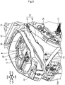
- Fig. 3 is an enlarged perspective view of a part of the electric motorcycle 1 with the seat 23 and the under-seat cowl 24 removed.
- the battery case 40 made from a hard resin or the like includes a lower case 42 having a bottomed box shape, and an upper case 41 engaged with an upper portion of the lower case 42.
- a hinge mechanism 44 for pivotally supporting the front end portion of the seat 23 in a swingable manner is provided.
- a hook opening 43 for allowing a hook to be engaged with a seat catch mechanism for locking the seat 23 in a closed state is provided.
- the two batteries B are stored side by side in the vehicle width direction, and an operation lever 60 (dot hatched area), which is gripped and operated by a rider is disposed at a position between the left and right batteries B. Below the operation lever 60, pressing holders 45 that are in contact with the upper surfaces of the batteries B are disposed.
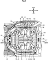
- Fig. 4 is a plan view of the battery case 40.
- Fig. 5 is a perspective view of the battery case 40 in a state where the battery B on the left side in the vehicle width direction is detached.
- Fig. 5 illustrates the battery case 40 viewed from the upper rear side of the left side of the vehicle body.
- the left and right batteries B arranged side by side in the vehicle width direction have the same shape and structure.
- a first side surface 104, which faces outside in the vehicle width direction, of each of the batteries B is formed from a curved plane that is convex outward in the vehicle width direction, whereas a second side surface 103 facing inside in the vehicle width direction, a third side surface 105 and the fourth side surface 106 facing the front side and the rear side of the vehicle body are formed as flat planes.
- a first grip 100 extending in the vehicle width direction and a second grip 101 that is formed continuously from the first grip 100 and extends in the longitudinal direction of the vehicle body are formed at the upper end portion of the battery B.
- An upper surface 102 of the battery B located below the first grip 100 and the second grip 101 has a conical concave shape to increase the distance between the upper surface 102 and the grips 100 and 101, which facilitates gripping of the grips 100 and 101.
- the operation lever 60 is disposed between the left and right batteries B and at the center in the vehicle width direction.
- the pressing holders 45 for pressing the upper surfaces 102 of the batteries B are provided on the front side and the rear side of each of the batteries B, and thus the number of provided pressing holders 45 is four as a total.
- the pressing holders 45 are pivotally supported at an upper part of the upper case 41 in a swingable manner, and are configured to press the upper surfaces 102 of the batteries B when the operation lever 60 is pushed downward.
- a grip portion 61 that extends in the longitudinal direction of the vehicle body and that is gripped by a rider is provided at an upper end portion of the operation lever 60, and a partition portion 62 inserted between the left and right batteries B is formed below the grip portion 61.
- pressing portions 64 extending in the vehicle width direction are formed at front and rear end portions of the grip portion 61.
- positioning plates 63 positioned below the pressing portions 64 are formed at front and rear end portions of the partition portion 62.
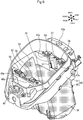
- Fig. 6 is a perspective view of the battery case 40.
- a link mechanism L which operates in association with a vertical sliding motion of the operation lever 60 and which makes/breaks the electrical connection between the batteries B and the vehicle body side.
- a pair of left and right terminal covers 42a for covering the connection portions of the terminals is provided.
- a pedestal 46 At an upper front end portion of the upper case 41, a pedestal 46, to which the hinge mechanism 44 is attached, is disposed.
- Fig. 7 is a perspective view of the upper case 41 as viewed from the upper front side of the vehicle body.
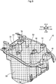
- Fig. 8 is a perspective view of the lower case 42 as viewed from the upper front side of the right side of the vehicle body, and
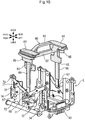
- Fig. 9 is a perspective view of the battery case 40 with the operation lever 60 removed.
- the battery case 40 is formed by combining the upper case 41 and the lower case 42 (dot hatched area), and the upper case 41 has a central opening 50 through which the batteries B pass.
- Support portions 56 and 58 for pivotally supporting the pressing holders 45 in a swingable manner are formed on the lower case 42, and are exposed above the vehicle body through rectangular openings 47 and 48 formed in the upper case 41 when the upper and lower cases 41 and 42 are engaged with each other.
- the pedestal 46, to which the hinge mechanism 44 is attached is also formed on the lower case 42, and is exposed above the vehicle body through a rectangular opening 53 formed in the upper case 41.
- the hook opening 43 allowing an access to the seat catch mechanism is formed in a rear end portion of the upper case 41.
- the opening 47 and the opening 48 are surrounded by ribs 47a and 48a standing upward of the vehicle body.
- positioning recesses 52 in which the positioning plates 63 of the operation lever 60 are placed are formed.
- Tapered surfaces 51 which are the outer side surfaces of the positioning recesses 52 in the vehicle width direction, have a tapered shape that is narrower toward the lower side.
- the main body portion 55 of the lower case 42 forms a bottomed recess 59 for storing the batteries B.
- a leg opening 57 into which a leg portion 66 (see Fig. 10 ) of the operation lever 60 is inserted, is formed between the support portions 56, which pivotally support the pressing holder 45.
- Another leg opening 57 is formed between the support portions 58 on the front side in the longitudinal direction of the vehicle body.
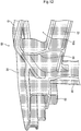
- Fig. 10 is a perspective view illustrating the structure of the operation lever 60 and the link mechanism L. Similar to the operation lever 60 having a substantially symmetrical shape in the longitudinal direction of the vehicle body and the vehicle width direction, the link mechanism L also has a substantially symmetrical shape in the longitudinal direction of the vehicle body and the vehicle width direction.
- a pair of left and right arm members 70 is pivotally supported in a swingable manner by first swing shafts 71 at upper end portions of long substrates 73 supporting the link mechanism L.
- first swing shafts 71 On one end sides of the arm members 70 which are positioned on the inner sides in the vehicle width direction, lower end portions 67 of the operation lever 60 are pivotally supported in a swingable manner by second swing shafts 68.
- the pivotally support portions of the second swing shafts 68 have an elongated hole shape for allowing slide of the leg portions 66 of the operation lever 60 in a substantially vertical direction.
- terminal holders 74 for supporting case-side terminals 90 are pivotally supported in a swingable manner.
- the terminal holders 74 are formed in a substantially U-shape surrounding side surfaces of the batteries B facing in the longitudinal direction of the vehicle body.
- the link mechanism L having the configuration of "lever” including the fulcrum, the point of effort, and the point of load. More specifically, it is possible to obtain the link mechanism L, in which the first swing shafts 71 work as fulcrums, the second swing shafts 68 work as points of effort, and third swing shafts 72 work as points of load to cause the terminal holders 74 to be raised when the operation lever 60 is pushed down, and cause the terminal holders 74 to be lowered when the operation lever 60 is pulled up. In addition, since the two terminal holders 74 are connected to the link mechanism L, it is possible to obtain a structure causing the two terminal holders 74 to move vertically with the single operation lever 60. Further, the terminal holders 74 can be moved vertically with a small force using the principle of leverage.
- the arm members 70 and the substrates 73 can be made from a thin plate metal.
- Fig. 11 is a perspective view of the operation lever 60.
- the lower end portions 67 connected to one end portions of the arm members 70 are made from a thin plate metal, and the upper portion including the grip portion 61 and the partition portion 62 is made from a hard synthetic resin or the like to reduce the weight.
- the lower end portions 67 are insert-molded in the leg portions 66 deeply in the longitudinal direction to enhance the strength of the leg portions 66.
- a grip opening 60a Between the grip portion 61 and the partition portion 62, a grip opening 60a, through which a rider puts his/her fingers, is formed.
- the left and right side surfaces of the connecting portions 69 in the vehicle width direction have a tapered shape that is narrower toward the lower side.
- the positioning plates 63 extending in the vehicle width direction between the leg portions 66 and the partition portion 62 each include side end surfaces 63a that come in contact with the tapered surfaces 51, which are tapered side surfaces of the positioning recesses 52, and upper end surfaces 63b that come in contact with the lower portions of the pressing holders 45 and push up the pressing holders 45 when the operation lever 60 is pulled upward.
- chamfered portions 63c are formed at corner portions on the lower sides of the positioning plates 63 having substantially a rectangular shape when viewed from the front.
- stopper members 65 standing downward are formed on the lower portions of the pressing portions 64.
- the side end surfaces 63a of the positioning plates 63 inserted into the positioning recesses 52 have a tapered shape that is narrower toward the lower side.
- the positioning plates 63 are placed in the positioning recesses 52 having the tapered surfaces 51 functioning as guides, enabling the operation lever 60 to be smoothly held at the neutral position by simply pushing down the operation lever 60.
- the chamfered portions 63c are formed at the corner portions on the lower sides of the positioning plates 63, when the operation lever 60 is being pushed down, the chamfered portions 63c come into contact with the tapered surfaces 51 of the positioning recesses 52 so that the operation of pushing down the operation lever 60 can be performed more smoothly.
- Fig. 12 is a partially enlarged view of Fig. 11 .
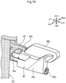
- Fig. 13 is an enlarged perspective view illustrating a configuration around the stopper members 65.
- both side surfaces of the connecting portions 69 in the vehicle width direction have a tapered shape that is narrower toward the lower side.
- the operation lever 60 is smoothly retracted due to the tapered shape of the connecting portions 69, making it easy to pull out the batteries B.
- the stopper members 65 provided at the lower portions of the pressing portions 64 are in contact with a ceiling surface of the upper case 41 positioned between the pressing holders 45 on the left and right sides in the vehicle width direction to define the lowermost position of the operation lever 60.
- the stopper members 65 each are formed to have a substantially rectangular parallelepiped shape that has three hollow recesses and extends in the vehicle width direction.
- Fig. 14 is a perspective view illustrating a cross section taken along line XIV-XIV of Fig. 4 .
- the two batteries B are arranged side by side in the vehicle width direction.
- the operation lever 60 includes the grip portion 61 projecting upward from the upper surfaces 102 of the batteries B in a state where the batteries B are stored in the battery case 40, and the partition portion 62 inserted between the batteries B in the state where the batteries B are stored in the battery case 40.
- the partition portion 62 is formed narrower than the grip portion 61, and the grip opening 60a through which a rider puts his/her fingers is formed between the grip portion 61 and the partition portion 62.
- the partition portion 62 prevents the batteries B from interfering with each other to protect the batteries B from an impact, and the heat radiation effect of the batteries B can be enhanced. Further, by putting fingers through the grip opening 60a, the wide grip portion 61 can be easily gripped, and the operation of attaching and detaching the batteries B can be facilitated.
- the partition portion 62 may be further extended downward to enhance the insulation function between the batteries B.
- Figs. 15 and 16 are front views illustrating the structure of the link mechanism L.
- Fig. 15 illustrates a state where the operation lever 60 is pulled up
- Fig. 16 illustrates a state where the operation lever 60 is pushed down to a predetermined lowermost position.
- the pressing holders 45 pivotally supported in a swingable manner by the battery case 40 are urged by an elastic member in a direction to press the upper surfaces of the batteries B.
- the operation lever 60 is pulled upward, the upper end surface 63b of the positioning plate 63 comes into contact with the lower surfaces of the pressing holders 45, and when the operation lever 60 is pulled upward further against the urging force of the elastic member, the pressing holders 45 are swung upward to stand.
- the terminal holders 74 connected to the link mechanism L are lowered to a retracted position D, and the case-side terminals 90 are separated from the batteries B.
- the batteries B can be held in a manner being sandwiched from the upper and lower sides.
- the batteries B can be stably held, and good electrical connection can be maintained even when, for example, the vehicle rides over a large level difference.
- the grip portion 61 positioned above the batteries B is gripped and the operation lever 60 is pushed down, the two batteries B are held at the same time, and when the operation lever 60 is pulled up, the batteries B can be in a detachable state, so that the convenience of the attaching and detaching operation of the batteries B is enhanced.
- the operation lever 60 is configured to be swingable about the second swing shafts 68 in a state where the operation lever 60 is pulled upward to move the terminal holders 74 to the retracted position D.
- two batteries B are arranged side by side in the vehicle width direction, and the first swing shafts 71, the second swing shafts 68, and the third swing shafts 72 are disposed at positions where they overlap with the batteries B in the front view of the vehicle body.
- the link mechanism L by disposing the link mechanism L at a position where it overlaps with the batteries B when viewed from the front of the vehicle body, it is possible to reduce the size of the battery case 40 and the vehicle body.
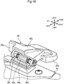
- Fig. 17 is a perspective view illustrating one of the pressing holders 45 in a state where the operation lever 60 is pushed down to the predetermined lowermost position.
- Figs. 18 and 19 are perspective views of the pressing holder 45 on the rear side of the vehicle body, viewed from the rear side of the vehicle body.
- Fig. 18 illustrates a state where the pressing holder 45 presses the upper surface 102 of the battery B
- Fig. 19 illustrates a state where the pressing holder 45 stands upward along with the pulling up operation of the operation lever 60.
- the pressing holder 45 includes a main body portion 45c pivotally supported in a swingable manner by a swing shaft 45a, an elastic member 45d urging the main body portion 45c in a direction of pressing the upper surface 102 of the battery B, and a pressing portion 45b that is fixed to the main body portion 45c and is in contact with the upper surface 102 of the battery B.
- the main body portion 45c is made from a metal such as aluminum or a hard synthetic resin, and the pressing portion 45b can be made from a resin such as rubber.
- an interference portion 45e having a bottomed box shape is provided, and to the interference portion 45e, the upper end surface 63b of the positioning plate 63 comes into contact from a lower position.
- the elastic member 45d is a coil spring wound around the swing shaft 45a, and can apply an urging force in one direction to the swing motion of the pressing holder 45 with a simple structure.
- Fig. 20 is a left side view illustrating the pressing holder 45 in a state where the operation lever 60 is pushed down to the predetermined lowermost position.
- the interference portion 45e has a shape such that the interference portion 45e projects downward from the pressing holder 45 at a frontward (rearward) position of the swing shaft 45a in the longitudinal direction of the vehicle body in the state where the operation lever 60 is pushed down.
- the pressing portion 45b is disposed outside the interference portion 45e in the vehicle width direction and in front of the interference portion 45e in the longitudinal direction of the vehicle body.
- Fig. 21 is a cross-sectional view taken along line XXI-XXI of Fig. 4 .
- the batteries B are not illustrated for the sake of description.
- the swing shaft 45a of the pressing holder 45 is provided to extend in the vehicle width direction while the operation lever 60 slides in the vertical direction.
- the pressing holder 45 can be easily swung in association with the sliding motion of the operation lever 60.
- the two corner portions 61a on the upper end side of the grip portion 61 are formed as curved planes, when the batteries B are inserted into the battery case 40, the batteries B can be protected even if the side surfaces of the batteries B come into contact with the operation lever 60.
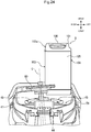
- Fig. 22 is a cross-sectional view taken along line XXII-XXII of Fig. 21 .
- Fig. 23 is a cross-sectional view taken along line XXIII-XXIII of Fig. 21 .
- the pressing holder 45 is provided with a contact portion 49 that comes into contact with the operation lever 60 when the operation lever 60 is pushed down.
- the contact portion 49 includes a first contact portion 49a (see Fig. 22 ) which is not located at a position radially outer than the swing shaft 45a, and a second contact portion 49b (see Fig. 23 ) which is located radially outer than and close to the swing shaft 45a.
- the area of a portion where the first contact portion 49a provided at a position near to the center in the vehicle width direction and the operation lever 60 are in contact with each other is set to be larger than the area of a portion where the second contact portion 49b provided at a position near to the outer side in the vehicle width direction and the operation lever 60 are in contact with each other.
- the contact portion 49 it is possible to obtain a configuration in which the pressing holders 45 press the upper surfaces 102 of the batteries B and the operation lever 60 comes into contact with the pressing holders 45 by storing the batteries B in the battery case 40 and pressing down the operation lever 60. That is, the swing motion of the pressing holders 45 is limited by the operation lever 60, so that the batteries B are prevented from moving upward of the vehicle body even when, for example, the vehicle rides over a large level difference, thereby maintaining a good electrical connection.
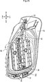
- Fig. 24 is a front view illustrating the relationship between one of the batteries B and the operation lever 60 during storage of the battery B.
- the battery B has a substantially rectangular parallelepiped shape elongated in the vertical direction of the vehicle body.
- the operation lever 60 is configured such that when the battery B is pulled upward from a state where the terminal holder 74 is in the retracted position D, the operation lever 60 is pushed away by an inclined side surface 103a provided at a position near to an upper portion of the battery B, and thus is swung in a direction away from the battery B. That is, when the battery B is pulled upward, the operation lever 60 automatically swings to a state where the battery B can be detached, facilitating the operation of detaching the battery B.
- the inclination of the center line C of the operation lever 60 is set such that even when the battery B on a side toward which the operation lever 60 is inclined is pulled out, the inclined side surface 103a moves along the shape of the connecting portion 69 of the operation lever 60 and the operation lever 60 can automatically swing to the opposite side.
- the upper corner portions of the grip portion 61 of the operation lever 60 function as guide members for placing the batteries into predetermined positions by making the inner side surfaces, in the vehicle width direction, of the batteries B come into contact with the upper corner portions when the batteries B are inserted.
- Fig. 25 is a perspective view of a seat bottom plate 80 forming the bottom portion of the seat 23 as viewed from a lower position of the vehicle body.
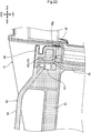
- Fig. 26 is a cross-sectional view taken along line XXVI-XXVI of Fig. 4 .
- the seat 23 and the seat bottom plate 80 are also illustrated.
- a fixing member 82 for fixing the seat 23 to the hinge mechanism 44 is provided, while at a rear end portion of the seat bottom plate 80, a pair of left and right vibrationproof rubber portions 84a for absorbing impact and vibrations when the seat 23 is closed and a hook 83 for engaging with a seat catch mechanism 110 are provided.
- bosses 84 that come into contact with the upper surface of the operation lever 60 are provided.
- the bosses 84 can be formed from a hard synthetic resin or the like.
- a recess 85 is formed around the boss 84 on the front side in the longitudinal direction of the vehicle body to avoid interference with the pressing portion 64 of the operation lever 60.
- the bosses 84 are configured to have a function of pushing down the operation lever 60 when the seat 23 is closed in a state where the operation lever 60 is above a predetermined lowermost position, but not to be in contact with the operation lever 60 in a state where the operation lever 60 is pushed down to the predetermined lowermost position.
- the bosses 84 are configured such that when the seat 23 is closed, if the operation lever 60 is not pushed down sufficiently, the bosses 84 come into contact with the operation lever 60 to push the operation lever 60 down at least to a position where the battery-side terminals 75 and the case-side terminals 90 are electrically connected, and if the operation lever 60 is pushed down to the predetermined lowest position, the bosses 84 are not in contact with the operation lever 60, whereby the operation lever 60 sufficiently pushed down to the predetermined lowermost position can be prevented from being further applied with a load.
- Fig. 27 is an explanatory view of a structure of one of the battery-side terminals 75.
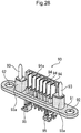
- Fig. 28 is a perspective view of one of the case-side terminals 90.
- the battery-side terminal 75 is embedded in a lower surface 107 of the battery B at a position near to the outer side in the vehicle width direction.
- slits 76 and engaging holes 77 are formed in the battery-side terminal 75.
- seven terminal plates 94 of the case-side terminal 90 are inserted, and into the engaging holes 77, positioning pins 93 supported by support portions 93a at positions outer than the terminal plates 94 are inserted.
- through holes 92 are formed in a base plate 91 supporting the terminal plates 94 and the positioning pins 93 of the case-side terminal 90.
- through holes 92 Through the through holes 92, support shafts (see Figs 29 and 30 ) that enable the case-side terminal 90 to slide with respect to the terminal holder 74 pass.
- Protection plates 94a for protecting the terminal plates 94 are provided to stand on the side of the terminal plates 94, and harness holders 95 for supporting harnesses for supplying electric power are provided on the lower surface of the base plate 91.
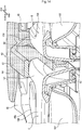
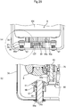
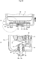
- Figs. 29 and 30 are explanatory views of a structure of a preload mechanism for pressing the case-side terminal 90 against the battery-side terminal 75.
- Fig. 29 illustrates a state where the operation lever 60 is pushed down to a position where the case-side terminal 90 is engaged with the battery-side terminal 75
- Fig. 30 illustrates a state where the operation lever 60 is further pushed down to the predetermined lowermost position to apply a preload.
- parts (b) are enlarged cross-sectional views of parts (a) in the dashed circles.
- the case-side terminal 90 is supported slidably in the vertical direction with respect to the terminal holder 74 by cylindrical support shafts 98 passing through through-holes 74a formed in the terminal holder 74.
- Coil springs 97 wound around the support shafts 98 are configured to generate an elastic force in a direction of separating the terminal holder 74 and the case-side terminals 90 from each other.
- the longest distance between the terminal holder 74 and the case-side terminal 90 is limited by snap rings 98a, while the shortest distance between the terminal holder 74 and the case-side terminal 90 is limited by cup members 96 that are disposed on the lower surface of the base plate 91 and that covers the coil springs 97.
- the electrical connection between the case-side terminal 90 and the battery-side terminal 75 is completed before the operation lever 60 reaches the lowermost position of the operation lever 60, and when the operation lever 60 is further pushed down to the lowermost position, the coil spring 97 is contracted to generate the preload. Even in this case, a gap 99 is ensured between the cup members 96 and the terminal holders 74.
- the preload mechanism enables generation of a pressing force for pressing the case-side terminal 90 against the battery-side terminal 75 in a state where the case-side terminal 90 is moved to the connected position by disposing the springs 97 between the case-side terminal 90 and the terminal holder 74 for urging the case-side terminal 90 in a direction to press the battery-side terminal 75.
- the electrical connection can be maintained by causing the case-side terminal 90 to follow the movement of the batteries B.
- the single operation lever 60 that limits the vertical movement of the batteries B when the operation lever 60 is pushed downward in a state where the batteries B are stored in the battery case 40 and the link mechanism L for connecting the operation lever 60 and the terminal holders 74, the vertical movement of the batteries B can be limited by the single operation lever 60, and the attaching and detaching operation of the batteries B is facilitated. Also, since the link mechanism L including a plurality of swing shafts, even when an ineffective stroke occurs in the motion of the operation lever 60, the coil springs 97 absorb the ineffective stroke after the case-side terminals 90 and the battery-side terminals 75 come into contact with each other, so that preloading can be effectively applied to both terminals.
- the support shafts 98, around which the coil springs 97 are wound are provided as a pair with the case-side terminals 90 interposed therebetween, when sliding mechanisms of the terminal holder 74 are provided on both sides of the case-side terminal 90, the inclination of the case-side terminal 90 is prevented and a smooth sliding motion is enabled. As a result, good electrical connection can be maintained between the case-side terminals 90 and the battery-side terminals 75.
- the shape and structure of the batteries, the number and mounting position of the batteries, the shape and structure of the battery case and the operation lever, the shape and structure of the pressing holders and the terminal holders, the shape and structure of the link mechanism and the preload mechanism, and the like are not limited to those described in the above-described embodiment, and various modifications are possible.
- the battery attaching/detaching structure for the saddle-type vehicle according to the present invention can be applied to saddle-type three-wheel electric vehicles, four-wheel electric vehicles, and the like.
Landscapes
- Engineering & Computer Science (AREA)
- Mechanical Engineering (AREA)
- Chemical & Material Sciences (AREA)
- Chemical Kinetics & Catalysis (AREA)
- Electrochemistry (AREA)
- General Chemical & Material Sciences (AREA)
- Transportation (AREA)
- Power Engineering (AREA)
- Life Sciences & Earth Sciences (AREA)
- Sustainable Development (AREA)
- Sustainable Energy (AREA)
- Aviation & Aerospace Engineering (AREA)
- Combustion & Propulsion (AREA)
- Manufacturing & Machinery (AREA)
- Battery Mounting, Suspending (AREA)
- Arrangement Or Mounting Of Propulsion Units For Vehicles (AREA)
- Automatic Cycles, And Cycles In General (AREA)
Abstract
Description
- The present invention relates to a battery attaching/detaching structure for a saddle-type vehicle, and more particularly to a battery attaching/detaching structure for a saddle-type vehicle applicable to a portable battery detachably stored in a body of the saddle-type electric vehicle and a battery storage portion.
- In recent years, a saddle-type electric vehicle that travels by driving a motor with electric power supplied from an on-board battery has been developed. In such a saddle-type electric vehicle, a configuration in which a portable battery detachable from a vehicle body is used to facilitate charging, maintenance, and the like is also well known.
-
Patent Literature 1 discloses a configuration of a scooter-type electric vehicle having a low floor between a steering handle and a seat, in which two batteries are stored below an openable/closable seat. In this configuration, the two batteries having a substantially rectangular parallelepiped shape elongated in the vertical direction of the vehicle body are stored in two storing recesses arranged adjacent to each other in the longitudinal direction of the vehicle body, and when the batteries are stored in predetermined positions, the connection terminals on the battery side and the connection terminals on the vehicle body side are engaged with each other. - Patent Literature 1:
WO 2012/043518 A1 - Here, in the configuration in which connection terminals are engaged by storing batteries in storing recesses as in
Patent Literature 1, it is preferable to provide a mechanism for holding the stored batteries at predetermined positions so that the batteries do not move in the upward direction of the vehicle body and then do not affect the electrical connection when, for example, the vehicle rides over a large level difference. In this regard, there has been a demand for a configuration capable of maintaining a good electrical connection while holding batteries in predetermined positions by a holding mechanism. - It is an object of the present invention to solve the problems of the above-described prior art and provide a battery attaching/detaching structure for a saddle-type vehicle capable of limiting the movement of a stored battery and of maintaining good electrical connection between a battery-side terminal and a case-side terminal.
- In order to achieve the above-described object, the present invention has a first feature in that a battery attaching/detaching structure for a saddle-type vehicle, including a plurality of substantially rectangular parallelepiped batteries (B) for supplying electric power to a power source of the saddle-type vehicle (1); a battery case (40) in which the batteries (B) are stored; battery-side terminals (75) provided on lower surfaces (107) of the batteries (B); and case-side terminals (90) engaged with the battery-side terminals (75), comprises terminal holders (74) that support the case-side terminals (90) such that the case-side terminals (90) are movable between a connected position (U) where the case-side terminals (90) are connected to the battery-side terminals (75) and a retracted position (D) where the case-side terminals (90) are separated from the battery-side terminals (75), wherein between the case-side terminals (90) and the terminal holders (74), springs (97) for urging the case-side terminals (90) in a direction of pressing the battery-side terminals (75) are disposed.
- The present invention has a second feature in that the battery attaching/detaching structure for a saddle-type vehicle further includes: a single operation lever (60) that, when pushed downward in a state where the batteries (B) are stored in the battery case (40), limits vertical movement of the batteries (B); and a link mechanism (L) that connects the operation lever (60) and the terminal holders (74).
- The present invention has a third feature in that the operation lever (60) is configured to be vertically slidable along a longitudinal direction of the batteries (B), and the battery attaching/detaching structure for a saddle-type vehicle further includes a pressing holder (45) that is swingable and presses upper surfaces (102) of the batteries (60) when the operation lever (60) is moved to a lowermost position.
- The present invention has a fourth feature in that the battery case (40) is disposed below a seat (23) that is openable/closable and that is provided in the saddle-type vehicle (1), and a boss (84) positioned above the operation lever (60) is provided on a bottom surface of the seat (23).
- The present invention has a fifth feature in that the boss (84) is not in contact with the operation lever (60) in a state where the operation lever (60) is pushed down to a predetermined lowermost position.
- The present invention has a sixth feature in that the terminal holders (74) are plate members that are substantially U-shaped and cover lower portions of the case-side terminals (90), the terminal holders (74) and the case-side terminals (90) are configured to be slidable in a vertical direction when support shafts (98) that are cylindrical and extend downward from lower surfaces of the terminal holders (74) are inserted into through holes (74a) formed in the terminal holders (74)" and the springs (97) are coil springs wound around the support shafts (98).
- The present invention has a seventh feature in that the support shafts (98), around which the springs (97) are wound, are provided as pairs each with a corresponding one of the case-side terminals (90) interposed therebetween.
- The present invention has an eighth feature in that the number of the batteries (B) is two and the batteries (B) are arranged side by side, and the battery attaching/detaching structure for a saddle-type vehicle further includes: a single operation lever (60) that, when pushed downward in a state where the batteries (B) are stored in the battery case (40), limits vertical movement of the batteries (B); and the terminal holders (74) provided for the two respective batteries (60) are connected to the operation lever (60).
- According to the first feature, the battery attaching/detaching structure for a saddle-type vehicle, including a plurality of substantially rectangular parallelepiped batteries (B) for supplying electric power to a power source of the saddle-type vehicle (1); a battery case (40) in which the batteries (B) are stored; battery-side terminals (75) provided on lower surfaces (107) of the batteries (B); and case-side terminals (90) engaged with the battery-side terminals (75), comprises terminal holders (74) that support the case-side terminals (90) such that the case-side terminals (90) are movable between a connected position (U) where the case-side terminals (90) are connected to the battery-side terminals (75) and a retracted position (D) where the case-side terminals (90) are separated from the battery-side terminals (75), wherein between the case-side terminals (90) and the terminal holders (74), springs (97) for urging the case-side terminals (90) in a direction of pressing the battery-side terminals (75) are disposed. Thus, it is possible to generate a pressing force for pressing the case-side terminals against the battery-side terminals in a state where the case-side terminals are moved to the connected position. As a result, even when the batteries move in the upward direction of the vehicle body when, for example, the vehicle rides over a large level difference, the electrical connection can be maintained by causing the case-side terminals to follow the movement of the batteries.
- According to the second feature, the battery attaching/detaching structure for a saddle-type vehicle further includes: a single operation lever (60) that, when pushed downward in a state where the batteries (B) are stored in the battery case (40), limits vertical movement of the batteries (B); and a link mechanism (L) that connects the operation lever (60) and the terminal holders (74). Thus, the vertical movement of the batteries can be limited by the single operation lever, and the attaching and detaching operation of the batteries is facilitated. In addition, since the link mechanism includes a plurality of rotation shafts, even when an ineffective stroke occurs in the motion of the operation lever, the springs absorb the ineffective stroke after the case-side terminals and the battery-side terminals come into contact with each other, so that preloading can be effectively applied to both terminals.
- According to the third feature, the operation lever (60) is configured to be vertically slidable along a longitudinal direction of the batteries (B), and the battery attaching/detaching structure for a saddle-type vehicle further includes a pressing holder (45) that is swingable and presses upper surfaces (102) of the batteries (60) when the operation lever (60) is moved to a lowermost position. Thus, by pushing the operation lever down, the case-side terminals are pressed against the battery-side terminal by the urging force of the springs, and also the upper surfaces of the batteries are pressed by the pressing holder, facilitating maintenance of electrical connection between the terminals.
- According to the fourth feature, the battery case (40) is disposed below a seat (23) that is openable/closable and that is provided in the saddle-type vehicle (1), and a boss (84) positioned above the operation lever (60) is provided on a bottom surface of the seat (23). Thus, when the seat is closed in a state where the operation lever is above a predetermined lowermost position, the operation lever can be pushed down by the boss.
- According to the fifth feature, the boss (84) is not in contact with the operation lever (60) in a state where the operation lever (60) is pushed down to the predetermined lowermost position. Thus, when the seat is closed, if the operation lever is not pushed down sufficiently, the boss comes into contact with the operation lever to push the operation lever down at least to an allowable position, and if the operation lever is pushed down to the predetermined lowest position, the boss is not in contact with the operation lever, whereby the operation lever sufficiently pushed down to the predetermined lowermost position can be prevented from being further applied with a load.
- According to the sixth feature, the terminal holders (74) are plate members that are substantially U-shaped and cover lower portions of the case-side terminals (90), the terminal holders (74) and the case-side terminals (90) are configured to be slidable in a vertical direction when support shafts (98) that are cylindrical and extend downward from lower surfaces of the terminal holders (74) are inserted into through holes (74a) formed in the terminal holders (74)" and the springs (97) are coil springs wound around the support shafts (98). Thus, the case-side terminals can be urged to the battery side with a simple configuration.
- According to the seventh feature, the support shafts (98), around which the springs (97) are wound, are provided as pairs each with a corresponding one of the case-side terminals (90) interposed therebetween. Thus, when sliding mechanisms of the terminal holder are provided on both sides of each of the case-side terminal, the inclination of the case-side terminals is prevented and a smooth sliding motion is enabled. As a result, good electrical connection can be maintained between the case-side terminals and the battery-side terminals.
- According to the eighth feature, the number of the batteries (B) is two and the batteries (B) are arranged side by side, and the battery attaching/detaching structure for a saddle-type vehicle further includes: a single operation lever (60) that, when pushed downward in a state where the batteries (B) are stored in the battery case (40), limits vertical movement of the batteries (B); and the terminal holders (74) provided for the two respective batteries (60) are connected to the operation lever (60). The tolerance may become large because the terminal holders are provided for the two respective batteries, but since the springs are provided between the case-side terminals and the terminal holders, it is easy to set an arbitrary stroke amount according to an assumed tolerance.
-
-
Fig. 1 is a left side view of an electric motorcycle as a saddle-type electric vehicle according to an embodiment of the present invention. -
Fig. 2 is a left side view of the electric motorcycle with main exterior components removed. -
Fig. 3 is an enlarged perspective view of a part of the electric motorcycle with a seat and an under-seat cowl removed. -
Fig. 4 is a plan view of a battery case. -
Fig. 5 is a perspective view of the battery case in a state where a battery on the left side in the vehicle width direction is detached. -
Fig. 6 is a perspective view of the battery case. -
Fig. 7 is a perspective view of an upper case as viewed from the upper front side of the vehicle body. -
Fig. 8 is a perspective view of a lower case as viewed from the upper front side of the right side of the vehicle body. -
Fig. 9 is a perspective view of the battery case with an operation lever removed. -
Fig. 10 is a perspective view illustrating the structure of the operation lever and a link mechanism. -
Fig. 11 is a perspective view of the operation lever. -
Fig. 12 is a partially enlarged view ofFig. 11 . -
Fig. 13 is an enlarged perspective view illustrating a configuration around a stopper member. -
Fig. 14 is a perspective view illustrating a cross section taken along line XIV-XIV ofFig. 4 . -
Fig. 15 is a front view illustrating the structure of the link mechanism (a state where the operation lever is pulled up). -
Fig. 16 is a front view illustrating the structure of the link mechanism (a state where the operation lever is pushed down to a predetermined lowermost position). -
Fig. 17 is a perspective view illustrating a pressing holder in a state where the operation lever is pushed down to the predetermined lowermost position. -
Fig. 18 is a perspective view of the pressing holder, which is on the rear side of the vehicle body, viewed from the rear side of the vehicle body (a state where the upper surface of the battery is pressed). -
Fig. 19 is a perspective view of the pressing holder, which is on the rear side of vehicle body, viewed from the rear side of the vehicle body (a state where the pressing holder stands upward along with the pulling up operation of the operation lever). -
Fig. 20 is a left side view illustrating the pressing holder in a state where the operation lever is pushed down to the predetermined lowermost position. -
Fig. 21 is a cross-sectional view taken along line XXI-XXI ofFig. 4 . -
Fig. 22 is a cross-sectional view taken along line XXII-XXII ofFig. 21 . -
Fig. 23 is a cross-sectional view taken along line XXIII-XXIII ofFig. 21 . -
Fig. 24 is a front view illustrating the relationship between a battery and the operation lever during storage of the battery. -
Fig. 25 is a perspective view of a seat bottom plate as viewed from the lower side of the vehicle body. -
Fig. 26 is a cross-sectional view taken along line XXVI-XXVI ofFig. 4 . -
Fig. 27 is an explanatory view of the structure of a battery-side terminal. -
Fig. 28 is a perspective view of a case-side terminal. -
Fig. 29 is an explanatory view of a structure of a preload mechanism for pressing the case-side terminal against the battery-side terminal (a state where the operation lever is pressed down to some extent). -
Fig. 30 is an explanatory view of a structure of a preload mechanism for pressing the case-side terminal against the battery-side terminal (a state where the operation lever is pressed down to the predetermined lowermost position). - Hereinafter, a preferred embodiment of the present invention will be described in detail with reference to the drawings.
Fig. 1 is a left side view of anelectric motorcycle 1 as a saddle-type electric vehicle according to an embodiment of the present invention. Theelectric motorcycle 1 is a so-called scooter-type electric vehicle provided with alow floor 25, on which a rider places his or her feet, between asteering handle 2 and aseat 23. - A pair of left and right
front forks 9 in the vehicle width direction for pivotally supporting a front wheel WF in a rotatable manner is configured to be swingable by asteering handle 2 extending in the vehicle width direction. Arearview mirror 3 and awindshield screen 4 are attached to ahandle cover 33 covering the front and rear of thesteering handle 2. Below thehandle cover 33, afront cover 5 covering the front side of a front side part of the vehicle body and afloor panel 27 covering the rear side of the front side part of the vehicle body and facing legs of a rider are disposed. In front of thefront cover 5, a headlight 7 supported by alight stay 31 and a pair of left and rightfront blinker devices 6 is disposed. Afront fender 8 covering the upper portion of the front wheel WF is supported between the left and rightfront forks 9. - A
brake pedal 26 for operating the brake of a rear wheel WR is disposed on the upper surface of thelow floor 25, and an undercover 10 connected to the lower end portion of thefront cover 5 is disposed below thelow floor 25. Below theseat 23 on which a driver sits, an under-seat cowl 24 having a curved shape that is convex toward the front of the vehicle body is disposed. In the under-seat cowl 24, a pair of left andright slits 22 for proactively taking in the traveling wind from the front side of the vehicle body is formed. - Below the under-
seat cowl 24, aside stand 11 and atandem step 13 are disposed. At a position rearward of the under-seat cowl 24, a pair ofrear cowls 21 in the vehicle width direction is disposed, and above therear cowl 21, aluggage carrier 37 surrounded by agrip pipe 36 and arear carrier 20 attached to the upper surface of theluggage carrier 37 are disposed. At a position rearward of therear cowl 21, atail light 19 andrear blinker devices 28 are disposed. - At a position rearward of the
under cover 10, a swing unit-type power unit P which pivotally supports the rear wheel WR in a rotatable manner with an axle S and incorporates a motor M for driving the rear wheel WR is attached to the vehicle body frame in a swingable manner via alink mechanism 12. A rear portion of the power unit P is suspended from the vehicle body frame by arear cushion 18, and arear fender 17 for covering an upper portion of the rear wheel WR is attached to an upper portion of the power unit P. - A
cover member 38 for receiving traveling wind introduced through theslits 22 in the under-seat cowl 24 and the traveling wind flowing inside theunder cover 10 is disposed at a position between the under-seat cowl 24 and therear fender 17. -
Fig. 2 is a left side view of theelectric motorcycle 1 with main exterior components removed. The vehicle body frame F of theelectric motorcycle 1 includes a main frame F2 that extends downward of the vehicle body from a head pipe F1 and that is at the center in the vehicle width direction, a pair of left and right underframes F3 that are connected to the lower end portion of the main frame F2 and curve rearward of the vehicle body, rising portions F4 that rise upward of the vehicle body from the rear end portions of the underframes F3, and a pair of left and right rear frames F6 connected to the rising portions F4 and extending rearward of the vehicle body. To front portions of the rising portions F4, a curved pipe F5 connecting the left and right rising portions F4 is connected. - The head pipe F1 pivotally supports a
steering stem 34 in a rotatable manner. To an upper end portion of thesteering stem 34, the steering handle 2 is fixed, and to a lower end portion, on the other hand, of thesteering stem 34, abottom bridge 32 supporting upper end portions of thefront forks 9 is fixed. Below theseat 23, there is disposed abattery case 40 for storing two batteries (high voltage batteries) B for supply electric power to a motor M in a state where the batteries are arranged side by side in the vehicle width direction. The rated voltage of the batteries B is, for example, 48 V. Theseat 23 is pivotally supported by an upper front end portion of thebattery case 40 so as to be openable and closable, and functions as an openable/closable lid of thebattery case 40. - The
battery case 40 is stored in a space rearward of the curved pipe F5 and between the pair of left and right rising portions F4. The under-seat cowl 24 (seeFig. 1 ) extends from the front of the curved pipe F5 to the side of the left and right rising portions F4 so as to cover the front and side of thebattery case 40. Below thelow floor 25, astorage case 30 for storing a low voltage sub-battery B2 for supplying electric power to auxiliary devices such as the headlight 7 and electrical components such as a fuse are disposed. The rated voltage of the sub-battery B2 is, for example, 12 V. - The
cover member 38 for receiving traveling wind from the front of the vehicle body at the front of therear fender 17 is disposed on the rear surface side of thebattery case 40, and a power control unit (PCU) 39 for controlling the electric power supply to the motor M is disposed at a position near to an upper portion of the rear surface side of thebattery case 40. -
Fig. 3 is an enlarged perspective view of a part of theelectric motorcycle 1 with theseat 23 and the under-seat cowl 24 removed. This figure illustrates themotorcycle 1 viewed from the upper front side of the left side of the vehicle body. Thebattery case 40 made from a hard resin or the like includes alower case 42 having a bottomed box shape, and anupper case 41 engaged with an upper portion of thelower case 42. At the upper front end portion of theupper case 41, ahinge mechanism 44 for pivotally supporting the front end portion of theseat 23 in a swingable manner is provided. At the upper rear end portion of theupper case 41, ahook opening 43 for allowing a hook to be engaged with a seat catch mechanism for locking theseat 23 in a closed state is provided. - The two batteries B are stored side by side in the vehicle width direction, and an operation lever 60 (dot hatched area), which is gripped and operated by a rider is disposed at a position between the left and right batteries B. Below the
operation lever 60, pressingholders 45 that are in contact with the upper surfaces of the batteries B are disposed. -
Fig. 4 is a plan view of thebattery case 40.Fig. 5 is a perspective view of thebattery case 40 in a state where the battery B on the left side in the vehicle width direction is detached.Fig. 5 illustrates thebattery case 40 viewed from the upper rear side of the left side of the vehicle body. The left and right batteries B arranged side by side in the vehicle width direction have the same shape and structure. Afirst side surface 104, which faces outside in the vehicle width direction, of each of the batteries B is formed from a curved plane that is convex outward in the vehicle width direction, whereas asecond side surface 103 facing inside in the vehicle width direction, athird side surface 105 and thefourth side surface 106 facing the front side and the rear side of the vehicle body are formed as flat planes. - A
first grip 100 extending in the vehicle width direction and asecond grip 101 that is formed continuously from thefirst grip 100 and extends in the longitudinal direction of the vehicle body are formed at the upper end portion of the battery B. Anupper surface 102 of the battery B located below thefirst grip 100 and thesecond grip 101 has a conical concave shape to increase the distance between theupper surface 102 and thegrips grips - The
operation lever 60 is disposed between the left and right batteries B and at the center in the vehicle width direction. Thepressing holders 45 for pressing theupper surfaces 102 of the batteries B are provided on the front side and the rear side of each of the batteries B, and thus the number of providedpressing holders 45 is four as a total. Thepressing holders 45 are pivotally supported at an upper part of theupper case 41 in a swingable manner, and are configured to press theupper surfaces 102 of the batteries B when theoperation lever 60 is pushed downward. - Referring to
Fig. 5 , agrip portion 61 that extends in the longitudinal direction of the vehicle body and that is gripped by a rider is provided at an upper end portion of theoperation lever 60, and apartition portion 62 inserted between the left and right batteries B is formed below thegrip portion 61. In addition, pressingportions 64 extending in the vehicle width direction are formed at front and rear end portions of thegrip portion 61. Further,positioning plates 63 positioned below thepressing portions 64 are formed at front and rear end portions of thepartition portion 62. -
Fig. 6 is a perspective view of thebattery case 40. In front of thelower case 42 in the longitudinal direction of the vehicle body, there is disposed a link mechanism L which operates in association with a vertical sliding motion of theoperation lever 60 and which makes/breaks the electrical connection between the batteries B and the vehicle body side. At a lower end portion of thelower case 42, a pair of left and right terminal covers 42a for covering the connection portions of the terminals is provided. At an upper front end portion of theupper case 41, apedestal 46, to which thehinge mechanism 44 is attached, is disposed. -
Fig. 7 is a perspective view of theupper case 41 as viewed from the upper front side of the vehicle body.Fig. 8 is a perspective view of thelower case 42 as viewed from the upper front side of the right side of the vehicle body, andFig. 9 is a perspective view of thebattery case 40 with theoperation lever 60 removed. - As described above, the
battery case 40 is formed by combining theupper case 41 and the lower case 42 (dot hatched area), and theupper case 41 has a central opening 50 through which the batteries B pass. -
Support portions pressing holders 45 in a swingable manner are formed on thelower case 42, and are exposed above the vehicle body throughrectangular openings upper case 41 when the upper andlower cases pedestal 46, to which thehinge mechanism 44 is attached, is also formed on thelower case 42, and is exposed above the vehicle body through arectangular opening 53 formed in theupper case 41. - The
hook opening 43 allowing an access to the seat catch mechanism is formed in a rear end portion of theupper case 41. Theopening 47 and theopening 48 are surrounded byribs right openings 47 and between the left andright openings 48, positioning recesses 52 in which thepositioning plates 63 of theoperation lever 60 are placed are formed.Tapered surfaces 51, which are the outer side surfaces of the positioning recesses 52 in the vehicle width direction, have a tapered shape that is narrower toward the lower side. - The
main body portion 55 of thelower case 42 forms a bottomedrecess 59 for storing the batteries B. Aleg opening 57, into which a leg portion 66 (seeFig. 10 ) of theoperation lever 60 is inserted, is formed between thesupport portions 56, which pivotally support thepressing holder 45. Anotherleg opening 57 is formed between thesupport portions 58 on the front side in the longitudinal direction of the vehicle body. -
Fig. 10 is a perspective view illustrating the structure of theoperation lever 60 and the link mechanism L. Similar to theoperation lever 60 having a substantially symmetrical shape in the longitudinal direction of the vehicle body and the vehicle width direction, the link mechanism L also has a substantially symmetrical shape in the longitudinal direction of the vehicle body and the vehicle width direction. - A pair of left and
right arm members 70 is pivotally supported in a swingable manner byfirst swing shafts 71 at upper end portions oflong substrates 73 supporting the link mechanism L. On one end sides of thearm members 70 which are positioned on the inner sides in the vehicle width direction,lower end portions 67 of theoperation lever 60 are pivotally supported in a swingable manner bysecond swing shafts 68. The pivotally support portions of thesecond swing shafts 68 have an elongated hole shape for allowing slide of theleg portions 66 of theoperation lever 60 in a substantially vertical direction. On the other end sides of thearm members 70 positioned on the outer sides in the vehicle width direction,terminal holders 74 for supporting case-side terminals 90 are pivotally supported in a swingable manner. Theterminal holders 74 are formed in a substantially U-shape surrounding side surfaces of the batteries B facing in the longitudinal direction of the vehicle body. - According to the configuration described above, it is possible to obtain the link mechanism L having the configuration of "lever" including the fulcrum, the point of effort, and the point of load. More specifically, it is possible to obtain the link mechanism L, in which the
first swing shafts 71 work as fulcrums, thesecond swing shafts 68 work as points of effort, andthird swing shafts 72 work as points of load to cause theterminal holders 74 to be raised when theoperation lever 60 is pushed down, and cause theterminal holders 74 to be lowered when theoperation lever 60 is pulled up. In addition, since the twoterminal holders 74 are connected to the link mechanism L, it is possible to obtain a structure causing the twoterminal holders 74 to move vertically with thesingle operation lever 60. Further, theterminal holders 74 can be moved vertically with a small force using the principle of leverage. Thearm members 70 and thesubstrates 73 can be made from a thin plate metal. -
Fig. 11 is a perspective view of theoperation lever 60. In theoperation lever 60 for operating the link mechanism L, thelower end portions 67 connected to one end portions of thearm members 70 are made from a thin plate metal, and the upper portion including thegrip portion 61 and thepartition portion 62 is made from a hard synthetic resin or the like to reduce the weight. Thelower end portions 67 are insert-molded in theleg portions 66 deeply in the longitudinal direction to enhance the strength of theleg portions 66. - Between the
grip portion 61 and thepartition portion 62, agrip opening 60a, through which a rider puts his/her fingers, is formed. On the front and rear sides of thegrip opening 60a in the longitudinal direction of the vehicle body, connectingportions 69 for connecting thegrip portion 61 and thepartition portion 62 are formed. The left and right side surfaces of the connectingportions 69 in the vehicle width direction have a tapered shape that is narrower toward the lower side. - The
positioning plates 63 extending in the vehicle width direction between theleg portions 66 and thepartition portion 62 each include side end surfaces 63a that come in contact with the tapered surfaces 51, which are tapered side surfaces of the positioning recesses 52, and upper end surfaces 63b that come in contact with the lower portions of thepressing holders 45 and push up thepressing holders 45 when theoperation lever 60 is pulled upward. At corner portions on the lower sides of thepositioning plates 63 having substantially a rectangular shape when viewed from the front, chamferedportions 63c are formed. On the lower portions of thepressing portions 64,stopper members 65 standing downward are formed. - The side end surfaces 63a of the
positioning plates 63 inserted into the positioning recesses 52 have a tapered shape that is narrower toward the lower side. As a result, thepositioning plates 63 are placed in the positioning recesses 52 having the tapered surfaces 51 functioning as guides, enabling theoperation lever 60 to be smoothly held at the neutral position by simply pushing down theoperation lever 60. In addition, since the chamferedportions 63c are formed at the corner portions on the lower sides of thepositioning plates 63, when theoperation lever 60 is being pushed down, the chamferedportions 63c come into contact with the tapered surfaces 51 of the positioning recesses 52 so that the operation of pushing down theoperation lever 60 can be performed more smoothly. -
Fig. 12 is a partially enlarged view ofFig. 11 .Fig. 13 is an enlarged perspective view illustrating a configuration around thestopper members 65. As described above, both side surfaces of the connectingportions 69 in the vehicle width direction have a tapered shape that is narrower toward the lower side. Thus, even if the upper end portions of the batteries B bump against theoperation lever 60 when the batteries B are pulled out upward from thebattery case 40, theoperation lever 60 is smoothly retracted due to the tapered shape of the connectingportions 69, making it easy to pull out the batteries B. Thestopper members 65 provided at the lower portions of thepressing portions 64 are in contact with a ceiling surface of theupper case 41 positioned between thepressing holders 45 on the left and right sides in the vehicle width direction to define the lowermost position of theoperation lever 60. Thestopper members 65 each are formed to have a substantially rectangular parallelepiped shape that has three hollow recesses and extends in the vehicle width direction. -
Fig. 14 is a perspective view illustrating a cross section taken along line XIV-XIV ofFig. 4 . The two batteries B are arranged side by side in the vehicle width direction. Theoperation lever 60 includes thegrip portion 61 projecting upward from theupper surfaces 102 of the batteries B in a state where the batteries B are stored in thebattery case 40, and thepartition portion 62 inserted between the batteries B in the state where the batteries B are stored in thebattery case 40. Thepartition portion 62 is formed narrower than thegrip portion 61, and the grip opening 60a through which a rider puts his/her fingers is formed between thegrip portion 61 and thepartition portion 62. Thus, thepartition portion 62 prevents the batteries B from interfering with each other to protect the batteries B from an impact, and the heat radiation effect of the batteries B can be enhanced. Further, by putting fingers through thegrip opening 60a, thewide grip portion 61 can be easily gripped, and the operation of attaching and detaching the batteries B can be facilitated. Thepartition portion 62 may be further extended downward to enhance the insulation function between the batteries B. -
Figs. 15 and16 are front views illustrating the structure of the link mechanism L.Fig. 15 illustrates a state where theoperation lever 60 is pulled up, andFig. 16 illustrates a state where theoperation lever 60 is pushed down to a predetermined lowermost position. Thepressing holders 45 pivotally supported in a swingable manner by thebattery case 40 are urged by an elastic member in a direction to press the upper surfaces of the batteries B. Here, when theoperation lever 60 is pulled upward, theupper end surface 63b of thepositioning plate 63 comes into contact with the lower surfaces of thepressing holders 45, and when theoperation lever 60 is pulled upward further against the urging force of the elastic member, thepressing holders 45 are swung upward to stand. At the same time, when theoperation lever 60 is pulled upward, theterminal holders 74 connected to the link mechanism L are lowered to a retracted position D, and the case-side terminals 90 are separated from the batteries B. - On the other hand, when the
operation lever 60 is pushed downward, thepressing holders 45 are swung in the direction of pressing theupper surfaces 102 of the batteries B by the urging force of the elastic member. At the same time, by pushing theoperation lever 60 downward, theterminal holders 74 connected to the link mechanism L are raised to a connected position U, so that the case-side terminals 90 are connected to the battery-side terminals (seeFig. 27 ) provided at the bottom of the batteries B. - That is, by pushing the
single operation lever 60 downward, theupper surfaces 102 of the two batteries B are pressed by thepressing holders 45, and the case-side terminals 90 are engaged with the battery-side terminals provided on the lower surfaces of the batteries B, so that the batteries B can be held in a manner being sandwiched from the upper and lower sides. As a result, the batteries B can be stably held, and good electrical connection can be maintained even when, for example, the vehicle rides over a large level difference. Further, when thegrip portion 61 positioned above the batteries B is gripped and theoperation lever 60 is pushed down, the two batteries B are held at the same time, and when theoperation lever 60 is pulled up, the batteries B can be in a detachable state, so that the convenience of the attaching and detaching operation of the batteries B is enhanced. - The
operation lever 60 is configured to be swingable about thesecond swing shafts 68 in a state where theoperation lever 60 is pulled upward to move theterminal holders 74 to the retracted position D. As a result, even when the operation lever is disposed between two batteries arranged close to each other, interference between the batteries B can be prevented by theoperation lever 60 being swung when the batteries B are pulled out upward. Therefore, it is possible to reduce the size of thebattery case 40 by arranging the two batteries B as close as possible to each other to reduce the space required for storing the batteries B. - In addition, in the present embodiment, two batteries B are arranged side by side in the vehicle width direction, and the
first swing shafts 71, thesecond swing shafts 68, and thethird swing shafts 72 are disposed at positions where they overlap with the batteries B in the front view of the vehicle body. Thus, by disposing the link mechanism L at a position where it overlaps with the batteries B when viewed from the front of the vehicle body, it is possible to reduce the size of thebattery case 40 and the vehicle body. -
Fig. 17 is a perspective view illustrating one of thepressing holders 45 in a state where theoperation lever 60 is pushed down to the predetermined lowermost position.Figs. 18 and19 are perspective views of thepressing holder 45 on the rear side of the vehicle body, viewed from the rear side of the vehicle body.Fig. 18 illustrates a state where thepressing holder 45 presses theupper surface 102 of the battery B, andFig. 19 illustrates a state where thepressing holder 45 stands upward along with the pulling up operation of theoperation lever 60. - The
pressing holder 45 includes amain body portion 45c pivotally supported in a swingable manner by aswing shaft 45a, anelastic member 45d urging themain body portion 45c in a direction of pressing theupper surface 102 of the battery B, and apressing portion 45b that is fixed to themain body portion 45c and is in contact with theupper surface 102 of the battery B. Themain body portion 45c is made from a metal such as aluminum or a hard synthetic resin, and thepressing portion 45b can be made from a resin such as rubber. Inside themain body portion 45c in the vehicle width direction, aninterference portion 45e having a bottomed box shape is provided, and to theinterference portion 45e, theupper end surface 63b of thepositioning plate 63 comes into contact from a lower position. Theelastic member 45d is a coil spring wound around theswing shaft 45a, and can apply an urging force in one direction to the swing motion of thepressing holder 45 with a simple structure. -
Fig. 20 is a left side view illustrating thepressing holder 45 in a state where theoperation lever 60 is pushed down to the predetermined lowermost position. Theinterference portion 45e has a shape such that theinterference portion 45e projects downward from thepressing holder 45 at a frontward (rearward) position of theswing shaft 45a in the longitudinal direction of the vehicle body in the state where theoperation lever 60 is pushed down. Thepressing portion 45b is disposed outside theinterference portion 45e in the vehicle width direction and in front of theinterference portion 45e in the longitudinal direction of the vehicle body. -
Fig. 21 is a cross-sectional view taken along line XXI-XXI ofFig. 4 . In this figure, the batteries B are not illustrated for the sake of description. Theswing shaft 45a of thepressing holder 45 is provided to extend in the vehicle width direction while theoperation lever 60 slides in the vertical direction. Thus, thepressing holder 45 can be easily swung in association with the sliding motion of theoperation lever 60. Further, since the twocorner portions 61a on the upper end side of thegrip portion 61 are formed as curved planes, when the batteries B are inserted into thebattery case 40, the batteries B can be protected even if the side surfaces of the batteries B come into contact with theoperation lever 60. -
Fig. 22 is a cross-sectional view taken along line XXII-XXII ofFig. 21 .Fig. 23 is a cross-sectional view taken along line XXIII-XXIII ofFig. 21 . Thepressing holder 45 is provided with acontact portion 49 that comes into contact with theoperation lever 60 when theoperation lever 60 is pushed down. Thecontact portion 49 includes afirst contact portion 49a (seeFig. 22 ) which is not located at a position radially outer than theswing shaft 45a, and asecond contact portion 49b (seeFig. 23 ) which is located radially outer than and close to theswing shaft 45a. - The area of a portion where the
first contact portion 49a provided at a position near to the center in the vehicle width direction and theoperation lever 60 are in contact with each other is set to be larger than the area of a portion where thesecond contact portion 49b provided at a position near to the outer side in the vehicle width direction and theoperation lever 60 are in contact with each other. By thus increasing the contact area with theoperation lever 60 in a region that does not overlap with theswing shaft 45a of thepressing holder 45 in the axial direction, the holding force of thepressing holder 45 can be increased. - According to the structure of the
contact portion 49 described above, it is possible to obtain a configuration in which thepressing holders 45 press theupper surfaces 102 of the batteries B and theoperation lever 60 comes into contact with thepressing holders 45 by storing the batteries B in thebattery case 40 and pressing down theoperation lever 60. That is, the swing motion of thepressing holders 45 is limited by theoperation lever 60, so that the batteries B are prevented from moving upward of the vehicle body even when, for example, the vehicle rides over a large level difference, thereby maintaining a good electrical connection. -
Fig. 24 is a front view illustrating the relationship between one of the batteries B and theoperation lever 60 during storage of the battery B. The battery B has a substantially rectangular parallelepiped shape elongated in the vertical direction of the vehicle body. Theoperation lever 60 is configured such that when the battery B is pulled upward from a state where theterminal holder 74 is in the retracted position D, theoperation lever 60 is pushed away by aninclined side surface 103a provided at a position near to an upper portion of the battery B, and thus is swung in a direction away from the battery B. That is, when the battery B is pulled upward, theoperation lever 60 automatically swings to a state where the battery B can be detached, facilitating the operation of detaching the battery B. The inclination of the center line C of theoperation lever 60 is set such that even when the battery B on a side toward which theoperation lever 60 is inclined is pulled out, theinclined side surface 103a moves along the shape of the connectingportion 69 of theoperation lever 60 and theoperation lever 60 can automatically swing to the opposite side. The upper corner portions of thegrip portion 61 of theoperation lever 60 function as guide members for placing the batteries into predetermined positions by making the inner side surfaces, in the vehicle width direction, of the batteries B come into contact with the upper corner portions when the batteries B are inserted. -
Fig. 25 is a perspective view of aseat bottom plate 80 forming the bottom portion of theseat 23 as viewed from a lower position of the vehicle body.Fig. 26 is a cross-sectional view taken along line XXVI-XXVI ofFig. 4 . InFig. 26 , theseat 23 and theseat bottom plate 80 are also illustrated. At a front end portion of theseat bottom plate 80, a fixingmember 82 for fixing theseat 23 to thehinge mechanism 44 is provided, while at a rear end portion of theseat bottom plate 80, a pair of left and rightvibrationproof rubber portions 84a for absorbing impact and vibrations when theseat 23 is closed and ahook 83 for engaging with aseat catch mechanism 110 are provided. At the front and rear of the center of theseat bottom plate 80 in the vehicle width direction,bosses 84 that come into contact with the upper surface of theoperation lever 60 are provided. Thebosses 84 can be formed from a hard synthetic resin or the like. Arecess 85 is formed around theboss 84 on the front side in the longitudinal direction of the vehicle body to avoid interference with thepressing portion 64 of theoperation lever 60. - The
bosses 84 are configured to have a function of pushing down theoperation lever 60 when theseat 23 is closed in a state where theoperation lever 60 is above a predetermined lowermost position, but not to be in contact with theoperation lever 60 in a state where theoperation lever 60 is pushed down to the predetermined lowermost position. Thus, thebosses 84 are configured such that when theseat 23 is closed, if theoperation lever 60 is not pushed down sufficiently, thebosses 84 come into contact with theoperation lever 60 to push theoperation lever 60 down at least to a position where the battery-side terminals 75 and the case-side terminals 90 are electrically connected, and if theoperation lever 60 is pushed down to the predetermined lowest position, thebosses 84 are not in contact with theoperation lever 60, whereby theoperation lever 60 sufficiently pushed down to the predetermined lowermost position can be prevented from being further applied with a load. -
Fig. 27 is an explanatory view of a structure of one of the battery-side terminals 75.Fig. 28 is a perspective view of one of the case-side terminals 90. The battery-side terminal 75 is embedded in alower surface 107 of the battery B at a position near to the outer side in the vehicle width direction. In the battery-side terminal 75, slits 76 and engagingholes 77 are formed. Into theslits 76, seventerminal plates 94 of the case-side terminal 90 are inserted, and into the engagingholes 77, positioning pins 93 supported bysupport portions 93a at positions outer than theterminal plates 94 are inserted. - In a
base plate 91 supporting theterminal plates 94 and the positioning pins 93 of the case-side terminal 90, throughholes 92 are formed. Through the throughholes 92, support shafts (seeFigs 29 and30 ) that enable the case-side terminal 90 to slide with respect to theterminal holder 74 pass.Protection plates 94a for protecting theterminal plates 94 are provided to stand on the side of theterminal plates 94, and harnessholders 95 for supporting harnesses for supplying electric power are provided on the lower surface of thebase plate 91. -
Figs. 29 and30 are explanatory views of a structure of a preload mechanism for pressing the case-side terminal 90 against the battery-side terminal 75.Fig. 29 illustrates a state where theoperation lever 60 is pushed down to a position where the case-side terminal 90 is engaged with the battery-side terminal 75, andFig. 30 illustrates a state where theoperation lever 60 is further pushed down to the predetermined lowermost position to apply a preload. InFigs. 29 and30 , parts (b) are enlarged cross-sectional views of parts (a) in the dashed circles. - The case-
side terminal 90 is supported slidably in the vertical direction with respect to theterminal holder 74 bycylindrical support shafts 98 passing through through-holes 74a formed in theterminal holder 74. Coil springs 97 wound around thesupport shafts 98 are configured to generate an elastic force in a direction of separating theterminal holder 74 and the case-side terminals 90 from each other. The longest distance between theterminal holder 74 and the case-side terminal 90 is limited bysnap rings 98a, while the shortest distance between theterminal holder 74 and the case-side terminal 90 is limited bycup members 96 that are disposed on the lower surface of thebase plate 91 and that covers the coil springs 97. - In the present embodiment, when the batteries B are stored in the
battery case 40 and theoperation lever 60 is pushed down, the electrical connection between the case-side terminal 90 and the battery-side terminal 75 is completed before theoperation lever 60 reaches the lowermost position of theoperation lever 60, and when theoperation lever 60 is further pushed down to the lowermost position, thecoil spring 97 is contracted to generate the preload. Even in this case, agap 99 is ensured between thecup members 96 and theterminal holders 74. - As described above, the preload mechanism according to the present embodiment enables generation of a pressing force for pressing the case-
side terminal 90 against the battery-side terminal 75 in a state where the case-side terminal 90 is moved to the connected position by disposing thesprings 97 between the case-side terminal 90 and theterminal holder 74 for urging the case-side terminal 90 in a direction to press the battery-side terminal 75. As a result, even when the batteries B move in the upward direction of the vehicle body, for example, when the vehicle rides over a large level difference, the electrical connection can be maintained by causing the case-side terminal 90 to follow the movement of the batteries B. - Further, since there are provided the
single operation lever 60 that limits the vertical movement of the batteries B when theoperation lever 60 is pushed downward in a state where the batteries B are stored in thebattery case 40 and the link mechanism L for connecting theoperation lever 60 and theterminal holders 74, the vertical movement of the batteries B can be limited by thesingle operation lever 60, and the attaching and detaching operation of the batteries B is facilitated. Also, since the link mechanism L including a plurality of swing shafts, even when an ineffective stroke occurs in the motion of theoperation lever 60, the coil springs 97 absorb the ineffective stroke after the case-side terminals 90 and the battery-side terminals 75 come into contact with each other, so that preloading can be effectively applied to both terminals. - Further, since the
support shafts 98, around which the coil springs 97 are wound, are provided as a pair with the case-side terminals 90 interposed therebetween, when sliding mechanisms of theterminal holder 74 are provided on both sides of the case-side terminal 90, the inclination of the case-side terminal 90 is prevented and a smooth sliding motion is enabled. As a result, good electrical connection can be maintained between the case-side terminals 90 and the battery-side terminals 75. - The shape and structure of the batteries, the number and mounting position of the batteries, the shape and structure of the battery case and the operation lever, the shape and structure of the pressing holders and the terminal holders, the shape and structure of the link mechanism and the preload mechanism, and the like are not limited to those described in the above-described embodiment, and various modifications are possible. The battery attaching/detaching structure for the saddle-type vehicle according to the present invention can be applied to saddle-type three-wheel electric vehicles, four-wheel electric vehicles, and the like.
-
- 1
- electric motorcycle (saddle-type vehicle)
- 23
- seat
- 40
- battery case
- 45
- pressing holder
- 45b
- pressing portion
- 45c
- main body portion
- 45d
- elastic member
- 49
- contact portion
- 49a
- first contact portion
- 49b
- second contact portion
- 51
- tapered surface
- 52
- positioning recess
- 60
- operation lever
- 60a
- grip opening
- 61
- grip portion
- 61a
- end portion of upper surface of grip portion
- 62
- partition portion
- 63
- positioning plate
- 63a
- side end surface of positioning plate
- 63c
- chamfered portion
- 68
- second swing shaft
- 69
- connecting portion
- 70
- arm member
- 71
- first swing shaft
- 72
- third swing shaft
- 74
- terminal holder
- 74a
- through hole
- 75
- battery-side terminal
- 84
- boss
- 90
- case-side terminal
- 97
- spring
- 98
- support shaft
- 102
- upper surface of battery
- 103a
- inclined side surface of battery
- 107
- lower surface of battery
- B
- battery
- U
- connected position
- D
- retracted position
- L
- link mechanism
Claims (8)
- A battery attaching/detaching structure for a saddle-type vehicle, including a plurality of substantially rectangular parallelepiped batteries (B) for supplying electric power to a power source of the saddle-type vehicle (1); a battery case (40) in which the batteries (B) are stored; battery-side terminals (75) provided on lower surfaces (107) of the batteries (B); and case-side terminals (90) engaged with the battery-side terminals (75), comprising
terminal holders (74) that support the case-side terminals (90) such that the case-side terminals (90) are movable between a connected position (U) where the case-side terminals (90) are connected to the battery-side terminals (75) and a retracted position (D) where the case-side terminals (90) are separated from the battery-side terminals (75), wherein
between the case-side terminals (90) and the terminal holders (74), springs (97) for urging the case-side terminals (90) in a direction of pressing the battery-side terminals (75) are disposed. - The battery attaching/detaching structure for a saddle-type vehicle according to claim 1, further comprising
a single operation lever (60) that, when pushed downward in a state where the batteries (B) are stored in the battery case (40), limits vertical movement of the batteries (B); and
a link mechanism (L) that connects the operation lever (60) and the terminal holders (74). - The battery attaching/detaching structure for a saddle-type vehicle according to claim 1 or 2, wherein
the operation lever (60) is configured to be vertically slidable along a longitudinal direction of the batteries (B), and
the battery attaching/detaching structure for a saddle-type vehicle further comprises a pressing holder (45) that is swingable and presses upper surfaces (102) of the batteries (60) when the operation lever (60) is moved to a lowermost position. - The battery attaching/detaching structure for a saddle-type vehicle according to any one of claims 1 to 3, wherein
the battery case (40) is disposed below a seat (23) that is openable/closable and that is provided in the saddle-type vehicle (1), and
a boss (84) positioned above the operation lever (60) is provided on a bottom surface of the seat (23). - The battery attaching/detaching structure for a saddle-type vehicle according to claim 4, wherein
the boss (84) is not in contact with the operation lever (60) in a state where the operation lever (60) is pushed downward to a predetermined lowermost position. - The battery attaching/detaching structure for a saddle-type vehicle according to any one of claims 1 to 5, wherein
the terminal holders (74) are plate members that are substantially U-shaped and cover lower portions of the case-side terminals (90),
the terminal holders (74) and the case-side terminals (90) are configured to be slidable in a vertical direction when support shafts (98) that are cylindrical and extend downward from lower surfaces of the terminal holders (74) are inserted into through holes (74a) formed in the terminal holders (74), and
the springs (97) are coil springs wound around the support shafts (98). - The battery attaching/detaching structure for a saddle-type vehicle according to claim 6, wherein
the support shafts (98), around which the springs (97) are wound, are provided as pairs each with a corresponding one of the case-side terminals (90) interposed therebetween. - The battery attaching/detaching structure for a saddle-type vehicle according to any one of claims 1 to 7, wherein
the number of the batteries (B) is two and the batteries (B) are arranged side by side,
the battery attaching/detaching structure for a saddle-type vehicle further comprises a single operation lever (60) that, when pushed downward in a state where the batteries (B) are stored in the battery case (40), limits vertical movement of the batteries (B), and
the terminal holders (74) provided for the two respective batteries (60) are connected to the operation lever (60).
Applications Claiming Priority (1)
| Application Number | Priority Date | Filing Date | Title |
|---|---|---|---|
| PCT/JP2018/036095 WO2020065868A1 (en) | 2018-09-27 | 2018-09-27 | Battery attaching/detaching structure for saddle-type vehicle |
Publications (3)
| Publication Number | Publication Date |
|---|---|
| EP3858720A1 true EP3858720A1 (en) | 2021-08-04 |
| EP3858720A4 EP3858720A4 (en) | 2021-10-13 |
| EP3858720B1 EP3858720B1 (en) | 2023-06-21 |
Family
ID=69950541
Family Applications (1)
| Application Number | Title | Priority Date | Filing Date |
|---|---|---|---|
| EP18935576.1A Active EP3858720B1 (en) | 2018-09-27 | 2018-09-27 | Battery attaching/detaching structure for saddle-type vehicle |
Country Status (6)
| Country | Link |
|---|---|
| US (1) | US11772737B2 (en) |
| EP (1) | EP3858720B1 (en) |
| JP (1) | JP6830566B2 (en) |
| CN (1) | CN112770963B (en) |
| TW (1) | TWI708701B (en) |
| WO (1) | WO2020065868A1 (en) |
Families Citing this family (8)
| Publication number | Priority date | Publication date | Assignee | Title |
|---|---|---|---|---|
| CN212022872U (en) * | 2020-04-17 | 2020-11-27 | 浙江欧凯车业有限公司 | Intelligent safety frame capable of easily replacing and protecting battery |
| FR3109472B1 (en) * | 2020-04-21 | 2022-08-26 | Ze Way | Device for receiving a battery for an electric vehicle and vehicle comprising such a device |
| CN112158062B (en) * | 2020-09-29 | 2022-03-18 | 东风汽车集团有限公司 | Battery box locking device and vehicle body connecting structure of battery box |
| JP7480668B2 (en) * | 2020-10-16 | 2024-05-10 | スズキ株式会社 | Body structure of saddle-type vehicle |
| US12485981B2 (en) | 2021-03-24 | 2025-12-02 | Polaris Industries Inc. | Electric recreational vehicle |
| IT202100011432A1 (en) * | 2021-05-05 | 2022-11-05 | Piaggio & C Spa | Electric or hybrid ride-on vehicle including a removable rechargeable battery and a battery locking device |
| IT202100011438A1 (en) * | 2021-05-05 | 2022-11-05 | Piaggio & C Spa | Electric or hybrid ride-on vehicle including a rechargeable battery and a storage container |
| TWI870280B (en) * | 2024-04-08 | 2025-01-11 | 英屬開曼群島商睿能創意公司 | Seat cushion assembly and vehicle |
Family Cites Families (12)
| Publication number | Priority date | Publication date | Assignee | Title |
|---|---|---|---|---|
| JP3674879B2 (en) | 1995-09-11 | 2005-07-27 | 本田技研工業株式会社 | Battery mounting device for scooter type motorcycle |
| JPH11129959A (en) * | 1997-11-04 | 1999-05-18 | Honda Motor Co Ltd | Electric assist vehicle |
| JP5593894B2 (en) | 2009-07-30 | 2014-09-24 | スズキ株式会社 | A battery pack to be attached to and detached from an electric vehicle and an electric vehicle including the battery pack |
| JP5417104B2 (en) | 2009-09-28 | 2014-02-12 | 本田技研工業株式会社 | Battery peripheral structure of saddle riding type vehicle |
| CN103140414B (en) | 2010-09-30 | 2015-12-09 | 铃木株式会社 | two-wheeled electric vehicle |
| CN103241337B (en) | 2012-02-09 | 2016-12-28 | 本田技研工业株式会社 | Antrieb fur elektrofahrzeug and terminal board thereof |
| JP5879176B2 (en) * | 2012-03-30 | 2016-03-08 | 本田技研工業株式会社 | Electric vehicle |
| CN109606523B (en) * | 2013-03-28 | 2021-07-02 | 哈特移动有限责任公司 | scooter |
| JP6399741B2 (en) | 2013-11-06 | 2018-10-03 | ヤマハ発動機株式会社 | Straddle-type electric vehicle |
| CN105705408A (en) * | 2013-11-06 | 2016-06-22 | 雅马哈发动机株式会社 | Riding Electric Vehicle |
| DE102015105330A1 (en) | 2015-04-08 | 2016-10-13 | Ujet Vehicles S.À.R.L. | Battery assembly and scooter with a battery assembly |
| CN111278721B (en) * | 2017-09-29 | 2021-08-13 | 本田技研工业株式会社 | Vehicle battery storage device |
-
2018
- 2018-09-27 WO PCT/JP2018/036095 patent/WO2020065868A1/en not_active Ceased
- 2018-09-27 JP JP2020547755A patent/JP6830566B2/en active Active
- 2018-09-27 US US17/279,444 patent/US11772737B2/en active Active
- 2018-09-27 CN CN201880098073.5A patent/CN112770963B/en active Active
- 2018-09-27 EP EP18935576.1A patent/EP3858720B1/en active Active
-
2019
- 2019-08-19 TW TW108129459A patent/TWI708701B/en active
Also Published As
| Publication number | Publication date |
|---|---|
| TW202023875A (en) | 2020-07-01 |
| JPWO2020065868A1 (en) | 2021-02-15 |
| US11772737B2 (en) | 2023-10-03 |
| CN112770963B (en) | 2022-10-14 |
| WO2020065868A1 (en) | 2020-04-02 |
| JP6830566B2 (en) | 2021-02-17 |
| US20220033024A1 (en) | 2022-02-03 |
| CN112770963A (en) | 2021-05-07 |
| TWI708701B (en) | 2020-11-01 |
| EP3858720B1 (en) | 2023-06-21 |
| EP3858720A4 (en) | 2021-10-13 |
Similar Documents
| Publication | Publication Date | Title |
|---|---|---|
| EP3858720B1 (en) | Battery attaching/detaching structure for saddle-type vehicle | |
| JP6830567B1 (en) | Battery attachment / detachment structure for saddle-mounted electric vehicle | |
| JP6864162B1 (en) | Saddle-type electric vehicle | |
| JP6825169B1 (en) | Saddle-type electric vehicle | |
| JP7102539B2 (en) | Battery attachment / detachment structure for saddle-mounted vehicles | |
| JP7095103B2 (en) | Battery attachment / detachment structure for saddle-mounted vehicles | |
| JP2013206569A (en) | Battery unit | |
| JPWO2019202784A1 (en) | Saddle-type electric vehicle | |
| JP7690047B2 (en) | Battery detachable structure | |
| JP7198357B2 (en) | Straddle-type electric vehicle | |
| JP6936829B2 (en) | Saddle-type vehicle |
Legal Events
| Date | Code | Title | Description |
|---|---|---|---|
| STAA | Information on the status of an ep patent application or granted ep patent |
Free format text: STATUS: THE INTERNATIONAL PUBLICATION HAS BEEN MADE |
|
| PUAI | Public reference made under article 153(3) epc to a published international application that has entered the european phase |
Free format text: ORIGINAL CODE: 0009012 |
|
| STAA | Information on the status of an ep patent application or granted ep patent |
Free format text: STATUS: REQUEST FOR EXAMINATION WAS MADE |
|
| 17P | Request for examination filed |
Effective date: 20210325 |
|
| AK | Designated contracting states |
Kind code of ref document: A1 Designated state(s): AL AT BE BG CH CY CZ DE DK EE ES FI FR GB GR HR HU IE IS IT LI LT LU LV MC MK MT NL NO PL PT RO RS SE SI SK SM TR |
|
| A4 | Supplementary search report drawn up and despatched |
Effective date: 20210914 |
|
| RIC1 | Information provided on ipc code assigned before grant |
Ipc: B60K 1/04 20190101ALI20210908BHEP Ipc: H01M 50/296 20210101ALI20210908BHEP Ipc: H01M 50/289 20210101ALI20210908BHEP Ipc: H01M 50/249 20210101ALI20210908BHEP Ipc: H01M 50/244 20210101ALI20210908BHEP Ipc: B60L 53/80 20190101ALI20210908BHEP Ipc: B60L 50/64 20190101ALI20210908BHEP Ipc: B60L 50/60 20190101ALI20210908BHEP Ipc: B62J 1/12 20060101ALI20210908BHEP Ipc: B62J 9/14 20200101ALI20210908BHEP Ipc: B62J 43/16 20200101ALI20210908BHEP Ipc: B62J 43/23 20200101AFI20210908BHEP |
|
| DAV | Request for validation of the european patent (deleted) | ||
| DAX | Request for extension of the european patent (deleted) | ||
| STAA | Information on the status of an ep patent application or granted ep patent |
Free format text: STATUS: EXAMINATION IS IN PROGRESS |
|
| 17Q | First examination report despatched |
Effective date: 20220627 |
|
| REG | Reference to a national code |
Ref country code: DE Ref legal event code: R079 Ref document number: 602018052298 Country of ref document: DE Free format text: PREVIOUS MAIN CLASS: B62J0009000000 Ipc: B62J0043230000 |
|
| RIC1 | Information provided on ipc code assigned before grant |
Ipc: B62J 1/12 20060101ALN20221201BHEP Ipc: H01M 50/202 20210101ALI20221201BHEP Ipc: B60K 1/00 20060101ALI20221201BHEP Ipc: B60K 1/04 20190101ALI20221201BHEP Ipc: H01M 50/296 20210101ALI20221201BHEP Ipc: H01M 50/249 20210101ALI20221201BHEP Ipc: H01M 50/289 20210101ALI20221201BHEP Ipc: H01M 50/244 20210101ALI20221201BHEP Ipc: B60L 53/80 20190101ALI20221201BHEP Ipc: B60L 50/64 20190101ALI20221201BHEP Ipc: B60L 50/60 20190101ALI20221201BHEP Ipc: B62J 43/16 20200101ALI20221201BHEP Ipc: B62J 9/14 20200101ALI20221201BHEP Ipc: B62J 43/23 20200101AFI20221201BHEP |
|
| GRAP | Despatch of communication of intention to grant a patent |
Free format text: ORIGINAL CODE: EPIDOSNIGR1 |
|
| STAA | Information on the status of an ep patent application or granted ep patent |
Free format text: STATUS: GRANT OF PATENT IS INTENDED |
|
| RIC1 | Information provided on ipc code assigned before grant |
Ipc: B62J 1/12 20060101ALN20221214BHEP Ipc: H01M 50/202 20210101ALI20221214BHEP Ipc: B60K 1/00 20060101ALI20221214BHEP Ipc: B60K 1/04 20190101ALI20221214BHEP Ipc: H01M 50/296 20210101ALI20221214BHEP Ipc: H01M 50/249 20210101ALI20221214BHEP Ipc: H01M 50/289 20210101ALI20221214BHEP Ipc: H01M 50/244 20210101ALI20221214BHEP Ipc: B60L 53/80 20190101ALI20221214BHEP Ipc: B60L 50/64 20190101ALI20221214BHEP Ipc: B60L 50/60 20190101ALI20221214BHEP Ipc: B62J 43/16 20200101ALI20221214BHEP Ipc: B62J 9/14 20200101ALI20221214BHEP Ipc: B62J 43/23 20200101AFI20221214BHEP |
|
| INTG | Intention to grant announced |
Effective date: 20230116 |
|
| GRAS | Grant fee paid |
Free format text: ORIGINAL CODE: EPIDOSNIGR3 |
|
| GRAA | (expected) grant |
Free format text: ORIGINAL CODE: 0009210 |
|
| STAA | Information on the status of an ep patent application or granted ep patent |
Free format text: STATUS: THE PATENT HAS BEEN GRANTED |
|
| AK | Designated contracting states |
Kind code of ref document: B1 Designated state(s): AL AT BE BG CH CY CZ DE DK EE ES FI FR GB GR HR HU IE IS IT LI LT LU LV MC MK MT NL NO PL PT RO RS SE SI SK SM TR |
|
| REG | Reference to a national code |
Ref country code: CH Ref legal event code: EP |
|
| REG | Reference to a national code |
Ref country code: DE Ref legal event code: R096 Ref document number: 602018052298 Country of ref document: DE |
|
| REG | Reference to a national code |
Ref country code: AT Ref legal event code: REF Ref document number: 1580754 Country of ref document: AT Kind code of ref document: T Effective date: 20230715 |
|
| REG | Reference to a national code |
Ref country code: IE Ref legal event code: FG4D |
|
| REG | Reference to a national code |
Ref country code: LT Ref legal event code: MG9D |
|
| REG | Reference to a national code |
Ref country code: NL Ref legal event code: MP Effective date: 20230621 |
|
| PG25 | Lapsed in a contracting state [announced via postgrant information from national office to epo] |
Ref country code: SE Free format text: LAPSE BECAUSE OF FAILURE TO SUBMIT A TRANSLATION OF THE DESCRIPTION OR TO PAY THE FEE WITHIN THE PRESCRIBED TIME-LIMIT Effective date: 20230621 Ref country code: NO Free format text: LAPSE BECAUSE OF FAILURE TO SUBMIT A TRANSLATION OF THE DESCRIPTION OR TO PAY THE FEE WITHIN THE PRESCRIBED TIME-LIMIT Effective date: 20230921 |
|
| REG | Reference to a national code |
Ref country code: AT Ref legal event code: MK05 Ref document number: 1580754 Country of ref document: AT Kind code of ref document: T Effective date: 20230621 |
|
| PG25 | Lapsed in a contracting state [announced via postgrant information from national office to epo] |
Ref country code: RS Free format text: LAPSE BECAUSE OF FAILURE TO SUBMIT A TRANSLATION OF THE DESCRIPTION OR TO PAY THE FEE WITHIN THE PRESCRIBED TIME-LIMIT Effective date: 20230621 Ref country code: NL Free format text: LAPSE BECAUSE OF FAILURE TO SUBMIT A TRANSLATION OF THE DESCRIPTION OR TO PAY THE FEE WITHIN THE PRESCRIBED TIME-LIMIT Effective date: 20230621 Ref country code: LV Free format text: LAPSE BECAUSE OF FAILURE TO SUBMIT A TRANSLATION OF THE DESCRIPTION OR TO PAY THE FEE WITHIN THE PRESCRIBED TIME-LIMIT Effective date: 20230621 Ref country code: LT Free format text: LAPSE BECAUSE OF FAILURE TO SUBMIT A TRANSLATION OF THE DESCRIPTION OR TO PAY THE FEE WITHIN THE PRESCRIBED TIME-LIMIT Effective date: 20230621 Ref country code: HR Free format text: LAPSE BECAUSE OF FAILURE TO SUBMIT A TRANSLATION OF THE DESCRIPTION OR TO PAY THE FEE WITHIN THE PRESCRIBED TIME-LIMIT Effective date: 20230621 Ref country code: GR Free format text: LAPSE BECAUSE OF FAILURE TO SUBMIT A TRANSLATION OF THE DESCRIPTION OR TO PAY THE FEE WITHIN THE PRESCRIBED TIME-LIMIT Effective date: 20230922 |
|
| PG25 | Lapsed in a contracting state [announced via postgrant information from national office to epo] |
Ref country code: FI Free format text: LAPSE BECAUSE OF FAILURE TO SUBMIT A TRANSLATION OF THE DESCRIPTION OR TO PAY THE FEE WITHIN THE PRESCRIBED TIME-LIMIT Effective date: 20230621 |
|
| PG25 | Lapsed in a contracting state [announced via postgrant information from national office to epo] |
Ref country code: SK Free format text: LAPSE BECAUSE OF FAILURE TO SUBMIT A TRANSLATION OF THE DESCRIPTION OR TO PAY THE FEE WITHIN THE PRESCRIBED TIME-LIMIT Effective date: 20230621 |
|
| PG25 | Lapsed in a contracting state [announced via postgrant information from national office to epo] |
Ref country code: ES Free format text: LAPSE BECAUSE OF FAILURE TO SUBMIT A TRANSLATION OF THE DESCRIPTION OR TO PAY THE FEE WITHIN THE PRESCRIBED TIME-LIMIT Effective date: 20230621 |
|
| PG25 | Lapsed in a contracting state [announced via postgrant information from national office to epo] |
Ref country code: IS Free format text: LAPSE BECAUSE OF FAILURE TO SUBMIT A TRANSLATION OF THE DESCRIPTION OR TO PAY THE FEE WITHIN THE PRESCRIBED TIME-LIMIT Effective date: 20231021 |
|
| PG25 | Lapsed in a contracting state [announced via postgrant information from national office to epo] |
Ref country code: SM Free format text: LAPSE BECAUSE OF FAILURE TO SUBMIT A TRANSLATION OF THE DESCRIPTION OR TO PAY THE FEE WITHIN THE PRESCRIBED TIME-LIMIT Effective date: 20230621 Ref country code: SK Free format text: LAPSE BECAUSE OF FAILURE TO SUBMIT A TRANSLATION OF THE DESCRIPTION OR TO PAY THE FEE WITHIN THE PRESCRIBED TIME-LIMIT Effective date: 20230621 Ref country code: RO Free format text: LAPSE BECAUSE OF FAILURE TO SUBMIT A TRANSLATION OF THE DESCRIPTION OR TO PAY THE FEE WITHIN THE PRESCRIBED TIME-LIMIT Effective date: 20230621 Ref country code: PT Free format text: LAPSE BECAUSE OF FAILURE TO SUBMIT A TRANSLATION OF THE DESCRIPTION OR TO PAY THE FEE WITHIN THE PRESCRIBED TIME-LIMIT Effective date: 20231023 Ref country code: IS Free format text: LAPSE BECAUSE OF FAILURE TO SUBMIT A TRANSLATION OF THE DESCRIPTION OR TO PAY THE FEE WITHIN THE PRESCRIBED TIME-LIMIT Effective date: 20231021 Ref country code: ES Free format text: LAPSE BECAUSE OF FAILURE TO SUBMIT A TRANSLATION OF THE DESCRIPTION OR TO PAY THE FEE WITHIN THE PRESCRIBED TIME-LIMIT Effective date: 20230621 Ref country code: EE Free format text: LAPSE BECAUSE OF FAILURE TO SUBMIT A TRANSLATION OF THE DESCRIPTION OR TO PAY THE FEE WITHIN THE PRESCRIBED TIME-LIMIT Effective date: 20230621 Ref country code: CZ Free format text: LAPSE BECAUSE OF FAILURE TO SUBMIT A TRANSLATION OF THE DESCRIPTION OR TO PAY THE FEE WITHIN THE PRESCRIBED TIME-LIMIT Effective date: 20230621 Ref country code: AT Free format text: LAPSE BECAUSE OF FAILURE TO SUBMIT A TRANSLATION OF THE DESCRIPTION OR TO PAY THE FEE WITHIN THE PRESCRIBED TIME-LIMIT Effective date: 20230621 |
|
| PG25 | Lapsed in a contracting state [announced via postgrant information from national office to epo] |
Ref country code: PL Free format text: LAPSE BECAUSE OF FAILURE TO SUBMIT A TRANSLATION OF THE DESCRIPTION OR TO PAY THE FEE WITHIN THE PRESCRIBED TIME-LIMIT Effective date: 20230621 |
|
| REG | Reference to a national code |
Ref country code: DE Ref legal event code: R097 Ref document number: 602018052298 Country of ref document: DE |
|
| PLBE | No opposition filed within time limit |
Free format text: ORIGINAL CODE: 0009261 |
|
| STAA | Information on the status of an ep patent application or granted ep patent |
Free format text: STATUS: NO OPPOSITION FILED WITHIN TIME LIMIT |
|
| PG25 | Lapsed in a contracting state [announced via postgrant information from national office to epo] |
Ref country code: DK Free format text: LAPSE BECAUSE OF FAILURE TO SUBMIT A TRANSLATION OF THE DESCRIPTION OR TO PAY THE FEE WITHIN THE PRESCRIBED TIME-LIMIT Effective date: 20230621 |
|
| REG | Reference to a national code |
Ref country code: CH Ref legal event code: PL |
|
| PG25 | Lapsed in a contracting state [announced via postgrant information from national office to epo] |
Ref country code: SI Free format text: LAPSE BECAUSE OF FAILURE TO SUBMIT A TRANSLATION OF THE DESCRIPTION OR TO PAY THE FEE WITHIN THE PRESCRIBED TIME-LIMIT Effective date: 20230621 |
|
| PG25 | Lapsed in a contracting state [announced via postgrant information from national office to epo] |
Ref country code: LU Free format text: LAPSE BECAUSE OF NON-PAYMENT OF DUE FEES Effective date: 20230927 |
|
| REG | Reference to a national code |
Ref country code: BE Ref legal event code: MM Effective date: 20230930 |
|
| 26N | No opposition filed |
Effective date: 20240322 |
|
| GBPC | Gb: european patent ceased through non-payment of renewal fee |
Effective date: 20230927 |
|
| PG25 | Lapsed in a contracting state [announced via postgrant information from national office to epo] |
Ref country code: SI Free format text: LAPSE BECAUSE OF FAILURE TO SUBMIT A TRANSLATION OF THE DESCRIPTION OR TO PAY THE FEE WITHIN THE PRESCRIBED TIME-LIMIT Effective date: 20230621 Ref country code: LU Free format text: LAPSE BECAUSE OF NON-PAYMENT OF DUE FEES Effective date: 20230927 Ref country code: IT Free format text: LAPSE BECAUSE OF FAILURE TO SUBMIT A TRANSLATION OF THE DESCRIPTION OR TO PAY THE FEE WITHIN THE PRESCRIBED TIME-LIMIT Effective date: 20230621 Ref country code: MC Free format text: LAPSE BECAUSE OF FAILURE TO SUBMIT A TRANSLATION OF THE DESCRIPTION OR TO PAY THE FEE WITHIN THE PRESCRIBED TIME-LIMIT Effective date: 20230621 |
|
| REG | Reference to a national code |
Ref country code: IE Ref legal event code: MM4A |
|
| PG25 | Lapsed in a contracting state [announced via postgrant information from national office to epo] |
Ref country code: IE Free format text: LAPSE BECAUSE OF NON-PAYMENT OF DUE FEES Effective date: 20230927 |
|
| PG25 | Lapsed in a contracting state [announced via postgrant information from national office to epo] |
Ref country code: GB Free format text: LAPSE BECAUSE OF NON-PAYMENT OF DUE FEES Effective date: 20230927 |
|
| PG25 | Lapsed in a contracting state [announced via postgrant information from national office to epo] |
Ref country code: CH Free format text: LAPSE BECAUSE OF NON-PAYMENT OF DUE FEES Effective date: 20230930 |
|
| PG25 | Lapsed in a contracting state [announced via postgrant information from national office to epo] |
Ref country code: IE Free format text: LAPSE BECAUSE OF NON-PAYMENT OF DUE FEES Effective date: 20230927 Ref country code: GB Free format text: LAPSE BECAUSE OF NON-PAYMENT OF DUE FEES Effective date: 20230927 Ref country code: FR Free format text: LAPSE BECAUSE OF NON-PAYMENT OF DUE FEES Effective date: 20230930 Ref country code: CH Free format text: LAPSE BECAUSE OF NON-PAYMENT OF DUE FEES Effective date: 20230930 |
|
| PG25 | Lapsed in a contracting state [announced via postgrant information from national office to epo] |
Ref country code: BE Free format text: LAPSE BECAUSE OF NON-PAYMENT OF DUE FEES Effective date: 20230930 |
|
| REG | Reference to a national code |
Ref country code: DE Ref legal event code: R084 Ref document number: 602018052298 Country of ref document: DE |
|
| PG25 | Lapsed in a contracting state [announced via postgrant information from national office to epo] |
Ref country code: BG Free format text: LAPSE BECAUSE OF FAILURE TO SUBMIT A TRANSLATION OF THE DESCRIPTION OR TO PAY THE FEE WITHIN THE PRESCRIBED TIME-LIMIT Effective date: 20230621 |
|
| PG25 | Lapsed in a contracting state [announced via postgrant information from national office to epo] |
Ref country code: BG Free format text: LAPSE BECAUSE OF FAILURE TO SUBMIT A TRANSLATION OF THE DESCRIPTION OR TO PAY THE FEE WITHIN THE PRESCRIBED TIME-LIMIT Effective date: 20230621 |
|
| PG25 | Lapsed in a contracting state [announced via postgrant information from national office to epo] |
Ref country code: CY Free format text: LAPSE BECAUSE OF FAILURE TO SUBMIT A TRANSLATION OF THE DESCRIPTION OR TO PAY THE FEE WITHIN THE PRESCRIBED TIME-LIMIT; INVALID AB INITIO Effective date: 20180927 |
|
| PG25 | Lapsed in a contracting state [announced via postgrant information from national office to epo] |
Ref country code: HU Free format text: LAPSE BECAUSE OF FAILURE TO SUBMIT A TRANSLATION OF THE DESCRIPTION OR TO PAY THE FEE WITHIN THE PRESCRIBED TIME-LIMIT; INVALID AB INITIO Effective date: 20180927 |
|
| PGFP | Annual fee paid to national office [announced via postgrant information from national office to epo] |
Ref country code: DE Payment date: 20250820 Year of fee payment: 8 |
|
| PG25 | Lapsed in a contracting state [announced via postgrant information from national office to epo] |
Ref country code: TR Free format text: LAPSE BECAUSE OF FAILURE TO SUBMIT A TRANSLATION OF THE DESCRIPTION OR TO PAY THE FEE WITHIN THE PRESCRIBED TIME-LIMIT Effective date: 20230621 |