EP3858714B1 - Sliding bogie link trailer with steer axle - Google Patents
Sliding bogie link trailer with steer axle Download PDFInfo
- Publication number
- EP3858714B1 EP3858714B1 EP20208478.6A EP20208478A EP3858714B1 EP 3858714 B1 EP3858714 B1 EP 3858714B1 EP 20208478 A EP20208478 A EP 20208478A EP 3858714 B1 EP3858714 B1 EP 3858714B1
- Authority
- EP
- European Patent Office
- Prior art keywords
- trailer
- trailer part
- axle
- steering system
- steer
- Prior art date
- Legal status (The legal status is an assumption and is not a legal conclusion. Google has not performed a legal analysis and makes no representation as to the accuracy of the status listed.)
- Active
Links
Images





Classifications
-
- B—PERFORMING OPERATIONS; TRANSPORTING
- B62—LAND VEHICLES FOR TRAVELLING OTHERWISE THAN ON RAILS
- B62D—MOTOR VEHICLES; TRAILERS
- B62D53/00—Tractor-trailer combinations; Road trains
- B62D53/04—Tractor-trailer combinations; Road trains comprising a vehicle carrying an essential part of the other vehicle's load by having supporting means for the front or rear part of the other vehicle
- B62D53/06—Semi-trailers
- B62D53/067—Multi-purpose, convertible or extendable load surface semi-trailers
-
- B—PERFORMING OPERATIONS; TRANSPORTING
- B62—LAND VEHICLES FOR TRAVELLING OTHERWISE THAN ON RAILS
- B62D—MOTOR VEHICLES; TRAILERS
- B62D13/00—Steering specially adapted for trailers
- B62D13/02—Steering specially adapted for trailers for centrally-pivoted axles
- B62D13/025—Steering specially adapted for trailers for centrally-pivoted axles the pivoted movement being initiated by the coupling means between tractor and trailer
-
- B—PERFORMING OPERATIONS; TRANSPORTING
- B62—LAND VEHICLES FOR TRAVELLING OTHERWISE THAN ON RAILS
- B62D—MOTOR VEHICLES; TRAILERS
- B62D53/00—Tractor-trailer combinations; Road trains
- B62D53/04—Tractor-trailer combinations; Road trains comprising a vehicle carrying an essential part of the other vehicle's load by having supporting means for the front or rear part of the other vehicle
- B62D53/08—Fifth wheel traction couplings
- B62D53/0807—Fifth wheel traction couplings adjustable coupling saddles mounted on sub-frames; Mounting plates therefor
Definitions
- This invention relates to sliding bogie link trailers with one or more steer axles.
- the invention is particularly concerned with a sliding bogie link trailer of the type having a front trailer part and a rear trailer part which are slidably interconnected, the front trailer part having a kingpin for connection to a fifth wheel of a tractor vehicle for towing the trailer, the rear trailer part having an axle with ground-engaging wheels and a fifth wheel being mounted at a rear end of the rear trailer part for towing another trailer, the axle on the rear trailer part being a steer axle and having an associated steering system on the trailer which is operable to steer the wheels on the axle.
- EP 1 847 448 A2 discloses a sliding bogie link trailer having a front trailer part and a rear trailer part which are slidably interconnected, the front trailer part comprising a kingpin for connection to a fifth wheel of a tractor vehicle for towing the trailer, wherein the rear trailer part comprises an axle with ground-engaging wheels, the axle on the rear trailer part being a steerable axle and further comprising an associated steering system on the trailer which is operable to steer the wheels on the axle.
- the present invention is directed towards providing an improved trailer of this type.
- a sliding bogie link trailer having a front trailer part and a rear trailer part which are slidably interconnected, the front trailer part having a kingpin for connection to a fifth wheel of a tractor vehicle for towing the trailer, the rear trailer part having an axle with ground-engaging wheels and a fifth wheel being mounted at a rear end of the rear trailer part for towing another trailer, the axle on the rear trailer part being a steer axle and having an associated steering system on the trailer which is operable to steer the wheels on the axle, the steering system including sensing means to sense when the rear trailer part is in a fully open position on the front trailer part, the steering system being operable to lock the wheels at a zero steer angle when the rear trailer part is not in the fully open position.
- the steering system is an electro-hydraulic steering system.
- two sensors comprising a first sensor to indicate if the rear trailer is in the fully open position and a second sensor operable to reboot a controller of the electro-hydraulic steering system, when the rear trailer part moves between open and closed positions on the front trailer part.
- the sensing means comprises the two sensors mounted on the rear trailer part and an associated trigger arm mounted on the front trailer part, the trigger arm aligning with the sensors when the rear trailer part is in the fully open position.
- the two trailer parts are slidably interconnected by means of rollers.
- the rear trailer part has a chassis comprising a pair of spaced-apart longitudinal I-beams, and rear rollers mounted at a rear end of the front trailer part roll along a track formed along an upper face of a lower flange of each I-beam on the rear trailer part.
- each rear roller comprises a removable rear roller assembly demountably attached to the front trailer part.
- the front trailer part has a chassis comprising a pair of spaced-apart longitudinal I-beams interconnected by cross members and each rear roller assembly is bolted to an inside face of an upright web of an I-beam.
- a locking system for locking the trailer parts in the fully open position and in a fully closed position.
- the locking system comprises at least one locking bolt slidably mounted on one trailer part for movement between a retracted disengaged position and an extended engaged position for engagement with associated spaced-apart receiver slots on the other trailer part corresponding to the fully open position and the fully closed position.
- each locking bolt is manually slidable between the retracted disengaged position and the extended engaged position.
- an actuator is provided for movement of each locking bolt between the retracted disengaged position and the extended engaged position.
- the actuator comprises a mechanism which is operable for reciprocating movement of the locking bolt.
- Various actuator mechanisms are possible which apply a translational movement to the locking bolt for movement between the disengaged position and the engaged position, such as a pneumatic or hydraulic ram or similar mechanism, a screw type mechanism or a cam operated mechanism for example.
- a pair of locking bolts are mounted transversely in parallel on the rear trailer part for movement by pneumatic rams between the retracted disengaged position and the extended engaged position for engagement with complementary receivers on the front trailer part.
- two steer axles are mounted on the rear trailer part.
- three axles are mounted on the rear trailer part comprising a front fixed axle, an intermediate steer axle and a rear steer axle.
- the trailer 1 has a front trailer part 2 and an associated rear trailer part 3 which are slidably interconnected.
- the rear trailer part 3 forms a sliding bogie which is slidably mounted at a rear end of the front trailer part 2.
- the front trailer part 2 has a kingpin 5 for connection to a fifth wheel of a tractor vehicle (not shown) for towing the trailer 1.
- the rear trailer part 3 has a pair of longitudinally spaced-apart axles 6, 7, each carrying a pair of ground-engaging road wheels 8.
- both axles 6, 7 on the rear trailer part 3 are steer axles having an associated steering system on the trailer 1 which is operable to steer the wheels 8 on each axle 6, 7.
- sensing means 10 ( Fig. 5 and Fig. 6 ) is provided on the trailer 1 to sense when the rear trailer part 3 is in a fully open position (as shown in Fig.
- the steering system is operable to lock the wheels 8 at a zero steer angle when the rear trailer part 3 is not in the fully open position, that is, when it is in a partially closed position or a fully closed position, as shown in Fig. 1 .
- a fifth wheel 11 is mounted at a rear end of the rear trailer part 3 for towing another trailer behind the sliding bogie link trailer 1.
- the steering system is an electro-hydraulic steering system.
- electro-hydraulic steer systems are well known, such as the systems produced by the Dutch company VSE Trailer Systems BV (part of the Weber-Hydraulik Group), and will be familiar to those skilled in the art.
- the VSE steering system is an electronic steering system which provides computer controlled electro-hydraulic steering. Essentially, a track rod cylinder is mounted on each steer axle 6, 7 and is operable to swivel the wheels 8 on the axle 6, 7. A sensor associated with the kingpin 5 measures the yaw angle between the tractor and the trailer 1 and this is converted into a signal which is used to control operation of the track rod cylinder on each steer axle 6, 7.
- the VSE steering system locks the wheels 8 on the axles 6, 7 in the straight ahead position at a predetermined speed for stability.
- the sensing means 10 comprises a pair of sensors 14, 15 which are mounted on one trailer part 2, 3 and a cooperating trigger arm 16 mounted on the other trailer part 2, 3.
- the sensors 14, 15 are mounted on the rear trailer part 3 and the arm 16 is mounted on the front trailer part 2.
- the sensors 14, 15 could be mounted on the front trailer part 2 and the arm 16 mounted on the rear trailer part.
- the sensors 14, 15 may conveniently comprise proximity switches.
- the clearance distance D ( Fig. 5 ) between the sensors 14, 15 and the arm 16 when in alignment is in the range 5mm to 10mm.
- the trigger arm 16 aligns with the sensors 14, 15, as shown in Fig. 6 , when the rear trailer part 3 is in the fully open position shown in Fig. 2 .
- a first sensor 14 indicates if the rear trailer part 3 is in the fully open position and communicates this to a controller of the electro-hydraulic steering system.
- a second sensor 15 is also connected to the controller of the electro-hydraulic steering system and is operable to reboot the controller of the electro-hydraulic steering system when the rear trailer part 3 moves between open and closed positions on the front trailer part 2. It is envisaged that in some cases a single sensor 14, 15 may be provided.
- the controller of the electro-hydraulic steering system is adapted to automatically lock the wheels 8 at a zero steer angle when the rear trailer part 3 is not in the fully open position and allow normal steering of the wheels 8 when the rear trailer part 3 is in the fully open position. No manual intervention is required to activate or de-activate the steer system as with conventional steer systems.
- a locking system 20 for locking the rear trailer part 3 on the front trailer part 2 in either a fully open or a fully closed position is shown.
- the locking system 20 comprises a pair of pneumatic ram 23 operated locking bolts 21, 22 mounted transversely in parallel on the rear trailer part 3 for movement between a retracted release position and an extended engaged position for engagement with complementary receivers on the front trailer part 2.
- Each pneumatic ram 23 comprises a standard 24/30 anchorlok brake chamber.
- the pneumatic rams 23 are mounted on opposite sides of a central plate 24 extending longitudinally between spaced-apart cross members 25,26 on a chassis 27 of the rear trailer part 3.
- the rear trailer part 3 has a chassis 27 comprising a pair of spaced-apart longitudinal I-beams 28, 29 having an upright web 31 with a lower flange 33 and an upper flange 34.
- Rear rollers 30 are mounted at a rear end of the front trailer part 2 which roll along a track formed along an upper face 32 of the lower flange 33 of each I-beam 28, 29 on the rear trailer part 3 outside the web 31.
- Each rear roller 30 comprises a removable rear roller assembly 35 which is bolted onto the front trailer part 2 at a rear end of the front trailer part 2.
- each rear roller assembly 35 is removably mounted on the front trailer part 2. This advantageously facilitates manufacture of the trailer 1 and assembly of the trailer parts 2, 3 together. It also allows the two trailer parts 2, 3 to be subsequently split apart for servicing, if required, by removal of the roller assemblies 35.
- the front trailer part 2 has a skeletal chassis 42 comprising a pair of spaced-apart longitudinal I-beams 43, 44 interconnected by a plurality of spaced-apart cross members 45.
- Each I-beam 43, 44 has a vertical web 46 with a top flange 47 and a bottom flange 48.
- Bolsters 49, with twistlocks 50 for engagement with container boxes carried on the front trailer part 2 in use, project laterally outwardly of the longitudinal I-beams 43, 44.
- the two trailer parts 2, 3 slidably interconnect by means of rollers for smooth movement of the trailer parts 2, 3 between the fully closed position shown in Fig. 1 and the fully open position shown in Fig. 2 .
- Forward rollers 37 and intermediate rollers 38 on the front trailer part 2 run along a top 39 of each I-beam 28, 29 of the rear trailer part 3.
- Rollers 40 at a front end of each I-beam 28, 29 of the rear trailer part 3 roll along upper faces 41 of the bottom flanges 48 of the longitudinal I-beams 43, 44 inside the webs 46 of the I-beams 43, 44 forming the chassis 42 of the front trailer part 2.
- a step assembly 55 is shown mounted between the axles 6, 7.
- the step assembly 55 is telescopically mounted on the rear trailer part 3 for movement between an inward position housed between the wheels 8 and an outward position projecting outwardly at a side of the trailer 1 to provide access to the coupling area when another trailer is coupled to the fifth wheel 11 on the rear trailer part 3.
- the step assembly 55 has a slide arm 56 which is telescopically slidable within a complementary slide box 57 on the rear trailer part 3.
- a number of steps 58 are provided at an outer end of the slide arm 56.
- FIG. 16 and Fig. 17 there is shown another sliding bogie link trailer according to a second embodiment of the invention, indicated generally by the reference numeral 60. Parts similar to those described previously are assigned the same reference numerals.
- the rear trailer part 3 has three axles, namely, a front fixed axle 61, an intermediate steer axle 62, and a rear steer axle 63.
Landscapes
- Engineering & Computer Science (AREA)
- Chemical & Material Sciences (AREA)
- Combustion & Propulsion (AREA)
- Transportation (AREA)
- Mechanical Engineering (AREA)
- Steering-Linkage Mechanisms And Four-Wheel Steering (AREA)
- Medicines Containing Antibodies Or Antigens For Use As Internal Diagnostic Agents (AREA)
- Discharge Of Articles From Conveyors (AREA)
Description
- This invention relates to sliding bogie link trailers with one or more steer axles.
- The invention is particularly concerned with a sliding bogie link trailer of the type having a front trailer part and a rear trailer part which are slidably interconnected, the front trailer part having a kingpin for connection to a fifth wheel of a tractor vehicle for towing the trailer, the rear trailer part having an axle with ground-engaging wheels and a fifth wheel being mounted at a rear end of the rear trailer part for towing another trailer, the axle on the rear trailer part being a steer axle and having an associated steering system on the trailer which is operable to steer the wheels on the axle.
-
EP 1 847 448 A2 - The present invention is directed towards providing an improved trailer of this type.
- According to the invention there is provided a sliding bogie link trailer having a front trailer part and a rear trailer part which are slidably interconnected, the front trailer part having a kingpin for connection to a fifth wheel of a tractor vehicle for towing the trailer, the rear trailer part having an axle with ground-engaging wheels and a fifth wheel being mounted at a rear end of the rear trailer part for towing another trailer, the axle on the rear trailer part being a steer axle and having an associated steering system on the trailer which is operable to steer the wheels on the axle, the steering system including sensing means to sense when the rear trailer part is in a fully open position on the front trailer part, the steering system being operable to lock the wheels at a zero steer angle when the rear trailer part is not in the fully open position.
- In another embodiment the steering system is an electro-hydraulic steering system.
- In another embodiment two sensors are provided comprising a first sensor to indicate if the rear trailer is in the fully open position and a second sensor operable to reboot a controller of the electro-hydraulic steering system, when the rear trailer part moves between open and closed positions on the front trailer part.
- In a further embodiment, the sensing means comprises the two sensors mounted on the rear trailer part and an associated trigger arm mounted on the front trailer part, the trigger arm aligning with the sensors when the rear trailer part is in the fully open position.
- In another embodiment the two trailer parts are slidably interconnected by means of rollers.
- In another embodiment the rear trailer part has a chassis comprising a pair of spaced-apart longitudinal I-beams, and rear rollers mounted at a rear end of the front trailer part roll along a track formed along an upper face of a lower flange of each I-beam on the rear trailer part.
- In another embodiment each rear roller comprises a removable rear roller assembly demountably attached to the front trailer part.
- In another embodiment the front trailer part has a chassis comprising a pair of spaced-apart longitudinal I-beams interconnected by cross members and each rear roller assembly is bolted to an inside face of an upright web of an I-beam.
- In another embodiment there is provided a locking system for locking the trailer parts in the fully open position and in a fully closed position.
- In another embodiment the locking system comprises at least one locking bolt slidably mounted on one trailer part for movement between a retracted disengaged position and an extended engaged position for engagement with associated spaced-apart receiver slots on the other trailer part corresponding to the fully open position and the fully closed position.
- In another embodiment each locking bolt is manually slidable between the retracted disengaged position and the extended engaged position.
- In another embodiment an actuator is provided for movement of each locking bolt between the retracted disengaged position and the extended engaged position.
- In another embodiment the actuator comprises a mechanism which is operable for reciprocating movement of the locking bolt. Various actuator mechanisms are possible which apply a translational movement to the locking bolt for movement between the disengaged position and the engaged position, such as a pneumatic or hydraulic ram or similar mechanism, a screw type mechanism or a cam operated mechanism for example.
- In another embodiment a pair of locking bolts are mounted transversely in parallel on the rear trailer part for movement by pneumatic rams between the retracted disengaged position and the extended engaged position for engagement with complementary receivers on the front trailer part.
- In another embodiment two steer axles are mounted on the rear trailer part.
- In another embodiment three axles are mounted on the rear trailer part comprising a front fixed axle, an intermediate steer axle and a rear steer axle.
- The invention will be more clearly understood by the following description of some embodiments thereof, given by way of example only, with reference to the accompanying drawings, in which:
-
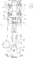
Fig. 1 is a plan view of a sliding bogie link trailer according to the invention; -
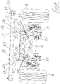
Fig. 2 is another plan view of the sliding bogie link trailer, shown in another position of use; -
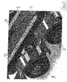
Fig. 3 is a detail perspective view showing a sliding bogie portion of the link trailer; -
Fig. 4 is an enlarged detail elevational view showing portion of the sliding bogie link trailer; -
Fig. 5 is a detail elevational view showing a sensing means portion of the sliding bogie link trailer; -
Fig. 6 is a detail sectional view taken along the line VI-VI ofFig. 5 showing the sensing means portion of the sliding bogie link trailer; -
Fig. 7 is a detail plan view showing a locking portion of the sliding bogie link trailer; -
Fig. 8 is a perspective view of the locking portion shown inFig. 7 ; -
Fig. 9 is an exploded elevational view of the sliding bogie link trailer; -
Fig. 10 is an elevational view of the sliding bogie link trailer, shown in an open position; -
Fig. 11 is an elevational view of the sliding bogie link trailer, shown in a closed position; -
Fig. 12 is a detail elevational view showing portion of the sliding bogie link trailer; -
Fig. 13 is a detail perspective view of portion of the sliding bogie link trailer; -
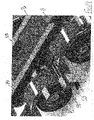
Fig. 14 is a detail perspective view similar to that shown inFig. 13 , showing a step portion of the trailer in another position of use; -
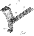
Fig. 15 is a detail perspective view of the step portion; -
Fig. 16 is an elevational view of another sliding bogie link trailer according to a second embodiment of the invention, shown in an open position; and -
Fig. 17 is an elevational view of the sliding bogie link trailer ofFig. 16 , shown in a closed position. - Referring to the drawings, there is shown a sliding bogie link trailer according to the invention, indicated generally by the
reference numeral 1. Thetrailer 1 has afront trailer part 2 and an associatedrear trailer part 3 which are slidably interconnected. - The
rear trailer part 3 forms a sliding bogie which is slidably mounted at a rear end of thefront trailer part 2. Thefront trailer part 2 has akingpin 5 for connection to a fifth wheel of a tractor vehicle (not shown) for towing thetrailer 1. Therear trailer part 3 has a pair of longitudinally spaced-apartaxles engaging road wheels 8. In this case, bothaxles rear trailer part 3 are steer axles having an associated steering system on thetrailer 1 which is operable to steer thewheels 8 on eachaxle Fig. 5 and Fig. 6 ) is provided on thetrailer 1 to sense when therear trailer part 3 is in a fully open position (as shown inFig. 2 ) on thefront trailer part 2. The steering system is operable to lock thewheels 8 at a zero steer angle when therear trailer part 3 is not in the fully open position, that is, when it is in a partially closed position or a fully closed position, as shown inFig. 1 . Afifth wheel 11 is mounted at a rear end of therear trailer part 3 for towing another trailer behind the slidingbogie link trailer 1. - Preferably, the steering system is an electro-hydraulic steering system. A number of electro-hydraulic steer systems are well known, such as the systems produced by the Dutch company VSE Trailer Systems BV (part of the Weber-Hydraulik Group), and will be familiar to those skilled in the art. The VSE steering system is an electronic steering system which provides computer controlled electro-hydraulic steering. Essentially, a track rod cylinder is mounted on each
steer axle wheels 8 on theaxle kingpin 5 measures the yaw angle between the tractor and thetrailer 1 and this is converted into a signal which is used to control operation of the track rod cylinder on eachsteer axle wheels 8 on theaxles - The sensing means 10 comprises a pair of
sensors trailer part trigger arm 16 mounted on theother trailer part sensors rear trailer part 3 and thearm 16 is mounted on thefront trailer part 2. However, it will be appreciated that in an alternative arrangement thesensors front trailer part 2 and thearm 16 mounted on the rear trailer part. Thesensors Fig. 5 ) between thesensors arm 16 when in alignment is in the range 5mm to 10mm. - The
trigger arm 16 aligns with thesensors Fig. 6 , when therear trailer part 3 is in the fully open position shown inFig. 2 . Afirst sensor 14 indicates if therear trailer part 3 is in the fully open position and communicates this to a controller of the electro-hydraulic steering system. Asecond sensor 15 is also connected to the controller of the electro-hydraulic steering system and is operable to reboot the controller of the electro-hydraulic steering system when therear trailer part 3 moves between open and closed positions on thefront trailer part 2. It is envisaged that in some cases asingle sensor wheels 8 at a zero steer angle when therear trailer part 3 is not in the fully open position and allow normal steering of thewheels 8 when therear trailer part 3 is in the fully open position. No manual intervention is required to activate or de-activate the steer system as with conventional steer systems. - Referring in particular to
Fig. 7 andFig. 8 , alocking system 20 for locking therear trailer part 3 on thefront trailer part 2 in either a fully open or a fully closed position is shown. The lockingsystem 20 comprises a pair ofpneumatic ram 23 operated lockingbolts rear trailer part 3 for movement between a retracted release position and an extended engaged position for engagement with complementary receivers on thefront trailer part 2. Eachpneumatic ram 23 comprises a standard 24/30 anchorlok brake chamber. The pneumatic rams 23 are mounted on opposite sides of acentral plate 24 extending longitudinally between spaced-apartcross members chassis 27 of therear trailer part 3. - Referring in particular to
Figs. 1 to 3 and9 to 14 , therear trailer part 3 has achassis 27 comprising a pair of spaced-apart longitudinal I-beams upright web 31 with alower flange 33 and anupper flange 34.Rear rollers 30 are mounted at a rear end of thefront trailer part 2 which roll along a track formed along anupper face 32 of thelower flange 33 of each I-beam rear trailer part 3 outside theweb 31. - Each
rear roller 30 comprises a removablerear roller assembly 35 which is bolted onto thefront trailer part 2 at a rear end of thefront trailer part 2. Thus eachrear roller assembly 35 is removably mounted on thefront trailer part 2. This advantageously facilitates manufacture of thetrailer 1 and assembly of thetrailer parts trailer parts roller assemblies 35. - Referring in particular to
Fig. 1 andFig. 9 , thefront trailer part 2 has askeletal chassis 42 comprising a pair of spaced-apart longitudinal I-beams cross members 45. Each I-beam vertical web 46 with atop flange 47 and abottom flange 48. Bolsters 49, withtwistlocks 50 for engagement with container boxes carried on thefront trailer part 2 in use, project laterally outwardly of the longitudinal I-beams - The two
trailer parts trailer parts Fig. 1 and the fully open position shown inFig. 2 .Forward rollers 37 andintermediate rollers 38 on thefront trailer part 2 run along a top 39 of each I-beam rear trailer part 3.Rollers 40 at a front end of each I-beam rear trailer part 3 roll along upper faces 41 of thebottom flanges 48 of the longitudinal I-beams webs 46 of the I-beams chassis 42 of thefront trailer part 2. - Referring now to
Figs. 13 to 15 , astep assembly 55 is shown mounted between theaxles step assembly 55 is telescopically mounted on therear trailer part 3 for movement between an inward position housed between thewheels 8 and an outward position projecting outwardly at a side of thetrailer 1 to provide access to the coupling area when another trailer is coupled to thefifth wheel 11 on therear trailer part 3. Thestep assembly 55 has aslide arm 56 which is telescopically slidable within acomplementary slide box 57 on therear trailer part 3. A number ofsteps 58 are provided at an outer end of theslide arm 56. - Referring now to
Fig. 16 and Fig. 17 , there is shown another sliding bogie link trailer according to a second embodiment of the invention, indicated generally by thereference numeral 60. Parts similar to those described previously are assigned the same reference numerals. In this case, therear trailer part 3 has three axles, namely, a front fixedaxle 61, anintermediate steer axle 62, and arear steer axle 63. - The terms "comprise" and "include", and any variations thereof required for grammatical reasons, are to be considered as interchangeable and accorded the widest possible interpretation.
- The invention is not limited to the embodiments hereinbefore described but may be varied in both construction and detail within the scope of the appending claims.
Claims (16)
- A sliding bogie link trailer (1) having a front trailer part (2) and a rear trailer part (3) which are slidably interconnected, the front trailer part (2) having a kingpin (5) for connection to a fifth wheel of a tractor vehicle for towing the trailer (1), the rear trailer part (3) having an axle (6, 7) with ground-engaging wheels (8) and a fifth wheel (11) being mounted at a rear end of the rear trailer part (3) for towing another trailer, the axle (6, 7) on the rear trailer part (3) being a steerable axle and having an associated steering system on the trailer (1) which is operable to steer the wheels (8) on the axle (6, 7), the steering system including sensing means (10) to sense when the rear trailer part (3) is in a fully open position on the front trailer part (2), the steering system being operable to lock the wheels (8) at a zero steer angle when the rear trailer part (3) is not in the fully open position.
- The trailer (1) as claimed in claim 1, wherein the steering system is an electro-hydraulic steering system.
- The trailer (1) as claimed in claim 2, wherein two sensors (14, 15) are provided comprising a first sensor (14) to indicate if the rear trailer part (3) is in the fully open position and a second sensor (15) operable to reboot a controller of the electro-hydraulic steering system when the rear trailer part (3) moves between open and closed positions on the front trailer part (2).
- The trailer (1) as claimed in claim 3, wherein the sensing means (10) comprises the two sensors (14, 15) mounted on the rear trailer part (3) and an associated trigger arm (16) mounted on the front trailer part (2), the trigger arm (16) aligning with the sensors (14, 15) when the rear trailer part (3) is in the fully open position.
- The trailer (1) as claimed in any preceding claim, wherein the two trailer parts (2, 3) are slidably interconnected by means of rollers (30, 37, 38, 40).
- The trailer (1) as claimed in claim 5, wherein the rear trailer part (3) has a chassis (27) comprising a pair of spaced-apart longitudinal I-beams (28, 29), and rear rollers (30) mounted at a rear end of the front trailer part (2) roll along a track formed along an upper face (32) of a lower flange (33) of each I-beam (28, 29) on the rear trailer part (3).
- The trailer (1) as claimed in claim 5, wherein each rear roller (30) comprises a removable rear roller assembly (35) demountably attached to the front trailer part (2).
- The trailer (1) as claimed in claim 7, wherein the front trailer part (2) has a chassis (42) comprising a pair of spaced-apart longitudinal I-beams (43, 44) interconnected by cross members (45) and each rear roller assembly (35) is bolted to an inside face of an upright web of an I-beam (43, 44).
- The trailer as claimed in any one of the preceding claims, further comprising a locking system (20) for locking the trailer parts (2, 3) in the fully open position and in a fully closed position.
- The trailer (1) as claimed in claim 9 wherein the locking system (20) comprises at least one locking bolt (21, 22) slidably mounted on one trailer part (2, 3) for movement between a retracted disengaged position and an extended engaged position for engagement with associated spaced-apart receiver slots on the other trailer part (2, 3) corresponding to the fully open position and the fully closed position.
- The trailer (1) as claimed in claim 10 wherein each locking bolt (21, 22) is manually slidable between the retracted disengaged position and the extended engaged position.
- The trailer (1) as claimed in claim 10 wherein an actuator (23) is provided for movement of each locking bolt (21, 22) between the retracted disengaged position and the extended engaged position.
- The trailer (1) as claimed in claim 12, wherein the actuator (23) comprises a mechanism which is operable for reciprocating movement of the locking bolt (21, 22).
- The trailer (1) as claimed in claim 12 or claim 13, wherein a pair of locking bolts (21, 22) are mounted transversely in parallel on the rear trailer part (3) for movement by pneumatic rams (23) between the retracted disengaged position and the extended engaged position for engagement with complementary receivers on the front trailer part (2).
- The trailer (1) as claimed in any one of the preceding claims, wherein two steer axles (6, 7) are mounted on the rear trailer part (3).
- The trailer (60) as clamed in any one of claims 1 to 14, wherein three axles are mounted on the rear trailer part (3) comprising a front fixed axle (61), an intermediate steer axle (62) and a rear steer axle (63).
Applications Claiming Priority (1)
| Application Number | Priority Date | Filing Date | Title |
|---|---|---|---|
| GBGB1916770.9A GB201916770D0 (en) | 2019-11-18 | 2019-11-18 | A sliding bogie link trailer with steer axle |
Publications (2)
| Publication Number | Publication Date |
|---|---|
| EP3858714A1 EP3858714A1 (en) | 2021-08-04 |
| EP3858714B1 true EP3858714B1 (en) | 2022-12-28 |
Family
ID=69063202
Family Applications (1)
| Application Number | Title | Priority Date | Filing Date |
|---|---|---|---|
| EP20208478.6A Active EP3858714B1 (en) | 2019-11-18 | 2020-11-18 | Sliding bogie link trailer with steer axle |
Country Status (6)
| Country | Link |
|---|---|
| EP (1) | EP3858714B1 (en) |
| DK (1) | DK3858714T3 (en) |
| ES (1) | ES2936328T3 (en) |
| GB (1) | GB201916770D0 (en) |
| PL (1) | PL3858714T3 (en) |
| PT (1) | PT3858714T (en) |
Families Citing this family (3)
| Publication number | Priority date | Publication date | Assignee | Title |
|---|---|---|---|---|
| SE542772C2 (en) * | 2018-06-08 | 2020-07-07 | Hoejner Invest Ab | Container carrier |
| WO2023047182A1 (en) * | 2021-09-23 | 2023-03-30 | Raghunandan Selvarathinam | A trailer system for carrying a load |
| US12162363B2 (en) * | 2022-08-25 | 2024-12-10 | Range Energy Inc. | Modular system for dynamic tow and regenerative braking of a trailer |
Family Cites Families (4)
| Publication number | Priority date | Publication date | Assignee | Title |
|---|---|---|---|---|
| FI89148C (en) * | 1984-04-13 | 1993-08-25 | Rolux Oy | Lifting trolley coupled to a towing device |
| GB2396141B (en) * | 2002-12-11 | 2006-11-22 | Kevin William Raven | Extendible positive steer trailer |
| ITTO20060287A1 (en) * | 2006-04-18 | 2007-10-19 | Cometto Ind | TRAILER WITH VARIABLE LENGTH FOR WHEELED DRIVERS |
| IES20080762A2 (en) * | 2008-09-19 | 2011-01-19 | David Dennison | A trailer |
-
2019
- 2019-11-18 GB GBGB1916770.9A patent/GB201916770D0/en not_active Ceased
-
2020
- 2020-11-18 ES ES20208478T patent/ES2936328T3/en active Active
- 2020-11-18 PT PT202084786T patent/PT3858714T/en unknown
- 2020-11-18 DK DK20208478.6T patent/DK3858714T3/en active
- 2020-11-18 EP EP20208478.6A patent/EP3858714B1/en active Active
- 2020-11-18 PL PL20208478.6T patent/PL3858714T3/en unknown
Also Published As
| Publication number | Publication date |
|---|---|
| GB201916770D0 (en) | 2020-01-01 |
| ES2936328T3 (en) | 2023-03-16 |
| EP3858714A1 (en) | 2021-08-04 |
| PL3858714T3 (en) | 2023-02-20 |
| PT3858714T (en) | 2023-02-21 |
| DK3858714T3 (en) | 2023-01-23 |
Similar Documents
| Publication | Publication Date | Title |
|---|---|---|
| EP3858714A1 (en) | Sliding bogie link trailer with steer axle | |
| US4441730A (en) | Steering device for many-axled goose-neck trailers | |
| DE102009002334B4 (en) | Control system with a displacement device for a fifth wheel arranged on a towing vehicle | |
| US8562012B2 (en) | Roll coupling trailer hitch assembly | |
| EP3426545B1 (en) | Drive unit and driving method | |
| CA2129685C (en) | Method and apparatus for connecting a tow vehicle to a trailer having a front axle assembly which pivots about a vertical axis | |
| EP2637914B1 (en) | Heavy duty transport vehicle for iso containers | |
| US11654981B2 (en) | Auxiliary dolly | |
| US8262118B2 (en) | Vehicle power unit and body unit system | |
| US10759321B1 (en) | Extendable trailer | |
| US5163698A (en) | Log trailer load extension axle assembly | |
| US11643139B2 (en) | Method for steering a vehicle | |
| EP0126940B1 (en) | Highway train | |
| NO129192B (en) | ||
| DE102011007943B4 (en) | trailer | |
| EP1897790B1 (en) | Device for coupling a towed vehicle to a towing vehicle, as well as a vehicle combination | |
| EP2165918B1 (en) | A sliding bogie link trailer | |
| DE102010060274A1 (en) | Axle unit, particularly mono-wheel axis device, for loading vehicle such as motor vehicle, trailer or semi-trailer, has support structure as bearing load frame or center pivot plate | |
| US20150266507A1 (en) | Steering lock mechanism for heavy-duty vehicle axle/suspension system | |
| EP0295589B1 (en) | Short coupling system | |
| US11919432B2 (en) | Trailer unit for transporting tracked constructional machines | |
| EP3805079B1 (en) | Split trailer | |
| EP3718862B1 (en) | Vehicle, in particular heavy-duty vehicle | |
| DE3404930A1 (en) | Articulated road train | |
| US20240351646A1 (en) | Twin pump trailer with shifting axles |
Legal Events
| Date | Code | Title | Description |
|---|---|---|---|
| PUAI | Public reference made under article 153(3) epc to a published international application that has entered the european phase |
Free format text: ORIGINAL CODE: 0009012 |
|
| STAA | Information on the status of an ep patent application or granted ep patent |
Free format text: STATUS: THE APPLICATION HAS BEEN PUBLISHED |
|
| AK | Designated contracting states |
Kind code of ref document: A1 Designated state(s): AL AT BE BG CH CY CZ DE DK EE ES FI FR GB GR HR HU IE IS IT LI LT LU LV MC MK MT NL NO PL PT RO RS SE SI SK SM TR |
|
| STAA | Information on the status of an ep patent application or granted ep patent |
Free format text: STATUS: REQUEST FOR EXAMINATION WAS MADE |
|
| 17P | Request for examination filed |
Effective date: 20220204 |
|
| RBV | Designated contracting states (corrected) |
Designated state(s): AL AT BE BG CH CY CZ DE DK EE ES FI FR GB GR HR HU IE IS IT LI LT LU LV MC MK MT NL NO PL PT RO RS SE SI SK SM TR |
|
| GRAP | Despatch of communication of intention to grant a patent |
Free format text: ORIGINAL CODE: EPIDOSNIGR1 |
|
| STAA | Information on the status of an ep patent application or granted ep patent |
Free format text: STATUS: GRANT OF PATENT IS INTENDED |
|
| INTG | Intention to grant announced |
Effective date: 20220620 |
|
| RIC1 | Information provided on ipc code assigned before grant |
Ipc: B62D 13/02 20060101ALI20220606BHEP Ipc: B62D 53/08 20060101ALI20220606BHEP Ipc: B62D 53/06 20060101AFI20220606BHEP |
|
| GRAS | Grant fee paid |
Free format text: ORIGINAL CODE: EPIDOSNIGR3 |
|
| GRAA | (expected) grant |
Free format text: ORIGINAL CODE: 0009210 |
|
| STAA | Information on the status of an ep patent application or granted ep patent |
Free format text: STATUS: THE PATENT HAS BEEN GRANTED |
|
| AK | Designated contracting states |
Kind code of ref document: B1 Designated state(s): AL AT BE BG CH CY CZ DE DK EE ES FI FR GB GR HR HU IE IS IT LI LT LU LV MC MK MT NL NO PL PT RO RS SE SI SK SM TR |
|
| REG | Reference to a national code |
Ref country code: GB Ref legal event code: FG4D |
|
| REG | Reference to a national code |
Ref country code: CH Ref legal event code: EP |
|
| REG | Reference to a national code |
Ref country code: DE Ref legal event code: R096 Ref document number: 602020007196 Country of ref document: DE |
|
| REG | Reference to a national code |
Ref country code: AT Ref legal event code: REF Ref document number: 1540325 Country of ref document: AT Kind code of ref document: T Effective date: 20230115 |
|
| REG | Reference to a national code |
Ref country code: NL Ref legal event code: FP Ref country code: IE Ref legal event code: FG4D |
|
| REG | Reference to a national code |
Ref country code: DK Ref legal event code: T3 Effective date: 20230118 |
|
| REG | Reference to a national code |
Ref country code: RO Ref legal event code: EPE |
|
| REG | Reference to a national code |
Ref country code: SE Ref legal event code: TRGR |
|
| REG | Reference to a national code |
Ref country code: PT Ref legal event code: SC4A Ref document number: 3858714 Country of ref document: PT Date of ref document: 20230221 Kind code of ref document: T Free format text: AVAILABILITY OF NATIONAL TRANSLATION Effective date: 20230215 |
|
| REG | Reference to a national code |
Ref country code: ES Ref legal event code: FG2A Ref document number: 2936328 Country of ref document: ES Kind code of ref document: T3 Effective date: 20230316 |
|
| REG | Reference to a national code |
Ref country code: LT Ref legal event code: MG9D |
|
| PG25 | Lapsed in a contracting state [announced via postgrant information from national office to epo] |
Ref country code: NO Free format text: LAPSE BECAUSE OF FAILURE TO SUBMIT A TRANSLATION OF THE DESCRIPTION OR TO PAY THE FEE WITHIN THE PRESCRIBED TIME-LIMIT Effective date: 20230328 Ref country code: LT Free format text: LAPSE BECAUSE OF FAILURE TO SUBMIT A TRANSLATION OF THE DESCRIPTION OR TO PAY THE FEE WITHIN THE PRESCRIBED TIME-LIMIT Effective date: 20221228 Ref country code: FI Free format text: LAPSE BECAUSE OF FAILURE TO SUBMIT A TRANSLATION OF THE DESCRIPTION OR TO PAY THE FEE WITHIN THE PRESCRIBED TIME-LIMIT Effective date: 20221228 |
|
| PG25 | Lapsed in a contracting state [announced via postgrant information from national office to epo] |
Ref country code: RS Free format text: LAPSE BECAUSE OF FAILURE TO SUBMIT A TRANSLATION OF THE DESCRIPTION OR TO PAY THE FEE WITHIN THE PRESCRIBED TIME-LIMIT Effective date: 20221228 Ref country code: LV Free format text: LAPSE BECAUSE OF FAILURE TO SUBMIT A TRANSLATION OF THE DESCRIPTION OR TO PAY THE FEE WITHIN THE PRESCRIBED TIME-LIMIT Effective date: 20221228 Ref country code: HR Free format text: LAPSE BECAUSE OF FAILURE TO SUBMIT A TRANSLATION OF THE DESCRIPTION OR TO PAY THE FEE WITHIN THE PRESCRIBED TIME-LIMIT Effective date: 20221228 Ref country code: GR Free format text: LAPSE BECAUSE OF FAILURE TO SUBMIT A TRANSLATION OF THE DESCRIPTION OR TO PAY THE FEE WITHIN THE PRESCRIBED TIME-LIMIT Effective date: 20230329 |
|
| PG25 | Lapsed in a contracting state [announced via postgrant information from national office to epo] |
Ref country code: SM Free format text: LAPSE BECAUSE OF FAILURE TO SUBMIT A TRANSLATION OF THE DESCRIPTION OR TO PAY THE FEE WITHIN THE PRESCRIBED TIME-LIMIT Effective date: 20221228 Ref country code: EE Free format text: LAPSE BECAUSE OF FAILURE TO SUBMIT A TRANSLATION OF THE DESCRIPTION OR TO PAY THE FEE WITHIN THE PRESCRIBED TIME-LIMIT Effective date: 20221228 |
|
| PG25 | Lapsed in a contracting state [announced via postgrant information from national office to epo] |
Ref country code: SK Free format text: LAPSE BECAUSE OF FAILURE TO SUBMIT A TRANSLATION OF THE DESCRIPTION OR TO PAY THE FEE WITHIN THE PRESCRIBED TIME-LIMIT Effective date: 20221228 Ref country code: IS Free format text: LAPSE BECAUSE OF FAILURE TO SUBMIT A TRANSLATION OF THE DESCRIPTION OR TO PAY THE FEE WITHIN THE PRESCRIBED TIME-LIMIT Effective date: 20230428 Ref country code: AL Free format text: LAPSE BECAUSE OF FAILURE TO SUBMIT A TRANSLATION OF THE DESCRIPTION OR TO PAY THE FEE WITHIN THE PRESCRIBED TIME-LIMIT Effective date: 20221228 |
|
| REG | Reference to a national code |
Ref country code: DE Ref legal event code: R097 Ref document number: 602020007196 Country of ref document: DE |
|
| PLBE | No opposition filed within time limit |
Free format text: ORIGINAL CODE: 0009261 |
|
| STAA | Information on the status of an ep patent application or granted ep patent |
Free format text: STATUS: NO OPPOSITION FILED WITHIN TIME LIMIT |
|
| 26N | No opposition filed |
Effective date: 20230929 |
|
| PG25 | Lapsed in a contracting state [announced via postgrant information from national office to epo] |
Ref country code: SI Free format text: LAPSE BECAUSE OF FAILURE TO SUBMIT A TRANSLATION OF THE DESCRIPTION OR TO PAY THE FEE WITHIN THE PRESCRIBED TIME-LIMIT Effective date: 20221228 |
|
| REG | Reference to a national code |
Ref country code: CH Ref legal event code: PL |
|
| PG25 | Lapsed in a contracting state [announced via postgrant information from national office to epo] |
Ref country code: MC Free format text: LAPSE BECAUSE OF FAILURE TO SUBMIT A TRANSLATION OF THE DESCRIPTION OR TO PAY THE FEE WITHIN THE PRESCRIBED TIME-LIMIT Effective date: 20221228 |
|
| PG25 | Lapsed in a contracting state [announced via postgrant information from national office to epo] |
Ref country code: LU Free format text: LAPSE BECAUSE OF NON-PAYMENT OF DUE FEES Effective date: 20231118 |
|
| PG25 | Lapsed in a contracting state [announced via postgrant information from national office to epo] |
Ref country code: CH Free format text: LAPSE BECAUSE OF NON-PAYMENT OF DUE FEES Effective date: 20231130 |
|
| PG25 | Lapsed in a contracting state [announced via postgrant information from national office to epo] |
Ref country code: MC Free format text: LAPSE BECAUSE OF FAILURE TO SUBMIT A TRANSLATION OF THE DESCRIPTION OR TO PAY THE FEE WITHIN THE PRESCRIBED TIME-LIMIT Effective date: 20221228 Ref country code: LU Free format text: LAPSE BECAUSE OF NON-PAYMENT OF DUE FEES Effective date: 20231118 Ref country code: CH Free format text: LAPSE BECAUSE OF NON-PAYMENT OF DUE FEES Effective date: 20231130 |
|
| PG25 | Lapsed in a contracting state [announced via postgrant information from national office to epo] |
Ref country code: FR Free format text: LAPSE BECAUSE OF NON-PAYMENT OF DUE FEES Effective date: 20231130 |
|
| PG25 | Lapsed in a contracting state [announced via postgrant information from national office to epo] |
Ref country code: FR Free format text: LAPSE BECAUSE OF NON-PAYMENT OF DUE FEES Effective date: 20231130 |
|
| PG25 | Lapsed in a contracting state [announced via postgrant information from national office to epo] |
Ref country code: BG Free format text: LAPSE BECAUSE OF FAILURE TO SUBMIT A TRANSLATION OF THE DESCRIPTION OR TO PAY THE FEE WITHIN THE PRESCRIBED TIME-LIMIT Effective date: 20221228 |
|
| PG25 | Lapsed in a contracting state [announced via postgrant information from national office to epo] |
Ref country code: BG Free format text: LAPSE BECAUSE OF FAILURE TO SUBMIT A TRANSLATION OF THE DESCRIPTION OR TO PAY THE FEE WITHIN THE PRESCRIBED TIME-LIMIT Effective date: 20221228 |
|
| PG25 | Lapsed in a contracting state [announced via postgrant information from national office to epo] |
Ref country code: CY Free format text: LAPSE BECAUSE OF FAILURE TO SUBMIT A TRANSLATION OF THE DESCRIPTION OR TO PAY THE FEE WITHIN THE PRESCRIBED TIME-LIMIT; INVALID AB INITIO Effective date: 20201118 |
|
| PG25 | Lapsed in a contracting state [announced via postgrant information from national office to epo] |
Ref country code: HU Free format text: LAPSE BECAUSE OF FAILURE TO SUBMIT A TRANSLATION OF THE DESCRIPTION OR TO PAY THE FEE WITHIN THE PRESCRIBED TIME-LIMIT; INVALID AB INITIO Effective date: 20201118 |
|
| PGFP | Annual fee paid to national office [announced via postgrant information from national office to epo] |
Ref country code: PT Payment date: 20251119 Year of fee payment: 6 |
|
| PG25 | Lapsed in a contracting state [announced via postgrant information from national office to epo] |
Ref country code: TR Free format text: LAPSE BECAUSE OF FAILURE TO SUBMIT A TRANSLATION OF THE DESCRIPTION OR TO PAY THE FEE WITHIN THE PRESCRIBED TIME-LIMIT Effective date: 20221228 |
|
| PGFP | Annual fee paid to national office [announced via postgrant information from national office to epo] |
Ref country code: NL Payment date: 20251127 Year of fee payment: 6 |
|
| PGFP | Annual fee paid to national office [announced via postgrant information from national office to epo] |
Ref country code: DE Payment date: 20251117 Year of fee payment: 6 |
|
| PGFP | Annual fee paid to national office [announced via postgrant information from national office to epo] |
Ref country code: GB Payment date: 20251128 Year of fee payment: 6 |
|
| PGFP | Annual fee paid to national office [announced via postgrant information from national office to epo] |
Ref country code: AT Payment date: 20251125 Year of fee payment: 6 |
|
| PGFP | Annual fee paid to national office [announced via postgrant information from national office to epo] |
Ref country code: IT Payment date: 20251201 Year of fee payment: 6 Ref country code: DK Payment date: 20251114 Year of fee payment: 6 |
|
| PGFP | Annual fee paid to national office [announced via postgrant information from national office to epo] |
Ref country code: BE Payment date: 20251127 Year of fee payment: 6 |
|
| PGFP | Annual fee paid to national office [announced via postgrant information from national office to epo] |
Ref country code: SE Payment date: 20251114 Year of fee payment: 6 |
|
| PGFP | Annual fee paid to national office [announced via postgrant information from national office to epo] |
Ref country code: CZ Payment date: 20251020 Year of fee payment: 6 Ref country code: IE Payment date: 20251114 Year of fee payment: 6 |
|
| PGFP | Annual fee paid to national office [announced via postgrant information from national office to epo] |
Ref country code: PL Payment date: 20251103 Year of fee payment: 6 |
|
| PGFP | Annual fee paid to national office [announced via postgrant information from national office to epo] |
Ref country code: RO Payment date: 20251110 Year of fee payment: 6 |
|
| PGFP | Annual fee paid to national office [announced via postgrant information from national office to epo] |
Ref country code: ES Payment date: 20251201 Year of fee payment: 6 |
|
| REG | Reference to a national code |
Ref country code: AT Ref legal event code: UEP Ref document number: 1540325 Country of ref document: AT Kind code of ref document: T Effective date: 20221228 |