EP3858684A1 - Expanded tube for a motor vehicle crash box and manufacturing method for it - Google Patents
Expanded tube for a motor vehicle crash box and manufacturing method for it Download PDFInfo
- Publication number
- EP3858684A1 EP3858684A1 EP20154182.8A EP20154182A EP3858684A1 EP 3858684 A1 EP3858684 A1 EP 3858684A1 EP 20154182 A EP20154182 A EP 20154182A EP 3858684 A1 EP3858684 A1 EP 3858684A1
- Authority
- EP
- European Patent Office
- Prior art keywords
- crash box
- tube
- motor vehicle
- zones
- expanded
- Prior art date
- Legal status (The legal status is an assumption and is not a legal conclusion. Google has not performed a legal analysis and makes no representation as to the accuracy of the status listed.)
- Granted
Links
Images


Classifications
-
- B—PERFORMING OPERATIONS; TRANSPORTING
- B21—MECHANICAL METAL-WORKING WITHOUT ESSENTIALLY REMOVING MATERIAL; PUNCHING METAL
- B21C—MANUFACTURE OF METAL SHEETS, WIRE, RODS, TUBES, PROFILES OR LIKE SEMI-MANUFACTURED PRODUCTS OTHERWISE THAN BY ROLLING; AUXILIARY OPERATIONS USED IN CONNECTION WITH METAL-WORKING WITHOUT ESSENTIALLY REMOVING MATERIAL
- B21C37/00—Manufacture of metal sheets, rods, wire, tubes, profiles or like semi-manufactured products, not otherwise provided for; Manufacture of tubes of special shape
- B21C37/06—Manufacture of metal sheets, rods, wire, tubes, profiles or like semi-manufactured products, not otherwise provided for; Manufacture of tubes of special shape of tubes or metal hoses; Combined procedures for making tubes, e.g. for making multi-wall tubes
- B21C37/15—Making tubes of special shape; Making tube fittings
- B21C37/16—Making tubes with varying diameter in longitudinal direction
-
- B—PERFORMING OPERATIONS; TRANSPORTING
- B21—MECHANICAL METAL-WORKING WITHOUT ESSENTIALLY REMOVING MATERIAL; PUNCHING METAL
- B21C—MANUFACTURE OF METAL SHEETS, WIRE, RODS, TUBES, PROFILES OR LIKE SEMI-MANUFACTURED PRODUCTS OTHERWISE THAN BY ROLLING; AUXILIARY OPERATIONS USED IN CONNECTION WITH METAL-WORKING WITHOUT ESSENTIALLY REMOVING MATERIAL
- B21C37/00—Manufacture of metal sheets, rods, wire, tubes, profiles or like semi-manufactured products, not otherwise provided for; Manufacture of tubes of special shape
- B21C37/06—Manufacture of metal sheets, rods, wire, tubes, profiles or like semi-manufactured products, not otherwise provided for; Manufacture of tubes of special shape of tubes or metal hoses; Combined procedures for making tubes, e.g. for making multi-wall tubes
- B21C37/08—Making tubes with welded or soldered seams
- B21C37/0803—Making tubes with welded or soldered seams the tubes having a special shape, e.g. polygonal tubes
-
- B—PERFORMING OPERATIONS; TRANSPORTING
- B21—MECHANICAL METAL-WORKING WITHOUT ESSENTIALLY REMOVING MATERIAL; PUNCHING METAL
- B21D—WORKING OR PROCESSING OF SHEET METAL OR METAL TUBES, RODS OR PROFILES WITHOUT ESSENTIALLY REMOVING MATERIAL; PUNCHING METAL
- B21D41/00—Application of procedures in order to alter the diameter of tube ends
- B21D41/02—Enlarging
-
- B—PERFORMING OPERATIONS; TRANSPORTING
- B60—VEHICLES IN GENERAL
- B60R—VEHICLES, VEHICLE FITTINGS, OR VEHICLE PARTS, NOT OTHERWISE PROVIDED FOR
- B60R19/00—Wheel guards; Radiator guards, e.g. grilles; Obstruction removers; Fittings damping bouncing force in collisions
- B60R19/02—Bumpers, i.e. impact receiving or absorbing members for protecting vehicles or fending off blows from other vehicles or objects
- B60R19/03—Bumpers, i.e. impact receiving or absorbing members for protecting vehicles or fending off blows from other vehicles or objects characterised by material, e.g. composite
-
- B—PERFORMING OPERATIONS; TRANSPORTING
- B60—VEHICLES IN GENERAL
- B60R—VEHICLES, VEHICLE FITTINGS, OR VEHICLE PARTS, NOT OTHERWISE PROVIDED FOR
- B60R19/00—Wheel guards; Radiator guards, e.g. grilles; Obstruction removers; Fittings damping bouncing force in collisions
- B60R19/02—Bumpers, i.e. impact receiving or absorbing members for protecting vehicles or fending off blows from other vehicles or objects
- B60R19/24—Arrangements for mounting bumpers on vehicles
- B60R19/26—Arrangements for mounting bumpers on vehicles comprising yieldable mounting means
- B60R19/34—Arrangements for mounting bumpers on vehicles comprising yieldable mounting means destroyed upon impact, e.g. one-shot type
-
- C—CHEMISTRY; METALLURGY
- C21—METALLURGY OF IRON
- C21D—MODIFYING THE PHYSICAL STRUCTURE OF FERROUS METALS; GENERAL DEVICES FOR HEAT TREATMENT OF FERROUS OR NON-FERROUS METALS OR ALLOYS; MAKING METAL MALLEABLE, e.g. BY DECARBURISATION OR TEMPERING
- C21D6/00—Heat treatment of ferrous alloys
- C21D6/002—Heat treatment of ferrous alloys containing Cr
-
- C—CHEMISTRY; METALLURGY
- C21—METALLURGY OF IRON
- C21D—MODIFYING THE PHYSICAL STRUCTURE OF FERROUS METALS; GENERAL DEVICES FOR HEAT TREATMENT OF FERROUS OR NON-FERROUS METALS OR ALLOYS; MAKING METAL MALLEABLE, e.g. BY DECARBURISATION OR TEMPERING
- C21D7/00—Modifying the physical properties of iron or steel by deformation
- C21D7/02—Modifying the physical properties of iron or steel by deformation by cold working
- C21D7/10—Modifying the physical properties of iron or steel by deformation by cold working of the whole cross-section, e.g. of concrete reinforcing bars
- C21D7/12—Modifying the physical properties of iron or steel by deformation by cold working of the whole cross-section, e.g. of concrete reinforcing bars by expanding tubular bodies
-
- C—CHEMISTRY; METALLURGY
- C21—METALLURGY OF IRON
- C21D—MODIFYING THE PHYSICAL STRUCTURE OF FERROUS METALS; GENERAL DEVICES FOR HEAT TREATMENT OF FERROUS OR NON-FERROUS METALS OR ALLOYS; MAKING METAL MALLEABLE, e.g. BY DECARBURISATION OR TEMPERING
- C21D9/00—Heat treatment, e.g. annealing, hardening, quenching or tempering, adapted for particular articles; Furnaces therefor
- C21D9/08—Heat treatment, e.g. annealing, hardening, quenching or tempering, adapted for particular articles; Furnaces therefor for tubular bodies or pipes
-
- C—CHEMISTRY; METALLURGY
- C21—METALLURGY OF IRON
- C21D—MODIFYING THE PHYSICAL STRUCTURE OF FERROUS METALS; GENERAL DEVICES FOR HEAT TREATMENT OF FERROUS OR NON-FERROUS METALS OR ALLOYS; MAKING METAL MALLEABLE, e.g. BY DECARBURISATION OR TEMPERING
- C21D9/00—Heat treatment, e.g. annealing, hardening, quenching or tempering, adapted for particular articles; Furnaces therefor
- C21D9/50—Heat treatment, e.g. annealing, hardening, quenching or tempering, adapted for particular articles; Furnaces therefor for welded joints
-
- F—MECHANICAL ENGINEERING; LIGHTING; HEATING; WEAPONS; BLASTING
- F16—ENGINEERING ELEMENTS AND UNITS; GENERAL MEASURES FOR PRODUCING AND MAINTAINING EFFECTIVE FUNCTIONING OF MACHINES OR INSTALLATIONS; THERMAL INSULATION IN GENERAL
- F16F—SPRINGS; SHOCK-ABSORBERS; MEANS FOR DAMPING VIBRATION
- F16F7/00—Vibration-dampers; Shock-absorbers
- F16F7/12—Vibration-dampers; Shock-absorbers using plastic deformation of members
- F16F7/125—Units with a telescopic-like action as one member moves into, or out of a second member
-
- C—CHEMISTRY; METALLURGY
- C21—METALLURGY OF IRON
- C21D—MODIFYING THE PHYSICAL STRUCTURE OF FERROUS METALS; GENERAL DEVICES FOR HEAT TREATMENT OF FERROUS OR NON-FERROUS METALS OR ALLOYS; MAKING METAL MALLEABLE, e.g. BY DECARBURISATION OR TEMPERING
- C21D2211/00—Microstructure comprising significant phases
- C21D2211/001—Austenite
-
- C—CHEMISTRY; METALLURGY
- C21—METALLURGY OF IRON
- C21D—MODIFYING THE PHYSICAL STRUCTURE OF FERROUS METALS; GENERAL DEVICES FOR HEAT TREATMENT OF FERROUS OR NON-FERROUS METALS OR ALLOYS; MAKING METAL MALLEABLE, e.g. BY DECARBURISATION OR TEMPERING
- C21D2221/00—Treating localised areas of an article
Definitions
- the present invention relates to a motor vehicle crash box with a working direction in the longitudinal axis of the motor vehicle.
- the present invention further relates to the manufacturing method of such a component.
- State-of-the-art motor vehicles are equipped at each end of their length or longest dimension (front and rear ends) with energy absorption elements as crash-protection parts.
- Such elements are called crash-management systems or bumper systems and are typically attached to one another by one cross member connected with two state-of-the-art crash boxes, which in turn are connected with the car body construction.
- the crash boxes absorb kinetic crash energy during an impact.
- the crash boxes are irreversibly plasticly deformed by compressing or folding. As a result, the car body itself should be protected without any structural damage or distortion.
- the component crash box as one part of the motor vehicle typically has different, partially seemingly contrary properties like enabling high crash-safety while at the same time being light in weight to reduce fuel consumption and thereby reduce CO 2 emissions, and being cost-effective. Moreover, the crash box provides protection to pedestrians. Further requirements for this component are easy assembly with the neighboring parts, optimal space utilization and the component should be easily replaceable after an impact.
- the "Research Council for Automobile Repairs" developed a test scenario called RCAR crash test to evaluate damage and repairing costs after rear-impact crashes and collisions at lower speed levels. The result of such tests has a direct influence on the insurance rating of passenger vehicles and is therefore of considerable interest to end-users.
- Circular and polygonal tubes as well as modular designs with multi-chamber profiles or box-shape constructions which can be conically tapered in the longitudinal direction of the component. While homogeneous tube profiles provide constant force absorption, the resistance against cross-forces and bending torque is lower than for profiles of other geometries. Tubes present the easiest producible and therefore most cost-effective geometry for crash boxes.
- US patent application publication US2017113638A1 describes a cross member which is made of light metal alloy and configured as a hollow profile to define an interior space and which has a top beam and a bottom beam, with the top beam and/or bottom beam having a recess defined by a marginal area in the form of a collar oriented into an interior space of the cross member.
- a crash box Arranged at an end of the cross member is a crash box formed with a flange sized to overlap at least one region of the cross member in motor vehicle longitudinal direction.
- a spacer is arranged in the interior space of the cross member and has a chamfer for formfitting engagement by the collar.
- a fastener is configured for passage of the recess and thereby extending in a motor vehicle vertical direction through the flange of each crash box and the spacer.
- US patent application publication 2013119705A1 discloses a crash box system in which a multiple chamber profile is used with the integration of an additional support element as well as a fastening profile. Also the integration of weakening tools and longitudinal rips, known from the US patent application publication 2013048455A1 demonstrates an additional effort during component manufacturing resulting in higher component costs.
- US patent application 2011291431A1 describes a crash box using manganese-boron alloyed steel grade, which must be press-hardened and further annealed between 300 - 450°C. Such grades have the technical disadvantage of being brittle even in their weld zones because of their martensitic microstructure having a significantly lower energy absorption potential than grades with an austenitic, ductile microstructure. Moreover, the manufacturing process of press-hardening plus further annealing results in cost-expensive production with inefficient cycle times, high investment costs and unsatisfactory impact on life cycle assessment.
- a tube e.g. a circular tube or polygonal tube
- steel which has a homogenous austenitic microstructure with a strain hardening effect even after forming.
- the crash box of the present invention is easy to assemble and scalable depending on the vehicle model and its dimensions.
- the present invention relates to a motor vehicle crash box with a working direction in the longitudinal axis of the motor vehicle, and a manufacturing method thereof.
- the invention is defined by what is disclosed in the independent claims. Preferable embodiments are set out in the dependent claims.
- the present invention relates to a motor vehicle crash box with a working direction in vehicle's longitudinal axis manufactured out of a tube, e.g. a circular tube or a polygonal tube, which is expanded into different zones different in strength and diameter by using steel which has even after forming a homogenous one-phase microstructure with a strain hardening effect, for example a homogenous austenitic microstructure.
- a tube e.g. a circular tube or a polygonal tube
- the present invention further relates to the manufacturing method of such a component.
- Embodiments describe a motor vehicle crash box.
- the motor vehicle crash box has a working direction in a vehicle's longitudinal axis.
- the motor vehicle crash box is manufactured out of a tube which is expanded by a forming process into an expanded tube having at least two zones having different material strength and different geometry.
- the crash box comprises an expanded tube having at least two zones. Each of the zones has different material strength and a different shape or geometry.
- the tube is a circular tube.
- the tube is a polygonal tube.
- a circular tube is a tube in which both the lumen or inside space of the tube and the outer circumference of the tube are circular and of non-fluctuating diameter.
- the inside space of the tube has a diameter which is essentially the same along the length of the tube and similarly the tube has an external diameter which is essentially the same along the length of the tube.
- the zones have a strength [N/mm 2 ] to diameter [mm] ratio of 6.0 - 9.0 N/mm 3 .
- the strengths are measured by the method according to DIN EN 10216 in which a steel tensile test of one zone of the tube is carried out under quasi-static conditions at room temperature.
- the hardening behavior of stable one-phase steel is known from tensile tests according to DIN EN ISO 6892-1:2017-02, which are carried out under flat sheet conditions, quasi-static conditions and a room temperature.
- between the different zones is a minimum strength delta of ⁇ Rm ⁇ 75MPa, preferably ⁇ Rm ⁇ 120MPa, measured according to the methods described above.
- the differences in strengths between the zones are optimized to result in crumple zones for absorbing kinetic crash energy, as described in the following embodiment in which the expanded tube with its different zones is firstly folded by the zone having the smallest diameter, followed by the others depending on the respectively smallest diameter.
- the zones have a foldability which is inversely proportional to the diameter of the zone. This means that the zone with the smallest diameter folds first and the zone with largest diameter folds last on an impact.
- the expanded tube is configured to provide a residual safety area by reaching a block length of the system, preferably L B ⁇ 80 mm, more preferably L B ⁇ 100 mm, after impact. This limits the transfer of forces into a passenger compartment of a vehicle.
- the center in the longitudinal direction works as a mirror axis and the zones are characterized in a way that starting from the outer-sides to the center, the diameter of the zone decreases towards the center.
- At least one end of the expanded tube is widened to provide a flange around the circumference of the end of the tube, the flange being essentially perpendicular to the longitudinal axis of the tube box and its working direction.
- the flange provides a surface for attaching the crash box to a neighboring vehicle part, for example to a bumper or to the chassis of a car.
- the flange can be, for example, welded as a fillet on the lap joint or mechanically attached in lap joint condition to the neighboring vehicle parts, for example by screws or other mechanical attachments, like rivets, nails, nuts, bolts etc. Such attachment means provide for easy assembly and minimize costs downstream when installing a crash box in a motor vehicle.
- Welded tubes in general cost significantly less than cold drawn seamless tubes. Welding, in particular high-frequency welding offers the highest production speed. Further, high-frequency welding has the lowest possible heat input.
- the heat input in this method is concentrated at the surfaces to be welded. This concentration of the heat input makes the method ideal for welding thin tubes, e.g. tubes having a steel thickness of 0.8mm ⁇ t ⁇ 2.5mm. Thermal distortion is reduced and internal stresses of the tubes are lowered.
- the tube is expanded by a mechanical drift expanding process in a mechanical drift expanding process machine.
- Mechanical drift expanding process machines are relatively inexpensive. Mechanical drift expanding process machines can be used both for testing quality of weld seams and for carrying out the expanding forming step.
- the mechanical drift expanding process machine uses at least two different expanding mandrels for at least two different zones of the crash box. The use of different mandrels optimizes the process.
- the mechanical drift expanding process machine has a mirrored longitudinal axis to create a symmetrical crash box.
- the tube is manufactured out of strain-hardenable, fully austenitic steels, preferably austenitic stainless steels, having an initial yield strength R p0.2 ⁇ 380 MPa and an initial elongation A 80 ⁇ 40 %, measured by the tensile test according to DIN EN ISO 6892-1:2017-02 under flat sheet conditions, quasi-static and at room temperature.
- the tube has an initial thickness of 0.8mm ⁇ t ⁇ 2.5mm and the ratio of the initial diameter to the thickness is 24 ⁇ r d/t ⁇ 125, more preferably between 40 ⁇ r d/t ⁇ 55.
- the thickness and diameter may be measured by various means known to those skilled in the art, e.g. with a caliper or with a mechanical outside micrometer, a further method of measuring the diameter could be an optical method, such as a laser distance measurement method.
- the described thickness and internal diameter ratios are optimal for forming crashboxes for use in passenger cars, trucks, buses or in agricultural vehicles.
- FIG. 1 One embodiment describes the use of an expanded tube as a crash box in a motor vehicle.
- the motor vehicle in which the crash box is integrated is a passenger car, a truck, a bus or an agricultural vehicle.
- the motor vehicle in which the crash box is integrated is a battery electric vehicle.
- the crash box is used as an energy absorbing element in a crash barrier, guardrail or inside a railway vehicle.
- the expanded tube crash box is manufactured out of a longitudinally welded continuous tube, preferably a circular tube whereby the continuous manufactured tube is cut in a first step to the later needed component length.
- the tube cut to the component length is then expanded by a mechanical drift expanding process from at least one side of the tube, preferably from both ends of the tube.
- the longitudinal welding process is preferably a high-frequency welding process which further provides high ductility and power transmission in the welded zones by using austenitic steels.
- a laser beam welding process can be used to fulfill the method of the present invention.
- the cut tube is expanded by a forming process, preferably by a mechanical drift expanding process, into at least two zones different in material strength and geometry, especially in tube diameter.
- a forming process preferably by a mechanical drift expanding process
- the higher expanded zone with a higher resulting diameter offers a higher strength level.
- the expanded tube crash box will fold together, whereby the zone with the smallest diameter and therefore the lowest strength level will fold first. Because there is at the same time the highest elongation in this zone, the potential for energy absorption which means converting the kinetic impact energy into material-related plastic deformation is at its highest.
- the crash box absorbs kinetic impact energy such that the car body and particularly an occupant in the car is not affected by the.
- the resistance against the impact will increase in two ways with the crash box and method of the present invention: Firstly, on a material-related way because the used strain-hardening austenitic steels will increase in strength during the affecting impact because of their hardening mechanism. With this effect, a ratio of yield strength [N/mm 2 ] to diameter of the respective zone [mm] can be defined as design factor for the component engineers. For the method of the present invention with the combination of an expanded tube crash box and strain-hardenable austenitic steels, the ratio is suitable between 6.0 - 9.0 N/mm 3 .
- the resistance against the impact will increase in a second way which is geometry related because the continuous folding of the lower diameter zone into the higher diameter zones results in the effect that more material must be folded during the respective next folding step.
- a component condition is reached where a block length L B is attained which can be defined as a residual safety area at which the maximum resistance against the impact acts.
- the block length of the crash box is reached at a length of L B ⁇ 80 mm, more preferably L B ⁇ 100 mm.
- a minimum strength delta between the different zones is performed.
- the machine is designed with tools having at least two different expanding mandrels for at least two different zones of the crash box. It is preferable that the total mandrel tool is able to shape one side of the mirror axis with one insertion of the tube into the tool. To realize a fast and cost-effective production for high vehicle volumes, it is further preferably that the machine has a mirrored longitudinal axis to create a symmetrical crash box enabling an insertion with mandrel tools from both sides of the longitudinal axis of the tube so that from both sides the tube is expanded simultaneously to its mirror axis.
- At least one end, but preferably both ends, of the expanded tube is widened to provide a flange around the circumference of the end of the tube, the flange being essentially perpendicular to the longitudinal axis of the tube box and its working direction.
- the flange provides a surface for attaching the crash box to a neighboring vehicle part, for example to a bumper or to the chassis of a car.
- the flange can be, for example, welded as a fillet on the lap joint or mechanically attached in lap joint condition to the neighboring vehicle parts, for example by screws or other mechanical attachments, like rivets, nails, nuts, bolts etc.
- Such attachment means provide for easy assembly and minimize costs downstream when installing a crash box in a motor vehicle.
- the benefit of such design is that the position and orientation of the joints is optimized to better resist stresses during an impact from the front or rear of the vehicle.
- the initial material form before tube manufacturing is a flat steel with a thickness t ⁇ 3.0 mm, preferably between 0.8 mm ⁇ t ⁇ 2.5 mm and is typically provided to the tube manufacturer in the form of a coil or a strip. It is further suitable to define a ratio of the initial diameter of the tube to the thickness which is 24 ⁇ r d/t ⁇ 125, preferably between 40 ⁇ r d/t ⁇ 55. It is possible to manufacture single tubes out of sheets or plates, however, the use of strips and coils as starting materials for continuous tube manufacturing provides a cost-effective and large-scaled industrial crash box manufacturing for bigger vehicle volumes.
- cold-formable and strain-hardenable austenitic steels preferably stainless steels, having an initial yield strength R p0.2 ⁇ 380MPa and an initial elongation A 80 ⁇ 45 % are used.
- stable one-phase austenitic steels are used, fully austenitic even after forming and welding offering a TWIP (Twinning induced Plasticity) strain-hardening effect.
- ductility described as elongation after fracture with a value of A 80 ⁇ 40 %, preferably A 80 ⁇ 50 %, is suitable for the initial material of the present invention.
- the needed combination of strength and elongation is given by steels with an austenitic microstructure and a strain-hardening mechanism, especially by austenitic stainless steels, having a chromium content Cr ⁇ 10.5%.
- the characteristic of strain-hardening gives the vehicle engineer the possibility to reach the final strength-ductility combination after finalizing component manufacturing, in this case after expanding the tube crash box.
- the first hardening takes place during cold-forming including manufacturing and the second hardening takes place on crash impact during the lifetime of the component.
- Steels with a metastable austenitic microstructure have the hardening effect of TRIP ( TR ansformation I nduced P lasticity) where the austenite changes into martensite during a forming load.
- TRIP TR ansformation I nduced P lasticity
- steels with a fully austenitic microstructure having a so-called TWIP ( TW inning I nduced P lasticity) hardening effect, which is combined with a specific stacking fault energy (SFE) between 20 and 30 mJ/m 2 are used.
- TWIP hardening austenitic steels is that during tube expanding, the microstructure stays in the initial ductile-austenitic condition without brittle martensitic phases and therefore the component has a homogeneous microstructure.
- austenitic stainless steels offer a significant higher corrosion resistance than low- or unalloyed steels because of their natural and repassivating chromium-oxide-surface layer. An additional dip-coating process of the component is thus avoided and the total costs of the crash box component are therefore reduced. In addition the life cycle environmental impact can be improved.
- the stainless steel crash box component is completely recyclable; it can be melted in an electric arc furnace at the end of the component's life.
- the expanded tube crash box can be used in every motor vehicle, preferably inside a passenger car, but also inside trucks, buses or agricultural vehicles. It is further possible to adapt the method of the present invention by changing the thicknesses and diameters to higher values to enable usage inside railway vehicles. Moreover, the expanded tube crash box could be also integrated into crash barrier or guardrail systems as energy absorbing elements to protect intruding vehicles and their occupants during a collision.
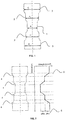
- Fig. 1 illustrates from the side view the expanded tube crash box after manufacturing.
- the dotted line demonstrates the longitudinal symmetry axis.
- Fig. 2 illustrates for the component showed in fig. 1 the relation of strength in longitudinal direction of the component with the different zones whereby transition zones (4) are located between the main zones (1), (2) and (3) from Fig. 1 .
- the transversal dotted lines (5) demonstrate the starting points where a change of the zone and therefore a change in diameter and strength proceed.
- the zone 1 with the smallest diameter d 1 has the lowest strength level. With an increased diameter, the strength level increases, too.
- ⁇ Rm (6) The difference in strength between each diameter is essentially the same
- Fig. 3 illustrates the forming behavior of the component during an impact situation from the longitudinal side whereby the zone with the lowest diameter, (1) from fig. 1 , and therefore the lowest strength level fold.
- the zones with the higher diameter will slide over the ones with the lower diameter depending on the particular strength levels.
- Fig. 4 illustrates the ongoing impact from fig. 3 at its ending position called block length L B (7) where the energy absorption of the component is exhausted.
- the block length L B (7) is further equal with a residual safety area where other components can be located and will not be influenced by the impact.
- Fig. 5 illustrates one preferred embodiment of the present invention where at least one end of the expanded tube is widened in a way that the end (8) is bent across the longitudinal axis of the tube crash box and its working direction to enable joining on the lap joint (9) to the neighboring vehicle parts (10).
- the joining can be executed as welding as a fillet or like mechanical joining as a lap joint like screwing.
Landscapes
- Engineering & Computer Science (AREA)
- Chemical & Material Sciences (AREA)
- Mechanical Engineering (AREA)
- Organic Chemistry (AREA)
- Crystallography & Structural Chemistry (AREA)
- Materials Engineering (AREA)
- Metallurgy (AREA)
- General Engineering & Computer Science (AREA)
- Thermal Sciences (AREA)
- Physics & Mathematics (AREA)
- Vibration Dampers (AREA)
- Body Structure For Vehicles (AREA)
- Shaping Metal By Deep-Drawing, Or The Like (AREA)
- Motor Power Transmission Devices (AREA)
- Making Paper Articles (AREA)
Abstract
Description
- The present invention relates to a motor vehicle crash box with a working direction in the longitudinal axis of the motor vehicle. The present invention further relates to the manufacturing method of such a component.
- State-of-the-art motor vehicles are equipped at each end of their length or longest dimension (front and rear ends) with energy absorption elements as crash-protection parts. Such elements are called crash-management systems or bumper systems and are typically attached to one another by one cross member connected with two state-of-the-art crash boxes, which in turn are connected with the car body construction. Thereby, the crash boxes absorb kinetic crash energy during an impact. The crash boxes are irreversibly plasticly deformed by compressing or folding. As a result, the car body itself should be protected without any structural damage or distortion.
- The component crash box as one part of the motor vehicle typically has different, partially seemingly contrary properties like enabling high crash-safety while at the same time being light in weight to reduce fuel consumption and thereby reduce CO2 emissions, and being cost-effective. Moreover, the crash box provides protection to pedestrians. Further requirements for this component are easy assembly with the neighboring parts, optimal space utilization and the component should be easily replaceable after an impact. The "Research Council for Automobile Repairs" developed a test scenario called RCAR crash test to evaluate damage and repairing costs after rear-impact crashes and collisions at lower speed levels. The result of such tests has a direct influence on the insurance rating of passenger vehicles and is therefore of considerable interest to end-users.
- Several different geometrical shapes have been used for the design of crash boxes for motor vehicles. Circular and polygonal tubes as well as modular designs with multi-chamber profiles or box-shape constructions which can be conically tapered in the longitudinal direction of the component. While homogeneous tube profiles provide constant force absorption, the resistance against cross-forces and bending torque is lower than for profiles of other geometries. Tubes present the easiest producible and therefore most cost-effective geometry for crash boxes.
- In response to the increasing demands of crash test authorities such as Euro NCAP and U.S. NCAP extensive profile forms provided by two half-shells set together and divided into different length zones are most common today. To enable the required crash behavior, dimples or corrugations are introduced into the crash boxes by homogeneous folding. The forming of dimples or corrugations in the profiles or half shells of the produced crash boxes is a further manufacturing step, increasing the component costs as a direct result.
- Various state-of-the-art used solutions exist for combining lightweight and crash safety for crash box components. US patent application publication
US2017113638A1 describes a cross member which is made of light metal alloy and configured as a hollow profile to define an interior space and which has a top beam and a bottom beam, with the top beam and/or bottom beam having a recess defined by a marginal area in the form of a collar oriented into an interior space of the cross member. Arranged at an end of the cross member is a crash box formed with a flange sized to overlap at least one region of the cross member in motor vehicle longitudinal direction. A spacer is arranged in the interior space of the cross member and has a chamfer for formfitting engagement by the collar. A fastener is configured for passage of the recess and thereby extending in a motor vehicle vertical direction through the flange of each crash box and the spacer. The usage of light metal alloy hollow profiles is cost expensive and results in manufacturing an expensive component. - In
US patent application 9663051B2 - Another example of a cost-expensive way of manufacturing a crash box can is provided in
US patent application publication 2017210319A1 where a plurality of supporting walls is inserted in the longitudinal direction of the crash box. At least one of the supporting walls is designed as a vault. -
US patent application publication 2013119705A1 discloses a crash box system in which a multiple chamber profile is used with the integration of an additional support element as well as a fastening profile. Also the integration of weakening tools and longitudinal rips, known from theUS patent application publication 2013048455A1 demonstrates an additional effort during component manufacturing resulting in higher component costs. -
US patent application 2011291431A1 describes a crash box using manganese-boron alloyed steel grade, which must be press-hardened and further annealed between 300 - 450°C. Such grades have the technical disadvantage of being brittle even in their weld zones because of their martensitic microstructure having a significantly lower energy absorption potential than grades with an austenitic, ductile microstructure. Moreover, the manufacturing process of press-hardening plus further annealing results in cost-expensive production with inefficient cycle times, high investment costs and unsatisfactory impact on life cycle assessment. TheUS patent application 2011291431A1 points out a yield strength level of Rp0.2 = 1,150MPa with an elongation of A5 = 8%. These values contrast with the requirements of the component being ductile, deformable and lower in strength than the passenger safety cell of the car body well known from Bela Barényi and itsDE patent application 854157C for a passenger compartment. There, the strength decreases constantly or in gradual phases in direction of the front and back end of the vehicle and since then the front compartment and rear end of the car are known as deformable zones. - Most of state-of-the-art used crash box systems are mechanical solutions in order to minimise costs during a repair or replace situation after an impact. Other systems are also available e.g. using sensors known from the international patent application publication
WO 2011073049A1 . Also, pneumatic or hydraulic damper solutions are generally possible from a technical point of view to fulfill the component requirements. - Summarizing, no state-of-the-art crash box system using a cost-effective tube design exists which fulfills the actual crash requirements as well as todays OEM's demands for lightweight by exploiting target-orientated the strain-hardening characteristic of austenitic steels. Further, there is state-of-the-art no manufacturing process known, using an expanding forming to create a crash box component.
- It is an aim of the present invention to eliminate some drawbacks of the prior art and to provide a lightweight and cost-effective motor vehicle crash box with a working direction in vehicle's longitudinal axis manufactured out of a tube, e.g. a circular tube or polygonal tube, which is expanded into different zones different in strength and diameter by using steel which has a homogenous austenitic microstructure with a strain hardening effect even after forming. Moreover, the crash box of the present invention is easy to assemble and scalable depending on the vehicle model and its dimensions.
- The present invention relates to a motor vehicle crash box with a working direction in the longitudinal axis of the motor vehicle, and a manufacturing method thereof. The invention is defined by what is disclosed in the independent claims. Preferable embodiments are set out in the dependent claims.
- The present invention relates to a motor vehicle crash box with a working direction in vehicle's longitudinal axis manufactured out of a tube, e.g. a circular tube or a polygonal tube, which is expanded into different zones different in strength and diameter by using steel which has even after forming a homogenous one-phase microstructure with a strain hardening effect, for example a homogenous austenitic microstructure. The present invention further relates to the manufacturing method of such a component.
- Embodiments describe a motor vehicle crash box. In one embodiment the motor vehicle crash box has a working direction in a vehicle's longitudinal axis. The motor vehicle crash box is manufactured out of a tube which is expanded by a forming process into an expanded tube having at least two zones having different material strength and different geometry. Thus in one embodiment the crash box comprises an expanded tube having at least two zones. Each of the zones has different material strength and a different shape or geometry. In one embodiment, the tube is a circular tube. In a further embodiment the tube is a polygonal tube. For the purposes of the present invention a circular tube is a tube in which both the lumen or inside space of the tube and the outer circumference of the tube are circular and of non-fluctuating diameter. In an embodiment the inside space of the tube has a diameter which is essentially the same along the length of the tube and similarly the tube has an external diameter which is essentially the same along the length of the tube.
- In a further embodiment the zones have a strength [N/mm2] to diameter [mm] ratio of 6.0 - 9.0 N/mm3. The strengths are measured by the method according to DIN EN 10216 in which a steel tensile test of one zone of the tube is carried out under quasi-static conditions at room temperature. The hardening behavior of stable one-phase steel is known from tensile tests according to DIN EN ISO 6892-1:2017-02, which are carried out under flat sheet conditions, quasi-static conditions and a room temperature. Armed with the knowledge of the strain hardening rate of the material in the flat sheet condition, the resulting strength after expanding the tube related to the forming degree can be calculated.
- In one embodiment between the different zones is a minimum strength delta of ΔRm ≥ 75MPa, preferably ΔRm ≥ 120MPa, measured according to the methods described above. The differences in strengths between the zones are optimized to result in crumple zones for absorbing kinetic crash energy, as described in the following embodiment in which the expanded tube with its different zones is firstly folded by the zone having the smallest diameter, followed by the others depending on the respectively smallest diameter.
- In other words, in one embodiment the zones have a foldability which is inversely proportional to the diameter of the zone. This means that the zone with the smallest diameter folds first and the zone with largest diameter folds last on an impact.
- In a further embodiment the expanded tube is configured to provide a residual safety area by reaching a block length of the system, preferably LB ≥ 80 mm, more preferably LB ≥ 100 mm, after impact. This limits the transfer of forces into a passenger compartment of a vehicle.
- In one embodiment the center in the longitudinal direction works as a mirror axis and the zones are characterized in a way that starting from the outer-sides to the center, the diameter of the zone decreases towards the center.
- In a preferred embodiment at least one end of the expanded tube is widened to provide a flange around the circumference of the end of the tube, the flange being essentially perpendicular to the longitudinal axis of the tube box and its working direction. The flange provides a surface for attaching the crash box to a neighboring vehicle part, for example to a bumper or to the chassis of a car. The flange can be, for example, welded as a fillet on the lap joint or mechanically attached in lap joint condition to the neighboring vehicle parts, for example by screws or other mechanical attachments, like rivets, nails, nuts, bolts etc. Such attachment means provide for easy assembly and minimize costs downstream when installing a crash box in a motor vehicle.
- Further embodiments relate to a method of manufacturing a motor vehicle crash box with a working direction in a vehicle's longitudinal axis. In one embodiment the tube is manufactured as a longitudinal-welded tube, preferably by high-frequency welding. Welded tubes in general cost significantly less than cold drawn seamless tubes. Welding, in particular high-frequency welding offers the highest production speed. Further, high-frequency welding has the lowest possible heat input. The heat input in this method is concentrated at the surfaces to be welded. This concentration of the heat input makes the method ideal for welding thin tubes, e.g. tubes having a steel thickness of 0.8mm ≤ t ≤ 2.5mm. Thermal distortion is reduced and internal stresses of the tubes are lowered.
- In a further embodiment the tube is expanded by a mechanical drift expanding process in a mechanical drift expanding process machine. Mechanical drift expanding process machines are relatively inexpensive. Mechanical drift expanding process machines can be used both for testing quality of weld seams and for carrying out the expanding forming step.
- In a preferred embodiment the mechanical drift expanding process machine uses at least two different expanding mandrels for at least two different zones of the crash box. The use of different mandrels optimizes the process.
- In a suitable embodiment the mechanical drift expanding process machine has a mirrored longitudinal axis to create a symmetrical crash box.
- In one embodiment the tube is manufactured out of strain-hardenable, fully austenitic steels, preferably austenitic stainless steels, having an initial yield strength Rp0.2 ≥ 380 MPa and an initial elongation A80 ≥ 40 %, measured by the tensile test according to DIN EN ISO 6892-1:2017-02 under flat sheet conditions, quasi-static and at room temperature.
- In a particular embodiment the tube has an initial thickness of 0.8mm ≤ t ≤ 2.5mm and the ratio of the initial diameter to the thickness is 24 ≤ rd/t ≤ 125, more preferably between 40 ≤ rd/t ≤ 55. The thickness and diameter may be measured by various means known to those skilled in the art, e.g. with a caliper or with a mechanical outside micrometer, a further method of measuring the diameter could be an optical method, such as a laser distance measurement method. The described thickness and internal diameter ratios are optimal for forming crashboxes for use in passenger cars, trucks, buses or in agricultural vehicles.
- Thus, further embodiments relate to uses of expanded tubes. One embodiment describes the use of an expanded tube as a crash box in a motor vehicle. In an embodiment the motor vehicle in which the crash box is integrated is a passenger car, a truck, a bus or an agricultural vehicle. In a further embodiment the motor vehicle in which the crash box is integrated is a battery electric vehicle.
- In a further embodiment the crash box is used as an energy absorbing element in a crash barrier, guardrail or inside a railway vehicle.
- In accordance with the objective of the present invention, the expanded tube crash box is manufactured out of a longitudinally welded continuous tube, preferably a circular tube whereby the continuous manufactured tube is cut in a first step to the later needed component length. The tube cut to the component length is then expanded by a mechanical drift expanding process from at least one side of the tube, preferably from both ends of the tube. To provide an economically attractive component, the longitudinal welding process is preferably a high-frequency welding process which further provides high ductility and power transmission in the welded zones by using austenitic steels.
- Alternatively, a laser beam welding process can be used to fulfill the method of the present invention.
- The cut tube is expanded by a forming process, preferably by a mechanical drift expanding process, into at least two zones different in material strength and geometry, especially in tube diameter. By using austenitic steels with a cold-formable strain-hardening mechanism, the higher expanded zone with a higher resulting diameter offers a higher strength level. As a resulting behavior during an impact situation in the longitudinal direction of the motor vehicle, the expanded tube crash box will fold together, whereby the zone with the smallest diameter and therefore the lowest strength level will fold first. Because there is at the same time the highest elongation in this zone, the potential for energy absorption which means converting the kinetic impact energy into material-related plastic deformation is at its highest. If the impact force is not relieved by the folding of the first zone, the same effect takes place in the zone with the second smallest diameter and so on. In a low energy impact the zone with the thinnest diameter that has the lowest strength will fold. In impacts with higher energy, zones with increasing diameter and increasing strength will also fold one after another so that energy can be continuously absorbed by the crash box. Thus, the crash box absorbs kinetic impact energy such that the car body and particularly an occupant in the car is not affected by the.
- The resistance against the impact will increase in two ways with the crash box and method of the present invention: Firstly, on a material-related way because the used strain-hardening austenitic steels will increase in strength during the affecting impact because of their hardening mechanism. With this effect, a ratio of yield strength [N/mm2] to diameter of the respective zone [mm] can be defined as design factor for the component engineers. For the method of the present invention with the combination of an expanded tube crash box and strain-hardenable austenitic steels, the ratio is suitable between 6.0 - 9.0 N/mm3. The resistance against the impact will increase in a second way which is geometry related because the continuous folding of the lower diameter zone into the higher diameter zones results in the effect that more material must be folded during the respective next folding step. At the end, a component condition is reached where a block length LB is attained which can be defined as a residual safety area at which the maximum resistance against the impact acts. Preferably, the block length of the crash box is reached at a length of LB ≥ 80 mm, more preferably LB ≥ 100 mm.
- In a preferred embodiment, there are three zones (1,2,3) having three diameters (d1, d2, d3) respectively, see
Fig. 1 , whereby the center in longitudinal direction works as a mirror axis. The zones are characterized in a way that starting from the outer-sides to the center, the diameter of the zone decreases. To realize the desired folding behavior of the different zones, it is preferably to construct the diameter in a way that because of the expanding process of the tube, a minimum strength delta between the different zones of ΔRm ≥ 75 MPa, preferably ΔRm ≥ 120 MPa, is performed. - With the above-described way of construction, the necessary machine to perform the expanding of the tube as a mechanical drift expanding process must be adequately adapted to the design requirements. Therefore, the machine is designed with tools having at least two different expanding mandrels for at least two different zones of the crash box. It is preferable that the total mandrel tool is able to shape one side of the mirror axis with one insertion of the tube into the tool. To realize a fast and cost-effective production for high vehicle volumes, it is further preferably that the machine has a mirrored longitudinal axis to create a symmetrical crash box enabling an insertion with mandrel tools from both sides of the longitudinal axis of the tube so that from both sides the tube is expanded simultaneously to its mirror axis.
- To enable a connection with the neighboring parts of the crash box, at least one end, but preferably both ends, of the expanded tube is widened to provide a flange around the circumference of the end of the tube, the flange being essentially perpendicular to the longitudinal axis of the tube box and its working direction. The flange provides a surface for attaching the crash box to a neighboring vehicle part, for example to a bumper or to the chassis of a car. The flange can be, for example, welded as a fillet on the lap joint or mechanically attached in lap joint condition to the neighboring vehicle parts, for example by screws or other mechanical attachments, like rivets, nails, nuts, bolts etc. Such attachment means provide for easy assembly and minimize costs downstream when installing a crash box in a motor vehicle.
The benefit of such design is that the position and orientation of the joints is optimized to better resist stresses during an impact from the front or rear of the vehicle. - The initial material form before tube manufacturing is a flat steel with a thickness t ≤ 3.0 mm, preferably between 0.8 mm ≤ t ≤ 2.5 mm and is typically provided to the tube manufacturer in the form of a coil or a strip. It is further suitable to define a ratio of the initial diameter of the tube to the thickness which is 24 ≤ rd/t ≤ 125, preferably between 40 ≤ rd/t ≤ 55. It is possible to manufacture single tubes out of sheets or plates, however, the use of strips and coils as starting materials for continuous tube manufacturing provides a cost-effective and large-scaled industrial crash box manufacturing for bigger vehicle volumes. In one embodiment cold-formable and strain-hardenable austenitic steels, preferably stainless steels, having an initial yield strength Rp0.2 ≥ 380MPa and an initial elongation A80 ≥ 45 % are used. In a further embodiment, stable one-phase austenitic steels are used, fully austenitic even after forming and welding offering a TWIP (Twinning induced Plasticity) strain-hardening effect.
- To provide a lightweight crash box combined with good or optimal crash resistance, meaning safety, it is suitable to use high-strength steels with an initial strength level of Rp0.2 ≥ 380 MPa, more preferably Rp0.2 ≥ 450 MPa. Beside the strength, ductility to expand the tube is also an important property. The ductility of the material is further needed during a crash as energy absorption potential as a key property of the component. The higher the energy absorption of the crash box, the lower the forces and accelerations forward into passenger compartment and thereby on the occupants. Due to the ductility of the crash box material, the crash box can absorb impact energy continuously and softly reducing the forces on an occupant in the vehicle. Therefore, ductility described as elongation after fracture with a value of A80 ≥ 40 %, preferably A80 ≥ 50 %, is suitable for the initial material of the present invention. The needed combination of strength and elongation is given by steels with an austenitic microstructure and a strain-hardening mechanism, especially by austenitic stainless steels, having a chromium content Cr ≥ 10.5%. The characteristic of strain-hardening gives the vehicle engineer the possibility to reach the final strength-ductility combination after finalizing component manufacturing, in this case after expanding the tube crash box. For austenitic steels there are two different hardening mechanisms: the first hardening takes place during cold-forming including manufacturing and the second hardening takes place on crash impact during the lifetime of the component. Steels with a metastable austenitic microstructure have the hardening effect of TRIP (TRansformation Induced Plasticity) where the austenite changes into martensite during a forming load. Preferably for the method of the present invention steels with a fully austenitic microstructure having a so-called TWIP ( TWinning Induced Plasticity) hardening effect, which is combined with a specific stacking fault energy (SFE) between 20 and 30 mJ/m2 are used. The benefit of TWIP hardening austenitic steels is that during tube expanding, the microstructure stays in the initial ductile-austenitic condition without brittle martensitic phases and therefore the component has a homogeneous microstructure.
- Further, austenitic stainless steels offer a significant higher corrosion resistance than low- or unalloyed steels because of their natural and repassivating chromium-oxide-surface layer. An additional dip-coating process of the component is thus avoided and the total costs of the crash box component are therefore reduced. In addition the life cycle environmental impact can be improved. The stainless steel crash box component is completely recyclable; it can be melted in an electric arc furnace at the end of the component's life.
- The expanded tube crash box can be used in every motor vehicle, preferably inside a passenger car, but also inside trucks, buses or agricultural vehicles. It is further possible to adapt the method of the present invention by changing the thicknesses and diameters to higher values to enable usage inside railway vehicles. Moreover, the expanded tube crash box could be also integrated into crash barrier or guardrail systems as energy absorbing elements to protect intruding vehicles and their occupants during a collision.
- The present invention is illustrated in more detail referring to the attached drawings.
-
Fig. 1 shows one embodiment of the invention schematically seen from the side view, -
Fig. 2 shows the relation of the component strength depending to the longitudinal length of the component, -
Fig. 3 shows from the side view the situation from the initial in the vehicle installed component geometry (left side) and the forming behavior during an impact situation (right side), -
Fig. 4 shows from the side view the behavior of the component during an impact reaching the block length, -
Fig. 5 shows from the side view the welding connection of the expanded tube to the neighboring vehicle parts. -
Fig. 1 illustrates from the side view the expanded tube crash box after manufacturing. The dotted line demonstrates the longitudinal symmetry axis. In this embodiment of the present invention, there are three zones (1), (2), (3) symmetrical in transverse direction whereby the zone 1 (1) with the smallest diameter d1 is located in the central zone. From the central to the longitudinal outsides, the zones increase in their diameter, demonstrated with the zone 2 (2) and zone 3 (3). -
Fig. 2 illustrates for the component showed infig. 1 the relation of strength in longitudinal direction of the component with the different zones whereby transition zones (4) are located between the main zones (1), (2) and (3) fromFig. 1 . The transversal dotted lines (5) demonstrate the starting points where a change of the zone and therefore a change in diameter and strength proceed. Thezone 1 with the smallest diameter d1 has the lowest strength level. With an increased diameter, the strength level increases, too. For the embodiment ofFig.1 results that there exist two differences in strength named ΔRm (6). The difference in strength between each diameter is essentially the same -
Fig. 3 illustrates the forming behavior of the component during an impact situation from the longitudinal side whereby the zone with the lowest diameter, (1) fromfig. 1 , and therefore the lowest strength level fold. The zones with the higher diameter will slide over the ones with the lower diameter depending on the particular strength levels. -
Fig. 4 illustrates the ongoing impact fromfig. 3 at its ending position called block length LB (7) where the energy absorption of the component is exhausted. The block length LB (7) is further equal with a residual safety area where other components can be located and will not be influenced by the impact. -
Fig. 5 illustrates one preferred embodiment of the present invention where at least one end of the expanded tube is widened in a way that the end (8) is bent across the longitudinal axis of the tube crash box and its working direction to enable joining on the lap joint (9) to the neighboring vehicle parts (10). The joining can be executed as welding as a fillet or like mechanical joining as a lap joint like screwing.
Claims (15)
- Motor vehicle crash box with a working direction in a vehicle's longitudinal axis characterized in that the component is manufactured out of a tube which is expanded by a forming process into an expanded tube having at least two zones having different material strength and different geometry.
- Motor vehicle crash box according to claim 1, characterized in that the zones have a strength [N/mm2] to diameter [mm] ratio of 6.0 - 9.0 N/mm3.
- Motor vehicle crash box according to claim 1 or 2, characterized in that between the different zones is a minimum strength delta of ΔRm ≥ 75MPa, preferably ΔRm ≥ 120MPa.
- Motor vehicle crash box according to any of the preceding claims, characterized in that the zones have a foldability which is inversely proportional to the diameter of the zone.
- Motor vehicle crash box according to any of the preceding claims characterized in that the expanded tube is configured to provide a residual safety area by reaching a block length of the system, preferably LB ≥ 80 mm, more preferably LB ≥ 100 mm, after impact.
- Motor vehicle crash box according to any of the preceding claims, characterized in that the center in longitudinal direction works as a mirror axis and the zones are characterized in a way that starting from the outer-sides to the center, the diameter of the zone decreases towards the center.
- Method for manufacturing a motor vehicle crash box according to any of the preceding claims, characterized in that the tube is manufactured as a longitudinal-welded tube, preferably by high-frequency welding.
- Method according to claim 7, characterized in that the tube is expanded by a mechanical drift expanding process in a mechanical drift expanding process machine.
- Method claim 7 or 8, characterized in that the mechanical drift expanding process machine uses at least two different expanding mandrels for at least two different zones of the crash box.
- Method according to any of claims 7 to 9, characterized in that the mechanical drift expanding process machine has a mirrored longitudinal axis to create a symmetrical crash box.
- Method according to any of claims 7 to 10, characterized in that the tube is manufactured out of strain-hardenable, fully austenitic steels, preferably austenitic stainless steels, having an initial yield strength Rp0.2 ≥ 380 MPa and an initial elongation A80 ≥ 40 %.
- Motor vehicle crash box according to any of claims 1 to 6 characterized in that at least one end of the expanded tube is widened to provide a flange around the circumference of the end of the tube, the flange being essentially perpendicular to the longitudinal axis of the tube crash box and its working direction, said flange providing a surface for attaching the crash box to a neighboring vehicle part.
- Method according to any of claims 7 to 11, characterized in that the tube has an initial thickness of 0.8 mm ≤ t ≤ 2.5 mm and the ratio of the initial diameter to the thickness is 24 ≤ rd/t ≤ 125, more preferably between 40 ≤ rd/t ≤ 55.
- Use of an expanded tube as a crash box characterized in that the motor vehicle in which the crash box is integrated is a passenger car, a truck, a bus or an agricultural vehicle.
- Use of an expanded tube as a crash box characterized in that crash box is an energy absorbing element in a crash barrier, guardrail or inside a railway vehicle.
Priority Applications (11)
| Application Number | Priority Date | Filing Date | Title |
|---|---|---|---|
| EP20154182.8A EP3858684B1 (en) | 2020-01-28 | 2020-01-28 | Expanded tube for a motor vehicle crash box and manufacturing method for it |
| ES20154182T ES3028333T3 (en) | 2020-01-28 | 2020-01-28 | Expanded tube for a motor vehicle crash box and manufacturing method for it |
| TW110102825A TWI893050B (en) | 2020-01-28 | 2021-01-26 | Expanded tube for a motor vehicle crash box with a working direction in a vehicle's longitudinal axis, the manufacturing method and the use as a crash box for it |
| JP2022539725A JP7464722B2 (en) | 2020-01-28 | 2021-01-28 | Expanded tube for automobile crash box and its manufacturing method |
| CN202180007567.XA CN114901519B (en) | 2020-01-28 | 2021-01-28 | Expansion tube for a crash box of a motor vehicle and method for manufacturing the same |
| PCT/EP2021/051994 WO2021152015A1 (en) | 2020-01-28 | 2021-01-28 | Expanded tube for a motor vehicle crash box and manufacturing method for it |
| CA3164879A CA3164879A1 (en) | 2020-01-28 | 2021-01-28 | Expanded tube for a motor vehicle crash box and manufacturing method for it |
| MX2022008787A MX2022008787A (en) | 2020-01-28 | 2021-01-28 | EXPANDED TUBE FOR A MOTOR VEHICLE CRASH BOX AND ITS MANUFACTURING METHOD. |
| US17/759,227 US12391201B2 (en) | 2020-01-28 | 2021-01-28 | Expanded tube for a motor vehicle crash box and manufacturing method for it |
| BR112022012833A BR112022012833A2 (en) | 2020-01-28 | 2021-01-28 | EXPANDED TUBE FOR A MOTOR VEHICLE COLLISION BOX AND METHOD FOR MANUFACTURING IT |
| KR1020227022835A KR20220130682A (en) | 2020-01-28 | 2021-01-28 | Inflated tube for automobile crash box and manufacturing method thereof |
Applications Claiming Priority (1)
| Application Number | Priority Date | Filing Date | Title |
|---|---|---|---|
| EP20154182.8A EP3858684B1 (en) | 2020-01-28 | 2020-01-28 | Expanded tube for a motor vehicle crash box and manufacturing method for it |
Publications (2)
| Publication Number | Publication Date |
|---|---|
| EP3858684A1 true EP3858684A1 (en) | 2021-08-04 |
| EP3858684B1 EP3858684B1 (en) | 2025-03-05 |
Family
ID=69571760
Family Applications (1)
| Application Number | Title | Priority Date | Filing Date |
|---|---|---|---|
| EP20154182.8A Active EP3858684B1 (en) | 2020-01-28 | 2020-01-28 | Expanded tube for a motor vehicle crash box and manufacturing method for it |
Country Status (11)
| Country | Link |
|---|---|
| US (1) | US12391201B2 (en) |
| EP (1) | EP3858684B1 (en) |
| JP (1) | JP7464722B2 (en) |
| KR (1) | KR20220130682A (en) |
| CN (1) | CN114901519B (en) |
| BR (1) | BR112022012833A2 (en) |
| CA (1) | CA3164879A1 (en) |
| ES (1) | ES3028333T3 (en) |
| MX (1) | MX2022008787A (en) |
| TW (1) | TWI893050B (en) |
| WO (1) | WO2021152015A1 (en) |
Families Citing this family (1)
| Publication number | Priority date | Publication date | Assignee | Title |
|---|---|---|---|---|
| CN113775682B (en) * | 2021-11-12 | 2022-02-08 | 太原理工大学 | Adjustable circular tube energy absorption/storage mechanism based on paper-cut structure |
Citations (17)
| Publication number | Priority date | Publication date | Assignee | Title |
|---|---|---|---|---|
| DE854157C (en) | 1951-01-23 | 1952-10-30 | Daimler Benz Ag | Motor vehicle, in particular for the transportation of people |
| US6282769B1 (en) * | 1998-07-15 | 2001-09-04 | Cosma International Inc. | Motor vehicle end module assembly |
| US6386347B1 (en) * | 1999-04-15 | 2002-05-14 | Sollac | Impact absorber and method of manufacture |
| US20030057720A1 (en) * | 2001-09-27 | 2003-03-27 | Nees Rainer B. | Bumper crush tower with rings of varied strength |
| US6702345B1 (en) * | 1999-09-02 | 2004-03-09 | Om Corporation | Vehicular shock absorber |
| WO2005021326A2 (en) * | 2003-08-26 | 2005-03-10 | Shape Corporation | Tubular energy management system for absorbing impact energy |
| DE202006018616U1 (en) * | 2006-12-08 | 2008-04-17 | Cosma Engineering Europe Ag | The energy absorbing device |
| JP2011011661A (en) * | 2009-07-02 | 2011-01-20 | Honda Motor Co Ltd | Shock absorbing member |
| WO2011073049A1 (en) | 2009-12-14 | 2011-06-23 | Robert Bosch Gmbh | Crash box having changeable rigidity and method for changing a rigidity of such a crash box |
| US20110291431A1 (en) | 2009-12-02 | 2011-12-01 | Benteler Automobiltechnik Gmbh | Crash box, and method of making a crash box |
| US20130048455A1 (en) | 2010-02-26 | 2013-02-28 | Thomas Friedrich | Crash box for a motor vehicle |
| US20130119705A1 (en) | 2011-11-08 | 2013-05-16 | GM Global Technology Operations LLC | Crash box |
| EP2765014A1 (en) * | 2013-02-08 | 2014-08-13 | Benteler Automobiltechnik GmbH | Method for producing a vehicle stabiliser |
| US20150114073A1 (en) * | 2012-05-29 | 2015-04-30 | Jfe Steel Corporation | Tube expanding method for manufacturing metal tube |
| US20170113638A1 (en) | 2015-10-26 | 2017-04-27 | Benteler Automobiltechnik Gmbh | Bumper for a motor vehicle |
| US9663051B2 (en) | 2014-10-31 | 2017-05-30 | Benteler Automobiltechnik Gmbh | Crashbox for a bumper system of a motor vehicle |
| US20170210319A1 (en) | 2016-01-21 | 2017-07-27 | GM Global Technology Operations LLC | Crashbox |
Family Cites Families (28)
| Publication number | Priority date | Publication date | Assignee | Title |
|---|---|---|---|---|
| DE2427764A1 (en) * | 1974-06-08 | 1976-01-02 | Volkswagenwerk Ag | BUMPER ARRANGEMENT FOR A VEHICLE EQUIPPED WITH SIDE BEAMS |
| JPS6224827A (en) * | 1985-07-25 | 1987-02-02 | Sumitomo Metal Ind Ltd | Mandrel for expanding tube |
| JP2001001053A (en) * | 1999-04-22 | 2001-01-09 | Aisin Seiki Co Ltd | Roll moldings and automotive bumpers |
| CA2342702A1 (en) * | 2001-04-04 | 2002-10-04 | Copperweld Canada Inc. | Forming method using tube blanks of variable wall thickness |
| US7182191B2 (en) * | 2002-07-11 | 2007-02-27 | Autoliv Asp, Inc. | Motion damper |
| JP4219189B2 (en) * | 2003-02-28 | 2009-02-04 | 株式会社アステア | Bumper reinforcement support structure for body members |
| WO2005075254A1 (en) * | 2004-02-10 | 2005-08-18 | Sango Co., Ltd. | Impact absorbing device of vehicle |
| AU2005282527A1 (en) * | 2004-09-07 | 2006-03-16 | Shape Corporation | Plastic energy management beam |
| US7225660B1 (en) * | 2005-05-13 | 2007-06-05 | Kw Industries, Inc. | Apparatus and method for expanding a tube diameter and a pole formed thereby |
| EP1864866A1 (en) * | 2006-06-06 | 2007-12-12 | Corus Staal BV | Device for absorbing energy |
| WO2008012376A1 (en) * | 2006-07-21 | 2008-01-31 | Autotech Engineering A.I.E. | Method for producing a shock absorber and shock absorber obtained |
| US20080098601A1 (en) * | 2006-10-30 | 2008-05-01 | Shape Corporation | Tubular tapered crushable structures and manufacturing methods |
| FR2915451B1 (en) * | 2007-04-26 | 2009-10-09 | Vallourec Vitry | PROLONGED WITH PERFECTED SUPPORT. |
| CN101600520B (en) * | 2008-02-01 | 2011-04-13 | 住友金属工业株式会社 | Method for manufacturing ultra-thin-walled metal pipe by cold drawing method |
| US8893866B2 (en) * | 2008-11-27 | 2014-11-25 | Posco | Shock absorbing device for vehicle with multiple shock absorbing stages |
| GB0904343D0 (en) * | 2009-03-13 | 2009-04-29 | Linde Ag | Vehicle structures |
| US8276955B2 (en) * | 2010-03-26 | 2012-10-02 | Ford Global Technologies, Llc | Zero stack-up telescopically collapsible energy absorbing rail and bracket assembly |
| US8746763B2 (en) * | 2012-05-18 | 2014-06-10 | GM Global Technology Operations LLC | Multistage energy absorber device and method of forming same |
| FI126577B (en) * | 2014-06-17 | 2017-02-28 | Outokumpu Oy | DOUBLE STAINLESS STEEL |
| CN205086844U (en) * | 2015-11-05 | 2016-03-16 | 重庆江北区长安产业有限公司 | Preceding anti -collision beam's energy -absorbing box |
| CN105438101A (en) * | 2015-12-11 | 2016-03-30 | 中交华安科技(天津)有限公司 | Energy absorption structure of hazardous chemicals transport vehicle |
| JP6256668B1 (en) * | 2016-03-11 | 2018-01-10 | 新日鐵住金株式会社 | Manufacturing method of differential thickness steel pipe and differential thickness steel pipe |
| TWI651224B (en) * | 2017-11-21 | 2019-02-21 | 財團法人金屬工業研究發展中心 | Impact energy absorbing device |
| KR102120700B1 (en) * | 2018-09-13 | 2020-06-09 | 주식회사 포스코 | Austenitic stainless steel with excellent hole expanding workability and resistance of season cracking |
| BR202018070682U2 (en) * | 2018-10-08 | 2020-04-28 | Aethra Sist Automotivos S/A | motor vehicle bumper arrangement |
| US11104283B2 (en) * | 2018-11-16 | 2021-08-31 | Aisin Seiki Kabushiki Kaisha | Vehicular energy absorbing member and manufacturing method thereof |
| DE102019103926A1 (en) * | 2019-02-15 | 2020-08-20 | Walter Henrich GmbH | Method and device for the axial forming of a pipe |
| EP3995599A1 (en) * | 2020-11-06 | 2022-05-11 | Outokumpu Oyj | Austenitic stainless steel |
-
2020
- 2020-01-28 ES ES20154182T patent/ES3028333T3/en active Active
- 2020-01-28 EP EP20154182.8A patent/EP3858684B1/en active Active
-
2021
- 2021-01-26 TW TW110102825A patent/TWI893050B/en active
- 2021-01-28 KR KR1020227022835A patent/KR20220130682A/en active Pending
- 2021-01-28 CA CA3164879A patent/CA3164879A1/en active Pending
- 2021-01-28 BR BR112022012833A patent/BR112022012833A2/en unknown
- 2021-01-28 JP JP2022539725A patent/JP7464722B2/en active Active
- 2021-01-28 US US17/759,227 patent/US12391201B2/en active Active
- 2021-01-28 MX MX2022008787A patent/MX2022008787A/en unknown
- 2021-01-28 WO PCT/EP2021/051994 patent/WO2021152015A1/en not_active Ceased
- 2021-01-28 CN CN202180007567.XA patent/CN114901519B/en active Active
Patent Citations (17)
| Publication number | Priority date | Publication date | Assignee | Title |
|---|---|---|---|---|
| DE854157C (en) | 1951-01-23 | 1952-10-30 | Daimler Benz Ag | Motor vehicle, in particular for the transportation of people |
| US6282769B1 (en) * | 1998-07-15 | 2001-09-04 | Cosma International Inc. | Motor vehicle end module assembly |
| US6386347B1 (en) * | 1999-04-15 | 2002-05-14 | Sollac | Impact absorber and method of manufacture |
| US6702345B1 (en) * | 1999-09-02 | 2004-03-09 | Om Corporation | Vehicular shock absorber |
| US20030057720A1 (en) * | 2001-09-27 | 2003-03-27 | Nees Rainer B. | Bumper crush tower with rings of varied strength |
| WO2005021326A2 (en) * | 2003-08-26 | 2005-03-10 | Shape Corporation | Tubular energy management system for absorbing impact energy |
| DE202006018616U1 (en) * | 2006-12-08 | 2008-04-17 | Cosma Engineering Europe Ag | The energy absorbing device |
| JP2011011661A (en) * | 2009-07-02 | 2011-01-20 | Honda Motor Co Ltd | Shock absorbing member |
| US20110291431A1 (en) | 2009-12-02 | 2011-12-01 | Benteler Automobiltechnik Gmbh | Crash box, and method of making a crash box |
| WO2011073049A1 (en) | 2009-12-14 | 2011-06-23 | Robert Bosch Gmbh | Crash box having changeable rigidity and method for changing a rigidity of such a crash box |
| US20130048455A1 (en) | 2010-02-26 | 2013-02-28 | Thomas Friedrich | Crash box for a motor vehicle |
| US20130119705A1 (en) | 2011-11-08 | 2013-05-16 | GM Global Technology Operations LLC | Crash box |
| US20150114073A1 (en) * | 2012-05-29 | 2015-04-30 | Jfe Steel Corporation | Tube expanding method for manufacturing metal tube |
| EP2765014A1 (en) * | 2013-02-08 | 2014-08-13 | Benteler Automobiltechnik GmbH | Method for producing a vehicle stabiliser |
| US9663051B2 (en) | 2014-10-31 | 2017-05-30 | Benteler Automobiltechnik Gmbh | Crashbox for a bumper system of a motor vehicle |
| US20170113638A1 (en) | 2015-10-26 | 2017-04-27 | Benteler Automobiltechnik Gmbh | Bumper for a motor vehicle |
| US20170210319A1 (en) | 2016-01-21 | 2017-07-27 | GM Global Technology Operations LLC | Crashbox |
Also Published As
| Publication number | Publication date |
|---|---|
| TW202134086A (en) | 2021-09-16 |
| ES3028333T3 (en) | 2025-06-18 |
| KR20220130682A (en) | 2022-09-27 |
| TWI893050B (en) | 2025-08-11 |
| WO2021152015A1 (en) | 2021-08-05 |
| US12391201B2 (en) | 2025-08-19 |
| BR112022012833A2 (en) | 2022-09-06 |
| MX2022008787A (en) | 2022-08-15 |
| JP2023509623A (en) | 2023-03-09 |
| CA3164879A1 (en) | 2021-08-05 |
| US20230060627A1 (en) | 2023-03-02 |
| CN114901519A (en) | 2022-08-12 |
| CN114901519B (en) | 2026-02-03 |
| EP3858684B1 (en) | 2025-03-05 |
| JP7464722B2 (en) | 2024-04-09 |
Similar Documents
| Publication | Publication Date | Title |
|---|---|---|
| EP3428993B1 (en) | Safety battery compartment for battery electric vehicles | |
| EP2617509B1 (en) | Formed member and manufacturing method thereof | |
| US7144072B2 (en) | Beam and method of making same | |
| US20040262930A1 (en) | Multiple material bumper beam | |
| EP3190031B1 (en) | Automobile member | |
| EP3849846B1 (en) | Bumper beam having steel reinforcement | |
| JP7657343B2 (en) | Rear structure for electric vehicles | |
| US12391201B2 (en) | Expanded tube for a motor vehicle crash box and manufacturing method for it | |
| JP4830017B2 (en) | Bumper structure for passenger cars | |
| JP5283405B2 (en) | Automotive reinforcement | |
| US20250229835A1 (en) | Front rail with crash tuning features | |
| US20240149947A1 (en) | Impact absorbing structure of automobile | |
| EP3842295B1 (en) | Rollover safety ring for vehicles | |
| WO2022090771A1 (en) | Bumper assembly for an automotive vehicle |
Legal Events
| Date | Code | Title | Description |
|---|---|---|---|
| PUAI | Public reference made under article 153(3) epc to a published international application that has entered the european phase |
Free format text: ORIGINAL CODE: 0009012 |
|
| STAA | Information on the status of an ep patent application or granted ep patent |
Free format text: STATUS: THE APPLICATION HAS BEEN PUBLISHED |
|
| AK | Designated contracting states |
Kind code of ref document: A1 Designated state(s): AL AT BE BG CH CY CZ DE DK EE ES FI FR GB GR HR HU IE IS IT LI LT LU LV MC MK MT NL NO PL PT RO RS SE SI SK SM TR |
|
| STAA | Information on the status of an ep patent application or granted ep patent |
Free format text: STATUS: REQUEST FOR EXAMINATION WAS MADE |
|
| 17P | Request for examination filed |
Effective date: 20220204 |
|
| RBV | Designated contracting states (corrected) |
Designated state(s): AL AT BE BG CH CY CZ DE DK EE ES FI FR GB GR HR HU IE IS IT LI LT LU LV MC MK MT NL NO PL PT RO RS SE SI SK SM TR |
|
| STAA | Information on the status of an ep patent application or granted ep patent |
Free format text: STATUS: EXAMINATION IS IN PROGRESS |
|
| 17Q | First examination report despatched |
Effective date: 20230704 |
|
| REG | Reference to a national code |
Ref country code: DE Ref legal event code: R079 Free format text: PREVIOUS MAIN CLASS: B60R0019340000 Ipc: B21C0037080000 Ref country code: DE Ref legal event code: R079 Ref document number: 602020047077 Country of ref document: DE Free format text: PREVIOUS MAIN CLASS: B60R0019340000 Ipc: B21C0037080000 |
|
| GRAP | Despatch of communication of intention to grant a patent |
Free format text: ORIGINAL CODE: EPIDOSNIGR1 |
|
| STAA | Information on the status of an ep patent application or granted ep patent |
Free format text: STATUS: GRANT OF PATENT IS INTENDED |
|
| RIC1 | Information provided on ipc code assigned before grant |
Ipc: F16F 7/12 20060101ALI20240913BHEP Ipc: B60R 19/34 20060101ALI20240913BHEP Ipc: C21D 9/50 20060101ALI20240913BHEP Ipc: C21D 9/08 20060101ALI20240913BHEP Ipc: C21D 7/12 20060101ALI20240913BHEP Ipc: C21D 6/00 20060101ALI20240913BHEP Ipc: B21C 37/16 20060101ALI20240913BHEP Ipc: B21C 37/08 20060101AFI20240913BHEP |
|
| INTG | Intention to grant announced |
Effective date: 20240926 |
|
| GRAS | Grant fee paid |
Free format text: ORIGINAL CODE: EPIDOSNIGR3 |
|
| GRAA | (expected) grant |
Free format text: ORIGINAL CODE: 0009210 |
|
| STAA | Information on the status of an ep patent application or granted ep patent |
Free format text: STATUS: THE PATENT HAS BEEN GRANTED |
|
| AK | Designated contracting states |
Kind code of ref document: B1 Designated state(s): AL AT BE BG CH CY CZ DE DK EE ES FI FR GB GR HR HU IE IS IT LI LT LU LV MC MK MT NL NO PL PT RO RS SE SI SK SM TR |
|
| REG | Reference to a national code |
Ref country code: GB Ref legal event code: FG4D |
|
| REG | Reference to a national code |
Ref country code: CH Ref legal event code: EP |
|
| REG | Reference to a national code |
Ref country code: IE Ref legal event code: FG4D |
|
| REG | Reference to a national code |
Ref country code: DE Ref legal event code: R096 Ref document number: 602020047077 Country of ref document: DE |
|
| REG | Reference to a national code |
Ref country code: ES Ref legal event code: FG2A Ref document number: 3028333 Country of ref document: ES Kind code of ref document: T3 Effective date: 20250618 |
|
| PG25 | Lapsed in a contracting state [announced via postgrant information from national office to epo] |
Ref country code: RS Free format text: LAPSE BECAUSE OF FAILURE TO SUBMIT A TRANSLATION OF THE DESCRIPTION OR TO PAY THE FEE WITHIN THE PRESCRIBED TIME-LIMIT Effective date: 20250605 |
|
| PG25 | Lapsed in a contracting state [announced via postgrant information from national office to epo] |
Ref country code: FI Free format text: LAPSE BECAUSE OF FAILURE TO SUBMIT A TRANSLATION OF THE DESCRIPTION OR TO PAY THE FEE WITHIN THE PRESCRIBED TIME-LIMIT Effective date: 20250305 |
|
| REG | Reference to a national code |
Ref country code: NL Ref legal event code: MP Effective date: 20250305 |
|
| REG | Reference to a national code |
Ref country code: LT Ref legal event code: MG9D |
|
| PG25 | Lapsed in a contracting state [announced via postgrant information from national office to epo] |
Ref country code: NO Free format text: LAPSE BECAUSE OF FAILURE TO SUBMIT A TRANSLATION OF THE DESCRIPTION OR TO PAY THE FEE WITHIN THE PRESCRIBED TIME-LIMIT Effective date: 20250605 |
|
| PG25 | Lapsed in a contracting state [announced via postgrant information from national office to epo] |
Ref country code: HR Free format text: LAPSE BECAUSE OF FAILURE TO SUBMIT A TRANSLATION OF THE DESCRIPTION OR TO PAY THE FEE WITHIN THE PRESCRIBED TIME-LIMIT Effective date: 20250305 |
|
| PG25 | Lapsed in a contracting state [announced via postgrant information from national office to epo] |
Ref country code: LV Free format text: LAPSE BECAUSE OF FAILURE TO SUBMIT A TRANSLATION OF THE DESCRIPTION OR TO PAY THE FEE WITHIN THE PRESCRIBED TIME-LIMIT Effective date: 20250305 |
|
| PG25 | Lapsed in a contracting state [announced via postgrant information from national office to epo] |
Ref country code: BG Free format text: LAPSE BECAUSE OF FAILURE TO SUBMIT A TRANSLATION OF THE DESCRIPTION OR TO PAY THE FEE WITHIN THE PRESCRIBED TIME-LIMIT Effective date: 20250305 Ref country code: GR Free format text: LAPSE BECAUSE OF FAILURE TO SUBMIT A TRANSLATION OF THE DESCRIPTION OR TO PAY THE FEE WITHIN THE PRESCRIBED TIME-LIMIT Effective date: 20250606 |
|
| PG25 | Lapsed in a contracting state [announced via postgrant information from national office to epo] |
Ref country code: NL Free format text: LAPSE BECAUSE OF FAILURE TO SUBMIT A TRANSLATION OF THE DESCRIPTION OR TO PAY THE FEE WITHIN THE PRESCRIBED TIME-LIMIT Effective date: 20250305 |
|
| PG25 | Lapsed in a contracting state [announced via postgrant information from national office to epo] |
Ref country code: SE Free format text: LAPSE BECAUSE OF FAILURE TO SUBMIT A TRANSLATION OF THE DESCRIPTION OR TO PAY THE FEE WITHIN THE PRESCRIBED TIME-LIMIT Effective date: 20250305 |
|
| PG25 | Lapsed in a contracting state [announced via postgrant information from national office to epo] |
Ref country code: SM Free format text: LAPSE BECAUSE OF FAILURE TO SUBMIT A TRANSLATION OF THE DESCRIPTION OR TO PAY THE FEE WITHIN THE PRESCRIBED TIME-LIMIT Effective date: 20250305 |
|
| PG25 | Lapsed in a contracting state [announced via postgrant information from national office to epo] |
Ref country code: PT Free format text: LAPSE BECAUSE OF FAILURE TO SUBMIT A TRANSLATION OF THE DESCRIPTION OR TO PAY THE FEE WITHIN THE PRESCRIBED TIME-LIMIT Effective date: 20250707 |
|
| PG25 | Lapsed in a contracting state [announced via postgrant information from national office to epo] |
Ref country code: PL Free format text: LAPSE BECAUSE OF FAILURE TO SUBMIT A TRANSLATION OF THE DESCRIPTION OR TO PAY THE FEE WITHIN THE PRESCRIBED TIME-LIMIT Effective date: 20250305 |
|
| PG25 | Lapsed in a contracting state [announced via postgrant information from national office to epo] |
Ref country code: EE Free format text: LAPSE BECAUSE OF FAILURE TO SUBMIT A TRANSLATION OF THE DESCRIPTION OR TO PAY THE FEE WITHIN THE PRESCRIBED TIME-LIMIT Effective date: 20250305 |
|
| PG25 | Lapsed in a contracting state [announced via postgrant information from national office to epo] |
Ref country code: RO Free format text: LAPSE BECAUSE OF FAILURE TO SUBMIT A TRANSLATION OF THE DESCRIPTION OR TO PAY THE FEE WITHIN THE PRESCRIBED TIME-LIMIT Effective date: 20250305 |
|
| PG25 | Lapsed in a contracting state [announced via postgrant information from national office to epo] |
Ref country code: SK Free format text: LAPSE BECAUSE OF FAILURE TO SUBMIT A TRANSLATION OF THE DESCRIPTION OR TO PAY THE FEE WITHIN THE PRESCRIBED TIME-LIMIT Effective date: 20250305 |
|
| PG25 | Lapsed in a contracting state [announced via postgrant information from national office to epo] |
Ref country code: IS Free format text: LAPSE BECAUSE OF FAILURE TO SUBMIT A TRANSLATION OF THE DESCRIPTION OR TO PAY THE FEE WITHIN THE PRESCRIBED TIME-LIMIT Effective date: 20250705 |
|
| REG | Reference to a national code |
Ref country code: DE Ref legal event code: R097 Ref document number: 602020047077 Country of ref document: DE |
|
| PLBE | No opposition filed within time limit |
Free format text: ORIGINAL CODE: 0009261 |
|
| STAA | Information on the status of an ep patent application or granted ep patent |
Free format text: STATUS: NO OPPOSITION FILED WITHIN TIME LIMIT |
|
| PG25 | Lapsed in a contracting state [announced via postgrant information from national office to epo] |
Ref country code: DK Free format text: LAPSE BECAUSE OF FAILURE TO SUBMIT A TRANSLATION OF THE DESCRIPTION OR TO PAY THE FEE WITHIN THE PRESCRIBED TIME-LIMIT Effective date: 20250305 |
|
| REG | Reference to a national code |
Ref country code: CH Ref legal event code: L10 Free format text: ST27 STATUS EVENT CODE: U-0-0-L10-L00 (AS PROVIDED BY THE NATIONAL OFFICE) Effective date: 20260114 |
|
| 26N | No opposition filed |
Effective date: 20251208 |
|
| PGFP | Annual fee paid to national office [announced via postgrant information from national office to epo] |
Ref country code: ES Payment date: 20260227 Year of fee payment: 7 |
|
| PGFP | Annual fee paid to national office [announced via postgrant information from national office to epo] |
Ref country code: DE Payment date: 20260121 Year of fee payment: 7 |
|
| PGFP | Annual fee paid to national office [announced via postgrant information from national office to epo] |
Ref country code: AT Payment date: 20260122 Year of fee payment: 7 |
|
| PGFP | Annual fee paid to national office [announced via postgrant information from national office to epo] |
Ref country code: IT Payment date: 20260122 Year of fee payment: 7 |
|
| PGFP | Annual fee paid to national office [announced via postgrant information from national office to epo] |
Ref country code: FR Payment date: 20260123 Year of fee payment: 7 |
|
| PGFP | Annual fee paid to national office [announced via postgrant information from national office to epo] |
Ref country code: CZ Payment date: 20260121 Year of fee payment: 7 |