EP3858672A1 - Vehicle departure notification display device - Google Patents
Vehicle departure notification display device Download PDFInfo
- Publication number
- EP3858672A1 EP3858672A1 EP19864850.3A EP19864850A EP3858672A1 EP 3858672 A1 EP3858672 A1 EP 3858672A1 EP 19864850 A EP19864850 A EP 19864850A EP 3858672 A1 EP3858672 A1 EP 3858672A1
- Authority
- EP
- European Patent Office
- Prior art keywords
- vehicle
- notification display
- departure notification
- road surface
- departure
- Prior art date
- Legal status (The legal status is an assumption and is not a legal conclusion. Google has not performed a legal analysis and makes no representation as to the accuracy of the status listed.)
- Pending
Links
Images





Classifications
-
- B—PERFORMING OPERATIONS; TRANSPORTING
- B60—VEHICLES IN GENERAL
- B60Q—ARRANGEMENT OF SIGNALLING OR LIGHTING DEVICES, THE MOUNTING OR SUPPORTING THEREOF OR CIRCUITS THEREFOR, FOR VEHICLES IN GENERAL
- B60Q1/00—Arrangement of optical signalling or lighting devices, the mounting or supporting thereof or circuits therefor
- B60Q1/26—Arrangement of optical signalling or lighting devices, the mounting or supporting thereof or circuits therefor the devices being primarily intended to indicate the vehicle, or parts thereof, or to give signals, to other traffic
- B60Q1/50—Arrangement of optical signalling or lighting devices, the mounting or supporting thereof or circuits therefor the devices being primarily intended to indicate the vehicle, or parts thereof, or to give signals, to other traffic for indicating other intentions or conditions, e.g. request for waiting or overtaking
- B60Q1/507—Arrangement of optical signalling or lighting devices, the mounting or supporting thereof or circuits therefor the devices being primarily intended to indicate the vehicle, or parts thereof, or to give signals, to other traffic for indicating other intentions or conditions, e.g. request for waiting or overtaking specific to autonomous vehicles
-
- B—PERFORMING OPERATIONS; TRANSPORTING
- B60—VEHICLES IN GENERAL
- B60Q—ARRANGEMENT OF SIGNALLING OR LIGHTING DEVICES, THE MOUNTING OR SUPPORTING THEREOF OR CIRCUITS THEREFOR, FOR VEHICLES IN GENERAL
- B60Q1/00—Arrangement of optical signalling or lighting devices, the mounting or supporting thereof or circuits therefor
- B60Q1/02—Arrangement of optical signalling or lighting devices, the mounting or supporting thereof or circuits therefor the devices being primarily intended to illuminate the way ahead or to illuminate other areas of way or environments
- B60Q1/22—Arrangement of optical signalling or lighting devices, the mounting or supporting thereof or circuits therefor the devices being primarily intended to illuminate the way ahead or to illuminate other areas of way or environments for reverse drive
-
- B—PERFORMING OPERATIONS; TRANSPORTING
- B60—VEHICLES IN GENERAL
- B60Q—ARRANGEMENT OF SIGNALLING OR LIGHTING DEVICES, THE MOUNTING OR SUPPORTING THEREOF OR CIRCUITS THEREFOR, FOR VEHICLES IN GENERAL
- B60Q1/00—Arrangement of optical signalling or lighting devices, the mounting or supporting thereof or circuits therefor
- B60Q1/26—Arrangement of optical signalling or lighting devices, the mounting or supporting thereof or circuits therefor the devices being primarily intended to indicate the vehicle, or parts thereof, or to give signals, to other traffic
- B60Q1/34—Arrangement of optical signalling or lighting devices, the mounting or supporting thereof or circuits therefor the devices being primarily intended to indicate the vehicle, or parts thereof, or to give signals, to other traffic for indicating change of drive direction
- B60Q1/346—Arrangement of optical signalling or lighting devices, the mounting or supporting thereof or circuits therefor the devices being primarily intended to indicate the vehicle, or parts thereof, or to give signals, to other traffic for indicating change of drive direction with automatic actuation
-
- B—PERFORMING OPERATIONS; TRANSPORTING
- B60—VEHICLES IN GENERAL
- B60Q—ARRANGEMENT OF SIGNALLING OR LIGHTING DEVICES, THE MOUNTING OR SUPPORTING THEREOF OR CIRCUITS THEREFOR, FOR VEHICLES IN GENERAL
- B60Q1/00—Arrangement of optical signalling or lighting devices, the mounting or supporting thereof or circuits therefor
- B60Q1/26—Arrangement of optical signalling or lighting devices, the mounting or supporting thereof or circuits therefor the devices being primarily intended to indicate the vehicle, or parts thereof, or to give signals, to other traffic
- B60Q1/34—Arrangement of optical signalling or lighting devices, the mounting or supporting thereof or circuits therefor the devices being primarily intended to indicate the vehicle, or parts thereof, or to give signals, to other traffic for indicating change of drive direction
- B60Q1/38—Arrangement of optical signalling or lighting devices, the mounting or supporting thereof or circuits therefor the devices being primarily intended to indicate the vehicle, or parts thereof, or to give signals, to other traffic for indicating change of drive direction using immovably-mounted light sources, e.g. fixed flashing lamps
- B60Q1/381—Arrangement of optical signalling or lighting devices, the mounting or supporting thereof or circuits therefor the devices being primarily intended to indicate the vehicle, or parts thereof, or to give signals, to other traffic for indicating change of drive direction using immovably-mounted light sources, e.g. fixed flashing lamps with several light sources activated in sequence, e.g. to create a sweep effect
-
- B—PERFORMING OPERATIONS; TRANSPORTING
- B60—VEHICLES IN GENERAL
- B60Q—ARRANGEMENT OF SIGNALLING OR LIGHTING DEVICES, THE MOUNTING OR SUPPORTING THEREOF OR CIRCUITS THEREFOR, FOR VEHICLES IN GENERAL
- B60Q1/00—Arrangement of optical signalling or lighting devices, the mounting or supporting thereof or circuits therefor
- B60Q1/26—Arrangement of optical signalling or lighting devices, the mounting or supporting thereof or circuits therefor the devices being primarily intended to indicate the vehicle, or parts thereof, or to give signals, to other traffic
- B60Q1/50—Arrangement of optical signalling or lighting devices, the mounting or supporting thereof or circuits therefor the devices being primarily intended to indicate the vehicle, or parts thereof, or to give signals, to other traffic for indicating other intentions or conditions, e.g. request for waiting or overtaking
-
- B—PERFORMING OPERATIONS; TRANSPORTING
- B60—VEHICLES IN GENERAL
- B60Q—ARRANGEMENT OF SIGNALLING OR LIGHTING DEVICES, THE MOUNTING OR SUPPORTING THEREOF OR CIRCUITS THEREFOR, FOR VEHICLES IN GENERAL
- B60Q1/00—Arrangement of optical signalling or lighting devices, the mounting or supporting thereof or circuits therefor
- B60Q1/26—Arrangement of optical signalling or lighting devices, the mounting or supporting thereof or circuits therefor the devices being primarily intended to indicate the vehicle, or parts thereof, or to give signals, to other traffic
- B60Q1/50—Arrangement of optical signalling or lighting devices, the mounting or supporting thereof or circuits therefor the devices being primarily intended to indicate the vehicle, or parts thereof, or to give signals, to other traffic for indicating other intentions or conditions, e.g. request for waiting or overtaking
- B60Q1/543—Arrangement of optical signalling or lighting devices, the mounting or supporting thereof or circuits therefor the devices being primarily intended to indicate the vehicle, or parts thereof, or to give signals, to other traffic for indicating other intentions or conditions, e.g. request for waiting or overtaking for indicating other states or conditions of the vehicle
-
- F—MECHANICAL ENGINEERING; LIGHTING; HEATING; WEAPONS; BLASTING
- F21—LIGHTING
- F21S—NON-PORTABLE LIGHTING DEVICES; SYSTEMS THEREOF; VEHICLE LIGHTING DEVICES SPECIALLY ADAPTED FOR VEHICLE EXTERIORS
- F21S41/00—Illuminating devices specially adapted for vehicle exteriors, e.g. headlamps
- F21S41/60—Illuminating devices specially adapted for vehicle exteriors, e.g. headlamps characterised by a variable light distribution
- F21S41/67—Illuminating devices specially adapted for vehicle exteriors, e.g. headlamps characterised by a variable light distribution by acting on reflectors
- F21S41/675—Illuminating devices specially adapted for vehicle exteriors, e.g. headlamps characterised by a variable light distribution by acting on reflectors by moving reflectors
-
- B—PERFORMING OPERATIONS; TRANSPORTING
- B60—VEHICLES IN GENERAL
- B60Q—ARRANGEMENT OF SIGNALLING OR LIGHTING DEVICES, THE MOUNTING OR SUPPORTING THEREOF OR CIRCUITS THEREFOR, FOR VEHICLES IN GENERAL
- B60Q2400/00—Special features or arrangements of exterior signal lamps for vehicles
- B60Q2400/50—Projected symbol or information, e.g. onto the road or car body
-
- B—PERFORMING OPERATIONS; TRANSPORTING
- B60—VEHICLES IN GENERAL
- B60Q—ARRANGEMENT OF SIGNALLING OR LIGHTING DEVICES, THE MOUNTING OR SUPPORTING THEREOF OR CIRCUITS THEREFOR, FOR VEHICLES IN GENERAL
- B60Q2900/00—Features of lamps not covered by other groups in B60Q
- B60Q2900/40—Several lamps activated in sequence, e.g. sweep effect, progressive activation
-
- F—MECHANICAL ENGINEERING; LIGHTING; HEATING; WEAPONS; BLASTING
- F21—LIGHTING
- F21W—INDEXING SCHEME ASSOCIATED WITH SUBCLASSES F21K, F21L, F21S and F21V, RELATING TO USES OR APPLICATIONS OF LIGHTING DEVICES OR SYSTEMS
- F21W2103/00—Exterior vehicle lighting devices for signalling purposes
- F21W2103/60—Projection of signs from lighting devices, e.g. symbols or information being projected onto the road
Definitions
- the present invention relates to a departure notification display device that notifies a pedestrian or the like of departure of a vehicle.
- Patent Literature 1 discloses a vehicle departure safety control device that notifies a pedestrian or the like of departure of a vehicle by projecting laser light of a predetermined pattern onto a road surface accompanying with departure of a parked vehicle.
- Patent Literature 1 JP 2016-101797 A
- the vehicle departure safety control device disclosed in Patent Literature 1 renders a predetermined departure notification pattern onto a road surface to notify a pedestrian or the like of departure of a vehicle in parking, that is, in a state in which a speed is zero. Therefore, the departure notification pattern is continuously displayed on the road surface even when the parked vehicle does not depart immediately after the departure notification pattern is displayed. Therefore, a pedestrian, another traveling vehicle, or the like (hereinafter, simply referred to as a pedestrian or the like) that sees the departure notification pattern may not be able to accurately know departure timing of the vehicle.
- An object of the present disclosure is to provide a vehicle departure notification display device having an effect that a pedestrian or the like who sees a departure notification display rendered onto a road surface from a vehicle can accurately know departure timing of the vehicle.
- the vehicle departure notification display device includes a road surface rendering unit mounted on a vehicle and configured to render a departure notification display having a predetermined shape onto a road surface in a traveling direction of the vehicle by light, and a control unit configured to determine whether a departure notification display is necessary in departure of the vehicle and configured to control the road surface rendering unit to render a departure notification display in a necessity determination and control the road surface rendering unit again to stop a departure notification display in a notification stop determination for the rendered departure notification display.
- the control unit regards detection of switching information indicating that a brake of the vehicle is switched from ON to OFF as the necessity determination for the departure notification display and controls the road surface rendering unit to render a departure notification display.
- control unit controls the road surface rendering unit to render a vehicle departure notification display onto the road surface accompanying with releasing of the brake right before departure of the vehicle, and controls the road surface rendering unit to stop rendering the departure notification display according to a rendering stop determination.
- control unit may regard the detection of the switching information indicating that the brake is switched from ON to OFF after detection of switching information indicating that the start switch of the vehicle is switched from OFF to ON as the necessity determination and controls the road surface rendering unit to render a departure notification display.
- the road surface rendering unit renders a vehicle departure notification display of a parked vehicle onto the road surface based on information indicating that the start switch is turned on when the vehicle departs from a parked state and switching information indicating that the brake is switched from a braking state to a releasing state after the start switch is turned on.
- control unit may be configured to control the road surface rendering unit to render the departure notification display in a front direction of the vehicle when information related to a forward movement of the vehicle is detected and control the road surface rendering unit to render the departure notification display in a rear direction of the vehicle when information related to a reverse movement of the vehicle is detected.
- the road surface rendering unit renders a departure notification display in a front direction of the vehicle when the information related to a forward movement of the vehicle (a shift lever is at a drive "D" position) is detected.
- the road surface rendering unit renders a departure notification display in a rear direction of the vehicle when the information related to a reverse movement of the vehicle (the shift lever is at a reverse "R" position) is detected.
- control unit may be configured to control the road surface rendering unit to render a departure notification display in a right direction of the vehicle when information related to a right steering of the vehicle is detected and control the road surface rendering unit to render a departure notification display in a left direction of the vehicle when information related to a left steering of the vehicle is detected.
- the road surface rendering unit renders a departure notification display in a right direction of the vehicle when information related to a right steering of the vehicle is detected.
- the road surface rendering unit renders a departure notification display in a left direction of the vehicle when information related to a left steering of the vehicle is detected.
- control unit may regard detection of information related to a temporary stop of the vehicle and detection of switching information indicating that the brake is switched from ON to OFF is detected after a period of non-notification determination from the detection of the information related to the temporary stop as the necessity determination for a departure notification display and control the road surface rendering unit to render a departure notification display.
- the road surface rendering unit when switching information indicating that the brake is switched from a braking state to a releasing state is detected after a period of non-notification determination since information related to a temporary stop of the vehicle is detected, the road surface rendering unit renders a vehicle departure notification display onto a road surface.
- control unit may regard the detection of the switching information indicating that the brake is switched from ON to OFF after detection of a necessary target detected by a detection unit configured to detect the necessary target for a departure notification display as the necessity determination for a departure notification display and control the road surface rendering unit to render a departure notification display.
- the road surface rendering unit when switching information indicating that the brake is switched from a braking state to a releasing state is detected after a necessary target for a departure notification display is detected, the road surface rendering unit renders a vehicle departure notification display onto a road surface.
- the necessary target detection unit may be a car navigation system, and the necessary target may be detected based on road information obtained by the car navigation system.
- the necessary target detection unit may be an imaging unit that images surroundings of the vehicle, and the necessary target may be detected based on an image captured by the imaging unit.
- control unit may regard the detection of the switching information indicating that the brake is switched from ON to OFF after detection of an unnecessary target detected by an unnecessary target detection unit configured to detect an unnecessary target for a departure notification display as an unnecessary determination for a departure notification display and control the road surface rendering unit not to render a departure notification display.
- the road surface rendering unit when the brake is switched from a braking state to a releasing state after an unnecessary target for a departure notification display is detected, the road surface rendering unit does not render a vehicle departure notification display onto a road surface.
- the unnecessary target detection unit may be a car navigation system, and the unnecessary target may be detected based on road information obtained by the car navigation system.
- the unnecessary target detection unit may be an imaging unit that images surroundings of the vehicle, and the unnecessary target may be detected based on an image captured by the imaging unit.
- the unnecessary target detection unit may be a stop signal detection unit that detects a stop signal of the vehicle as the unnecessary target.
- the unnecessary target detection unit may be a preceding vehicle detection unit that detects a preceding vehicle of the vehicle as the unnecessary target.
- the unnecessary target detection unit may be an automatic toll collection device detection unit that detects a fact that the vehicle passes through an automatic toll collection device as the unnecessary target.
- the unnecessary target detection unit may be a turn signal lamp detection unit that detects ON and OFF of a turn signal lamp of the vehicle as the unnecessary target.
- the departure notification display device since the departure notification display is displayed only immediately before the departure of the vehicle, a pedestrian or the like who sees the departure notification display can accurately know departure timing of a vehicle.
- Directions shown in the drawings are directions viewing from a driver of a vehicle equipped with a departure notification display device or a part of a vehicle lamp including the departure notification display device.
- the directions are directions displayed for the convenience of description, and the present disclosure is not intended to be limited to the shown directions.
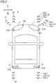
- a pair of left and right vehicle head lamps 1 of a vehicle C shown in Fig. 2 is equipped with departure notification lamps 2 each including a departure notification display device 3 (see Fig. 1 ) to be described later so as to emit light onto a road surface ahead of the vehicle.
- a pair of left and right rear combination lamps 4 corresponding to the vehicle head lamps 1 are also equipped with a pair of left and right departure notification lamps 2 each including the departure notification display device 3 so as to emit light onto a road surface at a rear side of the vehicle.
- the departure notification lamp 2 may be mounted on only one of the left and right vehicle head lamps 1 (or the rear combination lamps).
- the vehicle C may be equipped with one departure notification lamp including a vehicle front side departure notification display device and one departure notification lamp including a vehicle rear side departure notification display device at any position such as a central portion outside a vehicle body.
- the vehicle C may not include the vehicle rear side departure notification display device 3.
- a vehicle departure notification display system 33 shown in Fig. 1 is a system used for a vehicle equipped with an autonomous driving device or the like.
- the vehicle departure notification display system 33 includes the departure notification display device 3, a brake sensor 7, a start switch sensor 8, a shift sensor 9, a steering angle sensor 10, a speed sensor 11, a car navigation system 12, an imaging unit 13, a radar sensor 14, an automatic toll collection terminal 15, a turn signal lamp sensor 16, and a road information communication system 130.
- the departure notification display system 33 is mounted on the vehicle C excluding a road monitoring camera 13b of the imaging unit 13 to be described later.
- the departure notification display device 3 includes a control unit 5 and a road surface rendering unit 6.
- the control unit 5 is implemented by an arithmetic control unit such as a CPU.
- the control unit 5 determines whether a departure notification display is necessary during departure of the vehicle C based on various kinds of information detected by the brake sensor 7, the start switch sensor 8, the shift sensor 9, the steering angle sensor 10, the speed sensor 11, the car navigation system 12, the imaging unit 13, the road information communication system 130, the radar sensor 14, the automatic toll collection terminal 15, and the turn signal lamp sensor 16. The various kinds of information will be described later.
- the control unit 5 determines that a departure notification display is necessary during departure of the vehicle C, the control unit 5 controls the road surface rendering unit 6 to render a departure notification display.
- control unit 5 determines that the departure notification display is unnecessary during departure of the vehicle C
- the control unit 5 controls the road surface rendering unit 6 not to render a departure notification display. Further, the control unit 5 controls the road surface rendering unit 6 again to stop a departure notification display in a notification stop determination for determining a notification stop condition for the rendered departure notification display.
- the road surface rendering unit 6 will be described with reference to Figs. 1 and 3 .
- the road surface rendering unit 6 includes a light source 18 and a light deflection device 19.
- the road surface rendering unit 6 constitutes a part of a road surface rendering unit 17 (see Fig. 3 ).
- the road surface rendering unit 17 includes a unit body 17a, the light source 18, the light deflection device 19, a reflective optical member 20 such as a reflector, a projection optical member 21 such as a plano-convex lens, and a light absorption member 22.
- the road surface rendering unit 17 further includes the departure notification lamp 2 disposed in a housing S that is internally formed with a lamp body 2a having an opening at a front side of the vehicle and a transparent or translucent front cover 2b that closes the opening.
- the road surface rendering unit 17 is held in a manner in which the road surface rendering unit 17 can horizontally rotate inside the lamp body 2a, and is configured to swing around a central axis L1 by a motor 23 or the like.
- the road surface rendering unit 17 tilts to the left or the right under the control of the control unit 5 in Fig.
- the light source 18 examples include a semiconductor light emitting element such as a light emitting diode (LED), a laser diode (LD), and an electro luminescence (EL) element, a lamp bulb, an incandescent lamp (halogen lamp), and discharge (discharge lamp).
- a semiconductor light emitting element such as a light emitting diode (LED), a laser diode (LD), and an electro luminescence (EL) element
- EL electro luminescence
- lamp bulb a lamp bulb
- halogen lamp halogen lamp
- discharge lamp discharge lamp
- the light source 18 may emit white light, yellow light, or the like to a front side, and emit red light or the like to a rear side.
- the reflective optical member 20 reflects light emitted from the light source 18 toward the light deflection device 19.
- the light deflection device 19 is disposed on an optical axis of the projection optical member 21.
- the light deflection device 19 selectively reflects the reflected light from the reflective optical member 20 to the projection optical member 21, and emits the reflected light to the outside of the departure notification lamp 2.
- Light emitted from the departure notification lamp 2 of the vehicle head lamp 1 is used to display a vehicle departure notification display to be described later in a range from a front side to an obliquely front side of the vehicle C based on a horizontal swing of the road surface rendering unit 17.
- Light emitted from the departure notification lamp 2 of the rear combination lamp 4 is used to display a vehicle departure notification display to be described later in a range from a rear side to an obliquely rear side of the vehicle C based on a horizontal swing of the road surface rendering unit 17.
- a digital mirror device that is a micro-mirror device can be used as the light deflection device 19 according to the present embodiment shown in Figs. 1 , 3 , 4A , and 4B .
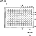
- the light deflection device 19 includes a micro-mirror array 25 in which a plurality of minute mirror elements 24 each having a reflective surface 24a on a surface of the mirror element 24 are arranged in a matrix.
- the light deflection device 19 includes a transparent cover member 26 disposed at a light emitting side of the reflective surface 24a of each of the mirror elements 24.
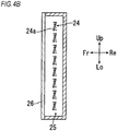
- Each of the mirror elements 24 in the micro-mirror array 25 can be switched between an ON state (a solid line position shown in Fig. 4B ) in which light emitted from the light source 18 is emitted toward the projection optical member 21 so that the light can be used as a desired light distribution pattern and an OFF state (a broken line position shown in Fig. 4B ) in which light emitted from the light source 18 is reflected by the light absorption member 22 so that the light cannot be effectively used.
- each of the mirror elements 24 can be switched between the ON state and the OFF state around a rotation axis.
- Each mirror element 24 emits a part of the emitted light to the projection optical member 21, and reflects the other emitted light to the light absorption member 22, so that the other emitted light cannot be effectively used.
- the micro-mirror array 25 can obtain a light distribution pattern or the like corresponding to a desired projection image by independently controlling the ON and OFF states of the plurality of mirror elements 24 arranged in a matrix.
- the micro-mirror array 25 shown in Figs. 4A and 4B represents brightness and darkness of light in a stepwise manner and represents reflective light of white light in monochrome by adjusting an ON time ratio when switching the ON and OFF states of each mirror element 24 at a high speed.
- reflective light from each mirror element 24 is represented to light of a desired color
- light source units of three or more colors such as red, green, and blue in the light source 18 are used to emit light to the light deflection device 19 in a time division manner, and the ON and OFF states of the mirror element are switched in a division of thousands times per second, so that a person seeing the reflective light recognizes the reflective light as mixed light due to an illusion (afterimage effect) of human eyes.
- the minute mirror elements 24 can represent various colors having predetermined brightness and darkness. Then, the light deflection device 19 can render a mark of a desired form, that is, a departure notification display onto a road surface by a set of light spots.
- the set of light spots has a predetermined brightness and color and is emitted in a matrix by the plurality of mirror elements 24 that are independently controlled.
- the light deflection device 19 may adopt a scanning mechanism for reflecting light from a light source by a reflector that is swingable in a two-dimensional direction at high speed and scans a road surface with the reflected light in a two-dimensional direction at high speed to render a mark of a desired form onto the road surface.
- the light deflection device 19 may widely adopt a rotary scanner, a Galvano scanner, a resonant scanner, an optical micro electro mechanical systems (MEMS) scanner, a polygon mirror, and the like.
- the road surface rendering unit 6 may be configured to render only one type of departure notification display onto a road surface when light passes through a predetermined optical member.
- the departure notification lamp 2 including the road surface rendering unit 6 arranges departure notification displays 27 each including a plurality of boomerang marks 27a to 27c so as to render a departure notification display.
- a corner of each of the marks 27a to 27c is oriented in a traveling direction of the vehicle as shown in Fig. 2 .
- the number of the plurality of marks is not limited to three as long as a plurality of marks are rendered, and a shape of each mark is not limited to a boomerang. It is desirable that the departure notification display 27 is rendered in order from a mark close to the vehicle in which the mark 27a is turned on or turned off, then the mark 27b is turned on or turned off, and finally, the mark 27c is turned on or off.
- the departure notification display 27 is rendered as if the mark 27a gradually advances to positions of the mark 27b and the mark 27c along a traveling direction of the vehicle, a pedestrian or the like who sees the departure notification display 27 can recognize a departure direction of the vehicle simply by confirming the departure notification display 27 is displayed in which direction of the vehicle C.
- a pedestrian or the like sees the departure notification display 27 as if the mark 27a advances to the positions of the mark 27b and the mark 27c, the pedestrian or the like can recognize a departure direction of the vehicle.
- the brake sensor 7 of the vehicle departure notification display system 33 shown in Fig. 1 functions as a brake detection unit that detects switching information between ON (braking state) and OFF (releasing state) of a foot brake of the vehicle C.
- a brake detected by the brake sensor 7 is not limited to a foot brake, and may be a hand brake or an automatic brake that is automatically controlled by a system of an automatic driving vehicle and does not involve an operation from a driver as long as the brake is used to stop a vehicle in traveling based on a closing degree and then the brake is released at a predetermined opening degree.
- the brake sensor 7 detects releasing of the foot brake of the vehicle C that was in a braking state, and outputs the switching information to the control unit 5.
- the start switch sensor 8 in Fig. 1 functions as a brake detection unit that detects switching information between OFF and ON of a start switch (an ignition switch, a keyless system start switch, and the like) of the vehicle C.
- the start switch sensor 8 detects switching information indicating that the start switch is switched from OFF to ON, and outputs the switching information to the control unit 5.
- the shift sensor 9 is a shift detection unit that detects information indicating whether a shift lever of the vehicle C is at forward (D position: drive), reverse (R position: reverse), parking (P position), or the like.
- D position drive
- R position reverse
- P position parking
- the shift sensor 9 detects information related to a forward movement of the vehicle C and outputs the information to the control unit 5.
- the shift sensor 9 detects information related to a reverse movement of the vehicle C and outputs the information to the control unit 5.
- the steering angle sensor 10 functions as a steering detection unit that detects information related to any one of straight traveling, a right steering, and a left steering of the vehicle C. For example, when a steering device (steering wheel or the like, not shown) during straight traveling of the vehicle C is steered in a right turn direction from a steering angle of 0°, a steering angle is set as a plus angle, and when the steering device is steered in a left turn direction, a steering angle is set as a minus angle.
- the steering angle sensor 10 detects the plus steering angle as information related to a right steering of the vehicle C, or detects the minus steering angle as information related to a left steering of the vehicle C, and outputs the information to the control unit 5.
- the speed sensor 11 functions as a temporary stop detection unit that detects information related to a temporary stop of the vehicle based on a speed change of the vehicle, and outputs the information to the control unit 5. Specifically, the speed sensor 11 detects a speed of the vehicle at regular time intervals. When the speed sensor 11 detects information indicating that a vehicle speed is zero after either information related to a positive vehicle speed (forward) or information related to a negative vehicle speed (reverse) is detected, the speed sensor 11 detects information related to a temporary stop of the vehicle and outputs the information to the control unit 5. The speed sensor 11 can also be used in a departure notification display stop determination executed by the control unit 5.
- the car navigation system 12 functions as a necessary target detection unit that detects a necessary target for a vehicle departure notification display or an unnecessary target detection unit that detects an unnecessary target for a vehicle departure notification display based on road information that is stored in the car navigation system 12 or is transmitted via a communication line and position information of the own vehicle obtained by a satellite positioning system such as a global navigation satellite system (GNSS) and a global positioning system (GPS, registered trademark).
- GNSS global navigation satellite system
- GPS global positioning system
- the necessary target for a vehicle departure notification display detected by the car navigation system 12 is whether there is an obligation to temporarily stop the vehicle C at intersecting roads where the vehicle C arrived, a T-shaped road, and an entrance to a priority road (from a narrow road to a wide road) at an intersection.
- the unnecessary target for a vehicle departure notification display is a "traffic jam" where the vehicle C arrived, an expressway toll station, a railroad crossing, and the like.
- the imaging unit 13 includes an in-vehicle camera 13a, the road monitoring camera 13b, and an image processing device 13c.
- the imaging unit 13 functions as the necessary target detection unit that detects a necessary target for a vehicle departure notification display or the unnecessary target detection unit that detects an unnecessary target for the vehicle departure notification display, based on an image obtained by imaging surroundings of the vehicle C.
- the in-vehicle camera 13a may be incorporated in the vehicle head lamps 1 so that front surroundings of the vehicle C can be imaged as shown in Fig. 2 .
- the in-vehicle camera 13a may be mounted at a position where a top surface of a ceiling of a vehicle body, a hood, a door mirror, and the like or surroundings of the vehicle C can be imaged, or may be mounted on the rear combination lamps 4 so that rear surroundings of the vehicle C can be imaged.
- the in-vehicle camera 13a images surroundings of the vehicle C on which the in-vehicle camera 13a is mounted.
- the road monitoring camera 13b may be installed on a road.
- the road monitoring camera 13b images surroundings of the vehicle C coming close to the road monitoring camera 13b.
- the image processing device 13c may be mounted on the vehicle C.
- the image processing device 13c detects a necessary target or an unnecessary target for a vehicle departure notification display by analyzing an image captured by the in-vehicle camera 13a or an image that is captured by the road monitoring camera 13b and transmitted to the image processing device 13c via a communication line, and the imaging processing device 13c outputs the necessary target or the unnecessary target for a vehicle departure notification display to the control unit 5.
- the necessary target for a vehicle departure notification display detected by the imaging unit 13 is a sign indicating an obligation to temporarily stop the vehicle C at intersecting roads, a T-shaped road, an entrance to a priority road (from a narrow road to a wide road) at an intersection, a pedestrian waiting to cross a road, and the like that are imaged by the in-vehicle camera 13a at a position where the vehicle C arrived.
- the necessary target for a vehicle departure notification display detected by the imaging unit 13 is a road with a sign indicating an obligation to temporarily stop the vehicle C, a T-shaped road, an entrance to a priority road (from a narrow road to a wide road) at an intersection, a pedestrian waiting to cross a road, and the like that are imaged by the road monitoring camera 13b.
- the unnecessary target for a vehicle departure notification display detected by the imaging unit 13 is a "traffic jam", an expressway toll station, a railroad crossing, and the like that are imaged by the in-vehicle camera 13a, or a "traffic jam", an "expressway toll station", a "railroad crossing”, and the like that are imaged by the road monitoring camera 13b.
- the necessary target detection unit and the unnecessary target detection unit may include a radar sensor using a millimeter wave radar, a laser imaging detection and ranging (LiDAR), ultrasonic waves, and the like.
- the road information communication system 130 functions as the unnecessary target detection unit (a stop signal detection unit when a stop signal is detected) that detects traffic jam information at a current position of the own vehicle linked with position information of the vehicle C obtained by the satellite positioning system of the car navigation system 12 and stop signal (red light signal) information of traffic lights at an intersection where the own vehicle is about to arrive, as an unnecessary target for a departure notification display.
- the road information communication system 130 is vehicle information and communication system (VICS, registered trademark) or the like.
- the road information communication system 130 detects information related to a traffic jam or a stop signal (red light signal) that is an unnecessary target, and outputs the information to the control unit 5.
- the radar sensor 14 is a microwave radar sensor, a millimeter wave radar sensor, or the like.
- the radar sensor 14 functions as a preceding vehicle detection unit that detects a preceding vehicle of the own vehicle as an unnecessary target for the vehicle departure notification display.
- the radar sensor 14 detects information related to the preceding vehicle, and outputs the information to the control unit 5.
- the automatic toll collection terminal 15 is an in-vehicle device such as an electronic toll collection system (ETC, registered trademark) that automatically pays a toll when the own vehicle passes through an automatic toll collection device 32 (see Fig. 8 ) installed at an expressway toll station or the like.
- the automatic toll collection terminal 15 wirelessly communicates with the automatic toll collection device (not shown) installed at the toll station.
- the automatic toll collection terminal 15 functions as an automatic toll collection device detection unit that detects a fact that the own vehicle passes through the automatic toll collection device 32 as an unnecessary target for a vehicle departure notification display, and outputs information indicating that the own vehicle passed through the automatic toll collection device to the control unit 5.
- the turn signal lamp sensor 16 functions as a turn signal lamp detection unit that detects switching information indicating that a turn signal lamp is switched from OFF to ON as an unnecessary target for a vehicle departure notification display, and outputs the switching information indicating that the turn signal lamp is switched from OFF to ON to the control unit 5.
- a departure notification display for the vehicle C that departs forward or rearward from a parking state will be described with reference to Fig. 5 .
- a departure notification display device 3a indicates a left front side departure notification display device 3
- a departure notification display device 3b indicates a right front side departure notification display device 3.
- Departure notification displays rendered by the left and right front side departure notification display devices 3a and 3b are denoted by 271 (left front side) and 272 (right front side).
- a departure notification display device 3 that is mounted on the left and right rear combination lamps 4 and renders a departure notification display onto a road surface at a rear side of the vehicle
- a departure notification display device 3c indicates a left rear side departure notification display device 3
- a departure notification display device 3d indicates a right rear side departure notification display device 3.
- Departure notification displays rendered by the left and right rear side departure notification display devices 3c and 3d are denoted by 273 (left rear side) and 274 (right rear side).
- a driver of the vehicle C in Fig. 5 turns on a start switch or the like of the vehicle C in a braking state (an ON state of a brake) in which a foot brake pedal is stepped on.
- the driver shifts a shift lever of the vehicle C to forward (drive) or reverse, and releases the foot brake that was stepped on (an OFF state of the brake).
- the start switch sensor 8 detects switching information indicating that the start switch is switched from OFF to ON, and outputs the switching information to the control unit 5. Subsequently, the brake sensor 7 detects switching information indicating that the brake is switched from ON (braking) to OFF (releasing), and outputs the switching information to the control unit 5.
- the control unit 5 executes a necessity determination for determining whether a departure notification display is necessary based on the switching information described above. Further, the control unit 5 determines a traveling direction of the vehicle based on information related to a position of the shift lever detected by the shift sensor 9, and determines a display direction of a departure notification display.
- the control unit 5 controls the road surface rendering unit 6 to render the departure notification displays 271 and 272 onto a road surface ahead of the vehicle.
- the driver of the vehicle C calls attention of a pedestrian H1 or the like who wants to cross a front side of the vehicle C that "the vehicle C in park is about to depart forward from now on”.
- the control unit 5 controls the road surface rendering unit 6 to render the departure notification displays 273 and 274 onto a road surface at the rear side of the vehicle C in a releasing state of the brake pedal.
- the driver of the vehicle C calls attention of a pedestrian or the like (not shown) who wants to cross a rear side of the vehicle C that "the vehicle C in park is about to reverse from now on”. Accordingly, a pedestrian or the like can accurately know departure timing of the vehicle C.
- ON and OFF switching of the start switch may not be included in a determination condition. In this case, a departure notification display is rendered even when the vehicle is temporarily stopped under a situation in which the departure notification display is unnecessary (signal waiting or the like). Therefore, it is desirable to restrict the departure notification display by limiting a necessity determination condition.
- the control unit 5 of the departure notification display device 3 controls the road surface rendering unit 6 again to stop rendering a departure notification display onto a road surface when the speed sensor 11 detects information indicating the vehicle speed of the vehicle C that is detected at regular time intervals is accelerated from zero to a predetermined speed or more (for example, the speed is 5 Km/h or more.
- the speed is not limited thereto.)
- a total distance meter or the like (not shown) provided in the vehicle C detects information indicating that the vehicle C travels for a predetermined distance since the vehicle C starts to travel (for example, the vehicle C travels for 10 m since the vehicle C starts to travel.
- the distance is not limited thereto.
- a timer (not shown) provided in the vehicle C detects information indicating that the vehicle C travels for a predetermined period of time since the vehicle starts to travel (for example, the vehicle C travels for 10 seconds since the vehicle C starts to travel.
- the period of time is not limited thereto)
- the steering angle sensor 10 or the turn signal lamp sensor 16 detects information indicating that a left steering or a right steering of the vehicle C is completed (that is, when the steering angle sensor 10 detects information indicating that a detected angle of the steering device is returned to an angle of zero from either a plus angle or a minus angle, or when the turn signal lamp sensor 16 detects information indicating that a turn signal switch is switched from ON to OFF).
- the control unit 5 controls the road surface rendering unit 6 so as to render a departure notification display for a long period of time by changing the predetermined values described above (for example, changing a speed related to a stop from 5 Km/h or more to 10 Km/h or more, changing a distance from 10 m to 15 m, changing a period time from 10 seconds to 15 seconds, and the like) in order to call sufficient attention of the detected pedestrian or the like that the vehicle is about to depart. It is desirable that the control unit 5 executes the same control in the second embodiment to the fifth embodiment to be described later.
- the departure notification display device 3 of the vehicle C determines that a condition in which the start switch is switched to ON before the brake pedal is switched to a releasing state is a determination condition necessary for a departure notification display, an unnecessary departure notification display is not displayed when a departure notification display is unnecessary, such as when the vehicle departs from a temporary stop due to a red light signal or a railroad crossing in the first embodiment.
- the vehicle departure notification display device 3 having the configuration described above, since a departure notification display is displayed only immediately before departure of a vehicle, a pedestrian or the like can recognize the departure notification display and can accurately know departure timing of the vehicle C.
- a departure notification display is displayed immediately before departure of a parked vehicle, but is not displayed immediately before departure of a vehicle when the vehicle departs from a temporary stop state. Therefore, there is no need to render an unnecessary departure notification display for departure from a traffic jam, departure from signal waiting, and departure from a temporary stop in which it is unnecessary to notify a pedestrian or the like of departure of a vehicle.
- a departure notification display is rendered onto a road surface ahead of the vehicle C when the parked vehicle moves forward.
- a departure notification display is rendered onto a road surface at a rear side of the vehicle C when the parked vehicle reverses. In this manner, a pedestrian or the like can accurately know a departure direction of the vehicle C.
- a driver of the vehicle C in Fig. 6A turns on a start switch or the like of the vehicle C in a braking state (an ON state of a brake) in which a foot brake pedal is stepped on.
- the driver shifts a shift lever of the vehicle C to forward (drive), steers a steering wheel (a steering device (not shown)) to the left or the right, and releases the foot brake that was stepped on (an OFF state of the brake).
- the start switch sensor 8 detects switching information indicating that the start switch is switched from OFF to ON, and outputs the switching information to the control unit 5. Subsequently, the brake sensor 7 detects switching information indicating that the brake is switched from ON (braking) to OFF (releasing), and outputs the switching information to the control unit 5.
- the control unit 5 executes a necessity determination for determining whether a departure notification display is necessary based on the switching information described above. Further, the shift sensor 9 detects information indicating that the shift lever is at the drive position (forward), and outputs the information to the control unit 5.
- the steering angle sensor 10 detects information related to a left or right steering direction of the vehicle, and outputs the information to the control unit 5. The control unit 5 determines a display direction of the departure notification display based on the information described above.
- the control unit 5 of the departure notification display device 3b controls the road surface rendering unit 6 to render the departure notification display 272 onto a road surface ahead of the vehicle obliquely to the right.
- the driver of the vehicle C calls attention of a pedestrian H2 or the like who wants to pass through a right side of the vehicle C in parallel parking that "the vehicle C in parallel parking is about to depart to a right front side from now on” in a country where a vehicle travels at a left side.
- the control unit 5 of the departure notification display device 3a controls the road surface rendering unit 6 to render the departure notification display 271 on a road surface ahead of the vehicle C obliquely to the left.
- the driver of the vehicle C calls attention of a pedestrian H3 or the like who wants to pass through a left side of the vehicle C in parallel parking that "the vehicle C in parallel parking is about to depart to a left front side from now on” in a country where a vehicle travels at a right side.
- the departure notification displays 271 and 272 displayed at a front side obliquely to the left and a front side obliquely to the right may be displayed in a lateral direction to the left or the right instead of an oblique direction when a vehicle in parallel parking departs to a directly lateral side in future automatic driving or the like.
- the vehicle departure notification displays 271 and 272 are rendered at a front side obliquely to the right or at a front side obliquely to the left corresponding to a steering direction.
- the vehicle C may depart to an obliquely rear side.
- the vehicle departure notification display devices 3 provided in the rear combination lamps 4 cause the road surface rendering unit 17 to swing, and the road surface rendering unit 6 may display the departure notification displays 273 and 274 (see Fig. 5 ) at a rear side obliquely to the left or at a rear side obliquely to the right corresponding to a left or right steering direction of rear wheels.
- the vehicle departure notification display device 3 having the configuration described above, when a parked vehicle departs from a parallel parking state or the like to a left or right direction, a pedestrian or the like can accurately know a left or right direction in which the vehicle C departs.
- the speed sensor 11 detects information indicating that a vehicle speed of the own vehicle is decelerated to zero from a positive speed by a foot brake operation from the driver, and outputs the information to the control unit 5.
- the control unit 5 recognizes a temporary stop of the vehicle C based on the information. After the vehicle C is temporarily stopped, when the driver releases the foot brake that was stepped on after a predetermined period of time (for example, after one minute since the vehicle C is temporarily stopped.
- the brake sensor 7 detects information indicating that the foot brake is released.
- the steering angle sensor 10 detects information indicating that the steering wheel is steered to a right side (or a left steering), and outputs the information to the control unit 5.
- the control unit 5 controls the road surface rendering unit 6 of the departure notification display device 3b (the departure notification display device 3a in case of a left steering) to render the departure notification display 272 onto a road surface ahead of the vehicle C obliquely to the right (render the departure notification display 271 onto a road surface ahead of the vehicle C obliquely to the left in case of a left steering).
- the control unit 5 executes an unnecessary determination for a departure notification display for determining whether information related to ON and OFF of the foot brake detected after a predetermined period of time since the vehicle C is temporarily stopped is information detected based on a temporarily stop in which a departure notification display is unnecessary, such as signal waiting.
- the control unit 5 determines that the departure notification display is unnecessary, the control unit 5 controls the road surface rendering unit 6 not to render a departure notification display.
- a pedestrian or the like can accurately know departure time of a temporarily stopped vehicle when the vehicle departs from a lateral parking.
- a vehicle is temporarily stopped for a short period of time and then departs, such as when the vehicle departs from signal waiting, there is no need to let a pedestrian or the like know departure of the vehicle, and there is no need to render an unnecessary departure notification display.
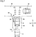
- the car navigation system 12 or the imaging unit 13 detects whether there is an obligation to temporarily stop the vehicle C at intersecting roads where the vehicle C arrived (detected by the car navigation system 12 only), a temporary stop obligation sign 28 installed at intersecting roads where the vehicle C arrived or a temporary stop mark (not shown) on a road surface (detected by the imaging unit 13 only), a T-shaped road with no traffic lights where the vehicle C arrived, an entrance (entrance to a wide road from a narrow road) to a priority road at intersecting roads where the vehicle C arrived, a pedestrian H4 waiting to cross a road and a vehicle C3 that is about to pass through intersecting roads (detected by the imaging unit 13 only), and the like.
- the car navigation system 12 or the imaging unit 13 outputs the detected information to the control unit 5.
- the brake sensor 7 detects switching information from a temporary stop in which the driver steps on the foot brake (an ON state of the brake) to releasing of the foot brake (an OFF state of the brake), and outputs the switching information to the control unit 5.
- the control unit 5 executes a necessity determination for a departure notification display based on the information output from the car navigation system 12 or the imaging unit 13 and the switching information output from the brake sensor 7.
- the control unit 5 controls the road surface rendering unit 6 of the departure notification display devices 3a and 3b to render the departure notification displays 271 and 272 onto a road surface of a road R2 that is located ahead of the vehicle C and intersects a road R1 on which the own vehicle travels.
- the driver of the vehicle C calls attention of the pedestrian H4 who is about to cross the road R1 and pass through a front side of the vehicle C, the vehicle C3 that travels on the road intersecting the road R1, or the like that "the temporarily stopped vehicle C is about to enter the ahead road intersecting the road R1 from now on”.
- the departure notification displays 271 and 272 are not displayed until the driver of the vehicle C releases the brake pedal that was stepped on. Therefore, when the driver of the vehicle C waits for the pedestrian H4 waiting to cross the road 1 and the pedestrian H4 walks on the road 1 but does not pass through a front side of the vehicle C yet, the pedestrian H4 can accurately know that the vehicle does not start moving based on a fact that the departure notification display is not rendered. As a result, the pedestrian H4 can cross the road and pass through the front side of the vehicle C at ease.
- the in-vehicle camera 13a detects the pedestrians H1 to H4 or the vehicles C2 and C3 that are present in a vehicle traveling direction before the driver releases the foot brake that was stepped on, the control unit 5 executes the necessity determination and displays the departure notification display in the traveling direction of the vehicle C.
- the control unit 5 may execute an unnecessary determination for a departure notification display and control the road surface rendering unit 6 not to render a departure notification display.
- the departure notification display device 3 having the configuration described above, when the departure notification display device 3 detects a temporary stop sign, a T-shaped road, a pedestrian waiting to cross a road, and the like as a necessary target for a departure notification display, since the departure notification display is displayed at the time when the vehicle departs from a temporary stop, the pedestrian or the like can accurately know departure timing of the vehicle.
- a departure notification display is not displayed based on a fact that an unnecessary target is detected when the vehicle C is temporarily stopped according to a fifth embodiment
- the car navigation system 12, the imaging unit 13, the radar sensor 14, the automatic toll collection terminal 15, and the turn signal lamp sensor 16 shown in Fig. 1 function as an unnecessary target detection unit that detects an unnecessary target for a departure notification display.
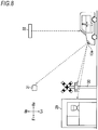
- the unnecessary target for a departure notification display is a traffic jam (not shown) detected at a position where the vehicle C arrived, an expressway toll station 29 and a railroad crossing 30 shown in Fig. 8 , that are detected by the car navigation system 12. Further, the unnecessary target for a departure notification display is the expressway toll station 29, the railroad crossing 30, and a stop signal (red light signal) 31 that are detected based on an image obtained by the in-vehicle camera 13a of the imaging unit 13 imaging a position where the vehicle C arrived.
- the unnecessary target for a departure notification display may be a traffic jam or the stop signal (red light signal) 31 detected by a road information communication system at a position where the vehicle C arrived.
- the unnecessary target for a departure notification display may be a preceding vehicle (not shown) that travels ahead of the vehicle C and is detected by the radar sensor 14, the automatic toll collection device 32 detected by the automatic toll collection terminal 15 at an expressway toll station or the like where the vehicle C arrived, waiting for a right turn or a left turn detected by the turn signal lamp sensor 16.
- the control unit 5 executes an unnecessary determination for a departure notification display based on the switching information output from the brake sensor 7. Even when the vehicle is temporarily stopped by the driver stepping on the foot brake and then the foot brake is released, the control unit 5 controls the road surface rendering unit 6 not to render a departure notification display based on a fact that the unnecessary target detection unit detects an unnecessary target for a departure notification display.
- the departure notification display device 3 does not need to display an unnecessary departure notification display when the vehicle departs from a temporary stop due to signal waiting and the like, and when a pedestrian, another vehicle, or the like in the traveling direction can easily know departure timing of the vehicle C even if a departure notification display is not rendered onto a road surface.
- the departure notification display device 3 does not need to display an unnecessary departure notification display when an unnecessary target for a departure notification display, such as signal waiting, a traffic jam, passing through an expressway toll station or an automatic toll collection device, a railroad crossing, and waiting for a left or right turn at an intersection, is detected.
- an unnecessary target for a departure notification display such as signal waiting, a traffic jam, passing through an expressway toll station or an automatic toll collection device, a railroad crossing, and waiting for a left or right turn at an intersection.
- Fig. 9 is a block diagram showing the departure notification display device 3A according to a modification.
- the departure notification display device 3A mounted on the vehicle C includes the control unit 5, the road surface rendering unit 6, the brake sensor 7, the start switch sensor 8, the shift sensor 9, the steering angle sensor 10, the speed sensor 11, the car navigation system 12, the imaging unit 13A, the radar sensor 14, the automatic toll collection terminal 15, the turn signal lamp sensor 16, and the road information communication system 130.
- the imaging unit 13A includes the in-vehicle camera 13a and the image processing device 13c and does not include the road monitoring camera 13b.
- the imaging unit 13A is different from the imaging unit 13 in terms of this point.
- the road monitoring camera 13b is installed outside the vehicle C.
- a vehicle to which the departure notification display device 3A according to the modification is applied also has effects the same as the vehicle C to which the departure notification display system 33 is applied as described above. That is, the above-described effects can be achieved by the departure notification display device 3A.
Landscapes
- Engineering & Computer Science (AREA)
- Mechanical Engineering (AREA)
- Automation & Control Theory (AREA)
- Transportation (AREA)
- General Engineering & Computer Science (AREA)
- Lighting Device Outwards From Vehicle And Optical Signal (AREA)
- Traffic Control Systems (AREA)
Abstract
Description
- The present invention relates to a departure notification display device that notifies a pedestrian or the like of departure of a vehicle.
-
Patent Literature 1 discloses a vehicle departure safety control device that notifies a pedestrian or the like of departure of a vehicle by projecting laser light of a predetermined pattern onto a road surface accompanying with departure of a parked vehicle.
Patent Literature 1:JP 2016-101797 A - The vehicle departure safety control device disclosed in
Patent Literature 1 renders a predetermined departure notification pattern onto a road surface to notify a pedestrian or the like of departure of a vehicle in parking, that is, in a state in which a speed is zero. Therefore, the departure notification pattern is continuously displayed on the road surface even when the parked vehicle does not depart immediately after the departure notification pattern is displayed. Therefore, a pedestrian, another traveling vehicle, or the like (hereinafter, simply referred to as a pedestrian or the like) that sees the departure notification pattern may not be able to accurately know departure timing of the vehicle. - An object of the present disclosure is to provide a vehicle departure notification display device having an effect that a pedestrian or the like who sees a departure notification display rendered onto a road surface from a vehicle can accurately know departure timing of the vehicle.
- In order to achieve the object described above, according to an aspect of the present disclosure, there is provided a vehicle departure notification display device. The vehicle departure notification display device includes a road surface rendering unit mounted on a vehicle and configured to render a departure notification display having a predetermined shape onto a road surface in a traveling direction of the vehicle by light, and a control unit configured to determine whether a departure notification display is necessary in departure of the vehicle and configured to control the road surface rendering unit to render a departure notification display in a necessity determination and control the road surface rendering unit again to stop a departure notification display in a notification stop determination for the rendered departure notification display. The control unit regards detection of switching information indicating that a brake of the vehicle is switched from ON to OFF as the necessity determination for the departure notification display and controls the road surface rendering unit to render a departure notification display.
- According to the above configuration, the control unit controls the road surface rendering unit to render a vehicle departure notification display onto the road surface accompanying with releasing of the brake right before departure of the vehicle, and controls the road surface rendering unit to stop rendering the departure notification display according to a rendering stop determination.
- In the vehicle departure notification display device according to another aspect of the present disclosure, the control unit may regard the detection of the switching information indicating that the brake is switched from ON to OFF after detection of switching information indicating that the start switch of the vehicle is switched from OFF to ON as the necessity determination and controls the road surface rendering unit to render a departure notification display.
- According to the above configuration, the road surface rendering unit renders a vehicle departure notification display of a parked vehicle onto the road surface based on information indicating that the start switch is turned on when the vehicle departs from a parked state and switching information indicating that the brake is switched from a braking state to a releasing state after the start switch is turned on.
- In the vehicle departure notification display device according to still another aspect of the present disclosure, the control unit may be configured to control the road surface rendering unit to render the departure notification display in a front direction of the vehicle when information related to a forward movement of the vehicle is detected and control the road surface rendering unit to render the departure notification display in a rear direction of the vehicle when information related to a reverse movement of the vehicle is detected.
- According to the above configuration, the road surface rendering unit renders a departure notification display in a front direction of the vehicle when the information related to a forward movement of the vehicle (a shift lever is at a drive "D" position) is detected. The road surface rendering unit renders a departure notification display in a rear direction of the vehicle when the information related to a reverse movement of the vehicle (the shift lever is at a reverse "R" position) is detected.
- In the vehicle departure notification display device according to still another aspect of the present disclosure, the control unit may be configured to control the road surface rendering unit to render a departure notification display in a right direction of the vehicle when information related to a right steering of the vehicle is detected and control the road surface rendering unit to render a departure notification display in a left direction of the vehicle when information related to a left steering of the vehicle is detected.
- According to the above configuration, the road surface rendering unit renders a departure notification display in a right direction of the vehicle when information related to a right steering of the vehicle is detected. The road surface rendering unit renders a departure notification display in a left direction of the vehicle when information related to a left steering of the vehicle is detected.
- In the vehicle departure notification display device according to still another aspect of the present disclosure, the control unit may regard detection of information related to a temporary stop of the vehicle and detection of switching information indicating that the brake is switched from ON to OFF is detected after a period of non-notification determination from the detection of the information related to the temporary stop as the necessity determination for a departure notification display and control the road surface rendering unit to render a departure notification display.
- According to the above configuration, when switching information indicating that the brake is switched from a braking state to a releasing state is detected after a period of non-notification determination since information related to a temporary stop of the vehicle is detected, the road surface rendering unit renders a vehicle departure notification display onto a road surface.
- In the vehicle departure notification display device according to still another aspect of the present disclosure, the control unit may regard the detection of the switching information indicating that the brake is switched from ON to OFF after detection of a necessary target detected by a detection unit configured to detect the necessary target for a departure notification display as the necessity determination for a departure notification display and control the road surface rendering unit to render a departure notification display.
- According to the above configuration, when switching information indicating that the brake is switched from a braking state to a releasing state is detected after a necessary target for a departure notification display is detected, the road surface rendering unit renders a vehicle departure notification display onto a road surface.
- In the vehicle departure notification display device according to still another aspect of the present disclosure, the necessary target detection unit may be a car navigation system, and the necessary target may be detected based on road information obtained by the car navigation system.
- In the vehicle departure notification display device according to still another aspect of the present disclosure, the necessary target detection unit may be an imaging unit that images surroundings of the vehicle, and the necessary target may be detected based on an image captured by the imaging unit.
- In the vehicle departure notification display device according to still another aspect of the present disclosure, the control unit may regard the detection of the switching information indicating that the brake is switched from ON to OFF after detection of an unnecessary target detected by an unnecessary target detection unit configured to detect an unnecessary target for a departure notification display as an unnecessary determination for a departure notification display and control the road surface rendering unit not to render a departure notification display.
- According to the above configuration, when the brake is switched from a braking state to a releasing state after an unnecessary target for a departure notification display is detected, the road surface rendering unit does not render a vehicle departure notification display onto a road surface.
- In the vehicle departure notification display device according to still another aspect of the present disclosure, the unnecessary target detection unit may be a car navigation system, and the unnecessary target may be detected based on road information obtained by the car navigation system.
- In the vehicle departure notification display device according to still another aspect of the present disclosure, the unnecessary target detection unit may be an imaging unit that images surroundings of the vehicle, and the unnecessary target may be detected based on an image captured by the imaging unit.
- In the vehicle departure notification display device according to still another aspect of the present disclosure, the unnecessary target detection unit may be a stop signal detection unit that detects a stop signal of the vehicle as the unnecessary target.
- In the vehicle departure notification display device according to still another aspect of the present disclosure, the unnecessary target detection unit may be a preceding vehicle detection unit that detects a preceding vehicle of the vehicle as the unnecessary target.
- In the vehicle departure notification display device according to still another aspect of the present disclosure, the unnecessary target detection unit may be an automatic toll collection device detection unit that detects a fact that the vehicle passes through an automatic toll collection device as the unnecessary target.
- In the vehicle departure notification display device according to still another aspect of the present disclosure, the unnecessary target detection unit may be a turn signal lamp detection unit that detects ON and OFF of a turn signal lamp of the vehicle as the unnecessary target.
- According to the vehicle departure notification display device described above, since the departure notification display is displayed only immediately before the departure of the vehicle, a pedestrian or the like who sees the departure notification display can accurately know departure timing of a vehicle.
-
-
Fig. 1 is a block diagram showing a vehicle departure notification display system according to an embodiment of the present disclosure. -
Fig. 2 is a plan view showing a vehicle equipped with a departure notification display device. -
Fig. 3 is a cross sectional view taken along a line I-I inFig. 2 and showing a vehicle lamp including the departure notification display device. -
Fig. 4A is a cross sectional view taken along a line II-II inFig. 3 and showing a light deflection device of a road surface rendering unit. -
Fig. 4B is a cross sectional view taken along a line III-III inFig. 4A and showing the light deflection device of the road surface rendering unit. -
Fig. 5 is a view showing a state of rendering, onto a road surface, a departure notification display from a vehicle that departs forward or rearward from a parking state according to a first embodiment. -
Fig. 6A is a view showing a state of rendering, onto a road surface, a departure notification display from a vehicle that departs forward obliquely to the left or the right from a parallel parking state according to a second embodiment. -
Fig. 6B is a view showing a state of rendering, onto a road surface, a departure notification display from a vehicle that departs to an obliquely front side from a state in which the vehicle is laterally parked adjacent to another vehicle according to a third embodiment. -
Fig. 7 is a view showing a state of rendering, onto a road surface, a departure notification display when detecting a necessary target for the departure notification display during a temporary stop according to a fourth embodiment. -
Fig. 8 is a view showing a state of not rendering, onto a road surface, a departure notification display when detecting signal waiting or the like as an unnecessary target for a notification display during a temporary stop according to a fifth embodiment. -
Fig. 9 is a block diagram showing a departure notification display device according to a modification. - Hereinafter, preferred embodiments of the present disclosure will be described with reference to the accompanying drawings. Directions shown in the drawings (upper: Up, lower: Lo, left: Le, Right: Ri, front: Fr, rear: Re) are directions viewing from a driver of a vehicle equipped with a departure notification display device or a part of a vehicle lamp including the departure notification display device. The directions are directions displayed for the convenience of description, and the present disclosure is not intended to be limited to the shown directions.
- A pair of left and right
vehicle head lamps 1 of a vehicle C shown inFig. 2 is equipped withdeparture notification lamps 2 each including a departure notification display device 3 (seeFig. 1 ) to be described later so as to emit light onto a road surface ahead of the vehicle. A pair of left and rightrear combination lamps 4 corresponding to thevehicle head lamps 1 are also equipped with a pair of left and rightdeparture notification lamps 2 each including the departurenotification display device 3 so as to emit light onto a road surface at a rear side of the vehicle. Alternatively, thedeparture notification lamp 2 may be mounted on only one of the left and right vehicle head lamps 1 (or the rear combination lamps). Alternatively, the vehicle C may be equipped with one departure notification lamp including a vehicle front side departure notification display device and one departure notification lamp including a vehicle rear side departure notification display device at any position such as a central portion outside a vehicle body. Alternatively, the vehicle C may not include the vehicle rear side departurenotification display device 3. - A vehicle departure
notification display system 33 shown inFig. 1 is a system used for a vehicle equipped with an autonomous driving device or the like. The vehicle departurenotification display system 33 includes the departurenotification display device 3, abrake sensor 7, astart switch sensor 8, ashift sensor 9, asteering angle sensor 10, aspeed sensor 11, acar navigation system 12, animaging unit 13, aradar sensor 14, an automatictoll collection terminal 15, a turnsignal lamp sensor 16, and a roadinformation communication system 130. The departurenotification display system 33 is mounted on the vehicle C excluding aroad monitoring camera 13b of theimaging unit 13 to be described later. The departurenotification display device 3 includes acontrol unit 5 and a roadsurface rendering unit 6. - The
control unit 5 is implemented by an arithmetic control unit such as a CPU. Thecontrol unit 5 determines whether a departure notification display is necessary during departure of the vehicle C based on various kinds of information detected by thebrake sensor 7, thestart switch sensor 8, theshift sensor 9, thesteering angle sensor 10, thespeed sensor 11, thecar navigation system 12, theimaging unit 13, the roadinformation communication system 130, theradar sensor 14, the automatictoll collection terminal 15, and the turnsignal lamp sensor 16. The various kinds of information will be described later. When thecontrol unit 5 determines that a departure notification display is necessary during departure of the vehicle C, thecontrol unit 5 controls the roadsurface rendering unit 6 to render a departure notification display. On the other hand, when thecontrol unit 5 determines that the departure notification display is unnecessary during departure of the vehicle C, thecontrol unit 5 controls the roadsurface rendering unit 6 not to render a departure notification display. Further, thecontrol unit 5 controls the roadsurface rendering unit 6 again to stop a departure notification display in a notification stop determination for determining a notification stop condition for the rendered departure notification display. - The road
surface rendering unit 6 will be described with reference toFigs. 1 and3 . As shown inFig. 1 , the roadsurface rendering unit 6 includes alight source 18 and alight deflection device 19. The roadsurface rendering unit 6 constitutes a part of a road surface rendering unit 17 (seeFig. 3 ). As shown inFig. 3 , the roadsurface rendering unit 17 includes aunit body 17a, thelight source 18, thelight deflection device 19, a reflectiveoptical member 20 such as a reflector, a projectionoptical member 21 such as a plano-convex lens, and alight absorption member 22. The roadsurface rendering unit 17 further includes thedeparture notification lamp 2 disposed in a housing S that is internally formed with alamp body 2a having an opening at a front side of the vehicle and a transparent or translucentfront cover 2b that closes the opening. The roadsurface rendering unit 17 is held in a manner in which the roadsurface rendering unit 17 can horizontally rotate inside thelamp body 2a, and is configured to swing around a central axis L1 by amotor 23 or the like. The roadsurface rendering unit 17 tilts to the left or the right under the control of thecontrol unit 5 inFig. 1 , and switches an emission direction of a road surface rendering display onto a road surface to a front side or an obliquely front side of the vehicle C (for the roadsurface rendering unit 17 of therear combination lamp 4, switch to a rear side or an obliquely rear side of the vehicle C). - Examples of the
light source 18 include a semiconductor light emitting element such as a light emitting diode (LED), a laser diode (LD), and an electro luminescence (EL) element, a lamp bulb, an incandescent lamp (halogen lamp), and discharge (discharge lamp). For example, thelight source 18 may emit white light, yellow light, or the like to a front side, and emit red light or the like to a rear side. - The reflective
optical member 20 reflects light emitted from thelight source 18 toward thelight deflection device 19. Thelight deflection device 19 is disposed on an optical axis of the projectionoptical member 21. Thelight deflection device 19 selectively reflects the reflected light from the reflectiveoptical member 20 to the projectionoptical member 21, and emits the reflected light to the outside of thedeparture notification lamp 2. Light emitted from thedeparture notification lamp 2 of thevehicle head lamp 1 is used to display a vehicle departure notification display to be described later in a range from a front side to an obliquely front side of the vehicle C based on a horizontal swing of the roadsurface rendering unit 17. Light emitted from thedeparture notification lamp 2 of therear combination lamp 4 is used to display a vehicle departure notification display to be described later in a range from a rear side to an obliquely rear side of the vehicle C based on a horizontal swing of the roadsurface rendering unit 17. - A digital mirror device (DMD) that is a micro-mirror device can be used as the
light deflection device 19 according to the present embodiment shown inFigs. 1 ,3 ,4A , and4B . As shown inFig. 4A , thelight deflection device 19 includes amicro-mirror array 25 in which a plurality ofminute mirror elements 24 each having areflective surface 24a on a surface of themirror element 24 are arranged in a matrix. Thelight deflection device 19 includes atransparent cover member 26 disposed at a light emitting side of thereflective surface 24a of each of themirror elements 24. - Each of the
mirror elements 24 in themicro-mirror array 25 can be switched between an ON state (a solid line position shown inFig. 4B ) in which light emitted from thelight source 18 is emitted toward the projectionoptical member 21 so that the light can be used as a desired light distribution pattern and an OFF state (a broken line position shown inFig. 4B ) in which light emitted from thelight source 18 is reflected by thelight absorption member 22 so that the light cannot be effectively used. Specifically, each of themirror elements 24 can be switched between the ON state and the OFF state around a rotation axis. Eachmirror element 24 emits a part of the emitted light to the projectionoptical member 21, and reflects the other emitted light to thelight absorption member 22, so that the other emitted light cannot be effectively used. Themicro-mirror array 25 can obtain a light distribution pattern or the like corresponding to a desired projection image by independently controlling the ON and OFF states of the plurality ofmirror elements 24 arranged in a matrix. - The
micro-mirror array 25 shown inFigs. 4A and4B represents brightness and darkness of light in a stepwise manner and represents reflective light of white light in monochrome by adjusting an ON time ratio when switching the ON and OFF states of eachmirror element 24 at a high speed. When reflective light from eachmirror element 24 is represented to light of a desired color, light source units of three or more colors such as red, green, and blue in thelight source 18 are used to emit light to thelight deflection device 19 in a time division manner, and the ON and OFF states of the mirror element are switched in a division of thousands times per second, so that a person seeing the reflective light recognizes the reflective light as mixed light due to an illusion (afterimage effect) of human eyes. As a result, theminute mirror elements 24 can represent various colors having predetermined brightness and darkness. Then, thelight deflection device 19 can render a mark of a desired form, that is, a departure notification display onto a road surface by a set of light spots. The set of light spots has a predetermined brightness and color and is emitted in a matrix by the plurality ofmirror elements 24 that are independently controlled. - Instead of the DMD, the
light deflection device 19 may adopt a scanning mechanism for reflecting light from a light source by a reflector that is swingable in a two-dimensional direction at high speed and scans a road surface with the reflected light in a two-dimensional direction at high speed to render a mark of a desired form onto the road surface. Alternatively, thelight deflection device 19 may widely adopt a rotary scanner, a Galvano scanner, a resonant scanner, an optical micro electro mechanical systems (MEMS) scanner, a polygon mirror, and the like. Alternatively, the roadsurface rendering unit 6 may be configured to render only one type of departure notification display onto a road surface when light passes through a predetermined optical member. - The
departure notification lamp 2 including the roadsurface rendering unit 6 according to the present embodiment arranges departure notification displays 27 each including a plurality of boomerang marks 27a to 27c so as to render a departure notification display. A corner of each of themarks 27a to 27c is oriented in a traveling direction of the vehicle as shown inFig. 2 . The number of the plurality of marks is not limited to three as long as a plurality of marks are rendered, and a shape of each mark is not limited to a boomerang. It is desirable that thedeparture notification display 27 is rendered in order from a mark close to the vehicle in which themark 27a is turned on or turned off, then themark 27b is turned on or turned off, and finally, themark 27c is turned on or off. - In this case, since the
departure notification display 27 is rendered as if themark 27a gradually advances to positions of themark 27b and themark 27c along a traveling direction of the vehicle, a pedestrian or the like who sees thedeparture notification display 27 can recognize a departure direction of the vehicle simply by confirming thedeparture notification display 27 is displayed in which direction of the vehicle C. When a pedestrian or the like sees thedeparture notification display 27 as if themark 27a advances to the positions of themark 27b and themark 27c, the pedestrian or the like can recognize a departure direction of the vehicle. - The
brake sensor 7 of the vehicle departurenotification display system 33 shown inFig. 1 functions as a brake detection unit that detects switching information between ON (braking state) and OFF (releasing state) of a foot brake of the vehicle C. A brake detected by thebrake sensor 7 is not limited to a foot brake, and may be a hand brake or an automatic brake that is automatically controlled by a system of an automatic driving vehicle and does not involve an operation from a driver as long as the brake is used to stop a vehicle in traveling based on a closing degree and then the brake is released at a predetermined opening degree. Thebrake sensor 7 detects releasing of the foot brake of the vehicle C that was in a braking state, and outputs the switching information to thecontrol unit 5. - The
start switch sensor 8 inFig. 1 functions as a brake detection unit that detects switching information between OFF and ON of a start switch (an ignition switch, a keyless system start switch, and the like) of the vehicle C. The startswitch sensor 8 detects switching information indicating that the start switch is switched from OFF to ON, and outputs the switching information to thecontrol unit 5. - The
shift sensor 9 is a shift detection unit that detects information indicating whether a shift lever of the vehicle C is at forward (D position: drive), reverse (R position: reverse), parking (P position), or the like. When the shift lever is at the "drive" position, theshift sensor 9 detects information related to a forward movement of the vehicle C and outputs the information to thecontrol unit 5. When the shift lever is at the "reverse" position, theshift sensor 9 detects information related to a reverse movement of the vehicle C and outputs the information to thecontrol unit 5. - The
steering angle sensor 10 functions as a steering detection unit that detects information related to any one of straight traveling, a right steering, and a left steering of the vehicle C. For example, when a steering device (steering wheel or the like, not shown) during straight traveling of the vehicle C is steered in a right turn direction from a steering angle of 0°, a steering angle is set as a plus angle, and when the steering device is steered in a left turn direction, a steering angle is set as a minus angle. Thesteering angle sensor 10 detects the plus steering angle as information related to a right steering of the vehicle C, or detects the minus steering angle as information related to a left steering of the vehicle C, and outputs the information to thecontrol unit 5. - The
speed sensor 11 functions as a temporary stop detection unit that detects information related to a temporary stop of the vehicle based on a speed change of the vehicle, and outputs the information to thecontrol unit 5. Specifically, thespeed sensor 11 detects a speed of the vehicle at regular time intervals. When thespeed sensor 11 detects information indicating that a vehicle speed is zero after either information related to a positive vehicle speed (forward) or information related to a negative vehicle speed (reverse) is detected, thespeed sensor 11 detects information related to a temporary stop of the vehicle and outputs the information to thecontrol unit 5. Thespeed sensor 11 can also be used in a departure notification display stop determination executed by thecontrol unit 5. - The
car navigation system 12 functions as a necessary target detection unit that detects a necessary target for a vehicle departure notification display or an unnecessary target detection unit that detects an unnecessary target for a vehicle departure notification display based on road information that is stored in thecar navigation system 12 or is transmitted via a communication line and position information of the own vehicle obtained by a satellite positioning system such as a global navigation satellite system (GNSS) and a global positioning system (GPS, registered trademark). Thecar navigation system 12 detects a necessary target or an unnecessary target for a vehicle departure notification display, and outputs information related to the necessary target or the unnecessary target to thecontrol unit 5. - The necessary target for a vehicle departure notification display detected by the
car navigation system 12 is whether there is an obligation to temporarily stop the vehicle C at intersecting roads where the vehicle C arrived, a T-shaped road, and an entrance to a priority road (from a narrow road to a wide road) at an intersection. On the other hand, the unnecessary target for a vehicle departure notification display is a "traffic jam" where the vehicle C arrived, an expressway toll station, a railroad crossing, and the like. - As shown in
Fig. 1 , theimaging unit 13 includes an in-vehicle camera 13a, theroad monitoring camera 13b, and animage processing device 13c. Theimaging unit 13 functions as the necessary target detection unit that detects a necessary target for a vehicle departure notification display or the unnecessary target detection unit that detects an unnecessary target for the vehicle departure notification display, based on an image obtained by imaging surroundings of the vehicle C. - The in-
vehicle camera 13a may be incorporated in thevehicle head lamps 1 so that front surroundings of the vehicle C can be imaged as shown inFig. 2 . The in-vehicle camera 13a may be mounted at a position where a top surface of a ceiling of a vehicle body, a hood, a door mirror, and the like or surroundings of the vehicle C can be imaged, or may be mounted on therear combination lamps 4 so that rear surroundings of the vehicle C can be imaged. The in-vehicle camera 13a images surroundings of the vehicle C on which the in-vehicle camera 13a is mounted. Theroad monitoring camera 13b may be installed on a road. Theroad monitoring camera 13b images surroundings of the vehicle C coming close to theroad monitoring camera 13b. Theimage processing device 13c may be mounted on the vehicle C. Theimage processing device 13c detects a necessary target or an unnecessary target for a vehicle departure notification display by analyzing an image captured by the in-vehicle camera 13a or an image that is captured by theroad monitoring camera 13b and transmitted to theimage processing device 13c via a communication line, and theimaging processing device 13c outputs the necessary target or the unnecessary target for a vehicle departure notification display to thecontrol unit 5. - The necessary target for a vehicle departure notification display detected by the
imaging unit 13 is a sign indicating an obligation to temporarily stop the vehicle C at intersecting roads, a T-shaped road, an entrance to a priority road (from a narrow road to a wide road) at an intersection, a pedestrian waiting to cross a road, and the like that are imaged by the in-vehicle camera 13a at a position where the vehicle C arrived. In addition, the necessary target for a vehicle departure notification display detected by theimaging unit 13 is a road with a sign indicating an obligation to temporarily stop the vehicle C, a T-shaped road, an entrance to a priority road (from a narrow road to a wide road) at an intersection, a pedestrian waiting to cross a road, and the like that are imaged by theroad monitoring camera 13b. On the other hand, the unnecessary target for a vehicle departure notification display detected by theimaging unit 13 is a "traffic jam", an expressway toll station, a railroad crossing, and the like that are imaged by the in-vehicle camera 13a, or a "traffic jam", an "expressway toll station", a "railroad crossing", and the like that are imaged by theroad monitoring camera 13b. - In addition to the
imaging unit 13 that detects an image, the necessary target detection unit and the unnecessary target detection unit may include a radar sensor using a millimeter wave radar, a laser imaging detection and ranging (LiDAR), ultrasonic waves, and the like. - The road
information communication system 130 functions as the unnecessary target detection unit (a stop signal detection unit when a stop signal is detected) that detects traffic jam information at a current position of the own vehicle linked with position information of the vehicle C obtained by the satellite positioning system of thecar navigation system 12 and stop signal (red light signal) information of traffic lights at an intersection where the own vehicle is about to arrive, as an unnecessary target for a departure notification display. The roadinformation communication system 130 is vehicle information and communication system (VICS, registered trademark) or the like. The roadinformation communication system 130 detects information related to a traffic jam or a stop signal (red light signal) that is an unnecessary target, and outputs the information to thecontrol unit 5. - The
radar sensor 14 is a microwave radar sensor, a millimeter wave radar sensor, or the like. Theradar sensor 14 functions as a preceding vehicle detection unit that detects a preceding vehicle of the own vehicle as an unnecessary target for the vehicle departure notification display. Theradar sensor 14 detects information related to the preceding vehicle, and outputs the information to thecontrol unit 5. - The automatic
toll collection terminal 15 is an in-vehicle device such as an electronic toll collection system (ETC, registered trademark) that automatically pays a toll when the own vehicle passes through an automatic toll collection device 32 (seeFig. 8 ) installed at an expressway toll station or the like. The automatictoll collection terminal 15 wirelessly communicates with the automatic toll collection device (not shown) installed at the toll station. The automatictoll collection terminal 15 functions as an automatic toll collection device detection unit that detects a fact that the own vehicle passes through the automatic toll collection device 32 as an unnecessary target for a vehicle departure notification display, and outputs information indicating that the own vehicle passed through the automatic toll collection device to thecontrol unit 5. - The turn
signal lamp sensor 16 functions as a turn signal lamp detection unit that detects switching information indicating that a turn signal lamp is switched from OFF to ON as an unnecessary target for a vehicle departure notification display, and outputs the switching information indicating that the turn signal lamp is switched from OFF to ON to thecontrol unit 5. - Next, a departure notification display for the vehicle C that departs forward or rearward from a parking state according to a first embodiment will be described with reference to
Fig. 5 . InFigs. 5 to 8 , of the departurenotification display device 3 that is mounted on the left and rightvehicle head lamps 1 and renders a departure notification display onto a road surface ahead of the vehicle, a departurenotification display device 3a indicates a left front side departurenotification display device 3 and a departurenotification display device 3b indicates a right front side departurenotification display device 3. Departure notification displays rendered by the left and right front side departurenotification display devices notification display device 3 that is mounted on the left and rightrear combination lamps 4 and renders a departure notification display onto a road surface at a rear side of the vehicle, a departure notification display device 3c indicates a left rear side departurenotification display device 3 and a departurenotification display device 3d indicates a right rear side departurenotification display device 3. Departure notification displays rendered by the left and right rear side departurenotification display devices 3c and 3d are denoted by 273 (left rear side) and 274 (right rear side). - First, a driver of the vehicle C in
Fig. 5 turns on a start switch or the like of the vehicle C in a braking state (an ON state of a brake) in which a foot brake pedal is stepped on. Next, the driver shifts a shift lever of the vehicle C to forward (drive) or reverse, and releases the foot brake that was stepped on (an OFF state of the brake). - The
start switch sensor 8 detects switching information indicating that the start switch is switched from OFF to ON, and outputs the switching information to thecontrol unit 5. Subsequently, thebrake sensor 7 detects switching information indicating that the brake is switched from ON (braking) to OFF (releasing), and outputs the switching information to thecontrol unit 5. Thecontrol unit 5 executes a necessity determination for determining whether a departure notification display is necessary based on the switching information described above. Further, thecontrol unit 5 determines a traveling direction of the vehicle based on information related to a position of the shift lever detected by theshift sensor 9, and determines a display direction of a departure notification display. - Specifically, for the vehicle C in
Fig. 5 , when the driver turns on the start switch and releases the brake pedal that was stepped on in a state in which the shift lever is at the drive position, thecontrol unit 5 controls the roadsurface rendering unit 6 to render the departure notification displays 271 and 272 onto a road surface ahead of the vehicle. In this manner, the driver of the vehicle C calls attention of a pedestrian H1 or the like who wants to cross a front side of the vehicle C that "the vehicle C in park is about to depart forward from now on". When the shift lever is at the reverse position, thecontrol unit 5 controls the roadsurface rendering unit 6 to render the departure notification displays 273 and 274 onto a road surface at the rear side of the vehicle C in a releasing state of the brake pedal. In this manner, the driver of the vehicle C calls attention of a pedestrian or the like (not shown) who wants to cross a rear side of the vehicle C that "the vehicle C in park is about to reverse from now on". Accordingly, a pedestrian or the like can accurately know departure timing of the vehicle C. In the necessity determination for the departure notification display as described above, ON and OFF switching of the start switch may not be included in a determination condition. In this case, a departure notification display is rendered even when the vehicle is temporarily stopped under a situation in which the departure notification display is unnecessary (signal waiting or the like). Therefore, it is desirable to restrict the departure notification display by limiting a necessity determination condition. - The
control unit 5 of the departurenotification display device 3 controls the roadsurface rendering unit 6 again to stop rendering a departure notification display onto a road surface when thespeed sensor 11 detects information indicating the vehicle speed of the vehicle C that is detected at regular time intervals is accelerated from zero to a predetermined speed or more (for example, the speed is 5 Km/h or more. The speed is not limited thereto.), when a total distance meter or the like (not shown) provided in the vehicle C detects information indicating that the vehicle C travels for a predetermined distance since the vehicle C starts to travel (for example, the vehicle C travels for 10 m since the vehicle C starts to travel. The distance is not limited thereto.), when a timer (not shown) provided in the vehicle C detects information indicating that the vehicle C travels for a predetermined period of time since the vehicle starts to travel (for example, the vehicle C travels for 10 seconds since the vehicle C starts to travel. The period of time is not limited thereto), or when thesteering angle sensor 10 or the turnsignal lamp sensor 16 detects information indicating that a left steering or a right steering of the vehicle C is completed (that is, when thesteering angle sensor 10 detects information indicating that a detected angle of the steering device is returned to an angle of zero from either a plus angle or a minus angle, or when the turnsignal lamp sensor 16 detects information indicating that a turn signal switch is switched from ON to OFF). - When the
imaging unit 13 detects a pedestrian or another vehicle in the surroundings of the vehicle C, it is desirable that thecontrol unit 5 controls the roadsurface rendering unit 6 so as to render a departure notification display for a long period of time by changing the predetermined values described above (for example, changing a speed related to a stop from 5 Km/h or more to 10 Km/h or more, changing a distance from 10 m to 15 m, changing a period time from 10 seconds to 15 seconds, and the like) in order to call sufficient attention of the detected pedestrian or the like that the vehicle is about to depart. It is desirable that thecontrol unit 5 executes the same control in the second embodiment to the fifth embodiment to be described later. - Since the departure
notification display device 3 of the vehicle C determines that a condition in which the start switch is switched to ON before the brake pedal is switched to a releasing state is a determination condition necessary for a departure notification display, an unnecessary departure notification display is not displayed when a departure notification display is unnecessary, such as when the vehicle departs from a temporary stop due to a red light signal or a railroad crossing in the first embodiment. - According to the vehicle departure
notification display device 3 having the configuration described above, since a departure notification display is displayed only immediately before departure of a vehicle, a pedestrian or the like can recognize the departure notification display and can accurately know departure timing of the vehicle C. - According to the vehicle departure
notification display device 3 having the configuration described above, a departure notification display is displayed immediately before departure of a parked vehicle, but is not displayed immediately before departure of a vehicle when the vehicle departs from a temporary stop state. Therefore, there is no need to render an unnecessary departure notification display for departure from a traffic jam, departure from signal waiting, and departure from a temporary stop in which it is unnecessary to notify a pedestrian or the like of departure of a vehicle. - According to the vehicle departure
notification display device 3 having the configuration described above, a departure notification display is rendered onto a road surface ahead of the vehicle C when the parked vehicle moves forward. On the other hand, a departure notification display is rendered onto a road surface at a rear side of the vehicle C when the parked vehicle reverses. In this manner, a pedestrian or the like can accurately know a departure direction of the vehicle C. - Next, a departure notification display for the vehicle C that departs obliquely forward from a parallel parking state according to a second embodiment will be described with reference to
Fig. 6A . A driver of the vehicle C inFig. 6A turns on a start switch or the like of the vehicle C in a braking state (an ON state of a brake) in which a foot brake pedal is stepped on. Next, the driver shifts a shift lever of the vehicle C to forward (drive), steers a steering wheel (a steering device (not shown)) to the left or the right, and releases the foot brake that was stepped on (an OFF state of the brake). - The
start switch sensor 8 detects switching information indicating that the start switch is switched from OFF to ON, and outputs the switching information to thecontrol unit 5. Subsequently, thebrake sensor 7 detects switching information indicating that the brake is switched from ON (braking) to OFF (releasing), and outputs the switching information to thecontrol unit 5. Thecontrol unit 5 executes a necessity determination for determining whether a departure notification display is necessary based on the switching information described above. Further, theshift sensor 9 detects information indicating that the shift lever is at the drive position (forward), and outputs the information to thecontrol unit 5. Thesteering angle sensor 10 detects information related to a left or right steering direction of the vehicle, and outputs the information to thecontrol unit 5. Thecontrol unit 5 determines a display direction of the departure notification display based on the information described above. - Specifically, for the vehicle C in
Fig. 6 , when the driver turns on the start switch, shifts the shift lever to the drive position, and releases the brake pedal that was stepped on in a state in which the steering wheel is steered to the right, thecontrol unit 5 of the departurenotification display device 3b controls the roadsurface rendering unit 6 to render thedeparture notification display 272 onto a road surface ahead of the vehicle obliquely to the right. In this manner, the driver of the vehicle C calls attention of a pedestrian H2 or the like who wants to pass through a right side of the vehicle C in parallel parking that "the vehicle C in parallel parking is about to depart to a right front side from now on" in a country where a vehicle travels at a left side. When the driver of the vehicle C releases the brake pedal that was stepped on in a state in which the steering wheel is steered to the left, thecontrol unit 5 of the departurenotification display device 3a controls the roadsurface rendering unit 6 to render thedeparture notification display 271 on a road surface ahead of the vehicle C obliquely to the left. In this manner, the driver of the vehicle C calls attention of a pedestrian H3 or the like who wants to pass through a left side of the vehicle C in parallel parking that "the vehicle C in parallel parking is about to depart to a left front side from now on" in a country where a vehicle travels at a right side. The departure notification displays 271 and 272 displayed at a front side obliquely to the left and a front side obliquely to the right may be displayed in a lateral direction to the left or the right instead of an oblique direction when a vehicle in parallel parking departs to a directly lateral side in future automatic driving or the like. - According to the second embodiment in
Fig. 6A , since steering wheels of a vehicle in the related art are front wheels in most cases, when the shift lever is at the drive position (forward), the vehicle departure notification displays 271 and 272 are rendered at a front side obliquely to the right or at a front side obliquely to the left corresponding to a steering direction. However, when steering wheels are rear wheels in a future automatic driving technique, the vehicle C may depart to an obliquely rear side. In this case, the vehicle departurenotification display devices 3 provided in therear combination lamps 4 cause the roadsurface rendering unit 17 to swing, and the roadsurface rendering unit 6 may display the departure notification displays 273 and 274 (seeFig. 5 ) at a rear side obliquely to the left or at a rear side obliquely to the right corresponding to a left or right steering direction of rear wheels. - According to the vehicle departure
notification display device 3 having the configuration described above, when a parked vehicle departs from a parallel parking state or the like to a left or right direction, a pedestrian or the like can accurately know a left or right direction in which the vehicle C departs. - Next, a departure notification display for the vehicle C that departs to an obliquely front side from a state in which the vehicle C is temporarily parked at a lateral side of another vehicle C1 according to a third embodiment will be described with reference to
Fig. 6B . First, thespeed sensor 11 detects information indicating that a vehicle speed of the own vehicle is decelerated to zero from a positive speed by a foot brake operation from the driver, and outputs the information to thecontrol unit 5. Thecontrol unit 5 recognizes a temporary stop of the vehicle C based on the information. After the vehicle C is temporarily stopped, when the driver releases the foot brake that was stepped on after a predetermined period of time (for example, after one minute since the vehicle C is temporarily stopped. The period of time is not limited thereto), thebrake sensor 7 detects information indicating that the foot brake is released. Thesteering angle sensor 10 detects information indicating that the steering wheel is steered to a right side (or a left steering), and outputs the information to thecontrol unit 5. Based on the information, thecontrol unit 5 controls the roadsurface rendering unit 6 of the departurenotification display device 3b (the departurenotification display device 3a in case of a left steering) to render thedeparture notification display 272 onto a road surface ahead of the vehicle C obliquely to the right (render thedeparture notification display 271 onto a road surface ahead of the vehicle C obliquely to the left in case of a left steering). In this manner, the driver of the vehicle C calls attention of the traveling vehicle C1 that is about to pass through a side of the vehicle C that "the vehicle C in lateral parking is about to depart to a right front side (or left front side) from now on and travel onto a traveling line of the vehicle C1". Thecontrol unit 5 executes an unnecessary determination for a departure notification display for determining whether information related to ON and OFF of the foot brake detected after a predetermined period of time since the vehicle C is temporarily stopped is information detected based on a temporarily stop in which a departure notification display is unnecessary, such as signal waiting. When thecontrol unit 5 determines that the departure notification display is unnecessary, thecontrol unit 5 controls the roadsurface rendering unit 6 not to render a departure notification display. - According to the vehicle departure
notification display device 3 having the configuration described above, a pedestrian or the like can accurately know departure time of a temporarily stopped vehicle when the vehicle departs from a lateral parking. On the other hand, when a vehicle is temporarily stopped for a short period of time and then departs, such as when the vehicle departs from signal waiting, there is no need to let a pedestrian or the like know departure of the vehicle, and there is no need to render an unnecessary departure notification display. - Next, a departure notification display displayed in a case in which a necessary target for a departure notification display is detected by the
car navigation system 12 or theimaging unit 13 when the vehicle C is temporarily stopped according to a fourth embodiment will be described with reference toFig. 7 . First, thecar navigation system 12 or theimaging unit 13 detects whether there is an obligation to temporarily stop the vehicle C at intersecting roads where the vehicle C arrived (detected by thecar navigation system 12 only), a temporarystop obligation sign 28 installed at intersecting roads where the vehicle C arrived or a temporary stop mark (not shown) on a road surface (detected by theimaging unit 13 only), a T-shaped road with no traffic lights where the vehicle C arrived, an entrance (entrance to a wide road from a narrow road) to a priority road at intersecting roads where the vehicle C arrived, a pedestrian H4 waiting to cross a road and a vehicle C3 that is about to pass through intersecting roads (detected by theimaging unit 13 only), and the like. Thecar navigation system 12 or theimaging unit 13 outputs the detected information to thecontrol unit 5. Next, thebrake sensor 7 detects switching information from a temporary stop in which the driver steps on the foot brake (an ON state of the brake) to releasing of the foot brake (an OFF state of the brake), and outputs the switching information to thecontrol unit 5. Thecontrol unit 5 executes a necessity determination for a departure notification display based on the information output from thecar navigation system 12 or theimaging unit 13 and the switching information output from thebrake sensor 7. - As shown in
Fig. 7 , based on the necessity determination, thecontrol unit 5 controls the roadsurface rendering unit 6 of the departurenotification display devices Fig. 7 , the driver of the vehicle C calls attention of the pedestrian H4 who is about to cross the road R1 and pass through a front side of the vehicle C, the vehicle C3 that travels on the road intersecting the road R1, or the like that "the temporarily stopped vehicle C is about to enter the ahead road intersecting the road R1 from now on". The departure notification displays 271 and 272 are not displayed until the driver of the vehicle C releases the brake pedal that was stepped on. Therefore, when the driver of the vehicle C waits for the pedestrian H4 waiting to cross theroad 1 and the pedestrian H4 walks on theroad 1 but does not pass through a front side of the vehicle C yet, the pedestrian H4 can accurately know that the vehicle does not start moving based on a fact that the departure notification display is not rendered. As a result, the pedestrian H4 can cross the road and pass through the front side of the vehicle C at ease. - In the first to fourth embodiments shown in
Figs. 5 ,6A ,6B , and7 , the in-vehicle camera 13a detects the pedestrians H1 to H4 or the vehicles C2 and C3 that are present in a vehicle traveling direction before the driver releases the foot brake that was stepped on, thecontrol unit 5 executes the necessity determination and displays the departure notification display in the traveling direction of the vehicle C. When a pedestrian, a vehicle, or the like is not detected, thecontrol unit 5 may execute an unnecessary determination for a departure notification display and control the roadsurface rendering unit 6 not to render a departure notification display. - According to the vehicle departure
notification display device 3 having the configuration described above, when the departurenotification display device 3 detects a temporary stop sign, a T-shaped road, a pedestrian waiting to cross a road, and the like as a necessary target for a departure notification display, since the departure notification display is displayed at the time when the vehicle departs from a temporary stop, the pedestrian or the like can accurately know departure timing of the vehicle. - Next, a case in which a departure notification display is not displayed based on a fact that an unnecessary target is detected when the vehicle C is temporarily stopped according to a fifth embodiment will be described with reference to
Fig. 8 . Thecar navigation system 12, theimaging unit 13, theradar sensor 14, the automatictoll collection terminal 15, and the turnsignal lamp sensor 16 shown inFig. 1 function as an unnecessary target detection unit that detects an unnecessary target for a departure notification display. - The unnecessary target for a departure notification display is a traffic jam (not shown) detected at a position where the vehicle C arrived, an
expressway toll station 29 and arailroad crossing 30 shown inFig. 8 , that are detected by thecar navigation system 12. Further, the unnecessary target for a departure notification display is theexpressway toll station 29, therailroad crossing 30, and a stop signal (red light signal) 31 that are detected based on an image obtained by the in-vehicle camera 13a of theimaging unit 13 imaging a position where the vehicle C arrived. The unnecessary target for a departure notification display may be a traffic jam or the stop signal (red light signal) 31 detected by a road information communication system at a position where the vehicle C arrived. Further, the unnecessary target for a departure notification display may be a preceding vehicle (not shown) that travels ahead of the vehicle C and is detected by theradar sensor 14, the automatic toll collection device 32 detected by the automatictoll collection terminal 15 at an expressway toll station or the like where the vehicle C arrived, waiting for a right turn or a left turn detected by the turnsignal lamp sensor 16. - After the unnecessary target is detected by the unnecessary target detection unit, when the
brake sensor 7 detects switching information from a temporary stop in which the driver steps on a foot brake (an ON state of the brake) to releasing of the foot brake (an OFF state of the brake), thecontrol unit 5 executes an unnecessary determination for a departure notification display based on the switching information output from thebrake sensor 7. Even when the vehicle is temporarily stopped by the driver stepping on the foot brake and then the foot brake is released, thecontrol unit 5 controls the roadsurface rendering unit 6 not to render a departure notification display based on a fact that the unnecessary target detection unit detects an unnecessary target for a departure notification display. Therefore, the departurenotification display device 3 does not need to display an unnecessary departure notification display when the vehicle departs from a temporary stop due to signal waiting and the like, and when a pedestrian, another vehicle, or the like in the traveling direction can easily know departure timing of the vehicle C even if a departure notification display is not rendered onto a road surface. - According to the vehicle departure
notification display device 3 having the configuration described above, the departurenotification display device 3 does not need to display an unnecessary departure notification display when an unnecessary target for a departure notification display, such as signal waiting, a traffic jam, passing through an expressway toll station or an automatic toll collection device, a railroad crossing, and waiting for a left or right turn at an intersection, is detected. - Next, a departure
notification display device 3A according to a modification will be described with reference toFig. 9. Fig. 9 is a block diagram showing the departurenotification display device 3A according to a modification. As shown inFig. 9 , the departurenotification display device 3A mounted on the vehicle C includes thecontrol unit 5, the roadsurface rendering unit 6, thebrake sensor 7, thestart switch sensor 8, theshift sensor 9, thesteering angle sensor 10, thespeed sensor 11, thecar navigation system 12, theimaging unit 13A, theradar sensor 14, the automatictoll collection terminal 15, the turnsignal lamp sensor 16, and the roadinformation communication system 130. - The
imaging unit 13A includes the in-vehicle camera 13a and theimage processing device 13c and does not include theroad monitoring camera 13b. Theimaging unit 13A is different from theimaging unit 13 in terms of this point. Theroad monitoring camera 13b is installed outside the vehicle C. - A vehicle to which the departure
notification display device 3A according to the modification is applied also has effects the same as the vehicle C to which the departurenotification display system 33 is applied as described above. That is, the above-described effects can be achieved by the departurenotification display device 3A. - This application is based on
Japanese Patent Application No. 2018-184491 filed on September 28, 2018 Japanese Patent Application No. 2019-166526 filed on September 12, 2019
Claims (15)
- A vehicle departure notification display device comprising:a road surface rendering unit mounted on a vehicle and configured to render a departure notification display having a predetermined shape onto a road surface in a traveling direction of the vehicle by light; anda control unit configured to determine whether a departure notification display is necessary in departure of the vehicle and configured to control the road surface rendering unit to render a departure notification display in a necessity determination and control the road surface rendering unit again to stop a departure notification display in a notification stop determination for the rendered departure notification display,wherein the control unit regards detection of switching information indicating that a brake of the vehicle is switched from ON to OFF as the necessity determination for the departure notification display and controls the road surface rendering unit to render a departure notification display.
- The vehicle departure notification display device according to claim 1,
wherein the control unit regards the detection of the switching information indicating that the brake is switched from ON to OFF after detection of switching information indicating that the start switch of the vehicle is switched from OFF to ON as the necessity determination and controls the road surface rendering unit to render a departure notification display. - The vehicle departure notification display device according to claim 1 or 2,
wherein the control unit is configured to control the road surface rendering unit to render the departure notification display in a front direction of the vehicle when information related to a forward movement of the vehicle is detected and control the road surface rendering unit to render the departure notification display in a rear direction of the vehicle when information related to a reverse movement of the vehicle is detected. - The vehicle departure notification display device according to any one of claims 1 to 3,
wherein the control unit is configured to control the road surface rendering unit to render a departure notification display in a right direction of the vehicle when information related to a right steering of the vehicle is detected and control the road surface rendering unit to render a departure notification display in a left direction of the vehicle when information related to a left steering of the vehicle is detected. - The vehicle departure notification display device according to any one of claims 1 to 4,
wherein the control unit regards detection of information related to a temporary stop of the vehicle and detection of switching information indicating that the brake is switched from ON to OFF after a period of non-notification determination from the detection of the information related to the temporary stop as the necessity determination for a departure notification display and controls the road surface rendering unit to render a departure notification display. - The vehicle departure notification display device according to any one of claims 1 to 5,
wherein the control unit regards the detection of the switching information indicating that the brake is switched from ON to OFF after detection of a necessary target detected by a detection unit configured to detect the necessary target for a departure notification display as the necessity determination for a departure notification display and controls the road surface rendering unit to render a departure notification display. - The vehicle departure notification display device according to claim 6,
wherein the necessary target detection unit is a car navigation system, and the necessary target is detected based on road information obtained by the car navigation system. - The vehicle departure notification display device according to claim 6,
wherein the necessary target detection unit is an imaging unit that images surroundings of the vehicle, and the necessary target is detected based on an image captured by the imaging unit. - The vehicle departure notification display device according to any one of claims 1 to 6,
wherein the control unit regards the detection of the switching information indicating that the brake is switched from ON to OFF after detection of an unnecessary target detected by an unnecessary target detection unit configured to detect an unnecessary target for a departure notification display as an unnecessary determination for a departure notification display and controls the road surface rendering unit not to render a departure notification display. - The vehicle departure notification display device according to claim 9,
wherein the unnecessary target detection unit is a car navigation system, and the unnecessary target is detected based on road information obtained by the car navigation system. - The vehicle departure notification display device according to claim 9,
wherein the unnecessary target detection unit is an imaging unit that images surroundings of the vehicle, and the unnecessary target is detected based on an image captured by the imaging unit. - The vehicle departure notification display device according to claim 9,
wherein the unnecessary target detection unit is a stop signal detection unit that detects a stop signal of the vehicle as the unnecessary target. - The vehicle departure notification display device according to claim 9,
wherein the unnecessary target detection unit is a preceding vehicle detection unit that detects a preceding vehicle of the vehicle as the unnecessary target. - The vehicle departure notification display device according to claim 9,
wherein the unnecessary target detection unit is an automatic toll collection device detection unit that detects a fact that the vehicle passes through an automatic toll collection device as the unnecessary target. - The vehicle departure notification display device according to claim 9,
wherein the unnecessary target detection unit is a turn signal lamp detection unit that detects ON and OFF of a turn signal lamp of the vehicle as the unnecessary target.
Applications Claiming Priority (3)
| Application Number | Priority Date | Filing Date | Title |
|---|---|---|---|
| JP2018184491 | 2018-09-28 | ||
| JP2019166526A JP7856384B2 (en) | 2018-09-28 | 2019-09-12 | Vehicle departure notification display device |
| PCT/JP2019/037897 WO2020067305A1 (en) | 2018-09-28 | 2019-09-26 | Vehicle departure notification display device |
Publications (2)
| Publication Number | Publication Date |
|---|---|
| EP3858672A1 true EP3858672A1 (en) | 2021-08-04 |
| EP3858672A4 EP3858672A4 (en) | 2021-11-24 |
Family
ID=69949424
Family Applications (1)
| Application Number | Title | Priority Date | Filing Date |
|---|---|---|---|
| EP19864850.3A Pending EP3858672A4 (en) | 2018-09-28 | 2019-09-26 | VEHICLE DEPARTURE NOTIFICATION DISPLAY DEVICE |
Country Status (5)
| Country | Link |
|---|---|
| US (1) | US11731554B2 (en) |
| EP (1) | EP3858672A4 (en) |
| JP (2) | JP7856384B2 (en) |
| CN (1) | CN112752678A (en) |
| WO (1) | WO2020067305A1 (en) |
Cited By (4)
| Publication number | Priority date | Publication date | Assignee | Title |
|---|---|---|---|---|
| US11820282B2 (en) | 2021-03-26 | 2023-11-21 | Honda Motor Co., Ltd. | Notification apparatus, vehicle, notification method, and storage medium |
| FR3143476A1 (en) * | 2022-12-14 | 2024-06-21 | Renault S.A.S | MOTOR VEHICLE MOVEMENT ALERT SYSTEM |
| US12024087B2 (en) | 2021-10-05 | 2024-07-02 | Toyota Jidosha Kabushiki Kaisha | Vehicle indication device |
| US12139067B2 (en) | 2021-11-18 | 2024-11-12 | Toyota Jidosha Kabushiki Kaisha | Vehicular drawing device |
Families Citing this family (19)
| Publication number | Priority date | Publication date | Assignee | Title |
|---|---|---|---|---|
| JP7595640B2 (en) * | 2020-02-17 | 2024-12-06 | 株式会社小糸製作所 | Lighting System |
| JP7451325B2 (en) * | 2020-06-29 | 2024-03-18 | 株式会社小糸製作所 | Image projection devices and vehicle lights |
| JP7384123B2 (en) * | 2020-08-17 | 2023-11-21 | トヨタ自動車株式会社 | Vehicle lighting system |
| US12594880B2 (en) | 2020-10-01 | 2026-04-07 | Sony Group Corporation | Information processing apparatus, information processing method, program, and projection apparatus |
| EP4321798A4 (en) * | 2021-04-09 | 2025-04-16 | Ichikoh Industries, Ltd. | VEHICLE FIRE |
| JP7791664B2 (en) | 2021-07-19 | 2025-12-24 | 株式会社小糸製作所 | Vehicle control device |
| JP2023021484A (en) | 2021-08-02 | 2023-02-14 | 株式会社小糸製作所 | Display device of vehicle |
| JP7442948B2 (en) * | 2021-10-18 | 2024-03-05 | 矢崎総業株式会社 | External display device |
| JP7628935B2 (en) | 2021-12-08 | 2025-02-12 | トヨタ自動車株式会社 | Image Display System |
| JP7582223B2 (en) * | 2022-02-09 | 2024-11-13 | トヨタ自動車株式会社 | Vehicle display device |
| US11965747B2 (en) * | 2022-04-19 | 2024-04-23 | Ford Global Technologies, Llc | Multimodal route data collection for improved routing |
| KR20230168859A (en) * | 2022-06-08 | 2023-12-15 | 현대모비스 주식회사 | Vehicle lighting device and method of operating thereof |
| CN119855736A (en) | 2022-08-10 | 2025-04-18 | 株式会社小糸制作所 | Road surface drawing device |
| JP7841985B2 (en) * | 2022-08-15 | 2026-04-07 | トヨタ自動車株式会社 | Vehicle display device |
| WO2024053594A1 (en) * | 2022-09-09 | 2024-03-14 | 株式会社小糸製作所 | Road surface drawing device for vehicle |
| US12377776B2 (en) * | 2022-10-20 | 2025-08-05 | Motional Ad Llc | Turn signal assignment for complex maneuvers |
| CN117656988A (en) * | 2023-10-20 | 2024-03-08 | 武汉名杰模塑有限公司 | A luminous car bumper |
| TWI879209B (en) * | 2023-11-03 | 2025-04-01 | 神達數位股份有限公司 | In-vehicle device and driving trajectory projection method |
| JP7852618B2 (en) * | 2023-12-06 | 2026-04-28 | トヨタ自動車株式会社 | Vehicle lighting equipment |
Family Cites Families (19)
| Publication number | Priority date | Publication date | Assignee | Title |
|---|---|---|---|---|
| JP2004306894A (en) | 2003-04-10 | 2004-11-04 | Suzuki Motor Corp | Vehicle lighting system |
| JP2008056056A (en) * | 2006-08-30 | 2008-03-13 | Denso Corp | Vehicle headlight control system |
| JP2009040236A (en) * | 2007-08-09 | 2009-02-26 | Omron Corp | Vehicle notification device |
| US7777646B2 (en) * | 2007-10-04 | 2010-08-17 | Moshe Konforty | Alerting a driver to the presence of a pedestrian on a road |
| JP2010018243A (en) * | 2008-07-14 | 2010-01-28 | Mazda Motor Corp | Drive assistant device for vehicle |
| JP5401344B2 (en) * | 2010-01-28 | 2014-01-29 | 日立オートモティブシステムズ株式会社 | Vehicle external recognition device |
| JP2012153226A (en) * | 2011-01-25 | 2012-08-16 | Nippon Soken Inc | Precaution sound generating device for vehicle |
| JP5695977B2 (en) * | 2011-05-30 | 2015-04-08 | 本田技研工業株式会社 | Projector for vehicle |
| DE112014006874B4 (en) | 2014-08-19 | 2025-11-06 | Mitsubishi Electric Corporation | Street surface lighting system |
| JP2016101797A (en) | 2014-11-27 | 2016-06-02 | トヨタ車体株式会社 | Safety control device for vehicle start time |
| WO2016114048A1 (en) | 2015-01-13 | 2016-07-21 | 日立マクセル株式会社 | Image projection device |
| JP6770790B2 (en) | 2015-04-01 | 2020-10-21 | 株式会社小糸製作所 | Vehicle drawing device |
| JP6361618B2 (en) * | 2015-09-15 | 2018-07-25 | トヨタ自動車株式会社 | Driving assistance device |
| KR20170058188A (en) | 2015-11-18 | 2017-05-26 | 엘지전자 주식회사 | Driver Assistance Apparatus and Vehicle Having The Same |
| CN105730326A (en) * | 2016-01-29 | 2016-07-06 | 石田光德 | Brake motion state displaying device of automobile |
| DE112016006199B4 (en) | 2016-02-12 | 2024-02-01 | Mitsubishi Electric Corporation | INFORMATION DISPLAY DEVICE AND INFORMATION DISPLAY METHOD |
| DE112017006529B4 (en) | 2017-01-26 | 2022-07-14 | Mitsubishi Electric Corporation | RADIATION CONTROL DEVICE AND RADIATION METHOD |
| JP6880985B2 (en) | 2017-04-24 | 2021-06-02 | 横浜ゴム株式会社 | Pneumatic tires |
| JP2019166526A (en) | 2018-03-22 | 2019-10-03 | Jfeスチール株式会社 | Clad thick steel plate with excellent fatigue characteristic and method for manufacturing the same |
-
2019
- 2019-09-12 JP JP2019166526A patent/JP7856384B2/en active Active
- 2019-09-26 US US17/281,103 patent/US11731554B2/en active Active
- 2019-09-26 EP EP19864850.3A patent/EP3858672A4/en active Pending
- 2019-09-26 CN CN201980063374.9A patent/CN112752678A/en active Pending
- 2019-09-26 WO PCT/JP2019/037897 patent/WO2020067305A1/en not_active Ceased
-
2024
- 2024-12-02 JP JP2024209829A patent/JP7813337B2/en active Active
Cited By (4)
| Publication number | Priority date | Publication date | Assignee | Title |
|---|---|---|---|---|
| US11820282B2 (en) | 2021-03-26 | 2023-11-21 | Honda Motor Co., Ltd. | Notification apparatus, vehicle, notification method, and storage medium |
| US12024087B2 (en) | 2021-10-05 | 2024-07-02 | Toyota Jidosha Kabushiki Kaisha | Vehicle indication device |
| US12139067B2 (en) | 2021-11-18 | 2024-11-12 | Toyota Jidosha Kabushiki Kaisha | Vehicular drawing device |
| FR3143476A1 (en) * | 2022-12-14 | 2024-06-21 | Renault S.A.S | MOTOR VEHICLE MOVEMENT ALERT SYSTEM |
Also Published As
| Publication number | Publication date |
|---|---|
| JP7813337B2 (en) | 2026-02-12 |
| EP3858672A4 (en) | 2021-11-24 |
| JP2020055519A (en) | 2020-04-09 |
| JP7856384B2 (en) | 2026-05-11 |
| CN112752678A (en) | 2021-05-04 |
| WO2020067305A1 (en) | 2020-04-02 |
| JP2025027118A (en) | 2025-02-26 |
| US11731554B2 (en) | 2023-08-22 |
| US20220219599A1 (en) | 2022-07-14 |
Similar Documents
| Publication | Publication Date | Title |
|---|---|---|
| US11731554B2 (en) | Vehicle departure notification display device | |
| CN109720267B (en) | Vehicle lamp system | |
| US10576873B2 (en) | Vehicle lamp and vehicle lamp control system | |
| JP6746270B2 (en) | Vehicle display system | |
| JP7348819B2 (en) | Vehicle driving support system | |
| KR20180132668A (en) | Method for controlling automatic display of a pictogram indicating the presence of a distress situation in front of a vehicle | |
| US12024087B2 (en) | Vehicle indication device | |
| WO2017221945A1 (en) | Display apparatus, display system, moving body, and display method | |
| JP7370805B2 (en) | Vehicle road surface drawing device. | |
| JPWO2019078193A1 (en) | Vehicle lamp system | |
| JP7229931B2 (en) | vehicle lamp system | |
| WO2018235192A1 (en) | Rear wheel position indicator | |
| US11427123B2 (en) | Vehicle lamp system | |
| WO2020085505A1 (en) | Road surface drawing device for vehicle | |
| JP7841985B2 (en) | Vehicle display device | |
| JP7512266B2 (en) | Transportation Systems and Infrastructure | |
| JP7284705B2 (en) | vehicle lamp system | |
| JP2020185997A (en) | Vehicular display system | |
| CN209336584U (en) | Lamp system for vehicle |
Legal Events
| Date | Code | Title | Description |
|---|---|---|---|
| STAA | Information on the status of an ep patent application or granted ep patent |
Free format text: STATUS: THE INTERNATIONAL PUBLICATION HAS BEEN MADE |
|
| PUAI | Public reference made under article 153(3) epc to a published international application that has entered the european phase |
Free format text: ORIGINAL CODE: 0009012 |
|
| STAA | Information on the status of an ep patent application or granted ep patent |
Free format text: STATUS: REQUEST FOR EXAMINATION WAS MADE |
|
| 17P | Request for examination filed |
Effective date: 20210325 |
|
| AK | Designated contracting states |
Kind code of ref document: A1 Designated state(s): AL AT BE BG CH CY CZ DE DK EE ES FI FR GB GR HR HU IE IS IT LI LT LU LV MC MK MT NL NO PL PT RO RS SE SI SK SM TR |
|
| REG | Reference to a national code |
Ref country code: DE Ref legal event code: R079 Free format text: PREVIOUS MAIN CLASS: B60Q0001260000 Ipc: B60Q0001500000 |
|
| A4 | Supplementary search report drawn up and despatched |
Effective date: 20211021 |
|
| RIC1 | Information provided on ipc code assigned before grant |
Ipc: B60Q 1/38 20060101ALI20211015BHEP Ipc: B60Q 1/50 20060101AFI20211015BHEP |
|
| DAV | Request for validation of the european patent (deleted) | ||
| DAX | Request for extension of the european patent (deleted) | ||
| STAA | Information on the status of an ep patent application or granted ep patent |
Free format text: STATUS: EXAMINATION IS IN PROGRESS |
|
| 17Q | First examination report despatched |
Effective date: 20231012 |