EP3858661B1 - A child seat and a child seat system - Google Patents
A child seat and a child seat system Download PDFInfo
- Publication number
- EP3858661B1 EP3858661B1 EP20155143.9A EP20155143A EP3858661B1 EP 3858661 B1 EP3858661 B1 EP 3858661B1 EP 20155143 A EP20155143 A EP 20155143A EP 3858661 B1 EP3858661 B1 EP 3858661B1
- Authority
- EP
- European Patent Office
- Prior art keywords
- child seat
- vehicle door
- locking
- rod
- door structure
- Prior art date
- Legal status (The legal status is an assumption and is not a legal conclusion. Google has not performed a legal analysis and makes no representation as to the accuracy of the status listed.)
- Active
Links
- 230000007246 mechanism Effects 0.000 claims description 36
- 239000000463 material Substances 0.000 description 12
- 238000010276 construction Methods 0.000 description 10
- 239000002131 composite material Substances 0.000 description 2
- 238000006073 displacement reaction Methods 0.000 description 2
- 230000005923 long-lasting effect Effects 0.000 description 2
- 239000004033 plastic Substances 0.000 description 2
- 229920000642 polymer Polymers 0.000 description 2
- 230000009471 action Effects 0.000 description 1
- 230000004913 activation Effects 0.000 description 1
- 239000004411 aluminium Substances 0.000 description 1
- 229910052782 aluminium Inorganic materials 0.000 description 1
- XAGFODPZIPBFFR-UHFFFAOYSA-N aluminium Chemical compound [Al] XAGFODPZIPBFFR-UHFFFAOYSA-N 0.000 description 1
- 230000001419 dependent effect Effects 0.000 description 1
- 238000011161 development Methods 0.000 description 1
- 230000018109 developmental process Effects 0.000 description 1
- 239000013013 elastic material Substances 0.000 description 1
- 239000004744 fabric Substances 0.000 description 1
- 230000003116 impacting effect Effects 0.000 description 1
- 229910052751 metal Inorganic materials 0.000 description 1
- 239000002184 metal Substances 0.000 description 1
- 150000002739 metals Chemical class 0.000 description 1
- 238000012986 modification Methods 0.000 description 1
- 230000004048 modification Effects 0.000 description 1
- 230000003014 reinforcing effect Effects 0.000 description 1
Images


Classifications
-
- B—PERFORMING OPERATIONS; TRANSPORTING
- B60—VEHICLES IN GENERAL
- B60N—SEATS SPECIALLY ADAPTED FOR VEHICLES; VEHICLE PASSENGER ACCOMMODATION NOT OTHERWISE PROVIDED FOR
- B60N2/00—Seats specially adapted for vehicles; Arrangement or mounting of seats in vehicles
- B60N2/24—Seats specially adapted for vehicles; Arrangement or mounting of seats in vehicles for particular purposes or particular vehicles
- B60N2/26—Seats specially adapted for vehicles; Arrangement or mounting of seats in vehicles for particular purposes or particular vehicles for children
- B60N2/28—Seats readily mountable on, and dismountable from, existing seats or other parts of the vehicle
- B60N2/283—Seats readily mountable on, and dismountable from, existing seats or other parts of the vehicle suspended
-
- B—PERFORMING OPERATIONS; TRANSPORTING
- B60—VEHICLES IN GENERAL
- B60J—WINDOWS, WINDSCREENS, NON-FIXED ROOFS, DOORS, OR SIMILAR DEVICES FOR VEHICLES; REMOVABLE EXTERNAL PROTECTIVE COVERINGS SPECIALLY ADAPTED FOR VEHICLES
- B60J5/00—Doors
- B60J5/04—Doors arranged at the vehicle sides
- B60J5/0412—Lower door structure
- B60J5/0413—Inner panel, e.g. characterised by carrying components
Definitions
- the present disclosure relates to a child seat for a vehicle, where the child seat is configured for holding a child within an interior compartment of the vehicle.
- the child seat comprises an attachment arrangement adapted for attaching the child seat to the vehicle.
- the disclosure further relates to a child seat system.
- Child seats and child seat systems are commonly used when transporting children in vehicles for increased safety.
- the child seat is providing protection for a child positioned in the child seat in a crash event.
- the use of a child seat is a legal requirement when transporting smaller children.
- Child seats are often removably arranged in the vehicle, and for increased safety during transport modern child seats are often made with bulky constructions, which is limiting the space for a user when operating the child seat.
- Document DE 9311789 U1 discloses a child seat, where the child seat comprises means for releasable attachment of the child seat to a vehicle door.
- An object of the present disclosure is to provide a child seat and a child seat system where the previously mentioned problems are avoided. This object is at least partly achieved by the features of independent claim 1.
- the invention concerns a child seat for a vehicle, where the child seat is configured for holding a child within an interior compartment of the vehicle.
- the child seat comprises an attachment arrangement adapted for attaching the child seat to a vehicle door structure.
- the child seat further comprises a child seat platform structure attached to and arranged underneath the child seat.
- the attachment arrangement is arranged on the child seat platform structure.
- the tasks with putting a child in the child seat and securing the seat belt of the child seat around the child are less burdensome and complicated.
- the child seat can move with the door when being opened.
- a user can easily operate the child seat when the door is in an open position without being limited by an open vehicle door or a narrow vehicle door opening.
- the arrangement is providing better ergonomic working positions for the user, and the working space is highly increased, even for smaller vehicles.
- the working position for the user is highly improved and the work with securely strapping the child to the child seat is facilitated.
- the child seat may be easily attached to and removed from the vehicle.
- the child seat platform structure may be securely attached to the bottom part of the child seat, and the attachment arrangement is attached to or is a part of the child seat platform structure.
- the child seat platform structure is providing a rigid and safe holding construction for the child seat when attached to the vehicle door structure.
- the attachment arrangement comprises one or more attachment members.
- the one or more attachment members are adapted for engaging the vehicle door structure for holding the child seat in position in relation to the vehicle door structure.
- the one or more attachment members are arranged as one or more attachment hooks.
- the one or more attachment hooks are adapted for engaging one or more receiving openings of the vehicle door structure for holding the child seat in position in relation to the vehicle door structure.
- the receiving openings and the attachment hooks are providing a simple and efficient attachment system for attaching the child seat to the vehicle door structure.
- the attachment arrangement further comprises a locking lever.
- the locking lever is pivotably arranged between an unlocked position and a locked position. When the locking lever is arranged in the unlocked position, the child seat is attachable to and removable from the vehicle door structure.
- the locking lever comprises a locking surface, and the locking surface is adapted for engaging a vehicle door surface of the vehicle door structure when the locking lever is arranged in the locked position, preventing the child seat from being removed from the vehicle door structure.
- the locking lever is providing a simple and convenient locking function when the child seat is connected to the vehicle door structure.
- the attachment arrangement further comprises a first locking member.
- the first locking member is adapted for cooperating with a second locking member of the vehicle door structure for holding the child seat in locking engagement to the vehicle door structure, preventing the child seat from being removed from the vehicle door structure.
- the locking members are efficiently securing the child seat to the vehicle door structure for a safe child seat arrangement.
- the first locking member comprises a locking mechanism adapted for releasably connecting the first locking member to the second locking member.
- the child seat is adapted for being attachable to and removable from the vehicle door structure. The locking mechanism is thus being used when removing the child seat from the vehicle door structure and when attaching the child seat to the vehicle door structure.
- the locking mechanism comprises a housing structure and an elongated rod structure, wherein the rod structure is slidably arranged within the housing structure.
- the housing structure and the elongated rod structure are simple constructions that are easy to operate for the user.
- the rod structure comprises one or more locking arms pivotably attached to a first end of the rod structure.
- the one or more locking arms are pivotable between a first position and a second position. In the first position, the one or more locking arms are aligned with, or essentially aligned with, an axial direction of the rod structure. In the first position, the rod structure and the housing structure are adapted to be insertable into and removable from the second locking member. In the second position, the one or more locking arms are arranged at a locking angle in relation to the axial direction for holding the child seat in locking engagement with an opening structure.
- the one or more locking arms are used for locking the child seat to the vehicle door structure in a simple and safe way.
- the locking arms can be pivoted between the different positions for a simple attachment and removal of the child seat to the vehicle door structure.
- a lever arm is connected to the housing structure and to a second end of the rod structure.
- the lever arm is adapted for slidingly moving the rod structure in relation to the housing structure between a first rod position and a second rod position.
- the one or more locking arms are adapted for being pivotable between the first position and the second position through the sliding movement of the rod structure in relation to the housing structure. In the first rod position the one or more locking arms are arranged in the first position, and in the second rod position the one or more locking arms are arranged in the second position.
- the lever arm is used as an actuator for the rod structure for a simple actuating function of the locking arms between the different locking arm positions.
- the one or more locking arms are interconnected by one or more springs.
- the one or more springs are adapted for holding the one or more locking arms in the second position. This arrangement is providing a simple and secure attachment of the child seat to the vehicle door structure.
- the one or more locking arms are interconnected by one or more wires.
- the one or more wires are adapted for interacting with the rod structure for positioning the one or more locking arms in the first position when the rod structure is positioned in the first rod position.
- the disclosure further concerns a child seat system for a vehicle comprising a child seat as described above.
- the child seat is configured for holding a child within an interior compartment of the vehicle.
- the child seat system further comprises a vehicle door structure, and the child seat is adapted for being attachable to the vehicle door structure.
- the tasks with putting the child in the child seat and securing the seat belt of the child seat around the child are less burdensome and complicated.
- the child seat can move with the door when being opened.
- the user can easily operate the child seat with better ergonomic working positions when the door is in an open position without being limited by a vehicle door or a narrow vehicle door opening.
- the risk with a non-properly seated child is reduced due to the simplified operations of the child seat and seat belts.
- the child seat may be easily attached to and removed from the vehicle.
- the child seat of the system comprises an attachment arrangement for attaching the child seat to the vehicle door structure.
- the attachment arrangement comprises one or more attachment hooks
- the vehicle door structure comprises one or more receiving openings adapted for receiving the one or more attachment hooks for holding the child seat in position in relation to the vehicle door structure.
- the receiving openings and the attachment hooks are providing a simple and efficient attachment system for attaching the child seat to the vehicle door structure.
- the attachment arrangement of the system comprises a first locking member and the vehicle door structure comprises a second locking member.
- the first locking member is adapted for cooperating with the second locking member for holding the child seat in locking engagement to the vehicle door structure preventing the child seat from being removed from the vehicle door structure.
- the locking members are efficiently securing the child seat to the vehicle door structure for a safe child seat arrangement.
- FIGs 1 and 2a-b schematically show a child seat system 2 for a vehicle 1, where the child seat system 2 comprises a child seat 3.
- the child seat 3 may have a traditional configuration and design with a seat structure 3a, a backrest structure 3b, and a headrest structure 3c, as schematically illustrated in for example figures 3a-b .
- the backrest structure 3b and the headrest structure 3c may be integrated into a common structure or alternatively arranged as separate structures.
- the headrest structure 3c may for example be arranged as an adjustable part of the child seat 3 connected to the backrest structure 3b.
- the respective structures may further be provided with padding and an outer cover structure 3d, where the outer cover structure 3d may be made of suitable fabrics or other suitable materials.
- the outer cover structure 3d may be removably arranged on the child seat 3.
- the respective child seat structures may each have its own outer cover structure 3d, or the outer cover structure 3d may be arranged to cover two or more of the child seat structures.
- the child seat 3 is configured for holding a child C within an interior compartment 5 of the vehicle 1.
- the child seat 3 may be equipped with a seat belt arrangement 3e to hold the child C safely in the child seat 3 during driving.
- the child seat 3 comprises an attachment arrangement 6 adapted for attaching the child seat 3 to a vehicle door structure 4, as shown in figures 3a-d , 4a-c and 5a-b .
- the child seat 3 is arranged to move with the vehicle door D during opening and closing operations, as schematically illustrated in figures 2a-b .
- the vehicle door structure 4 may relate to the entire structure of a vehicle door D, and the child seat 3 is attached to a side of the vehicle door D facing the interior compartment 5 when the vehicle door D is closed.
- the vehicle door structure 4 may also relate to a part of the vehicle door D, such as for example an interior trim panel or similar structure to which the child seat 3 is attached, facing the interior compartment 5 when the vehicle door D is closed.
- the child seat 3 is attached to the vehicle door structure 4 with the vehicle door D in a closed position P C , and the child seat 3 is arranged within the interior compartment 5 without the child C being positioned in the child seat 3.
- the child C can be placed in the child seat 3 when the vehicle door D is in an open position P O , as schematically illustrated in figure 2a .
- the vehicle door D can be closed for a safe transportation with the child C positioned in the child seat 3 and arranged within the interior compartment 5 of the vehicle.
- the child seat 3 further comprises a child seat platform structure 22 attached to and arranged underneath the child seat 3.
- the attachment arrangement 6 is arranged on the child seat platform structure 22.
- the child seat platform structure 22 may be arranged with a side plate to which parts of the attachment arrangement 6 is connected.
- the child seat 3 may be attached to the child seat platform structure 22 with any suitable attachment means, such as for example screws or rivets.
- a screw 25 is arranged for attaching the child seat 3 to the platform structure 22.
- the child seat 3 may also be removably attached to the child seat platform structure 22 if desired.
- the child seat platform structure 22 may be made in a strong lightweight construction of any suitable material, such as for example aluminium, plastic materials, composite materials, or a combination of different materials.
- the tasks for a user with putting the child C in the child seat 3 and securing the seat belt arrangement 3e of the child seat 3 around the child C is highly simplified compared to a traditional child seat positioned on the seats of the vehicle.
- the user can easily operate the child seat 3 when the vehicle door D is in an open position without being limited by the vehicle door D or a narrow vehicle door opening.
- the attachment of the child seat 3 to the vehicle door structure 4 is providing better ergonomic working positions for the user.
- the risk with the child C being non-properly seated is highly reduced compared to traditional child seat solutions due to the simplified operations of the child seat and seat belts for the user.
- the child seat 3 may be easily attached to and removed from the vehicle.
- the attachment arrangement 6 of the child seat 3 comprises one or more attachment members 7, as for example schematically illustrated in figures 3a-d and 4a-c .
- the one or more attachment members 7 are adapted for engaging the vehicle door structure 4 for holding the child seat 3 in position in relation to the vehicle door structure 4.
- the one or more attachment members 7 are arranged as one or more attachment hooks 7a attached to the side plate of the child seat platform structure 22.
- the vehicle door structure 4 comprises one or more receiving openings 8 adapted for receiving the one or more attachment hooks 7a of the attachment arrangement 6 for holding the child seat 3 in position in relation to the vehicle door structure 4, as shown in figures 3a-c and 5a-b .
- the one or more attachment hooks 7a are arranged to engage the one or more receiving openings 8 of the vehicle door structure 4, as schematically illustrated in figures 3a-d .
- the attachment arrangement 6 comprises two attachment hooks 7a, and the attachment hooks 7a are arranged to cooperate with two corresponding receiving openings 8 in the vehicle door structure 4.
- the attachment hooks 7a are bent in a shape where hook tips 7b of the attachment hooks 7a are pointing in a direction downwards when cooperating with the corresponding receiving openings 8 of the vehicle door structure 4.
- the attachment hooks 7a are aligned with the corresponding receiving openings 8 and pushed into the respective receiving openings 8.
- the child seat 3 and the child seat platform structure 22 with the attachment hooks 7a are pushed in a direction downwards to secure the child seat 3 to the vehicle door structure 4. In this way, the child seat platform structure 22 is being hooked onto the door structure 4.
- the attachment of the child seat 3 to the vehicle door structure 4 is schematically illustrated.
- the attachment arrangement 6 of the child seat 3 further comprises a first locking member 11.
- the vehicle door structure 4 comprises a second locking member 12, and the first locking member 11 and the second locking member 12 are adapted for cooperating with each other for holding the child seat 3 in locking engagement to the vehicle door structure 4.
- the first locking member 11 and the second locking member 12 are preventing that the child seat 3 is removed from the vehicle door structure 4 during usage.
- the first locking member 11 comprises a locking mechanism 13.
- the locking mechanism 13 is adapted for releasably connecting the first locking member 11 to the second locking member 12. Through the engagement between the first locking member 11 and the second locking member 12, the child seat 3 is attachable to and removable from the vehicle door structure 4, and when desired locked in position in relation to the vehicle door structure 4 with the locking mechanism 13.
- the locking mechanism 13 comprises a housing structure 14 and an elongated rod structure 15.
- the rod structure 15 is slidably arranged within the housing structure 14.
- the housing structure 14 may be arranged as a channel-like or tube-like construction in which the rod structure 15 is movably arranged between different positions.
- the housing structure 14 and/or the rod structure 15 may be provided with suitable holding means for positioning the housing structure 14 and the rod structure 15 in relation to each other.
- the rod structure 15 comprises one or more locking arms 17 pivotably attached to a first end 15a of the rod structure 15.
- An inner end 17a of each locking arm 17 is pivotally attached to the rod structure 15 through a pivoting mechanism 24, as shown in figures 3c-d .
- the pivoting mechanism 24 may for example be arranged as a hinge mechanism or other suitable pivoting attachment means.
- the rod structure 15 comprises two locking arms 17, but any suitable number of locking arms may be used.
- the one or more locking arms 17 are pivotable between a first position P 1 , as illustrated in figures 3a , 3d , and 4b , and a second position P 2 , as illustrated in figures 3b , 3c , and 4c .
- the first position P 1 the one or more locking arms 17 are aligned with, or essentially aligned with, an axial direction D A of the rod structure 15.
- the rod structure 15 and the housing structure 14 are insertable into and removable from the second locking member 12, and in the second position P 2 the one or more locking arms 17 are arranged at a locking angle ⁇ in relation to the axial direction D A for holding the child seat 3 in locking engagement with the vehicle door structure 4, as illustrated in figure 3c .
- the second locking member 12 of the vehicle door structure 4 is arranged as an opening structure 16 in the vehicle door structure 4.
- the opening structure 16 is adapted for receiving the housing structure 14 of the locking mechanism 13 of the first locking member 11.
- the opening structure 16 may be provided with reinforcing structures or similar arrangements for a robust connection between the child seat 3 and the vehicle door structure 4.
- the opening structure 16 comprises an inner opening section 16a facing the interior compartment 5 of the vehicle 1, and an outer opening section 16b, as shown in figures 3c and 5b .
- the outer opening section 16b is facing the exterior side of the vehicle door structure 4 and may be arranged inside the vehicle door structure 4, for example between an interior trim panel and an outer door structure.
- the vehicle door structure 4 further comprises one or more locking engagement surfaces 18 arranged in connection to the outer opening section 16a, as for example shown in figures 3a-c and 5b .
- the one or more locking engagement surfaces 18 are adapted for engaging each of the one or more locking arms 17 of the locking mechanism 13 for a secure attachment between the child seat 3 and the vehicle door structure 4.
- the opening structure 16 comprises two oppositely arranged locking engagement surfaces 18 arranged to cooperate with the corresponding two locking arms 17.
- the locking engagement surfaces may be inclined to correspond to the locking angle ⁇ of the locking arms 17, as for example shown in figure 2c.
- the one or more locking arms 17 of the rod structure 15 are arranged at the locking angle ⁇ in relation to the axial direction D A for holding the child seat 3 in locking engagement with the locking engagement surfaces 18 of the opening structure 16, as illustrated in figure 3c .
- a lever arm 19 is pivotably connected to both the housing structure 14 and to a second end 15b of the rod structure 15 with suitable connection means, such as for example hinges or pivoting shafts.
- the lever arm 19 is adapted for slidingly moving the rod structure 15 in relation to the housing structure 14 between a first rod position P R1 , as illustrated in figures 3a and 4b , and a second rod position P R2 , as illustrated in figure 3b and 4c .
- the rod structure 15 is displaced in the axial direction D A between the first rod position P R , and the second rod position P R2 .
- the rod structure 15 is moving in the axial direction D A in a direction towards the door structure 4 when the lever arm 19 is displacing the rod structure 15 from the first rod position P R1 to the second rod position P R2 .
- the rod structure 15 is moving to the right in the figure when the rod structure 15 is displaced from the first rod position P R1 to the second rod position P R2 .
- the rod structure 15 is moving in the opposite direction away from the door structure 4 when the lever arm 19 is displacing the rod structure 15 from the second rod position P R2 to the first rod position P R1 .
- the rod structure 15 is moving to the left in the figure when the rod structure 15 is displaced from the second rod position P R2 to the first rod position P R1 .
- the one or more locking arms 17 are adapted for being pivotable between the first position P 1 and the second position P 2 through the sliding movement of the rod structure 15 in relation to the housing structure 14.
- the construction of the rod structure 15 and the locking arms 17 are configured to move the locking arms 17 between the respective first and second positions when the rod structure 15 is displaced between the first and second rod positions with the lever arm 19.
- the first rod position P R1 the one or more locking arms 17 are arranged in the first position P 1
- the second rod position P R2 the one or more locking arms 17 are arranged in the second position P 2 .
- the movement of the locking arms 17 in relation to the rod structure 15 around the pivoting mechanism 24 may be established with any suitable displacement means.
- the pivoting mechanism 24 may for example comprise gears or similar structures connected to the rod structure 15 and the locking arms 17, for moving the locking arms 17.
- the movement of the locking arms 17 may alternatively be established with one or more electric actuators if desired instead of using the lever arm 19.
- the one or more electric actuators are configured to displace the locking arms 17, and may be connected to a power source arranged in the child seat 3 or in the vehicle 1.
- the electric actuator may for example be a suitable electric motor connected to a switch mechanism.
- the one or more locking arms 17 may be interconnected by one or more springs 20, as shown in figures 3c-d , where the one or more springs 20 are arranged for holding the one or more locking arms in the second position P 2 .
- the one or more locking arms 17 may further be interconnected by one or more wires 21, where the one or more wires 21 are arranged for interacting with an actuating mechanism 23 for positioning the one or more locking arms 17 in the first position P 1 when the rod structure 15 is positioned in the first rod position P R1 , and for positioning the one or more locking arms 17 in the second position P 2 when the rod structure 15 is positioned in the second rod position P R2 .
- a single torsion spring 20 is connected to and arranged between the two locking arms 17, and a single wire 21 is connected to and arranged between the two locking arms 17.
- the torsion spring 20 is configured in an initial or unloaded state when the locking arms 17 are positioned in the second position P 2 , and configured in a loaded state in the first position P 1 . In the first position P 1 , the locking arms 17 are thus striving towards the stable second position P 2 through action from the spring 20.
- the wire 21 may be made of a suitable elastic or non-elastic material. It should be understood that any suitable type of spring could be used.
- the actuating mechanism 23 may be arranged as a movable rod structure connected to a mid-section of the wire 21.
- the actuating mechanism 23 and the wire 21 are displacing the locking arms 17 towards the first position P 1 .
- the locking arms 17 are moved to the first position P 1 , as shown in figure 3d .
- the actuating mechanism 23 may be configured as a non-moving rod structure attached to the housing structure 14 for impacting the locking arms 17 via the wire 21 upon movement of the rod structure 15.
- the actuating mechanism 23 may be configured as a moving mechanism, and any suitable actuating means may be used for displacing the actuating mechanism 23 in relation to the rod structure 15, such as for example a gear and pinion construction, a wire construction, or an electrical actuator.
- the actuating mechanism 23 may be arranged to move in the axial direction D A in relation to the rod structure 15 upon activation of the rod structure between the first rod position P R1 and the second rod position P R2 .
- the actuating mechanism 23 may be slidably arranged in relation to the rod structure 15, and positioned in a parallel, or essentially parallel, external or internal relationship.
- the rod structure 15 may be arranged as a tubular construction with a channel for the actuating mechanism 23.
- the actuating mechanism 23 may suitably be actuated with the lever arm 19 when displacing the rod structure 15 between the first rod position P R1 and the second rod position P R2 .
- the lever arm 19 with the rod structure 15 are arranged in the first rod position P R1 in order to prepare the child seat 3 for being attached to the vehicle door structure 4.
- the locking arms 17 are as described above arranged in the first position P 1 shown in figure 3a .
- the locking arms 17 are at least partly arranged inside the housing structure 14 for a convenient attachment of the child seat 4 to the vehicle door structure 4.
- the attachment hooks 7a are aligned with the corresponding receiving openings 8 of the vehicle door structure 4, and the attachment hooks 7a are pushed into the respective receiving openings 8. Once the attachment hooks 7a have entered the corresponding receiving openings 8, the child seat 3 with the attachment hooks 7a are pushed in a direction downwards to secure the child seat 3 to the vehicle door structure 4.
- the housing structure 14 is aligned with the opening structure 16 and pushed into the opening structure 16 into the position shown in figure 3a , together with the rod structure 15 and the locking arms 17.
- the child seat 3 is prepared for being locked to the vehicle door structure 4.
- the lever arm 19 is moved from the position illustrated in figure 3a to the position illustrated in figure 3b .
- the rod structure 15 with the locking arms 17 are displaced in relation to the housing structure 14 from the first rod position P R1 to the second rod position P R2 into the vehicle door structure 4, and at the same time the locking arms 17 are moved from the first position P 1 to the second position P 2 .
- the locking arms 17 are moved from the first position P 1 to the second position P 2 through the engagement with the actuating mechanism 23.
- the locking arms 17 are arranged in the second position P 2 , and the locking arms 17 are locking the child seat 3 to the vehicle door structure 4, preventing the child seat 3 from being removed from the vehicle door structure 4.
- the locking arms 17 are engaging the locking engagement surfaces 18 for a secure attachment of the child seat 3 to the vehicle door structure 4.
- the locking arms 17 and/or the locking engagement surfaces 18 may be arranged with suitable materials for increased holding capacity and long-lasting capabilities, such as for example polymers, or rubber materials with high friction.
- the lever arm 19 may further be arranged with a suitable locking arrangement for preventing unwanted or accidental movement of the lever arm 19 and the rod structure 15 from the second rod position P R2 to the first rod position P R1 .
- the locking mechanism 13 is operated in the reverse order.
- the lever arm 19 and the rod structure 15 with the locking arms 17 are moved from the second rod position P R2 illustrated in figure 3b to the first rod position P R1 illustrated in figure 3a .
- the locking arms 17 are displaced from the second position P 2 to the first position P 1 , and the child seat 3 can be removed from the vehicle door structure 4.
- FIG. 6a-b An alternative embodiment of the child seat system 2 is shown in figures 6a-b , 7a-c , and 8a-b .
- the child seat 3 is having a configuration similar to the one described above, and the child seat 3 comprises an attachment arrangement 6 adapted for attaching the child seat 3 to a vehicle door structure 4.
- the attachment arrangement 6 comprises three attachment hooks 7a attached to the side plate of the child seat platform structure 22, and the attachment hooks 7a are arranged to cooperate with three corresponding receiving openings 8 in the vehicle door structure 4.
- the attachment hooks 7a are bent in a shape where hook tips 7b of the attachment hooks 7a are pointing in a direction downwards when cooperating with the corresponding receiving openings 8.
- the attachment hooks 7a are aligned with the corresponding receiving openings 8 and pushed into the respective receiving openings 8. Once the attachment hooks 7a have entered the corresponding receiving openings 8, the child seat with the attachment hooks are pushed in a direction downwards to secure the child seat 3 to the vehicle door structure 4.
- FIG 6a the attachment of the child seat 3 to the vehicle door structure 4 is schematically illustrated.
- the attachment arrangement 6 further comprises a locking lever 9 movably connected to the child seat platform structure 22.
- the locking lever 9 is pivotably arranged between an unlocked position P U , as schematically illustrated in figure 7b , and a locked position P L , as schematically illustrated in figures 6a-b and 7c .
- P U unlocked position
- P L locked position
- the locking lever 9 is arranged in the unlocked position Pu the child seat 3 is attachable to and removable from the vehicle door structure 4.
- the locking lever 9 comprises a locking surface 10, and the locking surface 10 is adapted for engaging a suitable vehicle door surface 4a of the vehicle door structure 4 when the locking lever 9 is arranged in the locked position P L preventing the child seat 3 from being removed from the vehicle door structure 4, as schematically illustrated in figure 6a .
- the locking lever 9 is arranged in the unlocked position Pu in order to prepare the child seat 3 for being attached to the vehicle door structure 4.
- the attachment hooks 7a are aligned with the corresponding receiving openings 8 of the vehicle door structure 4, and the attachment hooks 7a are pushed into the respective receiving openings 8. Once the attachment hooks 7a have entered the corresponding receiving openings 8, the child seat with the attachment hooks 7a are pushed in a direction downwards to secure the child seat 3 to the vehicle door structure 4.
- FIG 6a the attachment of the child seat 3 to the vehicle door structure 4 is schematically illustrated.
- the locking lever 9 is moved into the locked position P L through a pivoting movement around a lever pivot point 9a, as illustrated in figure 6a .
- the locking lever 9 may comprise any suitable arrangement for pivoting the locking lever 9 in relation to the child seat platform structure 22, such as an axle arrangement or similar structure.
- the locked position P L the locking surface 10 of the locking lever 9 is engaging the vehicle door surface 4a of the vehicle door structure 4, and through the engagement between the locking surface 10 and the vehicle door surface 4a, the child seat 3 is prevented from being removed from the vehicle door structure 4.
- the vehicle door surface 4a may be any suitable surface for engaging the locking surface 10.
- the vehicle door surface 4a and/or the locking surface 10 may be arranged with suitable materials for increased holding capacity and long-lasting capabilities, such as for example polymers, or a rubber materials with high friction.
- the locking lever 9 may be made of any suitable material, such as for example metals, plastic materials, composite materials or a combination of different materials.
- the locking lever 9 may further be arranged with a suitable locking arrangement for preventing unwanted or accidental movement of the locking lever 9 from the locked position P L to the unlocked position Pu.
- the locking lever 9 is operated in the reverse order.
- the locking lever 9 is moved from the locked position P L to the unlocked position Pu, and the child seat 3 can be removed from the vehicle door structure 4.
Landscapes
- Engineering & Computer Science (AREA)
- Mechanical Engineering (AREA)
- Health & Medical Sciences (AREA)
- Child & Adolescent Psychology (AREA)
- General Health & Medical Sciences (AREA)
- Aviation & Aerospace Engineering (AREA)
- Transportation (AREA)
- Lock And Its Accessories (AREA)
Description
- The present disclosure relates to a child seat for a vehicle, where the child seat is configured for holding a child within an interior compartment of the vehicle. The child seat comprises an attachment arrangement adapted for attaching the child seat to the vehicle. The disclosure further relates to a child seat system.
- Child seats and child seat systems are commonly used when transporting children in vehicles for increased safety. The child seat is providing protection for a child positioned in the child seat in a crash event. In many countries, the use of a child seat is a legal requirement when transporting smaller children. Child seats are often removably arranged in the vehicle, and for increased safety during transport modern child seats are often made with bulky constructions, which is limiting the space for a user when operating the child seat.
- With the constructions of traditional child seats, putting a child in the child seat and securing the seat belt of the child seat around the child are sometimes burdensome and complicated tasks with non-ergonomic working positions for the user. Vehicle door openings are often narrow, and they are many times limiting the working space when placing the child in the child seat, especially in smaller vehicles. The door of the vehicle is further limiting the available working space for the user when opened. In addition, in cold weather when the child and the user are wearing thicker clothing, the task is even more complicated for the user. There is a risk that with the limited space available that the child is not properly seated in the child seat, which may lead to non-optimal safety for the child during transport.
- There is thus a need for an improved child seat system where the child seat operation is simplified, and where the safety of the child seat system is high.
- Document
DE 9311789 U1 discloses a child seat, where the child seat comprises means for releasable attachment of the child seat to a vehicle door. - An object of the present disclosure is to provide a child seat and a child seat system where the previously mentioned problems are avoided. This object is at least partly achieved by the features of
independent claim 1. - The dependent claims contain further developments of the child seat and the child seat system.
- The invention concerns a child seat for a vehicle, where the child seat is configured for holding a child within an interior compartment of the vehicle. The child seat comprises an attachment arrangement adapted for attaching the child seat to a vehicle door structure. The child seat further comprises a child seat platform structure attached to and arranged underneath the child seat. The attachment arrangement is arranged on the child seat platform structure.
- Advantages with these features are that the tasks with putting a child in the child seat and securing the seat belt of the child seat around the child are less burdensome and complicated. Through the attachment of the child seat to the vehicle door structure, the child seat can move with the door when being opened. With such an arrangement, a user can easily operate the child seat when the door is in an open position without being limited by an open vehicle door or a narrow vehicle door opening. The arrangement is providing better ergonomic working positions for the user, and the working space is highly increased, even for smaller vehicles. When having free space above the child seat when the vehicle door is in the open position, the working position for the user is highly improved and the work with securely strapping the child to the child seat is facilitated. In addition, in cold weather when the child and the user are wearing thicker clothing, the task is less complicated for the user with the described solution. The risk with a non-properly seated child is reduced due to the simplified operations of the child seat and seat belts. Further, through the attachment arrangement, the child seat may be easily attached to and removed from the vehicle. The child seat platform structure may be securely attached to the bottom part of the child seat, and the attachment arrangement is attached to or is a part of the child seat platform structure. The child seat platform structure is providing a rigid and safe holding construction for the child seat when attached to the vehicle door structure.
- According to an aspect of the disclosure, the attachment arrangement comprises one or more attachment members. The one or more attachment members are adapted for engaging the vehicle door structure for holding the child seat in position in relation to the vehicle door structure.
- According to another aspect of the disclosure, the one or more attachment members are arranged as one or more attachment hooks. The one or more attachment hooks are adapted for engaging one or more receiving openings of the vehicle door structure for holding the child seat in position in relation to the vehicle door structure. The receiving openings and the attachment hooks are providing a simple and efficient attachment system for attaching the child seat to the vehicle door structure.
- According to an aspect of the disclosure, the attachment arrangement further comprises a locking lever. The locking lever is pivotably arranged between an unlocked position and a locked position. When the locking lever is arranged in the unlocked position, the child seat is attachable to and removable from the vehicle door structure. The locking lever comprises a locking surface, and the locking surface is adapted for engaging a vehicle door surface of the vehicle door structure when the locking lever is arranged in the locked position, preventing the child seat from being removed from the vehicle door structure. The locking lever is providing a simple and convenient locking function when the child seat is connected to the vehicle door structure.
- According to another aspect of the disclosure, the attachment arrangement further comprises a first locking member. The first locking member is adapted for cooperating with a second locking member of the vehicle door structure for holding the child seat in locking engagement to the vehicle door structure, preventing the child seat from being removed from the vehicle door structure. The locking members are efficiently securing the child seat to the vehicle door structure for a safe child seat arrangement.
- According to an aspect of the disclosure, the first locking member comprises a locking mechanism adapted for releasably connecting the first locking member to the second locking member. The child seat is adapted for being attachable to and removable from the vehicle door structure. The locking mechanism is thus being used when removing the child seat from the vehicle door structure and when attaching the child seat to the vehicle door structure.
- According to another aspect of the disclosure, the locking mechanism comprises a housing structure and an elongated rod structure, wherein the rod structure is slidably arranged within the housing structure. The housing structure and the elongated rod structure are simple constructions that are easy to operate for the user.
- According to a further aspect of the disclosure, the rod structure comprises one or more locking arms pivotably attached to a first end of the rod structure. The one or more locking arms are pivotable between a first position and a second position. In the first position, the one or more locking arms are aligned with, or essentially aligned with, an axial direction of the rod structure. In the first position, the rod structure and the housing structure are adapted to be insertable into and removable from the second locking member. In the second position, the one or more locking arms are arranged at a locking angle in relation to the axial direction for holding the child seat in locking engagement with an opening structure. The one or more locking arms are used for locking the child seat to the vehicle door structure in a simple and safe way. The locking arms can be pivoted between the different positions for a simple attachment and removal of the child seat to the vehicle door structure.
- According to an aspect of the disclosure, a lever arm is connected to the housing structure and to a second end of the rod structure. The lever arm is adapted for slidingly moving the rod structure in relation to the housing structure between a first rod position and a second rod position. The one or more locking arms are adapted for being pivotable between the first position and the second position through the sliding movement of the rod structure in relation to the housing structure. In the first rod position the one or more locking arms are arranged in the first position, and in the second rod position the one or more locking arms are arranged in the second position. The lever arm is used as an actuator for the rod structure for a simple actuating function of the locking arms between the different locking arm positions.
- According to another aspect of the disclosure, the one or more locking arms are interconnected by one or more springs. The one or more springs are adapted for holding the one or more locking arms in the second position. This arrangement is providing a simple and secure attachment of the child seat to the vehicle door structure.
- According to a further aspect of the disclosure, the one or more locking arms are interconnected by one or more wires. The one or more wires are adapted for interacting with the rod structure for positioning the one or more locking arms in the first position when the rod structure is positioned in the first rod position.
- The disclosure further concerns a child seat system for a vehicle comprising a child seat as described above. The child seat is configured for holding a child within an interior compartment of the vehicle. The child seat system further comprises a vehicle door structure, and the child seat is adapted for being attachable to the vehicle door structure. With the system, the tasks with putting the child in the child seat and securing the seat belt of the child seat around the child are less burdensome and complicated. Through the attachment of the child seat to the vehicle door structure, the child seat can move with the door when being opened. The user can easily operate the child seat with better ergonomic working positions when the door is in an open position without being limited by a vehicle door or a narrow vehicle door opening. The risk with a non-properly seated child is reduced due to the simplified operations of the child seat and seat belts. Further, through the attachment arrangement, the child seat may be easily attached to and removed from the vehicle.
- According to an aspect of the disclosure, the child seat of the system comprises an attachment arrangement for attaching the child seat to the vehicle door structure. The attachment arrangement comprises one or more attachment hooks, and the vehicle door structure comprises one or more receiving openings adapted for receiving the one or more attachment hooks for holding the child seat in position in relation to the vehicle door structure. The receiving openings and the attachment hooks are providing a simple and efficient attachment system for attaching the child seat to the vehicle door structure.
- According to another aspect of the disclosure, the attachment arrangement of the system comprises a first locking member and the vehicle door structure comprises a second locking member. The first locking member is adapted for cooperating with the second locking member for holding the child seat in locking engagement to the vehicle door structure preventing the child seat from being removed from the vehicle door structure. The locking members are efficiently securing the child seat to the vehicle door structure for a safe child seat arrangement.
- The disclosure will be described in detail in the following, with reference to the attached drawings, in which
- Fig. 1
- shows schematically, in a perspective view, a child seat system for a vehicle according to the disclosure,
- Fig. 2a-b
- show schematically, in views from above, the child seat system with a vehicle door structure in an open position and a closed position according to the disclosure,
- Fig. 3a-d
- show schematically, in front views and in cross-sectional views, the child seat system with an attachment arrangement in a first position and a second position according to the disclosure,
- Fig. 4a-c
- show schematically, in a perspective view and in cross-sectional views, a child seat platform structure with the attachment arrangement in the first position and the second position according to the disclosure,
- Fig. 5a-b
- show schematically, in a perspective view and in a cross-sectional view, the vehicle door structure according to the disclosure,
- Fig. 6a-b
- show schematically, in a front view and in a cross-sectional view, the child seat system and an attachment arrangement according to an alternative embodiment of the disclosure,
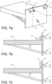
- Fig. 7a-c
- show schematically, in a perspective view and in cross-sectional views, the child seat platform structure with the attachment arrangement according to the alternative embodiment of the disclosure, and
- Fig. 8a-b
- show schematically, in a perspective view and in a cross-sectional view, the vehicle door structure according to the alternative embodiment of the disclosure.
- Various aspects of the disclosure will hereinafter be described in conjunction with the appended drawings to illustrate and not to limit the disclosure, wherein like designations denote like elements, and variations of the described aspects are not restricted to the specifically shown embodiments, but are applicable on other variations of the disclosure.
-
Figures 1 and2a-b schematically show achild seat system 2 for avehicle 1, where thechild seat system 2 comprises achild seat 3. Thechild seat 3 may have a traditional configuration and design with aseat structure 3a, abackrest structure 3b, and aheadrest structure 3c, as schematically illustrated in for examplefigures 3a-b . It should be understood that thebackrest structure 3b and theheadrest structure 3c may be integrated into a common structure or alternatively arranged as separate structures. Theheadrest structure 3c may for example be arranged as an adjustable part of thechild seat 3 connected to thebackrest structure 3b. The respective structures may further be provided with padding and anouter cover structure 3d, where theouter cover structure 3d may be made of suitable fabrics or other suitable materials. Theouter cover structure 3d may be removably arranged on thechild seat 3. The respective child seat structures may each have its ownouter cover structure 3d, or theouter cover structure 3d may be arranged to cover two or more of the child seat structures. - The
child seat 3 is configured for holding a child C within aninterior compartment 5 of thevehicle 1. Thechild seat 3 may be equipped with aseat belt arrangement 3e to hold the child C safely in thechild seat 3 during driving. - According to the disclosure, the
child seat 3 comprises anattachment arrangement 6 adapted for attaching thechild seat 3 to avehicle door structure 4, as shown infigures 3a-d ,4a-c and5a-b . By arranging thechild seat 3 on thevehicle door structure 4, thechild seat 3 is arranged to move with the vehicle door D during opening and closing operations, as schematically illustrated infigures 2a-b . Thevehicle door structure 4 may relate to the entire structure of a vehicle door D, and thechild seat 3 is attached to a side of the vehicle door D facing theinterior compartment 5 when the vehicle door D is closed. Thevehicle door structure 4 may also relate to a part of the vehicle door D, such as for example an interior trim panel or similar structure to which thechild seat 3 is attached, facing theinterior compartment 5 when the vehicle door D is closed. Infigure 2b , thechild seat 3 is attached to thevehicle door structure 4 with the vehicle door D in a closed position PC, and thechild seat 3 is arranged within theinterior compartment 5 without the child C being positioned in thechild seat 3. When thechild seat 3 is attached to the vehicle door D, the child C can be placed in thechild seat 3 when the vehicle door D is in an open position PO, as schematically illustrated infigure 2a . Once the child C has been correctly placed in thechild seat 3, as shown infigure 3b , the vehicle door D can be closed for a safe transportation with the child C positioned in thechild seat 3 and arranged within theinterior compartment 5 of the vehicle. - As shown in the figures, the
child seat 3 further comprises a childseat platform structure 22 attached to and arranged underneath thechild seat 3. Theattachment arrangement 6 is arranged on the childseat platform structure 22. The childseat platform structure 22 may be arranged with a side plate to which parts of theattachment arrangement 6 is connected. Thechild seat 3 may be attached to the childseat platform structure 22 with any suitable attachment means, such as for example screws or rivets. In the illustrated embodiments shown infigures 3a-b and6a , ascrew 25 is arranged for attaching thechild seat 3 to theplatform structure 22. Thechild seat 3 may also be removably attached to the childseat platform structure 22 if desired. The childseat platform structure 22 may be made in a strong lightweight construction of any suitable material, such as for example aluminium, plastic materials, composite materials, or a combination of different materials. - With the described
child seat 3 and the attachment of thechild seat 3 to thevehicle door structure 4, the tasks for a user with putting the child C in thechild seat 3 and securing theseat belt arrangement 3e of thechild seat 3 around the child C is highly simplified compared to a traditional child seat positioned on the seats of the vehicle. The user can easily operate thechild seat 3 when the vehicle door D is in an open position without being limited by the vehicle door D or a narrow vehicle door opening. The attachment of thechild seat 3 to thevehicle door structure 4 is providing better ergonomic working positions for the user. The risk with the child C being non-properly seated is highly reduced compared to traditional child seat solutions due to the simplified operations of the child seat and seat belts for the user. Further, through theattachment arrangement 6, thechild seat 3 may be easily attached to and removed from the vehicle. - The
attachment arrangement 6 of thechild seat 3 comprises one ormore attachment members 7, as for example schematically illustrated infigures 3a-d and4a-c . The one ormore attachment members 7 are adapted for engaging thevehicle door structure 4 for holding thechild seat 3 in position in relation to thevehicle door structure 4. The one ormore attachment members 7 are arranged as one or more attachment hooks 7a attached to the side plate of the childseat platform structure 22. Thevehicle door structure 4 comprises one ormore receiving openings 8 adapted for receiving the one or more attachment hooks 7a of theattachment arrangement 6 for holding thechild seat 3 in position in relation to thevehicle door structure 4, as shown infigures 3a-c and5a-b . The one or more attachment hooks 7a are arranged to engage the one ormore receiving openings 8 of thevehicle door structure 4, as schematically illustrated infigures 3a-d . In the embodiment shown infigures 3a-d ,4a-c , and5a-b , theattachment arrangement 6 comprises twoattachment hooks 7a, and the attachment hooks 7a are arranged to cooperate with two corresponding receivingopenings 8 in thevehicle door structure 4. - As illustrated in for example
figure 3c , the attachment hooks 7a are bent in a shape wherehook tips 7b of the attachment hooks 7a are pointing in a direction downwards when cooperating with the corresponding receivingopenings 8 of thevehicle door structure 4. To attach thechild seat 3 to thevehicle door structure 4, the attachment hooks 7a are aligned with the corresponding receivingopenings 8 and pushed into therespective receiving openings 8. Once the attachment hooks 7a have entered the corresponding receivingopenings 8, thechild seat 3 and the childseat platform structure 22 with the attachment hooks 7a are pushed in a direction downwards to secure thechild seat 3 to thevehicle door structure 4. In this way, the childseat platform structure 22 is being hooked onto thedoor structure 4. Infigures 3a-b , the attachment of thechild seat 3 to thevehicle door structure 4 is schematically illustrated. - In the embodiment illustrated in
figures 3a-d ,4a-c , and5a-b , theattachment arrangement 6 of thechild seat 3 further comprises afirst locking member 11. Thevehicle door structure 4 comprises asecond locking member 12, and the first lockingmember 11 and thesecond locking member 12 are adapted for cooperating with each other for holding thechild seat 3 in locking engagement to thevehicle door structure 4. Thefirst locking member 11 and thesecond locking member 12 are preventing that thechild seat 3 is removed from thevehicle door structure 4 during usage. Thefirst locking member 11 comprises alocking mechanism 13. Thelocking mechanism 13 is adapted for releasably connecting the first lockingmember 11 to thesecond locking member 12. Through the engagement between the first lockingmember 11 and thesecond locking member 12, thechild seat 3 is attachable to and removable from thevehicle door structure 4, and when desired locked in position in relation to thevehicle door structure 4 with thelocking mechanism 13. - As shown in
figures 3a-d and4a-c , thelocking mechanism 13 comprises ahousing structure 14 and anelongated rod structure 15. Therod structure 15 is slidably arranged within thehousing structure 14. Thehousing structure 14 may be arranged as a channel-like or tube-like construction in which therod structure 15 is movably arranged between different positions. Thehousing structure 14 and/or therod structure 15 may be provided with suitable holding means for positioning thehousing structure 14 and therod structure 15 in relation to each other. Therod structure 15 comprises one ormore locking arms 17 pivotably attached to afirst end 15a of therod structure 15. Aninner end 17a of each lockingarm 17 is pivotally attached to therod structure 15 through apivoting mechanism 24, as shown infigures 3c-d . Thepivoting mechanism 24 may for example be arranged as a hinge mechanism or other suitable pivoting attachment means. In the embodiment illustrated infigures 3a-d and 4a-c, therod structure 15 comprises two lockingarms 17, but any suitable number of locking arms may be used. - The one or
more locking arms 17 are pivotable between a first position P1, as illustrated infigures 3a ,3d , and4b , and a second position P2, as illustrated infigures 3b ,3c , and4c . In the first position P1 the one ormore locking arms 17 are aligned with, or essentially aligned with, an axial direction DA of therod structure 15. In the first position P1, therod structure 15 and thehousing structure 14 are insertable into and removable from thesecond locking member 12, and in the second position P2 the one ormore locking arms 17 are arranged at a locking angle α in relation to the axial direction DA for holding thechild seat 3 in locking engagement with thevehicle door structure 4, as illustrated infigure 3c . - As illustrated in
figures 3c and5a-b , thesecond locking member 12 of thevehicle door structure 4 is arranged as an openingstructure 16 in thevehicle door structure 4. The openingstructure 16 is adapted for receiving thehousing structure 14 of thelocking mechanism 13 of the first lockingmember 11. The openingstructure 16 may be provided with reinforcing structures or similar arrangements for a robust connection between thechild seat 3 and thevehicle door structure 4. The openingstructure 16 comprises aninner opening section 16a facing theinterior compartment 5 of thevehicle 1, and anouter opening section 16b, as shown infigures 3c and5b . Theouter opening section 16b is facing the exterior side of thevehicle door structure 4 and may be arranged inside thevehicle door structure 4, for example between an interior trim panel and an outer door structure. - The
vehicle door structure 4 further comprises one or morelocking engagement surfaces 18 arranged in connection to theouter opening section 16a, as for example shown infigures 3a-c and5b . The one or morelocking engagement surfaces 18 are adapted for engaging each of the one ormore locking arms 17 of thelocking mechanism 13 for a secure attachment between thechild seat 3 and thevehicle door structure 4. In the embodiment illustrated infigures 3a-d and5a-b , the openingstructure 16 comprises two oppositely arranged lockingengagement surfaces 18 arranged to cooperate with the corresponding two lockingarms 17. As further illustrated, the locking engagement surfaces may be inclined to correspond to the locking angle α of the lockingarms 17, as for example shown in figure 2c. Thus, in the second position P2 the one ormore locking arms 17 of therod structure 15 are arranged at the locking angle α in relation to the axial direction DA for holding thechild seat 3 in locking engagement with the lockingengagement surfaces 18 of the openingstructure 16, as illustrated infigure 3c . - As shown in
figures 3a-b and4b-c , alever arm 19 is pivotably connected to both thehousing structure 14 and to asecond end 15b of therod structure 15 with suitable connection means, such as for example hinges or pivoting shafts. Thelever arm 19 is adapted for slidingly moving therod structure 15 in relation to thehousing structure 14 between a first rod position PR1, as illustrated infigures 3a and4b , and a second rod position PR2, as illustrated infigure 3b and4c . When operating thelever arm 19, therod structure 15 is displaced in the axial direction DA between the first rod position PR, and the second rod position PR2. As shown infigures 3a-b , therod structure 15 is moving in the axial direction DA in a direction towards thedoor structure 4 when thelever arm 19 is displacing therod structure 15 from the first rod position PR1 to the second rod position PR2. With reference tofigures 3a-b , therod structure 15 is moving to the right in the figure when therod structure 15 is displaced from the first rod position PR1 to the second rod position PR2. Therod structure 15 is moving in the opposite direction away from thedoor structure 4 when thelever arm 19 is displacing therod structure 15 from the second rod position PR2 to the first rod position PR1. With reference tofigures 3a-b , therod structure 15 is moving to the left in the figure when therod structure 15 is displaced from the second rod position PR2 to the first rod position PR1. - As further schematically illustrated in
figures 3a-d , the one ormore locking arms 17 are adapted for being pivotable between the first position P1 and the second position P2 through the sliding movement of therod structure 15 in relation to thehousing structure 14. The construction of therod structure 15 and the lockingarms 17 are configured to move the lockingarms 17 between the respective first and second positions when therod structure 15 is displaced between the first and second rod positions with thelever arm 19. In the first rod position PR1 the one ormore locking arms 17 are arranged in the first position P1, and in the second rod position PR2 the one ormore locking arms 17 are arranged in the second position P2. The movement of the lockingarms 17 in relation to therod structure 15 around thepivoting mechanism 24 may be established with any suitable displacement means. - The
pivoting mechanism 24 may for example comprise gears or similar structures connected to therod structure 15 and the lockingarms 17, for moving the lockingarms 17. The movement of the lockingarms 17 may alternatively be established with one or more electric actuators if desired instead of using thelever arm 19. The one or more electric actuators are configured to displace the lockingarms 17, and may be connected to a power source arranged in thechild seat 3 or in thevehicle 1. The electric actuator may for example be a suitable electric motor connected to a switch mechanism. - The one or
more locking arms 17 may be interconnected by one ormore springs 20, as shown infigures 3c-d , where the one ormore springs 20 are arranged for holding the one or more locking arms in the second position P2. The one ormore locking arms 17 may further be interconnected by one ormore wires 21, where the one ormore wires 21 are arranged for interacting with anactuating mechanism 23 for positioning the one ormore locking arms 17 in the first position P1 when therod structure 15 is positioned in the first rod position PR1, and for positioning the one ormore locking arms 17 in the second position P2 when therod structure 15 is positioned in the second rod position PR2. In the embodiment illustrated infigures 3c-d , asingle torsion spring 20 is connected to and arranged between the two lockingarms 17, and asingle wire 21 is connected to and arranged between the two lockingarms 17. Thetorsion spring 20 is configured in an initial or unloaded state when the lockingarms 17 are positioned in the second position P2, and configured in a loaded state in the first position P1. In the first position P1, the lockingarms 17 are thus striving towards the stable second position P2 through action from thespring 20. Depending on the attachment of thewire 21 to the lockingarms 17, thewire 21 may be made of a suitable elastic or non-elastic material. It should be understood that any suitable type of spring could be used. - The
actuating mechanism 23 may be arranged as a movable rod structure connected to a mid-section of thewire 21. When displacing therod structure 15 in the axial direction DA in a direction towards the interior compartment 5a, from the second rod position PR2 where the lockingarms 17 are arranged in the second position P2 as illustrated infigure 3c , theactuating mechanism 23 and thewire 21 are displacing the lockingarms 17 towards the first position P1. By further displacing thewire 21 in the same direction, the lockingarms 17 are moved to the first position P1, as shown infigure 3d . When displacing the lockingarms 17 from the second position P2 to the first position P1, the force from theactuating mechanism 23 via thewire 21 is loading thespring 20. To move the lockingarms 17 from the first position P1 to the second position P2, therod structure 15 is moved in the opposite direction and theactuating mechanism 23 is released, wherein the force from thespring 20 is displacing the lockingarms 17. Theactuating mechanism 23 may be configured as a non-moving rod structure attached to thehousing structure 14 for impacting the lockingarms 17 via thewire 21 upon movement of therod structure 15. - In an alternative embodiment, the
actuating mechanism 23 may be configured as a moving mechanism, and any suitable actuating means may be used for displacing theactuating mechanism 23 in relation to therod structure 15, such as for example a gear and pinion construction, a wire construction, or an electrical actuator. Theactuating mechanism 23 may be arranged to move in the axial direction DA in relation to therod structure 15 upon activation of the rod structure between the first rod position PR1 and the second rod position PR2. Theactuating mechanism 23 may be slidably arranged in relation to therod structure 15, and positioned in a parallel, or essentially parallel, external or internal relationship. If arranging theactuating mechanism 23 inside therod structure 15, therod structure 15 may be arranged as a tubular construction with a channel for theactuating mechanism 23. Theactuating mechanism 23 may suitably be actuated with thelever arm 19 when displacing therod structure 15 between the first rod position PR1 and the second rod position PR2. - To operate the
child seat system 2 of the embodiment schematically illustrated infigures 3a-d ,4a-c , and5a-b , and to attach thechild seat 3 to thevehicle door structure 4, thelever arm 19 with therod structure 15 are arranged in the first rod position PR1 in order to prepare thechild seat 3 for being attached to thevehicle door structure 4. In the first rod position PR1, the lockingarms 17 are as described above arranged in the first position P1 shown infigure 3a . In the first rod position PR1, the lockingarms 17 are at least partly arranged inside thehousing structure 14 for a convenient attachment of thechild seat 4 to thevehicle door structure 4. To attach thechild seat 3 to thevehicle door structure 4, the attachment hooks 7a are aligned with the corresponding receivingopenings 8 of thevehicle door structure 4, and the attachment hooks 7a are pushed into therespective receiving openings 8. Once the attachment hooks 7a have entered the corresponding receivingopenings 8, thechild seat 3 with the attachment hooks 7a are pushed in a direction downwards to secure thechild seat 3 to thevehicle door structure 4. At the same time, thehousing structure 14 is aligned with the openingstructure 16 and pushed into the openingstructure 16 into the position shown infigure 3a , together with therod structure 15 and the lockingarms 17. When the attachment hooks 7a are connected to thecorresponding receiving openings 8 and thehousing structure 14 is in a correct position in relation to theopening structure 16, thechild seat 3 is prepared for being locked to thevehicle door structure 4. In the described position, thelever arm 19 is moved from the position illustrated infigure 3a to the position illustrated infigure 3b . With the movement of thelever arm 19, therod structure 15 with the lockingarms 17 are displaced in relation to thehousing structure 14 from the first rod position PR1 to the second rod position PR2 into thevehicle door structure 4, and at the same time the lockingarms 17 are moved from the first position P1 to the second position P2. During the movement of therod structure 15 from the first rod position PR1 to the second rod position PR2, the lockingarms 17 are moved from the first position P1 to the second position P2 through the engagement with theactuating mechanism 23. In the second rod position PR2, the lockingarms 17 are arranged in the second position P2, and the lockingarms 17 are locking thechild seat 3 to thevehicle door structure 4, preventing thechild seat 3 from being removed from thevehicle door structure 4. The lockingarms 17 are engaging the lockingengagement surfaces 18 for a secure attachment of thechild seat 3 to thevehicle door structure 4. The lockingarms 17 and/or the lockingengagement surfaces 18 may be arranged with suitable materials for increased holding capacity and long-lasting capabilities, such as for example polymers, or rubber materials with high friction. Thelever arm 19 may further be arranged with a suitable locking arrangement for preventing unwanted or accidental movement of thelever arm 19 and therod structure 15 from the second rod position PR2 to the first rod position PR1. - To remove the
child seat 3 from the vehicle door structure, thelocking mechanism 13 is operated in the reverse order. Thelever arm 19 and therod structure 15 with the lockingarms 17 are moved from the second rod position PR2 illustrated infigure 3b to the first rod position PR1 illustrated infigure 3a . Upon displacement of therod structure 15, the lockingarms 17 are displaced from the second position P2 to the first position P1, and thechild seat 3 can be removed from thevehicle door structure 4. - An alternative embodiment of the
child seat system 2 is shown infigures 6a-b ,7a-c , and8a-b . Thechild seat 3 is having a configuration similar to the one described above, and thechild seat 3 comprises anattachment arrangement 6 adapted for attaching thechild seat 3 to avehicle door structure 4. In this embodiment, theattachment arrangement 6 comprises threeattachment hooks 7a attached to the side plate of the childseat platform structure 22, and the attachment hooks 7a are arranged to cooperate with three corresponding receivingopenings 8 in thevehicle door structure 4. As illustrated infigures 6b , and7b-c , the attachment hooks 7a are bent in a shape wherehook tips 7b of the attachment hooks 7a are pointing in a direction downwards when cooperating with the corresponding receivingopenings 8. To attach thechild seat 3 to thevehicle door structure 4, the attachment hooks 7a are aligned with the corresponding receivingopenings 8 and pushed into therespective receiving openings 8. Once the attachment hooks 7a have entered the corresponding receivingopenings 8, the child seat with the attachment hooks are pushed in a direction downwards to secure thechild seat 3 to thevehicle door structure 4. Infigure 6a , the attachment of thechild seat 3 to thevehicle door structure 4 is schematically illustrated. - In the alternative embodiment shown in
figures 6a-b ,7a-c , and8a-b , theattachment arrangement 6 further comprises a lockinglever 9 movably connected to the childseat platform structure 22. The lockinglever 9 is pivotably arranged between an unlocked position PU, as schematically illustrated infigure 7b , and a locked position PL, as schematically illustrated infigures 6a-b and7c . When the lockinglever 9 is arranged in the unlocked position Pu thechild seat 3 is attachable to and removable from thevehicle door structure 4. The lockinglever 9 comprises a lockingsurface 10, and the lockingsurface 10 is adapted for engaging a suitablevehicle door surface 4a of thevehicle door structure 4 when the lockinglever 9 is arranged in the locked position PL preventing thechild seat 3 from being removed from thevehicle door structure 4, as schematically illustrated infigure 6a . - To operate the
child seat system 2 of the alternative embodiment schematically illustrated infigures 6a-b ,7a-c , and8a-b , and to attach thechild seat 3 to thevehicle door structure 4, the lockinglever 9 is arranged in the unlocked position Pu in order to prepare thechild seat 3 for being attached to thevehicle door structure 4. To attach thechild seat 3 to thevehicle door structure 4, the attachment hooks 7a are aligned with the corresponding receivingopenings 8 of thevehicle door structure 4, and the attachment hooks 7a are pushed into therespective receiving openings 8. Once the attachment hooks 7a have entered the corresponding receivingopenings 8, the child seat with the attachment hooks 7a are pushed in a direction downwards to secure thechild seat 3 to thevehicle door structure 4. Infigure 6a , the attachment of thechild seat 3 to thevehicle door structure 4 is schematically illustrated. When the attachment hooks 7a are holding thechild seat 3 in connection to thevehicle door structure 4, the lockinglever 9 is moved into the locked position PL through a pivoting movement around alever pivot point 9a, as illustrated infigure 6a . The lockinglever 9 may comprise any suitable arrangement for pivoting the lockinglever 9 in relation to the childseat platform structure 22, such as an axle arrangement or similar structure. In the locked position PL, the lockingsurface 10 of the lockinglever 9 is engaging thevehicle door surface 4a of thevehicle door structure 4, and through the engagement between the lockingsurface 10 and thevehicle door surface 4a, thechild seat 3 is prevented from being removed from thevehicle door structure 4. Thevehicle door surface 4a may be any suitable surface for engaging the lockingsurface 10. Thevehicle door surface 4a and/or the lockingsurface 10 may be arranged with suitable materials for increased holding capacity and long-lasting capabilities, such as for example polymers, or a rubber materials with high friction. The lockinglever 9 may be made of any suitable material, such as for example metals, plastic materials, composite materials or a combination of different materials. The lockinglever 9 may further be arranged with a suitable locking arrangement for preventing unwanted or accidental movement of the lockinglever 9 from the locked position PL to the unlocked position Pu. - To remove the
child seat 3 from the vehicle door structure, the lockinglever 9 is operated in the reverse order. The lockinglever 9 is moved from the locked position PL to the unlocked position Pu, and thechild seat 3 can be removed from thevehicle door structure 4. - It will be appreciated that the above description is merely exemplary in nature and is not intended to limit the present disclosure, its application or uses. While specific examples have been described in the specification and illustrated in the drawings, it will be understood by those of ordinary skill in the art that various changes may be made and equivalents may be substituted for elements thereof as long as they remain within the scope of the present disclosure as defined in the claims. Furthermore, modifications may be made to adapt a particular situation or material to the teachings of the present disclosure as long as they remain within the scope thereof.
- Therefore, it is intended that the present disclosure not be limited to the particular examples illustrated by the drawings and described in the specification as the best mode presently contemplated for carrying out the teachings of the present disclosure, but that the scope of the present disclosure will include any embodiments falling within the scope of the appended claims. Reference signs mentioned in the claims should not be seen as limiting the extent of the matter protected by the claims, and their sole function is to make claims easier to understand.
-
- 1:
- Vehicle
- 2:
- Child seat system
- 3:
- Child seat
- 3a:
- Seat structure
- 3b.
- Backrest structure
- 3c:
- Headrest structure
- 3d:
- Outer cover structure
- 3e:
- Seat belt arrangement
- 4:
- Vehicle door structure
- 4a:
- Vehicle door surface
- 5:
- Interior compartment
- 6:
- Attachment arrangement
- 7:
- Attachment members
- 7a:
- Attachment hooks
- 7b:
- Hook tips
- 8:
- Receiving openings
- 9:
- Locking lever
- 9a:
- Lever pivot point
- 10:
- Locking surface
- 11:
- First locking member
- 12:
- Second locking member
- 13:
- Locking mechanism
- 14:
- Housing structure
- 15:
- Rod structure
- 15a:
- First end, Rod structure
- 15b:
- Second end, Rod structure
- 16:
- Opening structure
- 16a:
- Inner opening section
- 16b:
- Outer opening section
- 17:
- Locking arm
- 17a:
- Inner end, Locking arm
- 18:
- Locking engagement surface
- 19:
- Lever arm
- 20:
- Spring
- 21:
- Wire
- 22:
- Child seat platform structure
- 23:
- Actuating mechanism
- 24:
- Pivoting mechanism
- 25:
- Screw
- C:
- Child
- D:
- Vehicle door
- PC:
- Closed position
- PO:
- Open position
- DA:
- Axial direction
- P1:
- First position
- P2:
- Second position
- PR1:
- First rod position
- PR2:
- Second rod position
Claims (14)
- A child seat (3) for a vehicle (1), wherein the child seat (3) is configured for holding a child within an interior compartment (5) of the vehicle (1), wherein the child seat (3) comprises an attachment arrangement (6) adapted for attaching the child seat (3) to a vehicle door structure (4),
characterized in that the child seat (3) further comprises a child seat platform structure (22) attached to and arranged underneath the child seat (3), wherein the attachment arrangement (6) is arranged on the child seat platform structure (22). - The child seat (3) according to claim 1,
characterized in that the attachment arrangement (6) comprises one or more attachment members (7), wherein the one or more attachment members (7) are adapted for engaging the vehicle door structure (4) for holding the child seat (3) in position in relation to the vehicle door structure (4). - The child seat (3) according to claim 2,
characterized in that the one or more attachment members (7) are arranged as one or more attachment hooks (7a), wherein the one or more attachment hooks (7a) are adapted for engaging one or more receiving openings (8) of the vehicle door structure (4) for holding the child seat (3) in position in relation to the vehicle door structure (4). - The child seat (3) according to any of the preceding claims,
characterized in that the attachment arrangement (6) further comprises a locking lever (9), wherein the locking lever (9) is pivotably arranged between an unlocked position (Pu) and a locked position (PL), wherein when the locking lever (9) is arranged in the unlocked position (Pu) the child seat (3) is attachable to and removable from the vehicle door structure (4), wherein the locking lever (9) comprises a locking surface (10), wherein the locking surface (10) is adapted for engaging a vehicle door surface (4a) of the vehicle door structure (4) when the locking lever (9) is arranged in the locked position (PL) preventing the child seat (3) from being removed from the vehicle door structure (4). - The child seat (3) according to any of claims 1 to 3,
characterized in that the attachment arrangement (6) further comprises a first locking member (11), wherein the first locking member (11) is adapted for cooperating with a second locking member (12) of the vehicle door structure (4) for holding the child seat (3) in locking engagement to the vehicle door structure (4) preventing the child seat (3) from being removed from the vehicle door structure (4). - The child seat (3) according to claim 5,
characterized in that the first locking member (11) comprises a locking mechanism (13) adapted for releasably connecting the first locking member (11) to the second locking member (12), wherein the child seat (3) is adapted for being attachable to and removable from the vehicle door structure (4). - The child seat (3) according to claim 6,
characterized in that the locking mechanism (13) comprises a housing structure (14) and an elongated rod structure (15), wherein the rod structure (15) is slidably arranged within the housing structure (14). - The child seat (3) according to claim 7,
characterized in that the rod structure (15) comprises one or more locking arms (17) pivotably attached to a first end (15a) of the rod structure (15), wherein the one or more locking arms (17) are pivotable between a first position (P1) and a second position (P2), wherein in the first position (P1) the one or more locking arms (17) are aligned with, or essentially aligned with, an axial direction (DA) of the rod structure (15), wherein in the first position (P1) the rod structure (15) and the housing structure (14) are adapted to be insertable into and removable from the second locking member (12), and wherein in the second position (P2) the one or more locking arms (17) are arranged at a locking angle (α) in relation to the axial direction (DA) for holding the child seat (3) in locking engagement with an opening structure (16). - The child seat (3) according to claim 8,
characterized in that a lever arm (19) is connected to the housing structure (14) and to a second end (15b) of the rod structure (15), wherein the lever arm (19) is adapted for slidingly moving the rod structure (15) in relation to the housing structure (14) between a first rod position (PR1) and a second rod position (PR2), wherein the one or more locking arms (17) are adapted for being pivotable between the first position (P1) and the second position (P2) through the sliding movement of the rod structure (15) in relation to the housing structure (14), wherein in the first rod position (PR1) the one or more locking arms (17) are arranged in the first position (P1), and wherein in the second rod position (PR2) the one or more locking arms (17) are arranged in the second position (P2). - The child seat (3) according to claim 9,
characterized in that the one or more locking arms (17) are interconnected by one or more springs (20), wherein the one or more springs (20) are adapted for holding the one or more locking arms in the second position (P2). - The child seat (3) according to claim 9 or 10,
characterized in that the one or more locking arms (17) are interconnected by one or more wires (21), wherein the one or more wires (21) are adapted for interacting with the rod structure (15) for positioning the one or more locking arms (17) in the first position (P1) when the rod structure (15) is positioned in the first rod position (PR1). - A child seat system (2) for a vehicle (1) comprising a child seat (3) according to any of claims 1-11, wherein the child seat (3) is configured for holding a child within an interior compartment (5) of the vehicle (1),
characterized in that the child seat system (2) further comprises a vehicle door structure (4), wherein the child seat (3) is adapted for being attachable to the vehicle door structure (4). - The child seat system (2) according to claim 12,
characterized in that the child seat (3) comprises an attachment arrangement (6) for attaching the child seat (3) to the vehicle door structure (4), wherein the attachment arrangement (6) comprises one or more attachment hooks (7a), and wherein the vehicle door structure (4) comprises one or more receiving openings (8) adapted for receiving the one or more attachment hooks (7a) for holding the child seat (3) in position in relation to the vehicle door structure (4). - The child seat system (2) according to claim 13,
characterized in that the attachment arrangement (6) comprises a first locking member (11) and the vehicle door structure (4) comprises a second locking member (12), wherein the first locking member (11) is adapted for cooperating with the second locking member (12) for holding the child seat (3) in locking engagement to the vehicle door structure (4) preventing the child seat (3) from being removed from the vehicle door structure (4).
Priority Applications (4)
| Application Number | Priority Date | Filing Date | Title |
|---|---|---|---|
| EP20155143.9A EP3858661B1 (en) | 2020-02-03 | 2020-02-03 | A child seat and a child seat system |
| PCT/CN2020/142409 WO2021155730A1 (en) | 2020-02-03 | 2020-12-31 | A child seat, a vehicle door structure, a child seat system, and a method for operating a child seat system |
| CN202080094923.1A CN115003551B (en) | 2020-02-03 | 2020-12-31 | Child seat, door structure, child seat system and method for operating child seat system |
| US17/873,026 US20220371481A1 (en) | 2020-02-03 | 2022-07-25 | Child seat, a vehicle door structure, a child seat system, and a method for operating a child seat system |
Applications Claiming Priority (1)
| Application Number | Priority Date | Filing Date | Title |
|---|---|---|---|
| EP20155143.9A EP3858661B1 (en) | 2020-02-03 | 2020-02-03 | A child seat and a child seat system |
Publications (2)
| Publication Number | Publication Date |
|---|---|
| EP3858661A1 EP3858661A1 (en) | 2021-08-04 |
| EP3858661B1 true EP3858661B1 (en) | 2023-04-19 |
Family
ID=69467418
Family Applications (1)
| Application Number | Title | Priority Date | Filing Date |
|---|---|---|---|
| EP20155143.9A Active EP3858661B1 (en) | 2020-02-03 | 2020-02-03 | A child seat and a child seat system |
Country Status (4)
| Country | Link |
|---|---|
| US (1) | US20220371481A1 (en) |
| EP (1) | EP3858661B1 (en) |
| CN (1) | CN115003551B (en) |
| WO (1) | WO2021155730A1 (en) |
Family Cites Families (13)
| Publication number | Priority date | Publication date | Assignee | Title |
|---|---|---|---|---|
| US4226462A (en) * | 1978-08-31 | 1980-10-07 | Gabriel Wellett | Car door transfer seat for handicapped persons |
| DE9311789U1 (en) * | 1993-08-07 | 1993-10-07 | Volkswagen Ag, 38440 Wolfsburg | child seat |
| DE19843148B4 (en) * | 1997-06-03 | 2004-08-26 | Richard Ambros | Safety seat arranged at right angles to the direction of travel, which is attached to a passenger door and is ultimately pushed back when the door is closed |
| JP2002144925A (en) * | 2000-11-15 | 2002-05-22 | Nissan Motor Co Ltd | Door-integrated seat support structure |
| US6547303B1 (en) * | 2001-08-13 | 2003-04-15 | Johnson Controls Technology Company | Pivoting seating system |
| CN1342565A (en) * | 2001-09-25 | 2002-04-03 | 邵华 | Door combined with seat for automobile |
| DE102004013799A1 (en) * | 2004-03-20 | 2005-10-13 | Adam Opel Ag | System for swiveling vehicle seat comprises frame on which seat is mounted which is connected by pivot to support frame fixed to floor, lever which locks seat against floor frame being operated closing vehicle door |
| DE102004013800A1 (en) * | 2004-03-20 | 2005-10-06 | Adam Opel Ag | Safety seat for child, comprising adapter unit with vertical rotation axle for moving seat |
| US7106207B1 (en) * | 2005-06-15 | 2006-09-12 | Marchan Leonito E | Vehicle child seat alarm |
| US7469948B2 (en) * | 2007-05-09 | 2008-12-30 | Gm Global Technology Operations, Inc. | Apparatus for extending vehicle cargo space and method for same |
| JP5497608B2 (en) * | 2010-10-07 | 2014-05-21 | 網矢 貞幸 | Automotive door |
| CN205440043U (en) * | 2015-08-03 | 2016-08-10 | 苏州逗乐儭童用品有限公司 | Children's seat for vehicle with alarm appts |
| US10596923B2 (en) * | 2017-03-06 | 2020-03-24 | Ford Global Technologies, Llc | Door mounted vehicle seat |
-
2020
- 2020-02-03 EP EP20155143.9A patent/EP3858661B1/en active Active
- 2020-12-31 WO PCT/CN2020/142409 patent/WO2021155730A1/en active Application Filing
- 2020-12-31 CN CN202080094923.1A patent/CN115003551B/en active Active
-
2022
- 2022-07-25 US US17/873,026 patent/US20220371481A1/en active Pending
Also Published As
| Publication number | Publication date |
|---|---|
| WO2021155730A1 (en) | 2021-08-12 |
| CN115003551A (en) | 2022-09-02 |
| CN115003551B (en) | 2024-06-11 |
| US20220371481A1 (en) | 2022-11-24 |
| EP3858661A1 (en) | 2021-08-04 |
Similar Documents
| Publication | Publication Date | Title |
|---|---|---|
| EP3617433B1 (en) | Retractable outside door handle assembly for vehicle | |
| US7887134B2 (en) | Interlock for a seat recliner mechanism | |
| US10358069B2 (en) | Armrest assembly for vehicle interior | |
| US20050285410A1 (en) | Convertible top latch | |
| EP2415629A1 (en) | Seat slide apparatus for vehicle | |
| EP2209667A1 (en) | Seat recliner mechanism with fold-flat feature | |
| US7739836B2 (en) | Vehicle door with selective full open positions | |
| CN107820529B (en) | With the pivoting device for motor vehicles being easily installed with safer pivot bearings | |
| US20180105078A1 (en) | Multi-functional vehicle seat | |
| US10293939B2 (en) | Anti-rattling device for pallets in cargo aircraft | |
| CN112977222A (en) | Variable handle device for getting on and off vehicle | |
| EP3858661B1 (en) | A child seat and a child seat system | |
| KR200391927Y1 (en) | Lock-assembly for armrest box of automobile | |
| CN108367694B (en) | Multi-position locking device for the back of a motor vehicle rear seat | |
| CN107250473B (en) | Motor vehicle door lock | |
| CN103670083A (en) | Closure device for compartment which can be closed by flap in motor vehicle | |
| CN115303148A (en) | Vehicle seat collision protection device and vehicle seat | |
| US11427063B2 (en) | Locking device having detent hooks and top having a locking device | |
| US11752910B2 (en) | Armrest arrangement for a motor vehicle | |
| US6045189A (en) | Seat back lock with pivoting locking member | |
| CN108349437B (en) | Unlockable luggage compartment bottom device for a luggage compartment of a motor vehicle | |
| US20230294491A1 (en) | Side impact restraint protection system for a vehicle | |
| DE102017211667B4 (en) | Cover system for a through-loading area of a vehicle interior | |
| JP7363005B2 (en) | car lock | |
| CN114008273B (en) | Movable control module for hydraulic machine with locking feature |
Legal Events
| Date | Code | Title | Description |
|---|---|---|---|
| PUAI | Public reference made under article 153(3) epc to a published international application that has entered the european phase |
Free format text: ORIGINAL CODE: 0009012 |
|
| STAA | Information on the status of an ep patent application or granted ep patent |
Free format text: STATUS: REQUEST FOR EXAMINATION WAS MADE |
|
| 17P | Request for examination filed |
Effective date: 20200203 |
|
| AK | Designated contracting states |
Kind code of ref document: A1 Designated state(s): AL AT BE BG CH CY CZ DE DK EE ES FI FR GB GR HR HU IE IS IT LI LT LU LV MC MK MT NL NO PL PT RO RS SE SI SK SM TR |
|
| GRAP | Despatch of communication of intention to grant a patent |
Free format text: ORIGINAL CODE: EPIDOSNIGR1 |
|
| STAA | Information on the status of an ep patent application or granted ep patent |
Free format text: STATUS: GRANT OF PATENT IS INTENDED |
|
| INTG | Intention to grant announced |
Effective date: 20221107 |
|
| RAP3 | Party data changed (applicant data changed or rights of an application transferred) |
Owner name: ZHEJIANG GEELY HOLDING GROUP CO., LTD. Owner name: NINGBO GEELY AUTOMOBILE RESEARCH & DEVELOPMENT CO., LTD. |
|
| GRAS | Grant fee paid |
Free format text: ORIGINAL CODE: EPIDOSNIGR3 |
|
| GRAA | (expected) grant |
Free format text: ORIGINAL CODE: 0009210 |
|
| STAA | Information on the status of an ep patent application or granted ep patent |
Free format text: STATUS: THE PATENT HAS BEEN GRANTED |
|
| AK | Designated contracting states |
Kind code of ref document: B1 Designated state(s): AL AT BE BG CH CY CZ DE DK EE ES FI FR GB GR HR HU IE IS IT LI LT LU LV MC MK MT NL NO PL PT RO RS SE SI SK SM TR |
|
| REG | Reference to a national code |
Ref country code: GB Ref legal event code: FG4D |
|
| REG | Reference to a national code |
Ref country code: CH Ref legal event code: EP |
|
| REG | Reference to a national code |
Ref country code: DE Ref legal event code: R096 Ref document number: 602020009774 Country of ref document: DE |
|
| REG | Reference to a national code |
Ref country code: IE Ref legal event code: FG4D |
|
| REG | Reference to a national code |
Ref country code: AT Ref legal event code: REF Ref document number: 1560958 Country of ref document: AT Kind code of ref document: T Effective date: 20230515 |
|
| REG | Reference to a national code |
Ref country code: LT Ref legal event code: MG9D |
|
| REG | Reference to a national code |
Ref country code: NL Ref legal event code: MP Effective date: 20230419 |
|
| REG | Reference to a national code |
Ref country code: AT Ref legal event code: MK05 Ref document number: 1560958 Country of ref document: AT Kind code of ref document: T Effective date: 20230419 |
|
| PG25 | Lapsed in a contracting state [announced via postgrant information from national office to epo] |
Ref country code: NL Free format text: LAPSE BECAUSE OF FAILURE TO SUBMIT A TRANSLATION OF THE DESCRIPTION OR TO PAY THE FEE WITHIN THE PRESCRIBED TIME-LIMIT Effective date: 20230419 |
|
| PG25 | Lapsed in a contracting state [announced via postgrant information from national office to epo] |
Ref country code: SE Free format text: LAPSE BECAUSE OF FAILURE TO SUBMIT A TRANSLATION OF THE DESCRIPTION OR TO PAY THE FEE WITHIN THE PRESCRIBED TIME-LIMIT Effective date: 20230419 Ref country code: PT Free format text: LAPSE BECAUSE OF FAILURE TO SUBMIT A TRANSLATION OF THE DESCRIPTION OR TO PAY THE FEE WITHIN THE PRESCRIBED TIME-LIMIT Effective date: 20230821 Ref country code: NO Free format text: LAPSE BECAUSE OF FAILURE TO SUBMIT A TRANSLATION OF THE DESCRIPTION OR TO PAY THE FEE WITHIN THE PRESCRIBED TIME-LIMIT Effective date: 20230719 Ref country code: ES Free format text: LAPSE BECAUSE OF FAILURE TO SUBMIT A TRANSLATION OF THE DESCRIPTION OR TO PAY THE FEE WITHIN THE PRESCRIBED TIME-LIMIT Effective date: 20230419 Ref country code: AT Free format text: LAPSE BECAUSE OF FAILURE TO SUBMIT A TRANSLATION OF THE DESCRIPTION OR TO PAY THE FEE WITHIN THE PRESCRIBED TIME-LIMIT Effective date: 20230419 |
|
| PG25 | Lapsed in a contracting state [announced via postgrant information from national office to epo] |
Ref country code: RS Free format text: LAPSE BECAUSE OF FAILURE TO SUBMIT A TRANSLATION OF THE DESCRIPTION OR TO PAY THE FEE WITHIN THE PRESCRIBED TIME-LIMIT Effective date: 20230419 Ref country code: PL Free format text: LAPSE BECAUSE OF FAILURE TO SUBMIT A TRANSLATION OF THE DESCRIPTION OR TO PAY THE FEE WITHIN THE PRESCRIBED TIME-LIMIT Effective date: 20230419 Ref country code: LV Free format text: LAPSE BECAUSE OF FAILURE TO SUBMIT A TRANSLATION OF THE DESCRIPTION OR TO PAY THE FEE WITHIN THE PRESCRIBED TIME-LIMIT Effective date: 20230419 Ref country code: LT Free format text: LAPSE BECAUSE OF FAILURE TO SUBMIT A TRANSLATION OF THE DESCRIPTION OR TO PAY THE FEE WITHIN THE PRESCRIBED TIME-LIMIT Effective date: 20230419 Ref country code: IS Free format text: LAPSE BECAUSE OF FAILURE TO SUBMIT A TRANSLATION OF THE DESCRIPTION OR TO PAY THE FEE WITHIN THE PRESCRIBED TIME-LIMIT Effective date: 20230819 Ref country code: HR Free format text: LAPSE BECAUSE OF FAILURE TO SUBMIT A TRANSLATION OF THE DESCRIPTION OR TO PAY THE FEE WITHIN THE PRESCRIBED TIME-LIMIT Effective date: 20230419 Ref country code: GR Free format text: LAPSE BECAUSE OF FAILURE TO SUBMIT A TRANSLATION OF THE DESCRIPTION OR TO PAY THE FEE WITHIN THE PRESCRIBED TIME-LIMIT Effective date: 20230720 Ref country code: AL Free format text: LAPSE BECAUSE OF FAILURE TO SUBMIT A TRANSLATION OF THE DESCRIPTION OR TO PAY THE FEE WITHIN THE PRESCRIBED TIME-LIMIT Effective date: 20230419 |
|
| PG25 | Lapsed in a contracting state [announced via postgrant information from national office to epo] |
Ref country code: FI Free format text: LAPSE BECAUSE OF FAILURE TO SUBMIT A TRANSLATION OF THE DESCRIPTION OR TO PAY THE FEE WITHIN THE PRESCRIBED TIME-LIMIT Effective date: 20230419 |
|
| PG25 | Lapsed in a contracting state [announced via postgrant information from national office to epo] |
Ref country code: SK Free format text: LAPSE BECAUSE OF FAILURE TO SUBMIT A TRANSLATION OF THE DESCRIPTION OR TO PAY THE FEE WITHIN THE PRESCRIBED TIME-LIMIT Effective date: 20230419 |
|
| REG | Reference to a national code |
Ref country code: DE Ref legal event code: R097 Ref document number: 602020009774 Country of ref document: DE |
|
| PG25 | Lapsed in a contracting state [announced via postgrant information from national office to epo] |
Ref country code: SM Free format text: LAPSE BECAUSE OF FAILURE TO SUBMIT A TRANSLATION OF THE DESCRIPTION OR TO PAY THE FEE WITHIN THE PRESCRIBED TIME-LIMIT Effective date: 20230419 Ref country code: SK Free format text: LAPSE BECAUSE OF FAILURE TO SUBMIT A TRANSLATION OF THE DESCRIPTION OR TO PAY THE FEE WITHIN THE PRESCRIBED TIME-LIMIT Effective date: 20230419 Ref country code: RO Free format text: LAPSE BECAUSE OF FAILURE TO SUBMIT A TRANSLATION OF THE DESCRIPTION OR TO PAY THE FEE WITHIN THE PRESCRIBED TIME-LIMIT Effective date: 20230419 Ref country code: EE Free format text: LAPSE BECAUSE OF FAILURE TO SUBMIT A TRANSLATION OF THE DESCRIPTION OR TO PAY THE FEE WITHIN THE PRESCRIBED TIME-LIMIT Effective date: 20230419 Ref country code: DK Free format text: LAPSE BECAUSE OF FAILURE TO SUBMIT A TRANSLATION OF THE DESCRIPTION OR TO PAY THE FEE WITHIN THE PRESCRIBED TIME-LIMIT Effective date: 20230419 Ref country code: CZ Free format text: LAPSE BECAUSE OF FAILURE TO SUBMIT A TRANSLATION OF THE DESCRIPTION OR TO PAY THE FEE WITHIN THE PRESCRIBED TIME-LIMIT Effective date: 20230419 |
|
| PLBE | No opposition filed within time limit |
Free format text: ORIGINAL CODE: 0009261 |
|
| STAA | Information on the status of an ep patent application or granted ep patent |
Free format text: STATUS: NO OPPOSITION FILED WITHIN TIME LIMIT |
|
| 26N | No opposition filed |
Effective date: 20240122 |
|
| PGFP | Annual fee paid to national office [announced via postgrant information from national office to epo] |
Ref country code: DE Payment date: 20240213 Year of fee payment: 5 Ref country code: GB Payment date: 20240221 Year of fee payment: 5 |
|
| PG25 | Lapsed in a contracting state [announced via postgrant information from national office to epo] |
Ref country code: SI Free format text: LAPSE BECAUSE OF FAILURE TO SUBMIT A TRANSLATION OF THE DESCRIPTION OR TO PAY THE FEE WITHIN THE PRESCRIBED TIME-LIMIT Effective date: 20230419 |
|
| PG25 | Lapsed in a contracting state [announced via postgrant information from national office to epo] |
Ref country code: SI Free format text: LAPSE BECAUSE OF FAILURE TO SUBMIT A TRANSLATION OF THE DESCRIPTION OR TO PAY THE FEE WITHIN THE PRESCRIBED TIME-LIMIT Effective date: 20230419 Ref country code: IT Free format text: LAPSE BECAUSE OF FAILURE TO SUBMIT A TRANSLATION OF THE DESCRIPTION OR TO PAY THE FEE WITHIN THE PRESCRIBED TIME-LIMIT Effective date: 20230419 |
|
| PGFP | Annual fee paid to national office [announced via postgrant information from national office to epo] |
Ref country code: FR Payment date: 20240227 Year of fee payment: 5 |