EP3858642B1 - Tire with resonators for noise reduction - Google Patents
Tire with resonators for noise reduction Download PDFInfo
- Publication number
- EP3858642B1 EP3858642B1 EP20206988.6A EP20206988A EP3858642B1 EP 3858642 B1 EP3858642 B1 EP 3858642B1 EP 20206988 A EP20206988 A EP 20206988A EP 3858642 B1 EP3858642 B1 EP 3858642B1
- Authority
- EP
- European Patent Office
- Prior art keywords
- unit
- main groove
- flow path
- neck
- resonance
- Prior art date
- Legal status (The legal status is an assumption and is not a legal conclusion. Google has not performed a legal analysis and makes no representation as to the accuracy of the status listed.)
- Active
Links
Images




Classifications
-
- B—PERFORMING OPERATIONS; TRANSPORTING
- B60—VEHICLES IN GENERAL
- B60C—VEHICLE TYRES; TYRE INFLATION; TYRE CHANGING; CONNECTING VALVES TO INFLATABLE ELASTIC BODIES IN GENERAL; DEVICES OR ARRANGEMENTS RELATED TO TYRES
- B60C11/00—Tyre tread bands; Tread patterns; Anti-skid inserts
- B60C11/03—Tread patterns
- B60C11/0318—Tread patterns irregular patterns with particular pitch sequence
-
- B—PERFORMING OPERATIONS; TRANSPORTING
- B60—VEHICLES IN GENERAL
- B60C—VEHICLE TYRES; TYRE INFLATION; TYRE CHANGING; CONNECTING VALVES TO INFLATABLE ELASTIC BODIES IN GENERAL; DEVICES OR ARRANGEMENTS RELATED TO TYRES
- B60C11/00—Tyre tread bands; Tread patterns; Anti-skid inserts
- B60C11/03—Tread patterns
-
- B—PERFORMING OPERATIONS; TRANSPORTING
- B60—VEHICLES IN GENERAL
- B60C—VEHICLE TYRES; TYRE INFLATION; TYRE CHANGING; CONNECTING VALVES TO INFLATABLE ELASTIC BODIES IN GENERAL; DEVICES OR ARRANGEMENTS RELATED TO TYRES
- B60C19/00—Tyre parts or constructions not otherwise provided for
- B60C19/002—Noise damping elements provided in the tyre structure or attached thereto, e.g. in the tyre interior
-
- B—PERFORMING OPERATIONS; TRANSPORTING
- B60—VEHICLES IN GENERAL
- B60C—VEHICLE TYRES; TYRE INFLATION; TYRE CHANGING; CONNECTING VALVES TO INFLATABLE ELASTIC BODIES IN GENERAL; DEVICES OR ARRANGEMENTS RELATED TO TYRES
- B60C11/00—Tyre tread bands; Tread patterns; Anti-skid inserts
- B60C11/03—Tread patterns
- B60C11/0304—Asymmetric patterns
-
- B—PERFORMING OPERATIONS; TRANSPORTING
- B60—VEHICLES IN GENERAL
- B60C—VEHICLE TYRES; TYRE INFLATION; TYRE CHANGING; CONNECTING VALVES TO INFLATABLE ELASTIC BODIES IN GENERAL; DEVICES OR ARRANGEMENTS RELATED TO TYRES
- B60C11/00—Tyre tread bands; Tread patterns; Anti-skid inserts
- B60C11/03—Tread patterns
- B60C11/032—Patterns comprising isolated recesses
-
- B—PERFORMING OPERATIONS; TRANSPORTING
- B60—VEHICLES IN GENERAL
- B60C—VEHICLE TYRES; TYRE INFLATION; TYRE CHANGING; CONNECTING VALVES TO INFLATABLE ELASTIC BODIES IN GENERAL; DEVICES OR ARRANGEMENTS RELATED TO TYRES
- B60C11/00—Tyre tread bands; Tread patterns; Anti-skid inserts
- B60C11/03—Tread patterns
- B60C11/032—Patterns comprising isolated recesses
- B60C11/0323—Patterns comprising isolated recesses tread comprising channels under the tread surface, e.g. for draining water
-
- B—PERFORMING OPERATIONS; TRANSPORTING
- B60—VEHICLES IN GENERAL
- B60C—VEHICLE TYRES; TYRE INFLATION; TYRE CHANGING; CONNECTING VALVES TO INFLATABLE ELASTIC BODIES IN GENERAL; DEVICES OR ARRANGEMENTS RELATED TO TYRES
- B60C11/00—Tyre tread bands; Tread patterns; Anti-skid inserts
- B60C11/03—Tread patterns
- B60C11/04—Tread patterns in which the raised area of the pattern consists only of continuous circumferential ribs, e.g. zig-zag
-
- B—PERFORMING OPERATIONS; TRANSPORTING
- B60—VEHICLES IN GENERAL
- B60C—VEHICLE TYRES; TYRE INFLATION; TYRE CHANGING; CONNECTING VALVES TO INFLATABLE ELASTIC BODIES IN GENERAL; DEVICES OR ARRANGEMENTS RELATED TO TYRES
- B60C11/00—Tyre tread bands; Tread patterns; Anti-skid inserts
- B60C11/03—Tread patterns
- B60C11/12—Tread patterns characterised by the use of narrow slits or incisions, e.g. sipes
- B60C11/1204—Tread patterns characterised by the use of narrow slits or incisions, e.g. sipes with special shape of the sipe
- B60C11/1218—Three-dimensional shape with regard to depth and extending direction
-
- B—PERFORMING OPERATIONS; TRANSPORTING
- B60—VEHICLES IN GENERAL
- B60C—VEHICLE TYRES; TYRE INFLATION; TYRE CHANGING; CONNECTING VALVES TO INFLATABLE ELASTIC BODIES IN GENERAL; DEVICES OR ARRANGEMENTS RELATED TO TYRES
- B60C11/00—Tyre tread bands; Tread patterns; Anti-skid inserts
- B60C11/03—Tread patterns
- B60C11/12—Tread patterns characterised by the use of narrow slits or incisions, e.g. sipes
- B60C11/1236—Tread patterns characterised by the use of narrow slits or incisions, e.g. sipes with special arrangements in the tread pattern
-
- B—PERFORMING OPERATIONS; TRANSPORTING
- B60—VEHICLES IN GENERAL
- B60C—VEHICLE TYRES; TYRE INFLATION; TYRE CHANGING; CONNECTING VALVES TO INFLATABLE ELASTIC BODIES IN GENERAL; DEVICES OR ARRANGEMENTS RELATED TO TYRES
- B60C11/00—Tyre tread bands; Tread patterns; Anti-skid inserts
- B60C11/03—Tread patterns
- B60C11/12—Tread patterns characterised by the use of narrow slits or incisions, e.g. sipes
- B60C11/1272—Width of the sipe
- B60C11/1281—Width of the sipe different within the same sipe, i.e. enlarged width portion at sipe bottom or along its length
-
- B—PERFORMING OPERATIONS; TRANSPORTING
- B60—VEHICLES IN GENERAL
- B60C—VEHICLE TYRES; TYRE INFLATION; TYRE CHANGING; CONNECTING VALVES TO INFLATABLE ELASTIC BODIES IN GENERAL; DEVICES OR ARRANGEMENTS RELATED TO TYRES
- B60C11/00—Tyre tread bands; Tread patterns; Anti-skid inserts
- B60C11/03—Tread patterns
- B60C11/13—Tread patterns characterised by the groove cross-section, e.g. for buttressing or preventing stone-trapping
-
- G—PHYSICS
- G10—MUSICAL INSTRUMENTS; ACOUSTICS
- G10K—SOUND-PRODUCING DEVICES; METHODS OR DEVICES FOR PROTECTING AGAINST, OR FOR DAMPING, NOISE OR OTHER ACOUSTIC WAVES IN GENERAL; ACOUSTICS NOT OTHERWISE PROVIDED FOR
- G10K11/00—Methods or devices for transmitting, conducting or directing sound in general; Methods or devices for protecting against, or for damping, noise or other acoustic waves in general
- G10K11/16—Methods or devices for protecting against, or for damping, noise or other acoustic waves in general
- G10K11/172—Methods or devices for protecting against, or for damping, noise or other acoustic waves in general using resonance effects
-
- B—PERFORMING OPERATIONS; TRANSPORTING
- B60—VEHICLES IN GENERAL
- B60B—VEHICLE WHEELS; CASTORS; AXLES FOR WHEELS OR CASTORS; INCREASING WHEEL ADHESION
- B60B2900/00—Purpose of invention
- B60B2900/10—Reduction of
- B60B2900/133—Noise
-
- B—PERFORMING OPERATIONS; TRANSPORTING
- B60—VEHICLES IN GENERAL
- B60C—VEHICLE TYRES; TYRE INFLATION; TYRE CHANGING; CONNECTING VALVES TO INFLATABLE ELASTIC BODIES IN GENERAL; DEVICES OR ARRANGEMENTS RELATED TO TYRES
- B60C11/00—Tyre tread bands; Tread patterns; Anti-skid inserts
- B60C11/03—Tread patterns
- B60C2011/0337—Tread patterns characterised by particular design features of the pattern
- B60C2011/0339—Grooves
- B60C2011/0341—Circumferential grooves
-
- B—PERFORMING OPERATIONS; TRANSPORTING
- B60—VEHICLES IN GENERAL
- B60C—VEHICLE TYRES; TYRE INFLATION; TYRE CHANGING; CONNECTING VALVES TO INFLATABLE ELASTIC BODIES IN GENERAL; DEVICES OR ARRANGEMENTS RELATED TO TYRES
- B60C11/00—Tyre tread bands; Tread patterns; Anti-skid inserts
- B60C11/03—Tread patterns
- B60C2011/0337—Tread patterns characterised by particular design features of the pattern
- B60C2011/0339—Grooves
- B60C2011/0381—Blind or isolated grooves
-
- B—PERFORMING OPERATIONS; TRANSPORTING
- B60—VEHICLES IN GENERAL
- B60C—VEHICLE TYRES; TYRE INFLATION; TYRE CHANGING; CONNECTING VALVES TO INFLATABLE ELASTIC BODIES IN GENERAL; DEVICES OR ARRANGEMENTS RELATED TO TYRES
- B60C11/00—Tyre tread bands; Tread patterns; Anti-skid inserts
- B60C11/03—Tread patterns
- B60C2011/0337—Tread patterns characterised by particular design features of the pattern
- B60C2011/0386—Continuous ribs
- B60C2011/0388—Continuous ribs provided at the equatorial plane
-
- B—PERFORMING OPERATIONS; TRANSPORTING
- B60—VEHICLES IN GENERAL
- B60C—VEHICLE TYRES; TYRE INFLATION; TYRE CHANGING; CONNECTING VALVES TO INFLATABLE ELASTIC BODIES IN GENERAL; DEVICES OR ARRANGEMENTS RELATED TO TYRES
- B60C11/00—Tyre tread bands; Tread patterns; Anti-skid inserts
- B60C11/03—Tread patterns
- B60C11/12—Tread patterns characterised by the use of narrow slits or incisions, e.g. sipes
- B60C11/1204—Tread patterns characterised by the use of narrow slits or incisions, e.g. sipes with special shape of the sipe
- B60C2011/1209—Tread patterns characterised by the use of narrow slits or incisions, e.g. sipes with special shape of the sipe straight at the tread surface
-
- B—PERFORMING OPERATIONS; TRANSPORTING
- B60—VEHICLES IN GENERAL
- B60Y—INDEXING SCHEME RELATING TO ASPECTS CROSS-CUTTING VEHICLE TECHNOLOGY
- B60Y2306/00—Other features of vehicle sub-units
- B60Y2306/09—Reducing noise
-
- G—PHYSICS
- G10—MUSICAL INSTRUMENTS; ACOUSTICS
- G10K—SOUND-PRODUCING DEVICES; METHODS OR DEVICES FOR PROTECTING AGAINST, OR FOR DAMPING, NOISE OR OTHER ACOUSTIC WAVES IN GENERAL; ACOUSTICS NOT OTHERWISE PROVIDED FOR
- G10K2210/00—Details of active noise control [ANC] covered by G10K11/178 but not provided for in any of its subgroups
- G10K2210/30—Means
- G10K2210/321—Physical
- G10K2210/3227—Resonators
- G10K2210/32272—Helmholtz resonators
Definitions
- the present invention relates to a tire with a resonator for noise reduction and more particularly to a tire with a resonator which reduces noise by reducing noise energy generated in main grooves.
- a vehicle which goes forward by rolling wheels is inherently has no choice but to make noise.
- noise such as engine sound coming from inside and outside the vehicle, wind noise (sound of wind), etc.
- wind noise sound of wind
- tires for electric vehicles whose market share is rapidly increasing in recent years, are required to have noise characteristics different from those of an Internal Combustion Engine (ICE) vehicle.
- ICE Internal Combustion Engine
- the noise from the engine causes the largest noise over the entire range of indoor noise.
- the electric vehicle does not have an engine, it has an overall low noise level and the largest noise generated from the tire. Therefore, recently, a low noise tire becomes gradually more important.
- a peak due to pipe resonance occurs in a range of 1 kHz in tire noise, and the resulting effect occupies a very large proportion of the overall noise.
- the ground and the main groove form a pipe shape.
- pipe resonance noise in a 1 kHz band is generated due to pipe-shaped flow inside the main groove.
- Patent Document 1 Korean Patent No. 10-1957640
- WO 2019/117091 A1 describes a tire having a plurality of land sections on a tread surface, the land sections being divided on at least one side in the tire width direction by a circumferential main groove that extends and continues in the tire circumferential direction.
- the tire is provided with inner resonators that include, in inner land sections that are positioned in an inner half section when mounted on a vehicle with respect to the tire equatorial surface among the plurality of land sections.
- EP 2 962 872 A1 describes a pneumatic tire provided with, in a tread surface, at least two circumferential grooves continuously extending in a tread circumferential direction, and a resonator disposed in a land part defined between two circumferential grooves having different sectional areas of the at least two circumferential grooves, the resonator having an air chamber opened to a land part surface in a position separated away from the circumferential groove, one or more narrowed necks communicating the air chamber with one of the two circumferential grooves, and one or more narrowed necks communicating the air chamber with the other circumferential groove.
- EP 3 118 020 A1 describes a pneumatic tire that includes: two external circumferential main grooves in a vehicle-installed outside half portion; two internal circumferential main grooves in a vehicle-installed inside half portion; a central land portion; an external intermediate land portion; and an internal intermediate land portion.
- the purpose of the present invention to solve the aforementioned problems is to provide a tire with a resonator which reduces noise by reducing noise energy generated in main grooves.
- the invention provides a tire with a resonator for noise reduction as defined in claim 1, which includes: a main groove unit which has a plurality of main grooves formed to extend along a circumferential direction of the tire; a resonance unit which is formed between a pair of the main grooves; a neck unit which is provided to communicate the resonance unit with one of the pair of main grooves; and a kerf unit which is provided to connect the resonance unit and the other of the pair of main grooves.
- the resonance unit is composed of a Helmholtz resonator.
- volumes of the first resonance unit and the second resonance unit are 500 mm 3 to 1,500 mm 3 .
- a length of the first neck unit is formed to be 5 mm to 20 mm.
- a diameter of the neck is determined by a distance between the first main groove and the second main groove and a volume of the first resonance unit.
- the diameter of the neck is 1 mm to 3 mm and a cross-sectional area of the neck is 1 mm 2 to 12 mm 2 .
- the second kerf unit includes: a straight flow path which is formed to extend between the second resonance unit and the fourth main groove; and a curved flow path which is formed to extend toward a bottom of the straight flow path and to have a predetermined radius.
- the resonance unit further includes a third resonance unit which is provided between the second main groove and the third main groove.
- the first kerf unit and the second kerf unit are provided to include an image kerf of which a depth is smaller than those of the straight flow path and the curved flow path.
- the present invention allows to reduce the pipe resonance noise generated in the main groove.
- the resonance unit capable of serving as a Helmholtz resonator is provided between the main grooves and is connected with the main groove through the neck unit.
- the pipe resonance noise generated in the main groove is transmitted to the resonance unit through the neck unit.
- the pipe resonance transmitted to the resonance unit generates resonance.
- the flow enters and exits rapidly through the neck unit which connects the main groove and the resonance unit.
- noise energy is reduced by Visco-thermal effects that is a noise attenuation mechanism.
- the neck unit of the resonance unit is on the surface of the tire, new noise may be caused when it contacts the ground.
- the neck unit connecting the main groove and the resonance unit is inserted inside the surface of the tire, so that the noise which is generated when the neck unit is exposed on the surface of the tire is minimized.
- a 3D-kerf shape is applied when inserting the neck inside the surface, so that it is possible to reduce friction sound between blocks and air pumping noise during tire rotation.
- a portion is “connected (accessed, contacted, combined)" to another portion, it includes not only “is directly connected” but also “indirectly connected” with another member placed therebetween. Additionally, when it is mentioned that a portion "includes” a component, it means that the portion does not exclude but further includes other components unless there is a special opposite mention.
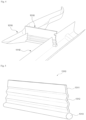
- Fig. 1 is a view showing a tire with a resonator for noise reduction according to the embodiment of the present invention.
- a tire 1000 with a resonator for noise reduction includes a main groove unit 1100, a resonance unit 1200, a neck unit 1300, and a kerf unit 1400.
- the main groove unit 1100 is composed of a plurality of main grooves formed to extend along a circumferential direction of the tire, and the main groove unit 1100 includes a first main groove 1110, a second main groove 1120, a third main groove 1130 and a fourth main groove 1140.
- the first main groove 1110, the second main groove 1120, the third main groove 1130, and the fourth main groove 1140 are sequentially formed from the outside of the vehicle.
- the first main groove 1110 is a main groove located at the outermost side in a state where the tire is mounted on the vehicle.
- Fig. 2 is a view showing a first resonance unit, the first main groove, a first neck unit, and a first kerf unit according to the embodiment of the present invention.
- Fig. 3 is a design view showing the first resonance unit according to the embodiment of the present invention.
- Fig. 4 is a perspective view showing the first resonance unit, the first main groove, and the first neck unit according to the embodiment of the present invention.
- the resonance unit 1200 is formed on a mid-rib formed between a pair of the main grooves, and may be formed of a Helmholtz resonator.
- the resonance unit 1200 is formed between a pair of the main grooves among the first main groove 1110, the second main groove 1120, the third main groove 1130, and the fourth main groove 1140.
- the resonance unit 1200 includes a first resonance unit 1210 and a second resonance unit 1220.
- the first resonance unit 1210 is provided between the first main groove 1110 and the second main groove 1120.
- the second resonance unit 1220 is provided between the third main groove 1130 and the fourth main groove 1140.
- the volumes of the first resonance unit 1210 and the second resonance unit 1220 may be 500 mm 3 to 1,500 mm 3 .
- the resonance unit 1200 may be provided at every predetermined interval along the circumferential direction of the tire.
- the resonance unit 1200 may be formed every two pitches in the circumferential direction of the tire.
- the depth of the resonance unit 1200 may include the entire height of the neck unit 1300, the resonance unit 1200 may be located within an angle of 30 degrees to 90 degrees based on the main groove unit 1100.
- the resonance unit 1200 may further include a third resonance unit provided between the second main groove 1120 and the third main groove 1130.
- the neck unit 1300 is provided to communicate the resonance unit 1200 with one of the pair of the main grooves, and includes a first neck unit 1310 and a second neck unit 1320.
- Fig. 5 is a perspective view showing the first neck unit according to the embodiment of the present invention.
- Fig. 6 is a design view showing the first neck unit according to the embodiment of the present invention.
- Fig. 7 is a view showing before and after applying a load to the first neck unit in accordance with the embodiment of the present invention.
- Fig. 8 is a design view showing the second resonance unit according to the embodiment of the present invention.
- Fig. 9 is a perspective view showing the second resonance unit, the third main groove, and the second neck unit according to the embodiment of the present invention.
- the first neck unit 1310 is provided to connect the first resonance unit 1210 and the first main groove 1110, and includes a straight flow path 1311, a curved flow path 1312, and a neck 1313.
- the straight flow path 1311 is formed to extend between the first resonance unit 1210 and the first main groove 1110. Also, the straight flow path 1311 is provided to have a predetermined depth toward the bottom thereof may be formed to extend in a straight line shape in the depth direction.
- the curved flow path 1312 may extend toward the bottom of the straight flow path 1311 and may be formed in zigzags or in a wavy shape having a predetermined radius.
- the neck 1313 is formed under the curved flow path 1312 and has a cylindrical shape.
- the neck 1313 extends such that the first resonance unit 1210 and the first main groove 1110 communicate with each other.
- the straight flow path 1311 and the curved flow path 1312 provided as described above are formed in an interlocking structure and closed when they contact the ground and a load is applied. That is, when the straight flow path 1311 and the curved flow path 1312 contact the ground, they perform a function of discharging internal water to the outside of the tire while being closed.
- the neck 1313 is formed to maintain a state where the first main groove 1110 and the first resonance unit 1210 are in communication with each other even when receiving a load.
- the neck 1313 is provided to reduce pipe resonance noise by communicating air within the first main groove 1110 and air within the first resonance unit 1210.
- the first resonator 1210 capable of serving as a Helmholtz resonator is provided between the first main grooves 1110 and is connected to the first main groove 1110 through the neck 1313.
- the pipe resonance noise generated in the first main groove 1110 is transmitted to the first resonance unit 1210 through the neck 1313, and the pipe resonance transmitted to the first resonance unit 1210 generates resonance. That is, the flow is performed rapidly through the neck 1313 which connects the first main groove 1110 and the first resonance unit 1210.
- noise energy is reduced by Visco-thermal effects that is a noise attenuation mechanism.
- the neck 1313 connecting the first main groove 1110 and the first resonance unit 1210 is inserted inside the surface of the tire, so that noise which is generated when the neck 1313 is exposed on the surface of the tire is minimized.
- a 3D-kerf shape is applied through the straight flow path 1311 and the curved flow path 1312 when inserting the neck 1313 into the inside of the surface of the tire, so that friction sound between blocks and air pumping noise during tire rotation.
- the length of the first neck unit 1310 provided as described above may be formed to be 5 mm to 20 mm.
- the diameter of the neck 1313 may be determined by a distance between the first main groove 1110 and the second main groove 1120 and the volume of the first resonance unit 1210.
- the neck 1313 may have a diameter of 1 mm to 3 mm and may have a cross-sectional area of 1 mm 2 to 12 mm 2 .
- the second neck unit 1320 is provided to connect the second resonance unit 1220 and the third main groove 1130.
- the second neck unit 1320 includes a straight flow path, a curved flow path, and a neck. Since the configuration thereof is substantially the same as that of the first neck unit 1310, a detailed description thereof will be omitted.
- the kerf unit 1400 is provided to connect the resonance unit 1200 and the other of the pair of main grooves.
- the kerf unit 1400 includes a first kerf unit 1410 and a second kerf unit 1420.
- the first kerf unit 1410 is provided to connect the first resonance unit 1210 and the second main groove 1120
- the second kerf unit 1420 is provided to connect the second resonance unit 1220 and the fourth main groove 1140.
- the first kerf unit 1410 is formed of a straight flow path and a curved flow path.
- the straight flow path of the first kerf unit 1410 is formed to extend between the first resonance portion 1210 and the second main groove 1120.
- the straight flow path may be provided to have a predetermined depth toward the bottom thereof may be formed to extend in a straight line shape in the depth direction.
- the curved flow path is formed to extend toward the bottom of the straight flow path and to have a predetermined radius.
- the curved flow path may extend toward the bottom of the straight flow path and may be formed in zigzags or in a wavy shape having a predetermined radius.
- the straight flow path and the curved flow path provided as described above may be formed in an interlocking structure and may be closed when they contact the ground and a load is applied. That is, when the straight flow path and the curved flow path contact the ground, they may be provided to perform a function of discharging internal water to the outside of the tire while being closed.
- the kerf unit 1400 may be provided to have a depth of less than 1 mm.
- first kerf unit 1410 and the second kerf unit 1420 are provided to include an image kerf of which a depth is smaller than those of the straight flow path and the curved flow path.
- first kerf unit 1410 and the second kerf unit 1420 may further include additional image kerfs in addition to the straight flow path and the curved flow path, and may include the image kerf instead of the straight flow path and the curved flow path.
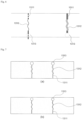
- Fig. 10 is a graph showing a magnitude of the pipe resonance noise according to a frequency band.
- the tire has a tubular shape when the main groove contacts the ground. Due to this tubular shape, noise is generated by the pipe resonance noise. This is related to the size of the tire and a ground field on the ground, and the noise has, as shown in Fig. 10 , a band of about 800 to 1200 Hz. This has a great influence on the overall tire rolling noise.
- Fig. 11 is a graph showing the pipe resonance noise of a conventional example and the embodiment of the present invention.
- a verification experiment was performed by using a mock-up according to the present invention in order to verify the pipe resonance noise reduction effect according to the present invention.
- the mock-up was used in the verification experiment, and a Q-source that is an air volume shaker, and a microphone for noise measurement were used.
- the frequency response function between the Q-source and the mock-up is measured, and a smooth main groove shape of a general tire and the Helmholtz resonator of the present invention are manufactured as a mock-up and are used for verification of the pipe resonance reduction.
- Fig. 11 shows the result.
- the graph of the conventional example shows a simple main groove
- the graph of the embodiment of the present invention shows a signal from the main groove unit 1100 to which the Helmholtz resonator of the present invention is applied.
- the neck 1313 is exposed on the surface of the tire at the end of wear, it can contribute to anti-slip performance due to increase in void.
- main groove unit 1110 first main groove 1120: second main groove 1130: third main groove 1140: fourth main groove 1200: resonance unit 1210: first resonance unit 1220: second resonance unit 1300: neck unit 1310: first neck unit 1311: straight flow path 1312: curved flow path 1313: neck 1320: second neck unit 1400: kerf unit 1410: first kerf unit 1420: second kerf unit
Landscapes
- Engineering & Computer Science (AREA)
- Mechanical Engineering (AREA)
- Physics & Mathematics (AREA)
- Acoustics & Sound (AREA)
- Multimedia (AREA)
- Tires In General (AREA)
Description
- The present invention relates to a tire with a resonator for noise reduction and more particularly to a tire with a resonator which reduces noise by reducing noise energy generated in main grooves.
- A vehicle which goes forward by rolling wheels is inherently has no choice but to make noise. However, noise such as engine sound coming from inside and outside the vehicle, wind noise (sound of wind), etc., while driving, always annoys the driver and passengers. For this reason, it is common to block the noise by using a soundproofing material, a sound-absorbing material, etc.
- However, the Ministry of Environment has recently announced that it will introduce "tire noise insulation performance indication system" which is being carried out in European Union (EU) from 2019. In response to this, technology developments to reduce noise are being made ahead of enforcement of the system. Particularly, while, in the past, the focus was on reducing the generation of noise inside the vehicle such as the engine, there are increasing cases of applying a new low noise technology from the early stage of tire product development in order to minimize the noise generated outside the vehicle such as from a tire.
- In particular, tires for electric vehicles, whose market share is rapidly increasing in recent years, are required to have noise characteristics different from those of an Internal Combustion Engine (ICE) vehicle.
- For example, in the case of an ICE vehicle, the noise from the engine causes the largest noise over the entire range of indoor noise. However, since the electric vehicle does not have an engine, it has an overall low noise level and the largest noise generated from the tire. Therefore, recently, a low noise tire becomes gradually more important.
- A peak due to pipe resonance occurs in a range of 1 kHz in tire noise, and the resulting effect occupies a very large proportion of the overall noise. Specifically, when the main groove in the traveling direction of the tire contacts the ground, the ground and the main groove form a pipe shape. Here, pipe resonance noise in a 1 kHz band is generated due to pipe-shaped flow inside the main groove.
- Therefore, there is a necessity of a technology for reducing the pipe resonance noise generated in the main groove of the tire.
- (Patent Document 1)
Korean Patent No. 10-1957640 -
WO 2019/117091 A1 describes a tire having a plurality of land sections on a tread surface, the land sections being divided on at least one side in the tire width direction by a circumferential main groove that extends and continues in the tire circumferential direction. The tire is provided with inner resonators that include, in inner land sections that are positioned in an inner half section when mounted on a vehicle with respect to the tire equatorial surface among the plurality of land sections. -
EP 2 962 872 A1 -
EP 3 118 020 A1 describes a pneumatic tire that includes: two external circumferential main grooves in a vehicle-installed outside half portion; two internal circumferential main grooves in a vehicle-installed inside half portion; a central land portion; an external intermediate land portion; and an internal intermediate land portion. - The purpose of the present invention to solve the aforementioned problems is to provide a tire with a resonator which reduces noise by reducing noise energy generated in main grooves.
- The technical problem to be overcome in this document is not limited to the above-mentioned technical problems. Other technical problems not mentioned can be clearly understood from those described below by a person having ordinary skill in the art.
- The invention provides a tire with a resonator for noise reduction as defined in
claim 1, which includes: a main groove unit which has a plurality of main grooves formed to extend along a circumferential direction of the tire; a resonance unit which is formed between a pair of the main grooves; a neck unit which is provided to communicate the resonance unit with one of the pair of main grooves; and a kerf unit which is provided to connect the resonance unit and the other of the pair of main grooves. - According to an embodiment of the present invention, the resonance unit is composed of a Helmholtz resonator.
- According to an embodiment of the present invention, volumes of the first resonance unit and the second resonance unit are 500 mm3 to 1,500 mm3.
- According to an embodiment of the present invention, a length of the first neck unit is formed to be 5 mm to 20 mm.
- According to an embodiment of the present invention, a diameter of the neck is determined by a distance between the first main groove and the second main groove and a volume of the first resonance unit.
- According to an embodiment of the present invention, the diameter of the neck is 1 mm to 3 mm and a cross-sectional area of the neck is 1 mm2 to 12 mm2.
- According to an embodiment of the present invention, the second kerf unit includes:
a straight flow path which is formed to extend between the second resonance unit and the fourth main groove; and a curved flow path which is formed to extend toward a bottom of the straight flow path and to have a predetermined radius. - According to an embodiment of the present invention, the resonance unit further includes a third resonance unit which is provided between the second main groove and the third main groove.
- According to an embodiment of the present invention, the first kerf unit and the second kerf unit are provided to include an image kerf of which a depth is smaller than those of the straight flow path and the curved flow path.
- The present invention allows to reduce the pipe resonance noise generated in the main groove.
- Specifically, the resonance unit capable of serving as a Helmholtz resonator is provided between the main grooves and is connected with the main groove through the neck unit. The pipe resonance noise generated in the main groove is transmitted to the resonance unit through the neck unit. The pipe resonance transmitted to the resonance unit generates resonance. As a result, the flow enters and exits rapidly through the neck unit which connects the main groove and the resonance unit. Here, noise energy is reduced by Visco-thermal effects that is a noise attenuation mechanism.
- Also, in the case of another company's pattern in which the neck unit of the resonance unit is on the surface of the tire, new noise may be caused when it contacts the ground. However, according to the embodiment of the present invention, the neck unit connecting the main groove and the resonance unit is inserted inside the surface of the tire, so that the noise which is generated when the neck unit is exposed on the surface of the tire is minimized.
- Also, a 3D-kerf shape is applied when inserting the neck inside the surface, so that it is possible to reduce friction sound between blocks and air pumping noise during tire rotation.
- The effect of the described embodiments is not limited to the above effects and should be construed as including all the effects that can be inferred from the configuration of the embodiments disclosed in the detailed description or claims.
-
-
Fig. 1 is a view showing a tire with a resonator for noise reduction according to an embodiment of the present invention; -
Fig. 2 is a view showing a first resonance unit, a first main groove, a first neck unit, and a first kerf unit according to the embodiment of the present invention; -
Fig. 3 is a design view showing the first resonance unit according to the embodiment of the present invention; -
Fig. 4 is a perspective view showing the first resonance unit, the first main groove, and the first neck unit according to the embodiment of the present invention; -
Fig. 5 is a perspective view showing the first neck unit according to the embodiment of the present invention; -
Fig. 6 is a design view showing the first neck unit according to the embodiment of the present invention; -
Fig. 7 is a view showing before and after applying a load to the first neck unit in accordance with the embodiment of the present invention; -
Fig. 8 is a design view showing a second resonance unit according to the embodiment of the present invention; -
Fig. 9 is a perspective view showing the second resonance unit, a third main groove, and a second neck unit according to the embodiment of the present invention; -
Fig. 10 is a graph showing a magnitude of pipe resonance noise according to a frequency band; and -
Fig. 11 is a graph showing the pipe resonance noise of a conventional example and the embodiment of the present invention. - Hereinafter, the invention will be described with reference to the accompanying drawings. However, the invention may be embodied in various forms and is not limited to the embodiment described in the present specification. In the drawings, parts irrelevant to the description will be omitted for a clear description of the embodiments of the invention. Similar reference numerals will be assigned to similar parts throughout this patent document.
- Throughout the specification, when it is mentioned that a portion is "connected (accessed, contacted, combined)" to another portion, it includes not only "is directly connected" but also "indirectly connected" with another member placed therebetween. Additionally, when it is mentioned that a portion "includes" a component, it means that the portion does not exclude but further includes other components unless there is a special opposite mention.
- Terms used in the present specification are provided for description of only specific embodiments of the present invention, and not intended to be limiting. An expression of a singular form includes the expression of plural form thereof unless otherwise explicitly mentioned in the context. In the present specification, it should be understood that the term "include" or "comprise" and the like is intended to specify characteristics, numbers, steps, operations, components, parts or any combination thereof which are mentioned in the specification, and intended not to previously exclude the possibility of existence or addition of at least one another characteristics, numbers, steps, operations, components, parts or any combination thereof.
- Hereinafter, the embodiments of the present invention will be described in detail with reference to the accompanying drawings.
-
Fig. 1 is a view showing a tire with a resonator for noise reduction according to the embodiment of the present invention. - As shown in
Fig. 1 , atire 1000 with a resonator for noise reduction includes amain groove unit 1100, aresonance unit 1200, aneck unit 1300, and akerf unit 1400. - The
main groove unit 1100 is composed of a plurality of main grooves formed to extend along a circumferential direction of the tire, and themain groove unit 1100 includes a firstmain groove 1110, a secondmain groove 1120, a thirdmain groove 1130 and a fourthmain groove 1140. - The first
main groove 1110, the secondmain groove 1120, the thirdmain groove 1130, and the fourthmain groove 1140 are sequentially formed from the outside of the vehicle. - That is, the first
main groove 1110 is a main groove located at the outermost side in a state where the tire is mounted on the vehicle. -
Fig. 2 is a view showing a first resonance unit, the first main groove, a first neck unit, and a first kerf unit according to the embodiment of the present invention.Fig. 3 is a design view showing the first resonance unit according to the embodiment of the present invention.Fig. 4 is a perspective view showing the first resonance unit, the first main groove, and the first neck unit according to the embodiment of the present invention. - With further reference to
Figs 2 to 4 , theresonance unit 1200 is formed on a mid-rib formed between a pair of the main grooves, and may be formed of a Helmholtz resonator. - The
resonance unit 1200 is formed between a pair of the main grooves among the firstmain groove 1110, the secondmain groove 1120, the thirdmain groove 1130, and the fourthmain groove 1140. - Also, the
resonance unit 1200 includes afirst resonance unit 1210 and asecond resonance unit 1220. - The
first resonance unit 1210 is provided between the firstmain groove 1110 and the secondmain groove 1120. - The
second resonance unit 1220 is provided between the thirdmain groove 1130 and the fourthmain groove 1140. - Also, the volumes of the
first resonance unit 1210 and thesecond resonance unit 1220 may be 500 mm3 to 1,500 mm3. - Also, the
resonance unit 1200 may be provided at every predetermined interval along the circumferential direction of the tire. For example, theresonance unit 1200 may be formed every two pitches in the circumferential direction of the tire. - The depth of the
resonance unit 1200 may include the entire height of theneck unit 1300, theresonance unit 1200 may be located within an angle of 30 degrees to 90 degrees based on themain groove unit 1100. - The
resonance unit 1200 may further include a third resonance unit provided between the secondmain groove 1120 and the thirdmain groove 1130. - The
neck unit 1300 is provided to communicate theresonance unit 1200 with one of the pair of the main grooves, and includes afirst neck unit 1310 and asecond neck unit 1320. -
Fig. 5 is a perspective view showing the first neck unit according to the embodiment of the present invention.Fig. 6 is a design view showing the first neck unit according to the embodiment of the present invention.Fig. 7 is a view showing before and after applying a load to the first neck unit in accordance with the embodiment of the present invention. -
Fig. 8 is a design view showing the second resonance unit according to the embodiment of the present invention.Fig. 9 is a perspective view showing the second resonance unit, the third main groove, and the second neck unit according to the embodiment of the present invention. - Referring to
Figs. 5 to 9 , thefirst neck unit 1310 is provided to connect thefirst resonance unit 1210 and the firstmain groove 1110, and includes astraight flow path 1311, acurved flow path 1312, and aneck 1313. - The
straight flow path 1311 is formed to extend between thefirst resonance unit 1210 and the firstmain groove 1110. Also, thestraight flow path 1311 is provided to have a predetermined depth toward the bottom thereof may be formed to extend in a straight line shape in the depth direction. - The
curved flow path 1312 formed to extend toward the bottom of thestraight flow path 1311 and to have a predetermined radius. For example, thecurved flow path 1312 may extend toward the bottom of thestraight flow path 1311 and may be formed in zigzags or in a wavy shape having a predetermined radius. - The
neck 1313 is formed under thecurved flow path 1312 and has a cylindrical shape. Theneck 1313 extends such that thefirst resonance unit 1210 and the firstmain groove 1110 communicate with each other. - The
straight flow path 1311 and thecurved flow path 1312 provided as described above are formed in an interlocking structure and closed when they contact the ground and a load is applied. That is, when thestraight flow path 1311 and thecurved flow path 1312 contact the ground, they perform a function of discharging internal water to the outside of the tire while being closed. - Meanwhile, the
neck 1313 is formed to maintain a state where the firstmain groove 1110 and thefirst resonance unit 1210 are in communication with each other even when receiving a load. Theneck 1313 is provided to reduce pipe resonance noise by communicating air within the firstmain groove 1110 and air within thefirst resonance unit 1210. - Specifically, the
first resonator 1210 capable of serving as a Helmholtz resonator is provided between the firstmain grooves 1110 and is connected to the firstmain groove 1110 through theneck 1313. The pipe resonance noise generated in the firstmain groove 1110 is transmitted to thefirst resonance unit 1210 through theneck 1313, and the pipe resonance transmitted to thefirst resonance unit 1210 generates resonance. That is, the flow is performed rapidly through theneck 1313 which connects the firstmain groove 1110 and thefirst resonance unit 1210. Here, noise energy is reduced by Visco-thermal effects that is a noise attenuation mechanism. - Also, when the
first resonance unit 1210 and theneck 1313 are on the surface of the tire, new noise may be caused when they contact the ground. However, according to the embodiment of the present invention, theneck 1313 connecting the firstmain groove 1110 and thefirst resonance unit 1210 is inserted inside the surface of the tire, so that noise which is generated when theneck 1313 is exposed on the surface of the tire is minimized. - According to the embodiment of the present invention, a 3D-kerf shape is applied through the
straight flow path 1311 and thecurved flow path 1312 when inserting theneck 1313 into the inside of the surface of the tire, so that friction sound between blocks and air pumping noise during tire rotation. - The length of the
first neck unit 1310 provided as described above may be formed to be 5 mm to 20 mm. - Also, the diameter of the
neck 1313 may be determined by a distance between the firstmain groove 1110 and the secondmain groove 1120 and the volume of thefirst resonance unit 1210. - More specifically, the
neck 1313 may have a diameter of 1 mm to 3 mm and may have a cross-sectional area of 1 mm2 to 12 mm2. - The
second neck unit 1320 is provided to connect thesecond resonance unit 1220 and the thirdmain groove 1130. - The
second neck unit 1320 includes a straight flow path, a curved flow path, and a neck. Since the configuration thereof is substantially the same as that of thefirst neck unit 1310, a detailed description thereof will be omitted. - The
kerf unit 1400 is provided to connect theresonance unit 1200 and the other of the pair of main grooves. - Specifically, the
kerf unit 1400 includes afirst kerf unit 1410 and asecond kerf unit 1420. - The
first kerf unit 1410 is provided to connect thefirst resonance unit 1210 and the secondmain groove 1120, and thesecond kerf unit 1420 is provided to connect thesecond resonance unit 1220 and the fourthmain groove 1140. - The
first kerf unit 1410 is formed of a straight flow path and a curved flow path. - Specifically, the straight flow path of the
first kerf unit 1410 is formed to extend between thefirst resonance portion 1210 and the secondmain groove 1120. Also, the straight flow path may be provided to have a predetermined depth toward the bottom thereof may be formed to extend in a straight line shape in the depth direction. - The curved flow path is formed to extend toward the bottom of the straight flow path and to have a predetermined radius. For example, the curved flow path may extend toward the bottom of the straight flow path and may be formed in zigzags or in a wavy shape having a predetermined radius.
- The straight flow path and the curved flow path provided as described above may be formed in an interlocking structure and may be closed when they contact the ground and a load is applied. That is, when the straight flow path and the curved flow path contact the ground, they may be provided to perform a function of discharging internal water to the outside of the tire while being closed.
- Also, the
kerf unit 1400 may be provided to have a depth of less than 1 mm. - Also, the
first kerf unit 1410 and thesecond kerf unit 1420 are provided to include an image kerf of which a depth is smaller than those of the straight flow path and the curved flow path. - More specifically, the
first kerf unit 1410 and thesecond kerf unit 1420 may further include additional image kerfs in addition to the straight flow path and the curved flow path, and may include the image kerf instead of the straight flow path and the curved flow path. -
Fig. 10 is a graph showing a magnitude of the pipe resonance noise according to a frequency band. - Referring to
Fig. 10 , the tire has a tubular shape when the main groove contacts the ground. Due to this tubular shape, noise is generated by the pipe resonance noise. This is related to the size of the tire and a ground field on the ground, and the noise has, as shown inFig. 10 , a band of about 800 to 1200 Hz. This has a great influence on the overall tire rolling noise. -
Fig. 11 is a graph showing the pipe resonance noise of a conventional example and the embodiment of the present invention. - Referring to
Fig. 11 , a verification experiment was performed by using a mock-up according to the present invention in order to verify the pipe resonance noise reduction effect according to the present invention. - The mock-up was used in the verification experiment, and a Q-source that is an air volume shaker, and a microphone for noise measurement were used. The frequency response function between the Q-source and the mock-up is measured, and a smooth main groove shape of a general tire and the Helmholtz resonator of the present invention are manufactured as a mock-up and are used for verification of the pipe resonance reduction.
Fig. 11 shows the result. The graph of the conventional example shows a simple main groove, and the graph of the embodiment of the present invention shows a signal from themain groove unit 1100 to which the Helmholtz resonator of the present invention is applied. As a result of the verification experiment, as shown in the graph, it can be seen that the peak point of the pipe resonance has been significantly reduced, and it can be found that RMS value in a band of 900 Hz to 1250 Hz which is a pipe resonance noise band has been reduced by about 5.9 dB, that is to say, from 106.85 dB to 100.95 dB. - As described above, according to the embodiment of the present invention, it is possible to reduce the pipe resonance noise generated in the
main groove unit 1100. - Also, since the
neck 1313 is exposed on the surface of the tire at the end of wear, it can contribute to anti-slip performance due to increase in void. -
1000: tire with a resonator for noise reduction 1100: main groove unit 1110: first main groove 1120: second main groove 1130: third main groove 1140: fourth main groove 1200: resonance unit 1210: first resonance unit 1220: second resonance unit 1300: neck unit 1310: first neck unit 1311: straight flow path 1312: curved flow path 1313: neck 1320: second neck unit 1400: kerf unit 1410: first kerf unit 1420: second kerf unit
Claims (8)
- A tire (1000) with a resonator for noise reduction, the tire (1000) comprising:a main groove unit (1100) which has a plurality of main grooves (1110, 1120, 1130, 1140) formed to extend along a circumferential direction of the tire (1000);a resonance unit (1200) which is formed between a pair of the main grooves (1110, 1120, 1130, 1140);a neck unit (1300) which is provided to communicate the resonance unit (1200) with one of the pair of main grooves (1110, 1130); anda kerf unit (1400) which is provided to connect the resonance unit (1200) and the otherone of the pair of main grooves (1120, 1140),wherein the main groove unit (1100) includes a first main groove (1110), a second main groove (1120), a third main groove (1130), and a fourth main groove (1140), which are formed separately from each other and sequentially from the outermost sideof the tire when the tire is mounted on a vehicle,wherein the resonance unit (1200) comprises a first resonance unit (1210) provided between the first main groove (1110) and the second main groove (1120); and a second resonance unit (1220) provided between the third main groove (1130) and the fourth main groove (1140),wherein the neck unit (1300) comprises a first neck unit (1310) provided to connect the first resonance unit (1210) and the first main groove (1110); and a second neck unit (1320) provided to connect the second resonance unit (1220) and the third main groove (1130),wherein the first neck unit (1310) comprises a straight flow path (1311) which is formed to extend between the first resonance unit (1210) and the first main groove (1110); a curved flow path (1312) which is formed to extend toward a bottom of the straight flow path (1311) and to have a predetermined radius; and a cylindrical neck (1313) which is formed under the curved flow path (1312),wherein the straight flow path (1311) and the curved flow path (1312) of the first neck unit (1310) are formed in an interlocking structure and are closed when receiving a load,wherein the cylindrical neck (1313) is formed to maintain the state where the first main groove (1110) and the first resonance unit (1210) are in communication with each other even when receiving a load,
andwherein the cylindrical neck (1313) is provided to reduce pipe resonance noise by communicating air within the first main groove (1110) and air within the first resonance unit (1210).wherein the second neck unit (1320) comprises a straight flow path which is formed to extend between the second resonance unit (1220) and the third main groove (1130); a curved flow path which is formed to extend toward a bottom of the straight flow path and to have a predetermined radius; and a cylindrical neck which is formed under the curved flow path,wherein the straight flow path and the curved flow path of the second neck unit (1320) are formed in an interlocking
structure and are closed when receiving a load,wherein the cylindrical neck of the second neck unit (1320)
is formed to maintain the state where the third main groove
(1130) and the second resonance unit (1220) are in communication with each other even when receiving a load,wherein the cylindrical neck of the second neck unit (1320)
is provided to reduce pipe resonance noise by
communicating air within the third main groove (1130) and air within the second resonance unit (1220),wherein the kerf unit (1400) comprises: a first kerf unit (1410) which is provided to connect the first resonance unit (1210) and the second main groove (1120); and a second kerf unit (1420) which is provided to connect the second resonance unit (1220) and the fourth main groove (1140),wherein the first kerf unit (1410) comprises a straight flow path which is formed to extend between the first resonance unit (1210) and the second main groove (1120); and a curved flow path which is formed to extend toward a bottom of the straight flow path and to have a predetermined radius. - The tire (1000) of claim 1, wherein the resonance unit (1200) is composed of a Helmholtz resonator.
- The tire (1000) of claim 1, wherein volumes of the first resonance unit (1210) and the second resonance unit (1220) are 500 mm3 to 1,500 mm3.
- The tire (1000) of claim 1, wherein a length of the first neck unit (1310) is formed to be 5 mm to 20 mm.
- The tire (1000) of claim 1, wherein the diameter of the cylindrical neck (1313) is 1 mm to 3 mm and a cross-sectional area of the cylindrical neck (1313) is 1 mm2 to 12 mm2.
- The tire (1000) of claim 1, wherein the second kerf unit (1420) comprises:a straight flow path which is formed to extend between the second resonance unit (1220) and the fourth main groove (1140); anda curved flow path which is formed to extend toward a bottom of the straight flow path and to have a predetermined radius.
- The tire (1000) of claim 1, wherein the resonance unit (1200) further comprises a third resonance unit which is provided between the second main groove (1120) and the third main groove (1130).
- The tire (1000) of claim 1, wherein the first kerf unit (1410) and the second kerf unit (1420) are provided to include an image kerf of which a depth is smaller than those of the straight flow path and the curved flow path.
Applications Claiming Priority (1)
| Application Number | Priority Date | Filing Date | Title |
|---|---|---|---|
| KR1020190143894A KR102267902B1 (en) | 2019-11-12 | 2019-11-12 | Tires with resonators for noise reduction |
Publications (2)
| Publication Number | Publication Date |
|---|---|
| EP3858642A1 EP3858642A1 (en) | 2021-08-04 |
| EP3858642B1 true EP3858642B1 (en) | 2025-06-11 |
Family
ID=73343953
Family Applications (1)
| Application Number | Title | Priority Date | Filing Date |
|---|---|---|---|
| EP20206988.6A Active EP3858642B1 (en) | 2019-11-12 | 2020-11-11 | Tire with resonators for noise reduction |
Country Status (8)
| Country | Link |
|---|---|
| US (1) | US11794527B2 (en) |
| EP (1) | EP3858642B1 (en) |
| JP (1) | JP7168631B2 (en) |
| KR (1) | KR102267902B1 (en) |
| CN (1) | CN112848811B (en) |
| AU (1) | AU2020267251B2 (en) |
| CA (1) | CA3098549C (en) |
| RU (1) | RU2750647C1 (en) |
Families Citing this family (3)
| Publication number | Priority date | Publication date | Assignee | Title |
|---|---|---|---|---|
| JPWO2023105877A1 (en) * | 2021-12-10 | 2023-06-15 | ||
| CN116665631B (en) * | 2023-05-23 | 2026-01-30 | 哈尔滨理工大学 | A composite silencer with multiple slits connecting a Helmholtz resonant cavity |
| KR102857788B1 (en) * | 2023-07-18 | 2025-09-09 | 한국타이어앤테크놀로지 주식회사 | Pneumatic tire for noise reduction |
Family Cites Families (26)
| Publication number | Priority date | Publication date | Assignee | Title |
|---|---|---|---|---|
| JPH01101205A (en) * | 1987-10-12 | 1989-04-19 | Bridgestone Corp | Pneumatic tire |
| JP2001063323A (en) * | 1999-08-26 | 2001-03-13 | Yokohama Rubber Co Ltd:The | Pneumatic tire |
| JP2006341816A (en) * | 2005-06-10 | 2006-12-21 | Bridgestone Corp | Pneumatic tire |
| JP5013731B2 (en) * | 2006-03-31 | 2012-08-29 | 株式会社ブリヂストン | Pneumatic tire |
| JP5366539B2 (en) * | 2006-03-31 | 2013-12-11 | 株式会社ブリヂストン | Pneumatic tire |
| JP2009001206A (en) * | 2007-06-22 | 2009-01-08 | Bridgestone Corp | Pneumatic tire |
| JP4939969B2 (en) * | 2007-02-19 | 2012-05-30 | 株式会社ブリヂストン | Pneumatic tire |
| JP2008308131A (en) | 2007-06-18 | 2008-12-25 | Bridgestone Corp | Pneumatic tire |
| JP5134879B2 (en) * | 2007-07-30 | 2013-01-30 | 株式会社ブリヂストン | Pneumatic tire |
| JP5160870B2 (en) * | 2007-12-10 | 2013-03-13 | 東洋ゴム工業株式会社 | Pneumatic tire |
| FR2926037B1 (en) * | 2008-01-09 | 2009-12-18 | Michelin Soc Tech | DEVICE FOR ROLLING BAND. |
| JP5350874B2 (en) * | 2009-04-30 | 2013-11-27 | 株式会社ブリヂストン | Pneumatic tire |
| JP4521473B1 (en) * | 2009-05-29 | 2010-08-11 | 株式会社ブリヂストン | tire |
| JP2010280266A (en) * | 2009-06-03 | 2010-12-16 | Bridgestone Corp | Tire |
| KR101042309B1 (en) * | 2009-12-02 | 2011-06-17 | 한국타이어 주식회사 | Groove pattern structure of tire tread for noise reduction |
| JP6076127B2 (en) * | 2013-02-20 | 2017-02-08 | 株式会社ブリヂストン | Pneumatic tire |
| JP6166913B2 (en) * | 2013-02-28 | 2017-07-19 | 株式会社ブリヂストン | Pneumatic tire |
| JP5507735B1 (en) * | 2013-04-25 | 2014-05-28 | 株式会社ブリヂストン | Pneumatic tire |
| JP6124667B2 (en) * | 2013-04-25 | 2017-05-10 | 東洋ゴム工業株式会社 | Pneumatic tire |
| JP5809305B2 (en) * | 2014-03-11 | 2015-11-10 | 株式会社ブリヂストン | Pneumatic tire |
| JP2015214303A (en) * | 2014-05-13 | 2015-12-03 | 株式会社ブリヂストン | tire |
| KR101801932B1 (en) * | 2016-02-22 | 2017-12-28 | 한국타이어 주식회사 | Tire having acoustic absorbent and method for manufacturing the same |
| JP6851858B2 (en) * | 2017-03-02 | 2021-03-31 | 株式会社ブリヂストン | tire |
| EP3725556B1 (en) * | 2017-12-13 | 2023-09-06 | Bridgestone Corporation | Pneumatic tire |
| KR101957640B1 (en) | 2018-08-13 | 2019-03-12 | 한국타이어 주식회사 | Noise reduction tire |
| JP7091232B2 (en) * | 2018-11-27 | 2022-06-27 | 株式会社ブリヂストン | tire |
-
2019
- 2019-11-12 KR KR1020190143894A patent/KR102267902B1/en active Active
-
2020
- 2020-11-09 CA CA3098549A patent/CA3098549C/en active Active
- 2020-11-10 US US17/094,367 patent/US11794527B2/en active Active
- 2020-11-11 EP EP20206988.6A patent/EP3858642B1/en active Active
- 2020-11-11 RU RU2020136947A patent/RU2750647C1/en active
- 2020-11-12 JP JP2020188668A patent/JP7168631B2/en active Active
- 2020-11-12 AU AU2020267251A patent/AU2020267251B2/en active Active
- 2020-11-12 CN CN202011264307.4A patent/CN112848811B/en active Active
Also Published As
| Publication number | Publication date |
|---|---|
| KR20210057840A (en) | 2021-05-24 |
| AU2020267251A1 (en) | 2021-05-27 |
| CA3098549A1 (en) | 2021-05-12 |
| CN112848811A (en) | 2021-05-28 |
| KR102267902B1 (en) | 2021-06-24 |
| US11794527B2 (en) | 2023-10-24 |
| AU2020267251B2 (en) | 2022-11-17 |
| RU2750647C1 (en) | 2021-06-30 |
| EP3858642A1 (en) | 2021-08-04 |
| JP7168631B2 (en) | 2022-11-09 |
| CA3098549C (en) | 2023-09-26 |
| US20210138841A1 (en) | 2021-05-13 |
| CN112848811B (en) | 2023-03-10 |
| JP2021075274A (en) | 2021-05-20 |
Similar Documents
| Publication | Publication Date | Title |
|---|---|---|
| EP2154008B1 (en) | Pneumatic tire | |
| AU2020267251B2 (en) | Tires with resonators for noise reduction | |
| EP2990228B1 (en) | Pneumatic tire | |
| AU2020267241B2 (en) | Tire with noise-reducing main grooves | |
| EP3081392B1 (en) | Tire | |
| JP4976214B2 (en) | Pneumatic tire | |
| EP3127714B1 (en) | Tire | |
| JP5134879B2 (en) | Pneumatic tire | |
| JP2799137B2 (en) | Pneumatic tire | |
| CN101437697B (en) | Pneumatic tire | |
| JP2008308131A (en) | Pneumatic tire | |
| JP2009029259A (en) | Pneumatic tire | |
| JP2008302898A (en) | Pneumatic tire | |
| JP5350854B2 (en) | Pneumatic tire | |
| JP5250219B2 (en) | Pneumatic tire | |
| JP2008290683A (en) | Pneumatic tire | |
| JP2002096608A (en) | Pneumatic tire | |
| KR20250012975A (en) | Pneumatic tire for noise reduction |
Legal Events
| Date | Code | Title | Description |
|---|---|---|---|
| PUAI | Public reference made under article 153(3) epc to a published international application that has entered the european phase |
Free format text: ORIGINAL CODE: 0009012 |
|
| STAA | Information on the status of an ep patent application or granted ep patent |
Free format text: STATUS: REQUEST FOR EXAMINATION WAS MADE |
|
| 17P | Request for examination filed |
Effective date: 20201111 |
|
| AK | Designated contracting states |
Kind code of ref document: A1 Designated state(s): AL AT BE BG CH CY CZ DE DK EE ES FI FR GB GR HR HU IE IS IT LI LT LU LV MC MK MT NL NO PL PT RO RS SE SI SK SM TR |
|
| STAA | Information on the status of an ep patent application or granted ep patent |
Free format text: STATUS: EXAMINATION IS IN PROGRESS |
|
| 17Q | First examination report despatched |
Effective date: 20230404 |
|
| GRAP | Despatch of communication of intention to grant a patent |
Free format text: ORIGINAL CODE: EPIDOSNIGR1 |
|
| STAA | Information on the status of an ep patent application or granted ep patent |
Free format text: STATUS: GRANT OF PATENT IS INTENDED |
|
| GRAJ | Information related to disapproval of communication of intention to grant by the applicant or resumption of examination proceedings by the epo deleted |
Free format text: ORIGINAL CODE: EPIDOSDIGR1 |
|
| STAA | Information on the status of an ep patent application or granted ep patent |
Free format text: STATUS: EXAMINATION IS IN PROGRESS |
|
| INTG | Intention to grant announced |
Effective date: 20241108 |
|
| INTC | Intention to grant announced (deleted) | ||
| GRAP | Despatch of communication of intention to grant a patent |
Free format text: ORIGINAL CODE: EPIDOSNIGR1 |
|
| STAA | Information on the status of an ep patent application or granted ep patent |
Free format text: STATUS: GRANT OF PATENT IS INTENDED |
|
| INTG | Intention to grant announced |
Effective date: 20250110 |
|
| GRAS | Grant fee paid |
Free format text: ORIGINAL CODE: EPIDOSNIGR3 |
|
| GRAA | (expected) grant |
Free format text: ORIGINAL CODE: 0009210 |
|
| STAA | Information on the status of an ep patent application or granted ep patent |
Free format text: STATUS: THE PATENT HAS BEEN GRANTED |
|
| AK | Designated contracting states |
Kind code of ref document: B1 Designated state(s): AL AT BE BG CH CY CZ DE DK EE ES FI FR GB GR HR HU IE IS IT LI LT LU LV MC MK MT NL NO PL PT RO RS SE SI SK SM TR |
|
| REG | Reference to a national code |
Ref country code: GB Ref legal event code: FG4D |
|
| REG | Reference to a national code |
Ref country code: CH Ref legal event code: EP |
|
| REG | Reference to a national code |
Ref country code: IE Ref legal event code: FG4D |
|
| REG | Reference to a national code |
Ref country code: DE Ref legal event code: R096 Ref document number: 602020052557 Country of ref document: DE |
|
| PG25 | Lapsed in a contracting state [announced via postgrant information from national office to epo] |
Ref country code: FI Free format text: LAPSE BECAUSE OF FAILURE TO SUBMIT A TRANSLATION OF THE DESCRIPTION OR TO PAY THE FEE WITHIN THE PRESCRIBED TIME-LIMIT Effective date: 20250611 Ref country code: ES Free format text: LAPSE BECAUSE OF FAILURE TO SUBMIT A TRANSLATION OF THE DESCRIPTION OR TO PAY THE FEE WITHIN THE PRESCRIBED TIME-LIMIT Effective date: 20250611 |
|
| REG | Reference to a national code |
Ref country code: LT Ref legal event code: MG9D |
|
| PG25 | Lapsed in a contracting state [announced via postgrant information from national office to epo] |
Ref country code: GR Free format text: LAPSE BECAUSE OF FAILURE TO SUBMIT A TRANSLATION OF THE DESCRIPTION OR TO PAY THE FEE WITHIN THE PRESCRIBED TIME-LIMIT Effective date: 20250912 Ref country code: NO Free format text: LAPSE BECAUSE OF FAILURE TO SUBMIT A TRANSLATION OF THE DESCRIPTION OR TO PAY THE FEE WITHIN THE PRESCRIBED TIME-LIMIT Effective date: 20250911 |
|
| REG | Reference to a national code |
Ref country code: NL Ref legal event code: MP Effective date: 20250611 |
|
| PG25 | Lapsed in a contracting state [announced via postgrant information from national office to epo] |
Ref country code: BG Free format text: LAPSE BECAUSE OF FAILURE TO SUBMIT A TRANSLATION OF THE DESCRIPTION OR TO PAY THE FEE WITHIN THE PRESCRIBED TIME-LIMIT Effective date: 20250611 |
|
| PG25 | Lapsed in a contracting state [announced via postgrant information from national office to epo] |
Ref country code: HR Free format text: LAPSE BECAUSE OF FAILURE TO SUBMIT A TRANSLATION OF THE DESCRIPTION OR TO PAY THE FEE WITHIN THE PRESCRIBED TIME-LIMIT Effective date: 20250611 |
|
| PG25 | Lapsed in a contracting state [announced via postgrant information from national office to epo] |
Ref country code: RS Free format text: LAPSE BECAUSE OF FAILURE TO SUBMIT A TRANSLATION OF THE DESCRIPTION OR TO PAY THE FEE WITHIN THE PRESCRIBED TIME-LIMIT Effective date: 20250911 |
|
| PG25 | Lapsed in a contracting state [announced via postgrant information from national office to epo] |
Ref country code: LV Free format text: LAPSE BECAUSE OF FAILURE TO SUBMIT A TRANSLATION OF THE DESCRIPTION OR TO PAY THE FEE WITHIN THE PRESCRIBED TIME-LIMIT Effective date: 20250611 |
|
| PG25 | Lapsed in a contracting state [announced via postgrant information from national office to epo] |
Ref country code: NL Free format text: LAPSE BECAUSE OF FAILURE TO SUBMIT A TRANSLATION OF THE DESCRIPTION OR TO PAY THE FEE WITHIN THE PRESCRIBED TIME-LIMIT Effective date: 20250611 |
|
| PG25 | Lapsed in a contracting state [announced via postgrant information from national office to epo] |
Ref country code: PT Free format text: LAPSE BECAUSE OF FAILURE TO SUBMIT A TRANSLATION OF THE DESCRIPTION OR TO PAY THE FEE WITHIN THE PRESCRIBED TIME-LIMIT Effective date: 20251013 |
|
| REG | Reference to a national code |
Ref country code: AT Ref legal event code: MK05 Ref document number: 1802073 Country of ref document: AT Kind code of ref document: T Effective date: 20250611 |
|
| PG25 | Lapsed in a contracting state [announced via postgrant information from national office to epo] |
Ref country code: IS Free format text: LAPSE BECAUSE OF FAILURE TO SUBMIT A TRANSLATION OF THE DESCRIPTION OR TO PAY THE FEE WITHIN THE PRESCRIBED TIME-LIMIT Effective date: 20251011 |
|
| PGFP | Annual fee paid to national office [announced via postgrant information from national office to epo] |
Ref country code: DE Payment date: 20251020 Year of fee payment: 6 |
|
| PG25 | Lapsed in a contracting state [announced via postgrant information from national office to epo] |
Ref country code: AT Free format text: LAPSE BECAUSE OF FAILURE TO SUBMIT A TRANSLATION OF THE DESCRIPTION OR TO PAY THE FEE WITHIN THE PRESCRIBED TIME-LIMIT Effective date: 20250611 Ref country code: SM Free format text: LAPSE BECAUSE OF FAILURE TO SUBMIT A TRANSLATION OF THE DESCRIPTION OR TO PAY THE FEE WITHIN THE PRESCRIBED TIME-LIMIT Effective date: 20250611 |
|
| PGFP | Annual fee paid to national office [announced via postgrant information from national office to epo] |
Ref country code: FR Payment date: 20251021 Year of fee payment: 6 |
|
| PG25 | Lapsed in a contracting state [announced via postgrant information from national office to epo] |
Ref country code: CZ Free format text: LAPSE BECAUSE OF FAILURE TO SUBMIT A TRANSLATION OF THE DESCRIPTION OR TO PAY THE FEE WITHIN THE PRESCRIBED TIME-LIMIT Effective date: 20250611 |
|
| PG25 | Lapsed in a contracting state [announced via postgrant information from national office to epo] |
Ref country code: PL Free format text: LAPSE BECAUSE OF FAILURE TO SUBMIT A TRANSLATION OF THE DESCRIPTION OR TO PAY THE FEE WITHIN THE PRESCRIBED TIME-LIMIT Effective date: 20250611 |
|
| PG25 | Lapsed in a contracting state [announced via postgrant information from national office to epo] |
Ref country code: EE Free format text: LAPSE BECAUSE OF FAILURE TO SUBMIT A TRANSLATION OF THE DESCRIPTION OR TO PAY THE FEE WITHIN THE PRESCRIBED TIME-LIMIT Effective date: 20250611 |
|
| PG25 | Lapsed in a contracting state [announced via postgrant information from national office to epo] |
Ref country code: SK Free format text: LAPSE BECAUSE OF FAILURE TO SUBMIT A TRANSLATION OF THE DESCRIPTION OR TO PAY THE FEE WITHIN THE PRESCRIBED TIME-LIMIT Effective date: 20250611 Ref country code: RO Free format text: LAPSE BECAUSE OF FAILURE TO SUBMIT A TRANSLATION OF THE DESCRIPTION OR TO PAY THE FEE WITHIN THE PRESCRIBED TIME-LIMIT Effective date: 20250611 |
|
| REG | Reference to a national code |
Ref country code: DE Ref legal event code: R097 Ref document number: 602020052557 Country of ref document: DE |
|
| PG25 | Lapsed in a contracting state [announced via postgrant information from national office to epo] |
Ref country code: DK Free format text: LAPSE BECAUSE OF FAILURE TO SUBMIT A TRANSLATION OF THE DESCRIPTION OR TO PAY THE FEE WITHIN THE PRESCRIBED TIME-LIMIT Effective date: 20250611 |
|
| PG25 | Lapsed in a contracting state [announced via postgrant information from national office to epo] |
Ref country code: IT Free format text: LAPSE BECAUSE OF FAILURE TO SUBMIT A TRANSLATION OF THE DESCRIPTION OR TO PAY THE FEE WITHIN THE PRESCRIBED TIME-LIMIT Effective date: 20250611 |
|
| PLBE | No opposition filed within time limit |
Free format text: ORIGINAL CODE: 0009261 |
|
| STAA | Information on the status of an ep patent application or granted ep patent |
Free format text: STATUS: NO OPPOSITION FILED WITHIN TIME LIMIT |
|
| REG | Reference to a national code |
Ref country code: CH Ref legal event code: L10 Free format text: ST27 STATUS EVENT CODE: U-0-0-L10-L00 (AS PROVIDED BY THE NATIONAL OFFICE) Effective date: 20260423 |