EP3858511A1 - Tool for double-sided incremental formingn and method of using the tool - Google Patents
Tool for double-sided incremental formingn and method of using the tool Download PDFInfo
- Publication number
- EP3858511A1 EP3858511A1 EP21151695.0A EP21151695A EP3858511A1 EP 3858511 A1 EP3858511 A1 EP 3858511A1 EP 21151695 A EP21151695 A EP 21151695A EP 3858511 A1 EP3858511 A1 EP 3858511A1
- Authority
- EP
- European Patent Office
- Prior art keywords
- tool
- sleeve
- contact member
- workpiece
- working tip
- Prior art date
- Legal status (The legal status is an assumption and is not a legal conclusion. Google has not performed a legal analysis and makes no representation as to the accuracy of the status listed.)
- Granted
Links
Images




Classifications
-
- B—PERFORMING OPERATIONS; TRANSPORTING
- B21—MECHANICAL METAL-WORKING WITHOUT ESSENTIALLY REMOVING MATERIAL; PUNCHING METAL
- B21D—WORKING OR PROCESSING OF SHEET METAL OR METAL TUBES, RODS OR PROFILES WITHOUT ESSENTIALLY REMOVING MATERIAL; PUNCHING METAL
- B21D31/00—Other methods for working sheet metal, metal tubes, metal profiles
- B21D31/005—Incremental shaping or bending, e.g. stepwise moving a shaping tool along the surface of the workpiece
-
- B—PERFORMING OPERATIONS; TRANSPORTING
- B21—MECHANICAL METAL-WORKING WITHOUT ESSENTIALLY REMOVING MATERIAL; PUNCHING METAL
- B21D—WORKING OR PROCESSING OF SHEET METAL OR METAL TUBES, RODS OR PROFILES WITHOUT ESSENTIALLY REMOVING MATERIAL; PUNCHING METAL
- B21D37/00—Tools as parts of machines covered by this subclass
- B21D37/10—Die sets; Pillar guides
Definitions
- the present disclosure relates generally to the field of forming tools and, more specifically, to a forming tool that maintains a working tip of the tool against a workpiece during a forming process.
- Double sided incremental forming is a process for forming relatively thin sheets of material, such as sheet metal.
- the process includes two tools each having a tip with one of the tools being a support tool and the other tool being a forming tool.
- the first tool contacts the workpiece on a first side and the second tool contacts the workpiece on an opposing second side.
- the tools move together such that the tips are aligned or offset on the opposing sides of the sheet.
- the two tools move their respective tips along a preprogrammed path to form the workpiece and generate the desired part. Roles of the two tools can be interchanged to form features on both sides of the sheet without any additional setup.
- the accuracy of the forming process is improved when both of the tips are aligned (or offset in a controlled manner) and are maintained in contact with the opposing sides of the sheet.
- the coordinated motion of the two tools can sometimes lead to situations where the contact between the support tool and work piece is lost because of errors originating from assumptions made during simulation, variation in machine stiffness, slight mismatch between predicted and actual sheet thickness at a given point when subjected to deformation, etc. This affects the quality and accuracy of the finished part.
- the tool comprises a sleeve that comprises a first end and a second end and with a hollow interior space that extends into the sleeve from the first end.
- a mount is positioned at the second end of the sleeve.
- a spring is positioned within hollow interior space of the sleeve.
- a contact member comprises a working tip and an opposing end. The opposing end of the contact member is positioned within the interior space of the sleeve and the working tip is positioned outward beyond the sleeve to contact against the workpiece.
- the contact member is biased outward away from the sleeve by the spring.
- Bearing members act on the contact member and provide for rotational and translational movement of the contact member relative to the mount.
- the bearing members comprise a translational bearing mounted to the sleeve and having an opening through which the contact member extends, and the translational bearing comprising a plurality of rollers that contact against the contact member and provide for the translational movement of the contact member relative to the sleeve.
- the bearing members comprise a ball bearing operatively connected to the sleeve to provide for rotation of the sleeve relative to the mount.
- each of the mount, the sleeve, the spring, and the contact member are coaxially aligned along a longitudinal axis of the tool.
- the spring is a coil spring with a helical shape that extends around the opposing end of the contact member.
- the working tip of the contact member comprises a spherical shape.
- one of the bearing members is fixedly mounted within the interior space of the sleeve and remains fixed relative to the sleeve during the translational movement of the contact member within the sleeve.
- a pin extends through the contact member and through the sleeve with the pin configured to move with the contact member relative to the sleeve during the translational movement of the contact member and to prevent the contact member from moving out of the interior space of the sleeve.
- the tool comprises a sleeve with a hollow interior space.
- a mount is connected to the sleeve.
- a contact member is positioned in the interior space of the sleeve with the contact member comprising a working end configured to contact against the workpiece.
- a spring is positioned within hollow interior space of the sleeve to bias the contact member in a direction outward from the interior space to maintain the working end of the contact member in contact with the workpiece.
- a first bearing member is operatively connected to the contact member and provides translational movement of the contact member relative to the mount.
- a second bearing member is operatively connected to the contact member and provides rotational movement of the contact member relative to the mount.
- the first bearing member is mounted to the sleeve and positioned to contact against the contact member.
- the first bearing member comprises a cylindrical shape that is coaxially aligned with the sleeve and the first bearing member further comprises a plurality of rollers that extend outward from an inner surface of the first bearing member and contact against the contact member.
- both of the first bearing member and the second bearing member are positioned within the mount.
- the mount comprises a shaft configured to be engaged by a tool holder and the mount further comprises a base that extends from the shaft and that supports the second bearing member with the shaft comprising a smaller width than the base.
- slots extend along an axial section of the sleeve, and a pin extends through the contact member and through the slots with the pin sized to slide along the slots during the translational movement of the contact member along the sleeve and to prevent the contact member from moving out of the interior space of the sleeve.
- the sleeve comprises a first end that is open and in communication with the hollow interior space and the sleeve further comprises an opposing second end that is closed and with the spring positioned in the hollow interior space at the closed second end.
- the spring is a coil spring with a helical shape that extends around an opposing end of the contact member that is positioned within the interior space.
- One aspect is directed to a method of using a tool during double sided incremental forming of a workpiece.
- the method comprises: biasing a working tip of the tool against a first side of the workpiece while the tool is mounted in a first tool holder; positioning a second tip of a second tool against an opposing second side of the workpiece while the second tool is mounted in a second tool holder; concurrently moving the first tool holder and the second tool holder relative to the workpiece with the second tip and the working tip remaining directly aligned while contacting the opposing sides of the workpiece; and translating and rotating the working tip relative to a remainder of the tool while moving the working tip in unison with the second tip.
- the method comprises biasing the working tip relative to the remainder of the tool and maintaining the working tip in contact against the first side of the workpiece with the working tip biased outward away from the first tool holder.
- the method further comprises translating a contact member that comprises the working tip along a sleeve that extends around the contact member while moving the working tip along the first side of the workpiece.
- the method further comprise rotating the contact member relative to the sleeve while moving the working tip along the first side of the workpiece.
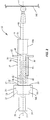
- Figure 1 illustrates a tool 10 for use during double sided incremental forming of a workpiece 100.
- the tool 10 includes a sleeve 30 with a hollow interior space.
- a contact member 40 is positioned within the hollow interior space of the sleeve 30.
- the contact member 40 is sized with a working tip 41 positioned outward beyond the sleeve 30 to contact against a workpiece 100.
- a mount 20 is positioned on the opposing end of the sleeve 30 and configured to connect to a tool holder 90.
- One or more bearing members 50 are mounted in the tool 10.
- the tool 10 is configured to provide for translational movement of the contact member 40 relative to the sleeve 30 along a longitudinal axis A of the tool 10.
- the contact member 40 is also rotatable about the longitudinal axis A relative to the mount 20 (and the attached tool holder 90).
- the axial and rotational movement of the contact member 40 provides for the working tip 41 to remain in contact with the workpiece 100 during the forming process.
- This configuration accommodates axial and transverse tendencies of the tool 10 to misalign and lose contact with the workpiece 100 during the forming process.
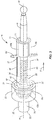
- Figures 2 and 3 illustrate schematic section views of the tool 10.
- the tool 10 includes a mount 20, sleeve 30, contact member 40, one or more bearing members 50a, 50b, 50c, and a spring 60.
- these components are co-axially aligned along a longitudinal axis A of the tool 10.
- one or more of these components is offset from the longitudinal axis A.
- the mount 20 is configured to engage with the tool holder 90.
- the mount 20 includes a first end 21 that faces towards the sleeve 30 and an opposing second end 22.
- the first end 21 includes a base 23 and the second end 22 includes a shaft 24.
- the base 23 supports the sleeve 30 and the shaft 22 includes a smaller width than the base 23 measured across the longitudinal axis A. This larger size provides for contacting and supporting the sleeve 30 and/or positioning one or more bearing members 50.
- a cavity 25 extends into the base 23 from the first end 21.
- the cavity 25 includes a first section 26 at the first end 21, and an axial inward second section 27.
- the first end 21 is flat and forms a contact surface for the sleeve 30.
- the first end 21 includes a protrusion that extends axially outward and away from the shaft 24. The protrusion is sized to fit within an interior of the support the base 23.
- the sleeve 30 extends outward from the first end 21 of the mount 20.
- the sleeve 30 includes an elongated length measured between a first end 31 and opposing second end 32.
- An interior space 33 is formed within the sleeve 30.
- the first end 31 is open and in communication with the hollow interior space 33.
- the interior space 33 extends the entire length of the sleeve 30 (i.e., the sleeve 30 is a cylinder).
- the second end 32 is closed and includes a bottom 35 to provide a support surface for the spring 60.
- the bottom 35 can be formed in various different manners.
- the bottom 35 is formed by a plug that is inserted into the interior space 33 at the second end 32.
- the hollow interior space 33 extends a limited distance inward from the first end 31 of the sleeve 30.
- Slots 36 extend through the hollow interior space 33 from opposing lateral sides of the sleeve 30.
- the slots 36 are positioned axially inward from the ends 31, 32 of the sleeve 30.
- the slots 36 can have various lengths measured between opposing ends 37, 38.
- the sleeve 30 can include a rounded exterior sectional shape.
- one or more axial sections are flat.
- the axial sections of the exterior surface are flat along the slots 36.
- the contact member 40 is movably positioned within the sleeve 30.
- the contact member 40 includes an elongated shape with a working tip 41 and an opposing end 42.
- the length of the contact member 40 is greater than the length of the sleeve 30. This size difference provides for the working tip 41 to extend outward beyond the sleeve 30 with the opposing end 42 positioned within the interior space 33 of the sleeve 30.
- the contact member 40 is offset within the sleeve 30 to position the working tip 41 outward beyond the first end 31 of the sleeve 30.
- the working tip 41 contacts against the workpiece 100 during the forming process.
- the working tip 41 includes a spherical shape.
- the working tip 41 includes a tapered shape.
- the working tip 41 can include various shapes, sizes and configurations, including but not limited to rounded, pointed, and flat.
- the working tip 41 can have various surface finishes, including but not limited to smooth and textured.
- the contact member 40 has a unitary one-piece construction.
- the contact member 40 is constructed from two or more sections that are connected together. As illustrated in Figure 2 , the contact member 40 includes a front section 44 and a rear section 45.
- the front section 44 includes the working tip 41 and the rear section 45 includes the opposing end 42.
- the front and rear sections 44, 45 can be connected together in various manners, including but not limited to a threaded connection, mechanical fasteners, and adhesives.
- the rear section 45 is threaded into a cavity in the front section 44.
- a spring 60 biases the contact member 40 along the longitudinal axis A in a direction of arrow F in Figure 3 .
- the spring 60 is positioned at the bottom 35 of the interior space 33 and is configured to engage with a contact member 40.
- spring 60 is a coil spring that includes a helical shape with coils that are sized to wrap around the lower portion of the contact member 40 at the opposing end 42.
- the lower portion of the contact member 40 can include threads to facilitate the engagement.
- the spring 60 contacts just against the opposing end 42 and is positioned away from the remainder of the contact member 40.
- an opening 46 extends through the width of the contact member 40.
- a pin 65 extends through the opening 46.
- the pin 65 is larger than the width of the contact member 40 and extends outward from the opposing lateral sides.
- the pin 65 also extends through the slots 36 in the sleeve 30. The pin 65 maintains the contact member 40 within the sleeve 30 as the contact member 40 is biased outward in the direction of arrow F in Figure 3 .
- the tool 10 includes one or more bearing members 50 that provide for one or more of rotational and translational movement of the contact member 40.
- the one or more bearing members 50 provide for the working tip 41 of the contact member 40 to remain in contact with the workpiece during the forming process.
- a bearing member 50a is connected to the sleeve 30 and positioned in the interior space 33. As illustrated in Figures 2 and 3 , the bearing member 50a can be positioned at the first end 31 of the sleeve 30. The bearing member 50a provides for rotational and translational movement of the contact member 40. As illustrated in Figure 5 , the bearing member 50a includes a cylindrical body 53 with a hollow interior space 51 that extends the length. The bearing member 50a includes an outer diameter sized to fit into the interior space 33 of the sleeve 30. The bearing member 50a includes an inner diameter sized to receive the contact member 40. In one example, the diameter of the interior space 51 is substantially the same as the outer diameter of the contact member 40.
- rollers 52 are mounted along the inner surface of the interior space 51.
- the rollers 52 extend outward beyond the inner edge of the cylindrical body 53.
- the rollers 52 are rotatable relative to the cylindrical body 53 to provide for the contact member 40 to have rotational movement indicated by arrow C and axial movement indicated by arrow D.
- the rollers 52 can include various shapes, including but not limited to a spherical shape and a cylindrical shape.
- bearing members 50 can be positioned in the mount 20. As illustrated in Figures 2 and 3 , bearing members 50b and 50c are positioned in the mount 20 and support the sleeve 30. Bearing member 50c is mounted within the first section 26 of the cavity 25 and bearing member 50b is mounted in the second section 27 of the cavity 25. The bearing members 50b, 50c support the sleeve 30 and allow rotational movement of the sleeve 30 relative to the mount 20. In one example as illustrated in Figures 2 and 3 , bearing member 50c contacts against the second end 32 of the sleeve 30. The bearing member 50b contacts against the bearing member 50c. In one example, one of the bearing members 50b, 50c is a thrust bearing and the other is a ball bearing.
- the thrust bearing permits translational movement between the sleeve 30 (and the contact member 40) and the mount 20.
- the ball bearing provides rotational movement between the sleeve 30 (and contact member 40) and the mount 20.
- bearing member 50b is a thrust bearing and bearing member 50c is a ball bearing.
- a bearing member 50a is mounted in the sleeve 30 and provides for rotational and translational movement of the contact member 40.
- Bearing member 50a can include roller bearings 52 that contact the contact member 40 and provide for the movement.
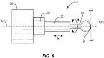
- Figure 6 schematically illustrates a tool 10 that includes a longitudinal axis A.
- the mount 20, sleeve 30, and contact member 40 are coaxially aligned along the longitudinal axis A.
- the mount 20 of the tool 10 is engaged with a tool holder 90.
- the tool holder 90 provides for movement of the tool 10 relative to the workpiece 100 and applies a force for the contact member 40 to deform the workpiece 100.
- the tool 10 is configured for the contact member 40 to remain in contact with the workpiece 100 during the movement of the tool holder 90.
- the tool 10 provides for rotational movement (arrow M) around the longitudinal axis A relative to the tool holder 90.
- the rotational movement is provided by the contact member 40 rotating within the bearing member 50a and/or the sleeve 30 and contact member 40 rotating with one or both of the bearing members 50b, 50c.
- the tool 10 also provides for translational movement (arrow N) of the contact member 40 along the longitudinal axis A.
- the translational movement of the contact member 40 within the sleeve 30 is provided through spring 60 positioned within the interior space 33 of the sleeve 30.
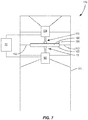
- Figure 7 illustrates a system 110 for using the tool 10 for double sided incremental forming on a workpiece 100.
- the workpiece 100 is rigidly mounted to a frame 111 with one or more clamps 112.
- the clamps 112 prevent movement of the workpiece 100 during the forming process.
- the clamps 112 are further positioned away from the areas of the workpiece 100 that will be contacted during the forming process.
- First and second tool holders 90, 114 are attached to the frame 111.
- the first tool holder 90 is positioned on a first side 101 of the workpiece 100
- the second tool holder 114 is positioned on an opposing second side 102 of the workpiece 100.
- the tool 10 is attached to the first tool holder 90.
- the attachment includes the mount 20 of the tool 10 being engaged within a spindle of the tool holder 90.
- a second tool 115 is attached to the second tool holder 114.
- the second tool holder 114 is the same as the first tool holder 90 and provides for similar rotational and axial movement of the second tool 115.
- the second tool holder 114 includes a different structure than the tool holder 90.
- the first and second tool holders 90, 114 are movable relative to the workpiece 100.
- the first and second tool holders 90, 114 provide movement in multiple degrees of freedom including three translational and one rotational.
- the first and second tool holders 90, 114 can include heating elements that provide for heating the workpiece 100 through the contact with the tools 10, 115.
- One or both of the first and second tool holders 90, 114 can also provide for rotation of the tools 10, 115 respectively.
- a control unit 70 controls the forming process and the operation of the tool holders 90, 114.
- the control unit 70 includes a control circuit 71 and a memory circuit 72.
- the control circuit 71 controls overall operation of the forming process according to program instructions stored in the memory circuit 72.
- the control circuit 71 can include one or more circuits, microcontrollers, microprocessors, hardware, or a combination thereof.
- Memory circuit 72 includes a non-transitory computer readable storage medium storing program instructions, such as a computer program product, that configures the control circuit 71 to implement one or more of the techniques discussed herein.
- Memory circuit 72 can include various memory devices such as, for example, read-only memory, and flash memory.
- Memory circuit 72 can be a separate component as illustrated in Figure 7 , or can be incorporated with the control circuit 71. Alternatively, the control circuit 71 can omit the memory circuit 72, e.g., according to at least some embodiments in which the control circuit 71 is dedicated and non-programmable.
- a user interface 74 provides for a user to control one or more aspects of the forming process.
- the user interface 74 can include one or more input devices 75 such as but not limited to a keypad, touchpad, roller ball, and joystick.
- the one or more input devices 75 provide for a user to enter commands to the control circuit 71.
- the user interface 74 can also include one or more displays 76 for displaying information to the user.
- One or more sensors 73 detect aspects of one or more of the tool holders 90, 114 and/or workpiece 100.
- the system 110 provides for double sided incremental forming of the workpiece 100.
- This process includes the workpiece 100 being formed into a desired geometry by a series of small incremental deformations.
- the forming process includes the working tip 41 of tool 10 and tip 116 of second tool 115 contacting against the opposing sides of the workpiece 100. As illustrated in Figure 9 , the working tip 41 of the contact member 40 of the tool 10 contacts the workpiece 100 on a first side, and the tip 116 of the second tool 115 contacts the workpiece 100 on the opposing side.
- a lubricant can be applied to the surfaces of the workpiece 100 to reduce friction with the tips 41, 116.
- the tool holders 90, 114 are moved about the workpiece 100.
- the tips 41, 116 move in unison and remain aligned or offset depending on the local geometric characteristic of the feature being formed.
- the working tip 41 is maintained in contact with the first side of the workpiece 100.
- friction between the working tip 41 and the workpiece 100 is reduced by the functional aspects of the tool 10.
- the ability of the contact member 40 to rotate and translate about the longitudinal axis A relative to the tool holder 90 accommodates axial and transverse tendency of the working tip 41 to misalign and lose contact with the workpiece 100.
- the tool 10 also reduces and/or prevents loss of contact of the working tip 41 during movement of the tool 10 and tool holder 90.
- the tool 10 also ensures appropriate stiffness levels by incorporation of the spring 60 with the desired stiffness without squeezing of the workpiece 100. This functionality accounts for mismatches and errors resulting from inaccurate estimates (algorithm software machine characteristics) as well as variations relating to machine and work piece compliance, specimen size, tool length, wear and tear, drift in machine performance etc.
- Figure 10 includes a method of using a tool 10 during double sided incremental forming of a workpiece 100.
- the method includes biasing the working tip 41 of the tool 10 against a first side of the workpiece 100 while the tool 10 is mounted in a first tool holder 90 (block 150).
- a second tip 116 of a second tool 115 is positioned against an opposing second side of the workpiece 100 (block 152).
- the second tool 115 is mounted in a second tool holder 114.
- the working tip 41 and the second tip 116 can be aligned or offset depending on the local geometric characteristic feature.
- the first tool holder 90 and the second tool holder 114 move in a synchronized manner relative to the workpiece 100 with the second tip 116 and the working tip 41 remaining aligned/offset depending on the local geometric characteristic of the feature being formed while contacting the opposing sides of the workpiece 100 (block 154).
- the first tool holder 90 and the second tool holder 114 concurrently move relative to workpiece 100 with the second tip 116 and the working tip 41 remaining directly aligned while contacting the opposing sides 101, 102 of the workpiece 100.
- the working tip 41 is translating and rotating relative to a remainder of the tool 10 (block 156).
- the second tip 116 moves in a predefined path without translational motion during forming (because the second tip 116 is functioning as the forming tool).
- This movement of the working tip 41 occurs while moving the working tip 41 in unison with the second tip 116.
- the tool tips 41, 116 swap their roles based on the local geometric characteristic of the feature being formed.
- the tool 10 is used as the forming tool during the forming process and the second tool 115 follows and supports the workpiece 100 during the process.
- the tool 10 is used for support and the tool 115 is used for forming.
- the tools 10, 115 are used for both the forming and support tools.
- the working tip 41 is biased relative to the remainder of the tool 10 and the working tip 41 is maintained in contact against the first side 10 1 of the workpiece 100 with the working tip 41 biased outward away from the first tool holder 90.
- the method includes translating the contact member 40 that includes the working tip 41 along a sleeve 30 that extends around the contact member 40 while moving the working tip 41 along the first side 101 of the workpiece 100. This can further include rotating the contact member 40 relative to the sleeve 30 while moving the working tip 41 along the first side 101 of the workpiece 100.
- the workpiece 100 can be constructed from various materials. Examples include but are not limited to metal, metal alloy, polymeric material, and combinations thereof.
Landscapes
- Engineering & Computer Science (AREA)
- Mechanical Engineering (AREA)
- Jigs For Machine Tools (AREA)
- Mounting, Exchange, And Manufacturing Of Dies (AREA)
- Machine Tool Units (AREA)
Abstract
Description
- The present disclosure relates generally to the field of forming tools and, more specifically, to a forming tool that maintains a working tip of the tool against a workpiece during a forming process.
- Double sided incremental forming is a process for forming relatively thin sheets of material, such as sheet metal. The process includes two tools each having a tip with one of the tools being a support tool and the other tool being a forming tool. The first tool contacts the workpiece on a first side and the second tool contacts the workpiece on an opposing second side. The tools move together such that the tips are aligned or offset on the opposing sides of the sheet. The two tools move their respective tips along a preprogrammed path to form the workpiece and generate the desired part. Roles of the two tools can be interchanged to form features on both sides of the sheet without any additional setup.
- The accuracy of the forming process is improved when both of the tips are aligned (or offset in a controlled manner) and are maintained in contact with the opposing sides of the sheet. However, in conventional tools and methods for double sided incremental forming, the coordinated motion of the two tools can sometimes lead to situations where the contact between the support tool and work piece is lost because of errors originating from assumptions made during simulation, variation in machine stiffness, slight mismatch between predicted and actual sheet thickness at a given point when subjected to deformation, etc. This affects the quality and accuracy of the finished part.
- One approach is to deform the workpiece with the forming and support tool essentially clamping the workpiece and moving together under displacement control. This approach essentially squeezes and stretches the material in- and out- of plane and attempts to achieve the desired shape. However the resulting damage and lack of accuracy makes it an unviable approach. There is a desire to address these issues of conventional tools and methods for double sided incremental forming.
- One aspect is directed to a tool for double sided incremental forming of a workpiece. The tool comprises a sleeve that comprises a first end and a second end and with a hollow interior space that extends into the sleeve from the first end. A mount is positioned at the second end of the sleeve. A spring is positioned within hollow interior space of the sleeve. A contact member comprises a working tip and an opposing end. The opposing end of the contact member is positioned within the interior space of the sleeve and the working tip is positioned outward beyond the sleeve to contact against the workpiece. The contact member is biased outward away from the sleeve by the spring. Bearing members act on the contact member and provide for rotational and translational movement of the contact member relative to the mount.
- In another aspect, the bearing members comprise a translational bearing mounted to the sleeve and having an opening through which the contact member extends, and the translational bearing comprising a plurality of rollers that contact against the contact member and provide for the translational movement of the contact member relative to the sleeve.
- In another aspect, the bearing members comprise a ball bearing operatively connected to the sleeve to provide for rotation of the sleeve relative to the mount.
- In another aspect, each of the mount, the sleeve, the spring, and the contact member are coaxially aligned along a longitudinal axis of the tool.
- In another aspect, the spring is a coil spring with a helical shape that extends around the opposing end of the contact member.
- In another aspect, the working tip of the contact member comprises a spherical shape.
- In another aspect, one of the bearing members is fixedly mounted within the interior space of the sleeve and remains fixed relative to the sleeve during the translational movement of the contact member within the sleeve.
- In another aspect, a pin extends through the contact member and through the sleeve with the pin configured to move with the contact member relative to the sleeve during the translational movement of the contact member and to prevent the contact member from moving out of the interior space of the sleeve.
- One aspect is directed to a tool for double sided incremental forming of a workpiece. The tool comprises a sleeve with a hollow interior space. A mount is connected to the sleeve. A contact member is positioned in the interior space of the sleeve with the contact member comprising a working end configured to contact against the workpiece. A spring is positioned within hollow interior space of the sleeve to bias the contact member in a direction outward from the interior space to maintain the working end of the contact member in contact with the workpiece. A first bearing member is operatively connected to the contact member and provides translational movement of the contact member relative to the mount. A second bearing member is operatively connected to the contact member and provides rotational movement of the contact member relative to the mount.
- In another aspect, the first bearing member is mounted to the sleeve and positioned to contact against the contact member.
- In another aspect, the first bearing member comprises a cylindrical shape that is coaxially aligned with the sleeve and the first bearing member further comprises a plurality of rollers that extend outward from an inner surface of the first bearing member and contact against the contact member.
- In another aspect, both of the first bearing member and the second bearing member are positioned within the mount.
- In another aspect, the mount comprises a shaft configured to be engaged by a tool holder and the mount further comprises a base that extends from the shaft and that supports the second bearing member with the shaft comprising a smaller width than the base.
- In another aspect, slots extend along an axial section of the sleeve, and a pin extends through the contact member and through the slots with the pin sized to slide along the slots during the translational movement of the contact member along the sleeve and to prevent the contact member from moving out of the interior space of the sleeve.
- In another aspect, the sleeve comprises a first end that is open and in communication with the hollow interior space and the sleeve further comprises an opposing second end that is closed and with the spring positioned in the hollow interior space at the closed second end.
- In another aspect, the spring is a coil spring with a helical shape that extends around an opposing end of the contact member that is positioned within the interior space.
- One aspect is directed to a method of using a tool during double sided incremental forming of a workpiece. The method comprises: biasing a working tip of the tool against a first side of the workpiece while the tool is mounted in a first tool holder; positioning a second tip of a second tool against an opposing second side of the workpiece while the second tool is mounted in a second tool holder; concurrently moving the first tool holder and the second tool holder relative to the workpiece with the second tip and the working tip remaining directly aligned while contacting the opposing sides of the workpiece; and translating and rotating the working tip relative to a remainder of the tool while moving the working tip in unison with the second tip.
- In another aspect, the method comprises biasing the working tip relative to the remainder of the tool and maintaining the working tip in contact against the first side of the workpiece with the working tip biased outward away from the first tool holder.
- In another aspect, the method further comprises translating a contact member that comprises the working tip along a sleeve that extends around the contact member while moving the working tip along the first side of the workpiece.
- In another aspect, the method further comprise rotating the contact member relative to the sleeve while moving the working tip along the first side of the workpiece.
- The features, functions and advantages that have been discussed can be achieved independently in various aspects or may be combined in yet other aspects, further details of which can be seen with reference to the following description and the drawings.
-
-
Figure 1 is perspective view of a tool for double sided incremental forming, according to an example embodiment. -
Figure 2 is a schematic side section view of a tool for double sided incremental forming, according to an example embodiment. -
Figure 3 is a schematic perspective section view of a tool for double sided incremental forming, according to an example embodiment. -
Figure 4 is a partial perspective view of a pin that extends through a contact member, according to an example embodiment. -
Figure 5 is a perspective view of a bearing member, according to an example embodiment. -
Figure 6 is a side schematic view of a tool positioned against a workpiece. -
Figure 7 is a side schematic view of a forming system that includes a tool mounted in a tool holder. -
Figure 8 is a schematic diagram of a controller of a forming system. -
Figure 9 is a side schematic view of a working tip of a tool contacting against a first side of a workpiece and a tip of a second tool contacting against an opposing side of the workpiece. -
Figure 10 is a flowchart diagram of a method of using a tool during double sided incremental forming of a workpiece. -
Figure 1 illustrates atool 10 for use during double sided incremental forming of aworkpiece 100. Thetool 10 includes asleeve 30 with a hollow interior space. Acontact member 40 is positioned within the hollow interior space of thesleeve 30. Thecontact member 40 is sized with a workingtip 41 positioned outward beyond thesleeve 30 to contact against aworkpiece 100. Amount 20 is positioned on the opposing end of thesleeve 30 and configured to connect to atool holder 90. One ormore bearing members 50 are mounted in thetool 10. Thetool 10 is configured to provide for translational movement of thecontact member 40 relative to thesleeve 30 along a longitudinal axis A of thetool 10. Thecontact member 40 is also rotatable about the longitudinal axis A relative to the mount 20 (and the attached tool holder 90). The axial and rotational movement of thecontact member 40 provides for the workingtip 41 to remain in contact with theworkpiece 100 during the forming process. This configuration accommodates axial and transverse tendencies of thetool 10 to misalign and lose contact with theworkpiece 100 during the forming process. -
Figures 2 and3 illustrate schematic section views of thetool 10. Thetool 10 includes amount 20,sleeve 30,contact member 40, one ormore bearing members spring 60. In one example, these components are co-axially aligned along a longitudinal axis A of thetool 10. In another example, one or more of these components is offset from the longitudinal axis A. - The
mount 20 is configured to engage with thetool holder 90. Themount 20 includes afirst end 21 that faces towards thesleeve 30 and an opposingsecond end 22. Thefirst end 21 includes abase 23 and thesecond end 22 includes ashaft 24. Thebase 23 supports thesleeve 30 and theshaft 22 includes a smaller width than the base 23 measured across the longitudinal axis A. This larger size provides for contacting and supporting thesleeve 30 and/or positioning one ormore bearing members 50. - In one example as illustrated in
Figures 2 and3 , acavity 25 extends into the base 23 from thefirst end 21. Thecavity 25 includes afirst section 26 at thefirst end 21, and an axial inwardsecond section 27. In another example, thefirst end 21 is flat and forms a contact surface for thesleeve 30. In another example, thefirst end 21 includes a protrusion that extends axially outward and away from theshaft 24. The protrusion is sized to fit within an interior of the support thebase 23. - The
sleeve 30 extends outward from thefirst end 21 of themount 20. Thesleeve 30 includes an elongated length measured between afirst end 31 and opposingsecond end 32. Aninterior space 33 is formed within thesleeve 30. Thefirst end 31 is open and in communication with the hollowinterior space 33. In one example, theinterior space 33 extends the entire length of the sleeve 30 (i.e., thesleeve 30 is a cylinder). Thesecond end 32 is closed and includes a bottom 35 to provide a support surface for thespring 60. The bottom 35 can be formed in various different manners. In one example, the bottom 35 is formed by a plug that is inserted into theinterior space 33 at thesecond end 32. In another example, the hollowinterior space 33 extends a limited distance inward from thefirst end 31 of thesleeve 30. -
Slots 36 extend through the hollowinterior space 33 from opposing lateral sides of thesleeve 30. Theslots 36 are positioned axially inward from theends sleeve 30. Theslots 36 can have various lengths measured between opposing ends 37, 38. - The
sleeve 30 can include a rounded exterior sectional shape. In another example, one or more axial sections are flat. In one specific example as best illustrated inFigure 3 , the axial sections of the exterior surface are flat along theslots 36. - The
contact member 40 is movably positioned within thesleeve 30. Thecontact member 40 includes an elongated shape with a workingtip 41 and an opposingend 42. In one example, the length of thecontact member 40 is greater than the length of thesleeve 30. This size difference provides for the workingtip 41 to extend outward beyond thesleeve 30 with the opposingend 42 positioned within theinterior space 33 of thesleeve 30. Thecontact member 40 is offset within thesleeve 30 to position the workingtip 41 outward beyond thefirst end 31 of thesleeve 30. - The working
tip 41 contacts against theworkpiece 100 during the forming process. In one example as illustrated inFigure 2 , the workingtip 41 includes a spherical shape. In another example, the workingtip 41 includes a tapered shape. The workingtip 41 can include various shapes, sizes and configurations, including but not limited to rounded, pointed, and flat. The workingtip 41 can have various surface finishes, including but not limited to smooth and textured. - In one example, the
contact member 40 has a unitary one-piece construction. In another example, thecontact member 40 is constructed from two or more sections that are connected together. As illustrated inFigure 2 , thecontact member 40 includes afront section 44 and arear section 45. Thefront section 44 includes the workingtip 41 and therear section 45 includes the opposingend 42. The front andrear sections rear section 45 is threaded into a cavity in thefront section 44. - A
spring 60 biases thecontact member 40 along the longitudinal axis A in a direction of arrow F inFigure 3 . Thespring 60 is positioned at the bottom 35 of theinterior space 33 and is configured to engage with acontact member 40. In one example,spring 60 is a coil spring that includes a helical shape with coils that are sized to wrap around the lower portion of thecontact member 40 at the opposingend 42. The lower portion of thecontact member 40 can include threads to facilitate the engagement. In another example, thespring 60 contacts just against the opposingend 42 and is positioned away from the remainder of thecontact member 40. - As illustrated in
Figure 4 , anopening 46 extends through the width of thecontact member 40. Apin 65 extends through theopening 46. Thepin 65 is larger than the width of thecontact member 40 and extends outward from the opposing lateral sides. As illustrated inFigures 2 and3 , thepin 65 also extends through theslots 36 in thesleeve 30. Thepin 65 maintains thecontact member 40 within thesleeve 30 as thecontact member 40 is biased outward in the direction of arrow F inFigure 3 . - The
tool 10 includes one ormore bearing members 50 that provide for one or more of rotational and translational movement of thecontact member 40. The one ormore bearing members 50 provide for the workingtip 41 of thecontact member 40 to remain in contact with the workpiece during the forming process. - In one example, a bearing
member 50a is connected to thesleeve 30 and positioned in theinterior space 33. As illustrated inFigures 2 and3 , the bearingmember 50a can be positioned at thefirst end 31 of thesleeve 30. The bearingmember 50a provides for rotational and translational movement of thecontact member 40. As illustrated inFigure 5 , the bearingmember 50a includes acylindrical body 53 with a hollowinterior space 51 that extends the length. The bearingmember 50a includes an outer diameter sized to fit into theinterior space 33 of thesleeve 30. The bearingmember 50a includes an inner diameter sized to receive thecontact member 40. In one example, the diameter of theinterior space 51 is substantially the same as the outer diameter of thecontact member 40. This similar size supports thecontact member 40 and limits the amount of lateral movement of thecontact member 40.Rollers 52 are mounted along the inner surface of theinterior space 51. Therollers 52 extend outward beyond the inner edge of thecylindrical body 53. Therollers 52 are rotatable relative to thecylindrical body 53 to provide for thecontact member 40 to have rotational movement indicated by arrow C and axial movement indicated by arrow D. Therollers 52 can include various shapes, including but not limited to a spherical shape and a cylindrical shape. - One or
more bearing members 50 can be positioned in themount 20. As illustrated inFigures 2 and3 , bearingmembers mount 20 and support thesleeve 30.Bearing member 50c is mounted within thefirst section 26 of thecavity 25 and bearingmember 50b is mounted in thesecond section 27 of thecavity 25. The bearingmembers sleeve 30 and allow rotational movement of thesleeve 30 relative to themount 20. In one example as illustrated inFigures 2 and3 , bearingmember 50c contacts against thesecond end 32 of thesleeve 30. The bearingmember 50b contacts against the bearingmember 50c. In one example, one of the bearingmembers mount 20. The ball bearing provides rotational movement between the sleeve 30 (and contact member 40) and themount 20. In one specific example, bearingmember 50b is a thrust bearing and bearingmember 50c is a ball bearing. In one example, a bearingmember 50a is mounted in thesleeve 30 and provides for rotational and translational movement of thecontact member 40.Bearing member 50a can includeroller bearings 52 that contact thecontact member 40 and provide for the movement. -
Figure 6 schematically illustrates atool 10 that includes a longitudinal axis A. Themount 20,sleeve 30, andcontact member 40 are coaxially aligned along the longitudinal axis A. Themount 20 of thetool 10 is engaged with atool holder 90. Thetool holder 90 provides for movement of thetool 10 relative to theworkpiece 100 and applies a force for thecontact member 40 to deform theworkpiece 100. Thetool 10 is configured for thecontact member 40 to remain in contact with theworkpiece 100 during the movement of thetool holder 90. As thecontact member 40 slides along theworkpiece 100, thetool 10 provides for rotational movement (arrow M) around the longitudinal axis A relative to thetool holder 90. The rotational movement is provided by thecontact member 40 rotating within the bearingmember 50a and/or thesleeve 30 andcontact member 40 rotating with one or both of the bearingmembers tool 10 also provides for translational movement (arrow N) of thecontact member 40 along the longitudinal axis A. The translational movement of thecontact member 40 within thesleeve 30 is provided throughspring 60 positioned within theinterior space 33 of thesleeve 30. -
Figure 7 illustrates asystem 110 for using thetool 10 for double sided incremental forming on aworkpiece 100. Theworkpiece 100 is rigidly mounted to aframe 111 with one ormore clamps 112. Theclamps 112 prevent movement of theworkpiece 100 during the forming process. Theclamps 112 are further positioned away from the areas of theworkpiece 100 that will be contacted during the forming process. - First and
second tool holders frame 111. Thefirst tool holder 90 is positioned on afirst side 101 of theworkpiece 100, and thesecond tool holder 114 is positioned on an opposingsecond side 102 of theworkpiece 100. Thetool 10 is attached to thefirst tool holder 90. In one example, the attachment includes themount 20 of thetool 10 being engaged within a spindle of thetool holder 90. Asecond tool 115 is attached to thesecond tool holder 114. In one example, thesecond tool holder 114 is the same as thefirst tool holder 90 and provides for similar rotational and axial movement of thesecond tool 115. In another example, thesecond tool holder 114 includes a different structure than thetool holder 90. - The first and
second tool holders workpiece 100. In one example, the first andsecond tool holders second tool holders workpiece 100 through the contact with thetools second tool holders tools - A
control unit 70 controls the forming process and the operation of thetool holders Figure 8 , thecontrol unit 70 includes acontrol circuit 71 and amemory circuit 72. Thecontrol circuit 71 controls overall operation of the forming process according to program instructions stored in thememory circuit 72. Thecontrol circuit 71 can include one or more circuits, microcontrollers, microprocessors, hardware, or a combination thereof.Memory circuit 72 includes a non-transitory computer readable storage medium storing program instructions, such as a computer program product, that configures thecontrol circuit 71 to implement one or more of the techniques discussed herein.Memory circuit 72 can include various memory devices such as, for example, read-only memory, and flash memory.Memory circuit 72 can be a separate component as illustrated inFigure 7 , or can be incorporated with thecontrol circuit 71. Alternatively, thecontrol circuit 71 can omit thememory circuit 72, e.g., according to at least some embodiments in which thecontrol circuit 71 is dedicated and non-programmable. - A
user interface 74 provides for a user to control one or more aspects of the forming process. Theuser interface 74 can include one ormore input devices 75 such as but not limited to a keypad, touchpad, roller ball, and joystick. The one ormore input devices 75 provide for a user to enter commands to thecontrol circuit 71. Theuser interface 74 can also include one ormore displays 76 for displaying information to the user. One ormore sensors 73 detect aspects of one or more of thetool holders workpiece 100. - The
system 110 provides for double sided incremental forming of theworkpiece 100. This process includes theworkpiece 100 being formed into a desired geometry by a series of small incremental deformations. The forming process includes the workingtip 41 oftool 10 andtip 116 ofsecond tool 115 contacting against the opposing sides of theworkpiece 100. As illustrated inFigure 9 , the workingtip 41 of thecontact member 40 of thetool 10 contacts theworkpiece 100 on a first side, and thetip 116 of thesecond tool 115 contacts theworkpiece 100 on the opposing side. - Prior to forming, a lubricant can be applied to the surfaces of the
workpiece 100 to reduce friction with thetips tips tool holders workpiece 100. During forming, thetips - During the forming process, the working
tip 41 is maintained in contact with the first side of theworkpiece 100. During the movement, friction between the workingtip 41 and theworkpiece 100 is reduced by the functional aspects of thetool 10. The ability of thecontact member 40 to rotate and translate about the longitudinal axis A relative to thetool holder 90 accommodates axial and transverse tendency of the workingtip 41 to misalign and lose contact with theworkpiece 100. Thetool 10 also reduces and/or prevents loss of contact of the workingtip 41 during movement of thetool 10 andtool holder 90. Thetool 10 also ensures appropriate stiffness levels by incorporation of thespring 60 with the desired stiffness without squeezing of theworkpiece 100. This functionality accounts for mismatches and errors resulting from inaccurate estimates (algorithm software machine characteristics) as well as variations relating to machine and work piece compliance, specimen size, tool length, wear and tear, drift in machine performance etc. -
Figure 10 includes a method of using atool 10 during double sided incremental forming of aworkpiece 100. The method includes biasing the workingtip 41 of thetool 10 against a first side of theworkpiece 100 while thetool 10 is mounted in a first tool holder 90 (block 150). Asecond tip 116 of asecond tool 115 is positioned against an opposing second side of the workpiece 100 (block 152). Thesecond tool 115 is mounted in asecond tool holder 114. At any instant, the workingtip 41 and thesecond tip 116 can be aligned or offset depending on the local geometric characteristic feature. Thefirst tool holder 90 and thesecond tool holder 114 move in a synchronized manner relative to theworkpiece 100 with thesecond tip 116 and the workingtip 41 remaining aligned/offset depending on the local geometric characteristic of the feature being formed while contacting the opposing sides of the workpiece 100 (block 154). In one example, thefirst tool holder 90 and thesecond tool holder 114 concurrently move relative toworkpiece 100 with thesecond tip 116 and the workingtip 41 remaining directly aligned while contacting the opposingsides workpiece 100. During the movement of thetool 10, the workingtip 41 is translating and rotating relative to a remainder of the tool 10 (block 156). During this movement, thesecond tip 116 moves in a predefined path without translational motion during forming (because thesecond tip 116 is functioning as the forming tool). This movement of the workingtip 41 occurs while moving the workingtip 41 in unison with thesecond tip 116. Thetool tips - In one example, the
tool 10 is used as the forming tool during the forming process and thesecond tool 115 follows and supports theworkpiece 100 during the process. In another example, thetool 10 is used for support and thetool 115 is used for forming. In another example, thetools - In one example during the forming ,the working
tip 41 is biased relative to the remainder of thetool 10 and the workingtip 41 is maintained in contact against thefirst side 10 1 of theworkpiece 100 with the workingtip 41 biased outward away from thefirst tool holder 90. - In one example, the method includes translating the
contact member 40 that includes the workingtip 41 along asleeve 30 that extends around thecontact member 40 while moving the workingtip 41 along thefirst side 101 of theworkpiece 100. This can further include rotating thecontact member 40 relative to thesleeve 30 while moving the workingtip 41 along thefirst side 101 of theworkpiece 100. - The
workpiece 100 can be constructed from various materials. Examples include but are not limited to metal, metal alloy, polymeric material, and combinations thereof. - By the term "substantially" with reference to amounts or measurement values, it is meant that the recited characteristic, parameter, or value need not be achieved exactly. Rather, deviations or variations, including, for example, tolerances, measurement error, measurement accuracy limitations, and other factors known to those skilled in the art, may occur in amounts that do not preclude the effect that the characteristic was intended to provide.
Further, the disclosure comprises embodiments according to the following clauses: - Clause 1. A tool (10) for double sided incremental forming of a workpiece (100), the tool (10) comprising:
- a sleeve (30) comprising a first end (31) and a second end (32) and with a hollow interior space (33) that extends into the sleeve (30) from the first end (31);
- a mount (20) positioned at the second end (32) of the sleeve (30);
- a spring (60) positioned within hollow interior space (33) of the sleeve (30);
- a contact member (40) with a working tip (41) and an opposing end (42), the opposing end (42) of the contact member (40) positioned within the interior space (33) of the sleeve (30) and with the working tip (41) positioned outward beyond the sleeve (30) to contact against the workpiece (100), the contact member (40) biased outward away from the sleeve (30) by the spring (60); and
- bearing members (50) that act on the contact member (40) and provide for rotational and translational movement of the contact member (40) relative to the mount (20).
- Clause 2. The tool of Clause 1, wherein the bearing members (50) comprise a translational bearing (50a) mounted to the sleeve (30) and having an opening (51) through which the contact member (40) extends, the translational bearing (50a) comprising a plurality of rollers (52) that contact against the contact member (40) and provide for the translational movement of the contact member (40) relative to the sleeve (30).
- Clause 3. The tool of Clause 2, wherein the bearing members (50) comprise a ball bearing operatively connected to the sleeve (30) to provide for rotation of the sleeve (30) relative to the mount (20).
- Clause 4. The tool of any of Clauses 1 to 3, wherein each of the mount (20), the sleeve (30), the spring (60), and the contact member (40) are coaxially aligned along a longitudinal axis of the tool (10).
- Clause 5. The tool of any of Clauses 1 to 4, wherein the spring (60) is a coil spring with a helical shape that extends around the opposing end (42) of the contact member (40).
- Clause 6. The tool of any of Clauses 1 to 5, wherein the working tip (41) of the contact member (40) comprises a spherical shape.
- Clause 7. The tool of any of Clauses 1 to 6, wherein one of the bearing members (50) is fixedly mounted within the interior space (33) of the sleeve (30) and remains fixed relative to the sleeve (30) during the translational movement of the contact member (40) within the sleeve (30).
- Clause 8. The tool of any of Clauses 1 to 7, further comprising a pin (65) that extends through the contact member (40) and through the sleeve (30), the pin (65) configured to move with the contact member (40) relative to the sleeve (30) during the translational movement of the contact member (40) and to prevent the contact member (40) from moving out of the interior space (33) of the sleeve (30).
- Clause 9. A tool (10) for double sided incremental forming of a workpiece (100), the tool (10) comprising:
- a sleeve (30) with a hollow interior space (33);
- a mount (20) connected to the sleeve (30);
- a contact member (40) positioned in the interior space (33) of the sleeve (30), the contact member (40) comprising a working end (41) configured to contact against the workpiece (100);
- a spring (60) positioned within hollow interior space (33) of the sleeve (30) to bias the contact member (40) in a direction outward from the interior space (33) to maintain the working end (41) of the contact member (40) in contact with the workpiece (100);
- a first bearing member (50) operatively connected to the contact member (40) that provides translational movement of the contact member (40) relative to the mount (20); and
- a second bearing member (50) operatively connected to the contact member (40) that provides rotational movement of the contact member (40) relative to the mount (20).
-
Clause 10. The tool of Clause 9, wherein the first bearing member (50) is mounted to the sleeve (30) and positioned to contact against the contact member (40). - Clause 11. The tool of
Clause 10, wherein the first bearing member (50) comprises a cylindrical shape that is coaxially aligned with the sleeve (30), the first bearing member (50) further comprises a plurality of rollers (52) that extend outward from an inner surface of the first bearing member (50) and contact against the contact member (40). - Clause 12. The tool of Clause 9, wherein both of the first bearing member (50) and the second bearing member (50) are positioned within the mount (20).
- Clause 13. The tool of any of Clauses 9 to 12, wherein the mount (20) comprises a shaft (24) configured to be engaged by a tool holder (90), the mount (20) further comprises a base (23) that extends from the shaft (24) and that supports the second bearing member (50) with the shaft (24) comprising a smaller width than the base (23).
- Clause 14. The tool of any of Clauses 9 to 13, further comprising:
- slots (36) that extend along an axial section of the sleeve (30); and
- a pin (65) that extends through the contact member (40) and through the slots (36), the pin (65) sized to slide along the slots (36) during the translational movement of the contact member (40) along the sleeve (30) and to prevent the contact member (40) from moving out of the interior space (33) of the sleeve (30).
- Clause 15. The tool of any of Clauses 9 to 14, wherein the sleeve (30) comprises a first end (31) that is open and in communication with the hollow interior space (33), the sleeve (30) further comprises an opposing second end (32) that is closed and with the spring (60) positioned in the hollow interior space (33) at the closed second end (32).
- Clause 16. The tool of any of Clauses 9 to 15, wherein the spring (60) is a coil spring with a helical shape that extends around an opposing end (42) of the contact member (40) that is positioned within the interior space (33).
- Clause 17. A method of using a tool (10) during double sided incremental forming of a workpiece (100), the method comprising:
- biasing a working tip (41) of the tool (10) against a first side of the workpiece (100) while the tool (10) is mounted in a first tool holder (90);
- positioning a second tip (116) of a second tool (115) against an opposing second side of the workpiece (100) while the second tool (115) is mounted in a second tool holder (114);
- concurrently moving the first tool holder (90) and the second tool holder (114) relative to the workpiece (100) with the second tip (116) and the working tip (41) remaining directly aligned while contacting the opposing sides of the workpiece (100); and
- translating and rotating the working tip (41) relative to a remainder of the tool (10) while moving the working tip (41) in unison with the second tip (116).
- Clause 18. The method of Clause 17, further comprising biasing the working tip (41) relative to the remainder of the tool (10) and maintaining the working tip (41) in contact against the first side of the workpiece (100), the working tip (41) biased outward away from the first tool holder (90).
- Clause 19. The method of Clause 17 or Clause 18, further comprising translating a contact member (40) that comprises the working tip (41) along a sleeve (30) that extends around the contact member (40) while moving the working tip (41) along the first side of the workpiece (100).
-
Clause 20. The method of Clause 19, further comprising rotating the contact member (40) relative to the sleeve (30) while moving the working tip (41) along the first side of the workpiece (100). - The present invention may, of course, be carried out in other ways than those specifically set forth herein without departing from essential characteristics of the invention. The present embodiments are to be considered in all respects as illustrative and not restrictive, and all changes coming within the meaning and equivalency range of the appended claims are intended to be embraced therein.
Claims (15)
- A tool (10) for double sided incremental forming of a workpiece (100), the tool (10) comprising:a sleeve (30) comprising a first end (31) and a second end (32) and with a hollow interior space (33) that extends into the sleeve (30) from the first end (31);a mount (20) positioned at the second end (32) of the sleeve (30);a spring (60) positioned within hollow interior space (33) of the sleeve (30);a contact member (40) with a working tip (41) and an opposing end (42), the opposing end (42) of the contact member (40) positioned within the interior space (33) of the sleeve (30) and with the working tip (41) positioned outward beyond the sleeve (30) to contact against the workpiece (100), the contact member (40) biased outward away from the sleeve (30) by the spring (60); andbearing members (50) that act on the contact member (40) and provide for rotational and translational movement of the contact member (40) relative to the mount (20).
- The tool of claim 1, wherein the bearing members (50) comprise a translational bearing (50a) mounted to the sleeve (30) and having an opening (51) through which the contact member (40) extends, the translational bearing (50a) comprising a plurality of rollers (52) that contact against the contact member (40) and provide for the translational movement of the contact member (40) relative to the sleeve (30).
- The tool of claim 2, wherein the bearing members (50) comprise a ball bearing operatively connected to the sleeve (30) to provide for rotation of the sleeve (30) relative to the mount (20).
- The tool of any of claims 1 to 3, wherein each of the mount (20), the sleeve (30), the spring (60), and the contact member (40) are coaxially aligned along a longitudinal axis of the tool (10).
- The tool of any of claims 1 to 4, wherein the spring (60) is a coil spring with a helical shape that extends around the opposing end (42) of the contact member (40).
- The tool of any of claims 1 to 5, wherein the working tip (41) of the contact member (40) comprises a spherical shape.
- The tool of any of claims 1 to 6, wherein one of the bearing members (50) is fixedly mounted within the interior space (33) of the sleeve (30) and remains fixed relative to the sleeve (30) during the translational movement of the contact member (40) within the sleeve (30).
- The tool of any of claims 1 to 7, further comprising a pin (65) that extends through the contact member (40) and through the sleeve (30), the pin (65) configured to move with the contact member (40) relative to the sleeve (30) during the translational movement of the contact member (40) and to prevent the contact member (40) from moving out of the interior space (33) of the sleeve (30).
- A method of using a tool (10) during double sided incremental forming of a workpiece (100), the method comprising:biasing a working tip (41) of the tool (10) against a first side of the workpiece (100) while the tool (10) is mounted in a first tool holder (90);positioning a second tip (116) of a second tool (115) against an opposing second side of the workpiece (100) while the second tool (115) is mounted in a second tool holder (114);concurrently moving the first tool holder (90) and the second tool holder (114) relative to the workpiece (100) with the second tip (116) and the working tip (41) remaining directly aligned while contacting the opposing sides of the workpiece (100); andtranslating and rotating the working tip (41) relative to a remainder of the tool (10) while moving the working tip (41) in unison with the second tip (116).
- The method of claim 9, further comprising biasing the working tip (41) relative to the remainder of the tool (10) and maintaining the working tip (41) in contact against the first side of the workpiece (100), the working tip (41) biased outward away from the first tool holder (90).
- The method of claim 9 or claim 10, wherein the tool (10) comprises a contact member (40), the method further comprising translating the contact member (40) that comprises the working tip (41) along a sleeve (30) that extends around the contact member (40) while moving the working tip (41) along the first side of the workpiece (100).
- The method of claim 11, further comprising rotating the contact member (40) relative to the sleeve (30) while moving the working tip (41) along the first side of the workpiece (100).
- The method of any of claims 9-12, wherein the working tip (41) comprises a spherical shape.
- The method of any of claims 9-13, wherein the second tip (116) moves in a predefined path without translational motion during forming.
- The method of any of claims 9-14, wherein the first tool holder (90) and the second tool holder (114) move in a synchronized manner relative to the workpiece (100) with the second tip (116) and the working tip (41) remaining aligned/offset depending on a local geometric characteristic of the feature being formed while contacting the opposing sides of the workpiece (100).
Applications Claiming Priority (1)
| Application Number | Priority Date | Filing Date | Title |
|---|---|---|---|
| US16/778,005 US11484932B2 (en) | 2020-01-31 | 2020-01-31 | Tool for enhanced accuracy in double-sided incremental forming |
Publications (2)
| Publication Number | Publication Date |
|---|---|
| EP3858511A1 true EP3858511A1 (en) | 2021-08-04 |
| EP3858511B1 EP3858511B1 (en) | 2024-07-03 |
Family
ID=74184530
Family Applications (1)
| Application Number | Title | Priority Date | Filing Date |
|---|---|---|---|
| EP21151695.0A Active EP3858511B1 (en) | 2020-01-31 | 2021-01-14 | Tool for double-sided incremental formingn and method of using the tool |
Country Status (4)
| Country | Link |
|---|---|
| US (1) | US11484932B2 (en) |
| EP (1) | EP3858511B1 (en) |
| JP (1) | JP7621128B2 (en) |
| CN (1) | CN113198919A (en) |
Citations (7)
| Publication number | Priority date | Publication date | Assignee | Title |
|---|---|---|---|---|
| US20050229666A1 (en) * | 2004-03-30 | 2005-10-20 | Tesco Engineering Inc. | Roller type hemming apparatus |
| WO2007138173A1 (en) * | 2006-05-31 | 2007-12-06 | Technomark | Marking device for impact detection and corresponding process |
| EP2505279A1 (en) * | 2011-03-29 | 2012-10-03 | Mta Sztaki | Device for two sided incremental sheet forming |
| CN103639249A (en) * | 2013-12-03 | 2014-03-19 | 上海交通大学 | Sheet double-point incremental forming device and method |
| US20140345351A1 (en) * | 2007-05-09 | 2014-11-27 | The Penn State Research Foundation | Apparatus for electrical-assisted incremental forming and process thereof |
| DE102013110855A1 (en) * | 2013-10-01 | 2015-04-02 | Rheinisch-Westfälische Technische Hochschule (Rwth) Aachen | Forming device for incremental sheet metal forming |
| CN110369853A (en) * | 2019-07-26 | 2019-10-25 | 上海交通大学 | A kind of laminated plate two point synchronized links and progressive compound molding device and method |
Family Cites Families (12)
| Publication number | Priority date | Publication date | Assignee | Title |
|---|---|---|---|---|
| US3126793A (en) * | 1964-03-31 | Rotary tool | ||
| US5277526A (en) * | 1990-08-09 | 1994-01-11 | Jobs S.P.A. | Apparatus with floating tool for drilling, boring, flaring and the like at a set depth using jigs |
| JPH04204801A (en) * | 1990-11-30 | 1992-07-27 | Matsushita Electric Ind Co Ltd | Surface working device |
| JP3470168B2 (en) * | 1999-03-01 | 2003-11-25 | 株式会社日立製作所 | Method and apparatus for successively forming metal sheet and apparatus and molded product |
| US7607871B1 (en) * | 2007-04-05 | 2009-10-27 | Lance Nelson | Spring loaded tool with floating depth control for countersinking holes or engraving |
| CN101306451B (en) * | 2008-06-30 | 2010-06-02 | 南京航空航天大学 | Incremental forming press head and its forming device with adjustable pressure |
| US8322176B2 (en) | 2009-02-11 | 2012-12-04 | Ford Global Technologies, Llc | System and method for incrementally forming a workpiece |
| WO2013062827A1 (en) * | 2011-10-24 | 2013-05-02 | Northwestern University | System and method for accumulative double sided incremental forming |
| JP5851813B2 (en) * | 2011-12-05 | 2016-02-03 | 三菱重工業株式会社 | Curvature holding device, curving method and curving method for plate-like workpiece |
| DE102017123102A1 (en) * | 2016-11-04 | 2018-05-09 | Makita Corporation | power tool |
| CN107597959A (en) * | 2017-08-21 | 2018-01-19 | 上海交通大学 | Two-sided multi-point incremental shapes electric servicing unit |
| ES3010126T3 (en) * | 2018-04-08 | 2025-04-01 | Star Co Ltd | Drawing-out tool for sheet metal |
-
2020
- 2020-01-31 US US16/778,005 patent/US11484932B2/en active Active
-
2021
- 2021-01-14 EP EP21151695.0A patent/EP3858511B1/en active Active
- 2021-01-28 CN CN202110115665.7A patent/CN113198919A/en active Pending
- 2021-01-29 JP JP2021013563A patent/JP7621128B2/en active Active
Patent Citations (7)
| Publication number | Priority date | Publication date | Assignee | Title |
|---|---|---|---|---|
| US20050229666A1 (en) * | 2004-03-30 | 2005-10-20 | Tesco Engineering Inc. | Roller type hemming apparatus |
| WO2007138173A1 (en) * | 2006-05-31 | 2007-12-06 | Technomark | Marking device for impact detection and corresponding process |
| US20140345351A1 (en) * | 2007-05-09 | 2014-11-27 | The Penn State Research Foundation | Apparatus for electrical-assisted incremental forming and process thereof |
| EP2505279A1 (en) * | 2011-03-29 | 2012-10-03 | Mta Sztaki | Device for two sided incremental sheet forming |
| DE102013110855A1 (en) * | 2013-10-01 | 2015-04-02 | Rheinisch-Westfälische Technische Hochschule (Rwth) Aachen | Forming device for incremental sheet metal forming |
| CN103639249A (en) * | 2013-12-03 | 2014-03-19 | 上海交通大学 | Sheet double-point incremental forming device and method |
| CN110369853A (en) * | 2019-07-26 | 2019-10-25 | 上海交通大学 | A kind of laminated plate two point synchronized links and progressive compound molding device and method |
Non-Patent Citations (1)
| Title |
|---|
| XU D K ET AL: "Enhancement of process capabilities in electrically-assisted double sided incremental forming", MATERIALS & DESIGN, vol. 92, 8 December 2015 (2015-12-08), pages 268 - 280, XP029384818, ISSN: 0264-1275, DOI: 10.1016/J.MATDES.2015.12.009 * |
Also Published As
| Publication number | Publication date |
|---|---|
| CN113198919A (en) | 2021-08-03 |
| JP7621128B2 (en) | 2025-01-24 |
| EP3858511B1 (en) | 2024-07-03 |
| JP2021175577A (en) | 2021-11-04 |
| US20210237140A1 (en) | 2021-08-05 |
| US11484932B2 (en) | 2022-11-01 |
Similar Documents
| Publication | Publication Date | Title |
|---|---|---|
| CA2829737C (en) | Friction stir spot welding device and friction stir spot welding method | |
| DE102012209079B3 (en) | Thermal processing of rod-like workpiece by thermal processing beam, comprises: clamping workpiece in clamping devices along feed direction, supporting workpiece by supporting element, and rotating rod-like workpiece | |
| EP2687314B1 (en) | Friction stir spot welding device and friction stir spot welding method | |
| JP5753810B2 (en) | Steady rest | |
| US5237780A (en) | Steady rest with internal centerline adjustment | |
| DE102017118668A1 (en) | machine tool | |
| EP2583786B1 (en) | Steady rest | |
| JP2015180513A (en) | Friction stir spot welding apparatus and friction stir spot welding method | |
| US11484932B2 (en) | Tool for enhanced accuracy in double-sided incremental forming | |
| EP3504016A1 (en) | Thread rolling assembly | |
| CN120901312B (en) | A horizontal CNC lathe | |
| CN101829875B (en) | Cylinder positioning device in thin-wall drilling welding machine | |
| EP2218545B1 (en) | Device and method for fine processing of a rotation-symmetric workpiece surface | |
| US2257609A (en) | Pilot for boring bars | |
| JP4988195B2 (en) | Wire electrode feeding mechanism and wire electric discharge machine | |
| CN219151218U (en) | Mechanical part correcting device | |
| DE102017222132B4 (en) | Sensor for a coordinate measuring machine | |
| JP5570318B2 (en) | Equalizer for welding machine | |
| US4068547A (en) | Tail stock | |
| WO2018190038A1 (en) | Device and method for cutting hole inner surface | |
| JP2012161904A (en) | Composite tool, machining method, and machine tool | |
| JP5333033B2 (en) | Guided reamer and processing method using guided reamer | |
| JP3032672B2 (en) | Taper processing device | |
| CN219581546U (en) | Carriage panel processing bender | |
| JPWO2021054153A5 (en) |
Legal Events
| Date | Code | Title | Description |
|---|---|---|---|
| PUAI | Public reference made under article 153(3) epc to a published international application that has entered the european phase |
Free format text: ORIGINAL CODE: 0009012 |
|
| STAA | Information on the status of an ep patent application or granted ep patent |
Free format text: STATUS: THE APPLICATION HAS BEEN PUBLISHED |
|
| AK | Designated contracting states |
Kind code of ref document: A1 Designated state(s): AL AT BE BG CH CY CZ DE DK EE ES FI FR GB GR HR HU IE IS IT LI LT LU LV MC MK MT NL NO PL PT RO RS SE SI SK SM TR |
|
| STAA | Information on the status of an ep patent application or granted ep patent |
Free format text: STATUS: REQUEST FOR EXAMINATION WAS MADE |
|
| 17P | Request for examination filed |
Effective date: 20220113 |
|
| RBV | Designated contracting states (corrected) |
Designated state(s): AL AT BE BG CH CY CZ DE DK EE ES FI FR GB GR HR HU IE IS IT LI LT LU LV MC MK MT NL NO PL PT RO RS SE SI SK SM TR |
|
| RAP3 | Party data changed (applicant data changed or rights of an application transferred) |
Owner name: THE BOEING COMPANY |
|
| GRAP | Despatch of communication of intention to grant a patent |
Free format text: ORIGINAL CODE: EPIDOSNIGR1 |
|
| STAA | Information on the status of an ep patent application or granted ep patent |
Free format text: STATUS: GRANT OF PATENT IS INTENDED |
|
| INTG | Intention to grant announced |
Effective date: 20240129 |
|
| GRAJ | Information related to disapproval of communication of intention to grant by the applicant or resumption of examination proceedings by the epo deleted |
Free format text: ORIGINAL CODE: EPIDOSDIGR1 |
|
| STAA | Information on the status of an ep patent application or granted ep patent |
Free format text: STATUS: REQUEST FOR EXAMINATION WAS MADE |
|
| GRAP | Despatch of communication of intention to grant a patent |
Free format text: ORIGINAL CODE: EPIDOSNIGR1 |
|
| STAA | Information on the status of an ep patent application or granted ep patent |
Free format text: STATUS: GRANT OF PATENT IS INTENDED |
|
| GRAS | Grant fee paid |
Free format text: ORIGINAL CODE: EPIDOSNIGR3 |
|
| INTG | Intention to grant announced |
Effective date: 20240507 |
|
| GRAA | (expected) grant |
Free format text: ORIGINAL CODE: 0009210 |
|
| STAA | Information on the status of an ep patent application or granted ep patent |
Free format text: STATUS: THE PATENT HAS BEEN GRANTED |
|
| AK | Designated contracting states |
Kind code of ref document: B1 Designated state(s): AL AT BE BG CH CY CZ DE DK EE ES FI FR GB GR HR HU IE IS IT LI LT LU LV MC MK MT NL NO PL PT RO RS SE SI SK SM TR |
|
| P01 | Opt-out of the competence of the unified patent court (upc) registered |
Effective date: 20240528 |
|
| REG | Reference to a national code |
Ref country code: CH Ref legal event code: EP |
|
| REG | Reference to a national code |
Ref country code: DE Ref legal event code: R096 Ref document number: 602021014978 Country of ref document: DE |
|
| REG | Reference to a national code |
Ref country code: LT Ref legal event code: MG9D |
|
| REG | Reference to a national code |
Ref country code: NL Ref legal event code: MP Effective date: 20240703 |
|
| PG25 | Lapsed in a contracting state [announced via postgrant information from national office to epo] |
Ref country code: PT Free format text: LAPSE BECAUSE OF FAILURE TO SUBMIT A TRANSLATION OF THE DESCRIPTION OR TO PAY THE FEE WITHIN THE PRESCRIBED TIME-LIMIT Effective date: 20241104 |
|
| REG | Reference to a national code |
Ref country code: AT Ref legal event code: MK05 Ref document number: 1699302 Country of ref document: AT Kind code of ref document: T Effective date: 20240703 |
|
| PG25 | Lapsed in a contracting state [announced via postgrant information from national office to epo] |
Ref country code: NL Free format text: LAPSE BECAUSE OF FAILURE TO SUBMIT A TRANSLATION OF THE DESCRIPTION OR TO PAY THE FEE WITHIN THE PRESCRIBED TIME-LIMIT Effective date: 20240703 |
|
| PG25 | Lapsed in a contracting state [announced via postgrant information from national office to epo] |
Ref country code: PT Free format text: LAPSE BECAUSE OF FAILURE TO SUBMIT A TRANSLATION OF THE DESCRIPTION OR TO PAY THE FEE WITHIN THE PRESCRIBED TIME-LIMIT Effective date: 20241104 Ref country code: NL Free format text: LAPSE BECAUSE OF FAILURE TO SUBMIT A TRANSLATION OF THE DESCRIPTION OR TO PAY THE FEE WITHIN THE PRESCRIBED TIME-LIMIT Effective date: 20240703 |
|
| PG25 | Lapsed in a contracting state [announced via postgrant information from national office to epo] |
Ref country code: NO Free format text: LAPSE BECAUSE OF FAILURE TO SUBMIT A TRANSLATION OF THE DESCRIPTION OR TO PAY THE FEE WITHIN THE PRESCRIBED TIME-LIMIT Effective date: 20241003 |
|
| PG25 | Lapsed in a contracting state [announced via postgrant information from national office to epo] |
Ref country code: FI Free format text: LAPSE BECAUSE OF FAILURE TO SUBMIT A TRANSLATION OF THE DESCRIPTION OR TO PAY THE FEE WITHIN THE PRESCRIBED TIME-LIMIT Effective date: 20240703 Ref country code: PL Free format text: LAPSE BECAUSE OF FAILURE TO SUBMIT A TRANSLATION OF THE DESCRIPTION OR TO PAY THE FEE WITHIN THE PRESCRIBED TIME-LIMIT Effective date: 20240703 Ref country code: GR Free format text: LAPSE BECAUSE OF FAILURE TO SUBMIT A TRANSLATION OF THE DESCRIPTION OR TO PAY THE FEE WITHIN THE PRESCRIBED TIME-LIMIT Effective date: 20241004 |
|
| PG25 | Lapsed in a contracting state [announced via postgrant information from national office to epo] |
Ref country code: BG Free format text: LAPSE BECAUSE OF FAILURE TO SUBMIT A TRANSLATION OF THE DESCRIPTION OR TO PAY THE FEE WITHIN THE PRESCRIBED TIME-LIMIT Effective date: 20240703 |
|
| PG25 | Lapsed in a contracting state [announced via postgrant information from national office to epo] |
Ref country code: LV Free format text: LAPSE BECAUSE OF FAILURE TO SUBMIT A TRANSLATION OF THE DESCRIPTION OR TO PAY THE FEE WITHIN THE PRESCRIBED TIME-LIMIT Effective date: 20240703 |
|
| PG25 | Lapsed in a contracting state [announced via postgrant information from national office to epo] |
Ref country code: IS Free format text: LAPSE BECAUSE OF FAILURE TO SUBMIT A TRANSLATION OF THE DESCRIPTION OR TO PAY THE FEE WITHIN THE PRESCRIBED TIME-LIMIT Effective date: 20241103 Ref country code: AT Free format text: LAPSE BECAUSE OF FAILURE TO SUBMIT A TRANSLATION OF THE DESCRIPTION OR TO PAY THE FEE WITHIN THE PRESCRIBED TIME-LIMIT Effective date: 20240703 |
|
| PG25 | Lapsed in a contracting state [announced via postgrant information from national office to epo] |
Ref country code: HR Free format text: LAPSE BECAUSE OF FAILURE TO SUBMIT A TRANSLATION OF THE DESCRIPTION OR TO PAY THE FEE WITHIN THE PRESCRIBED TIME-LIMIT Effective date: 20240703 Ref country code: CZ Free format text: LAPSE BECAUSE OF FAILURE TO SUBMIT A TRANSLATION OF THE DESCRIPTION OR TO PAY THE FEE WITHIN THE PRESCRIBED TIME-LIMIT Effective date: 20240703 |
|
| PG25 | Lapsed in a contracting state [announced via postgrant information from national office to epo] |
Ref country code: ES Free format text: LAPSE BECAUSE OF FAILURE TO SUBMIT A TRANSLATION OF THE DESCRIPTION OR TO PAY THE FEE WITHIN THE PRESCRIBED TIME-LIMIT Effective date: 20240703 Ref country code: RS Free format text: LAPSE BECAUSE OF FAILURE TO SUBMIT A TRANSLATION OF THE DESCRIPTION OR TO PAY THE FEE WITHIN THE PRESCRIBED TIME-LIMIT Effective date: 20241003 |
|
| PG25 | Lapsed in a contracting state [announced via postgrant information from national office to epo] |
Ref country code: RS Free format text: LAPSE BECAUSE OF FAILURE TO SUBMIT A TRANSLATION OF THE DESCRIPTION OR TO PAY THE FEE WITHIN THE PRESCRIBED TIME-LIMIT Effective date: 20241003 Ref country code: PL Free format text: LAPSE BECAUSE OF FAILURE TO SUBMIT A TRANSLATION OF THE DESCRIPTION OR TO PAY THE FEE WITHIN THE PRESCRIBED TIME-LIMIT Effective date: 20240703 Ref country code: NO Free format text: LAPSE BECAUSE OF FAILURE TO SUBMIT A TRANSLATION OF THE DESCRIPTION OR TO PAY THE FEE WITHIN THE PRESCRIBED TIME-LIMIT Effective date: 20241003 Ref country code: LV Free format text: LAPSE BECAUSE OF FAILURE TO SUBMIT A TRANSLATION OF THE DESCRIPTION OR TO PAY THE FEE WITHIN THE PRESCRIBED TIME-LIMIT Effective date: 20240703 Ref country code: IS Free format text: LAPSE BECAUSE OF FAILURE TO SUBMIT A TRANSLATION OF THE DESCRIPTION OR TO PAY THE FEE WITHIN THE PRESCRIBED TIME-LIMIT Effective date: 20241103 Ref country code: HR Free format text: LAPSE BECAUSE OF FAILURE TO SUBMIT A TRANSLATION OF THE DESCRIPTION OR TO PAY THE FEE WITHIN THE PRESCRIBED TIME-LIMIT Effective date: 20240703 Ref country code: GR Free format text: LAPSE BECAUSE OF FAILURE TO SUBMIT A TRANSLATION OF THE DESCRIPTION OR TO PAY THE FEE WITHIN THE PRESCRIBED TIME-LIMIT Effective date: 20241004 Ref country code: FI Free format text: LAPSE BECAUSE OF FAILURE TO SUBMIT A TRANSLATION OF THE DESCRIPTION OR TO PAY THE FEE WITHIN THE PRESCRIBED TIME-LIMIT Effective date: 20240703 Ref country code: ES Free format text: LAPSE BECAUSE OF FAILURE TO SUBMIT A TRANSLATION OF THE DESCRIPTION OR TO PAY THE FEE WITHIN THE PRESCRIBED TIME-LIMIT Effective date: 20240703 Ref country code: CZ Free format text: LAPSE BECAUSE OF FAILURE TO SUBMIT A TRANSLATION OF THE DESCRIPTION OR TO PAY THE FEE WITHIN THE PRESCRIBED TIME-LIMIT Effective date: 20240703 Ref country code: BG Free format text: LAPSE BECAUSE OF FAILURE TO SUBMIT A TRANSLATION OF THE DESCRIPTION OR TO PAY THE FEE WITHIN THE PRESCRIBED TIME-LIMIT Effective date: 20240703 Ref country code: AT Free format text: LAPSE BECAUSE OF FAILURE TO SUBMIT A TRANSLATION OF THE DESCRIPTION OR TO PAY THE FEE WITHIN THE PRESCRIBED TIME-LIMIT Effective date: 20240703 |
|
| REG | Reference to a national code |
Ref country code: DE Ref legal event code: R097 Ref document number: 602021014978 Country of ref document: DE |
|
| PG25 | Lapsed in a contracting state [announced via postgrant information from national office to epo] |
Ref country code: DK Free format text: LAPSE BECAUSE OF FAILURE TO SUBMIT A TRANSLATION OF THE DESCRIPTION OR TO PAY THE FEE WITHIN THE PRESCRIBED TIME-LIMIT Effective date: 20240703 Ref country code: RO Free format text: LAPSE BECAUSE OF FAILURE TO SUBMIT A TRANSLATION OF THE DESCRIPTION OR TO PAY THE FEE WITHIN THE PRESCRIBED TIME-LIMIT Effective date: 20240703 Ref country code: SM Free format text: LAPSE BECAUSE OF FAILURE TO SUBMIT A TRANSLATION OF THE DESCRIPTION OR TO PAY THE FEE WITHIN THE PRESCRIBED TIME-LIMIT Effective date: 20240703 |
|
| PG25 | Lapsed in a contracting state [announced via postgrant information from national office to epo] |
Ref country code: EE Free format text: LAPSE BECAUSE OF FAILURE TO SUBMIT A TRANSLATION OF THE DESCRIPTION OR TO PAY THE FEE WITHIN THE PRESCRIBED TIME-LIMIT Effective date: 20240703 |
|
| PG25 | Lapsed in a contracting state [announced via postgrant information from national office to epo] |
Ref country code: IT Free format text: LAPSE BECAUSE OF FAILURE TO SUBMIT A TRANSLATION OF THE DESCRIPTION OR TO PAY THE FEE WITHIN THE PRESCRIBED TIME-LIMIT Effective date: 20240703 Ref country code: SK Free format text: LAPSE BECAUSE OF FAILURE TO SUBMIT A TRANSLATION OF THE DESCRIPTION OR TO PAY THE FEE WITHIN THE PRESCRIBED TIME-LIMIT Effective date: 20240703 |
|
| PLBE | No opposition filed within time limit |
Free format text: ORIGINAL CODE: 0009261 |
|
| STAA | Information on the status of an ep patent application or granted ep patent |
Free format text: STATUS: NO OPPOSITION FILED WITHIN TIME LIMIT |
|
| 26N | No opposition filed |
Effective date: 20250404 |
|
| REG | Reference to a national code |
Ref country code: CH Ref legal event code: PL |
|
| PG25 | Lapsed in a contracting state [announced via postgrant information from national office to epo] |
Ref country code: SE Free format text: LAPSE BECAUSE OF FAILURE TO SUBMIT A TRANSLATION OF THE DESCRIPTION OR TO PAY THE FEE WITHIN THE PRESCRIBED TIME-LIMIT Effective date: 20240703 |
|
| PG25 | Lapsed in a contracting state [announced via postgrant information from national office to epo] |
Ref country code: MC Free format text: LAPSE BECAUSE OF FAILURE TO SUBMIT A TRANSLATION OF THE DESCRIPTION OR TO PAY THE FEE WITHIN THE PRESCRIBED TIME-LIMIT Effective date: 20240703 Ref country code: LU Free format text: LAPSE BECAUSE OF NON-PAYMENT OF DUE FEES Effective date: 20250114 |
|
| PG25 | Lapsed in a contracting state [announced via postgrant information from national office to epo] |
Ref country code: BE Free format text: LAPSE BECAUSE OF NON-PAYMENT OF DUE FEES Effective date: 20250131 |
|
| PG25 | Lapsed in a contracting state [announced via postgrant information from national office to epo] |
Ref country code: CH Free format text: LAPSE BECAUSE OF NON-PAYMENT OF DUE FEES Effective date: 20250131 |
|
| REG | Reference to a national code |
Ref country code: BE Ref legal event code: MM Effective date: 20250131 |
|
| PG25 | Lapsed in a contracting state [announced via postgrant information from national office to epo] |
Ref country code: IE Free format text: LAPSE BECAUSE OF NON-PAYMENT OF DUE FEES Effective date: 20250114 |
|
| PGFP | Annual fee paid to national office [announced via postgrant information from national office to epo] |
Ref country code: GB Payment date: 20260127 Year of fee payment: 6 |
|
| PGFP | Annual fee paid to national office [announced via postgrant information from national office to epo] |
Ref country code: DE Payment date: 20260128 Year of fee payment: 6 |
|
| PGFP | Annual fee paid to national office [announced via postgrant information from national office to epo] |
Ref country code: FR Payment date: 20260126 Year of fee payment: 6 |