EP3858455B1 - Filter assembly for gas turbine engine - Google Patents
Filter assembly for gas turbine engine Download PDFInfo
- Publication number
- EP3858455B1 EP3858455B1 EP21154429.1A EP21154429A EP3858455B1 EP 3858455 B1 EP3858455 B1 EP 3858455B1 EP 21154429 A EP21154429 A EP 21154429A EP 3858455 B1 EP3858455 B1 EP 3858455B1
- Authority
- EP
- European Patent Office
- Prior art keywords
- cover
- filter
- cartridge
- housing
- assembly
- Prior art date
- Legal status (The legal status is an assumption and is not a legal conclusion. Google has not performed a legal analysis and makes no representation as to the accuracy of the status listed.)
- Active
Links
Images





Classifications
-
- B—PERFORMING OPERATIONS; TRANSPORTING
- B01—PHYSICAL OR CHEMICAL PROCESSES OR APPARATUS IN GENERAL
- B01D—SEPARATION
- B01D46/00—Filters or filtering processes specially modified for separating dispersed particles from gases or vapours
- B01D46/0002—Casings; Housings; Frame constructions
- B01D46/0005—Mounting of filtering elements within casings, housings or frames
-
- B—PERFORMING OPERATIONS; TRANSPORTING
- B01—PHYSICAL OR CHEMICAL PROCESSES OR APPARATUS IN GENERAL
- B01D—SEPARATION
- B01D29/00—Filters with filtering elements stationary during filtration, e.g. pressure or suction filters, not covered by groups B01D24/00 - B01D27/00; Filtering elements therefor
- B01D29/11—Filters with filtering elements stationary during filtration, e.g. pressure or suction filters, not covered by groups B01D24/00 - B01D27/00; Filtering elements therefor with bag, cage, hose, tube, sleeve or like filtering elements
- B01D29/13—Supported filter elements
- B01D29/15—Supported filter elements arranged for inward flow filtration
- B01D29/21—Supported filter elements arranged for inward flow filtration with corrugated, folded or wound sheets
-
- B—PERFORMING OPERATIONS; TRANSPORTING
- B01—PHYSICAL OR CHEMICAL PROCESSES OR APPARATUS IN GENERAL
- B01D—SEPARATION
- B01D29/00—Filters with filtering elements stationary during filtration, e.g. pressure or suction filters, not covered by groups B01D24/00 - B01D27/00; Filtering elements therefor
- B01D29/96—Filters with filtering elements stationary during filtration, e.g. pressure or suction filters, not covered by groups B01D24/00 - B01D27/00; Filtering elements therefor in which the filtering elements are moved between filtering operations; Particular measures for removing or replacing the filtering elements; Transport systems for filters
-
- B—PERFORMING OPERATIONS; TRANSPORTING
- B01—PHYSICAL OR CHEMICAL PROCESSES OR APPARATUS IN GENERAL
- B01D—SEPARATION
- B01D35/00—Filtering devices having features not specifically covered by groups B01D24/00 - B01D33/00, or for applications not specifically covered by groups B01D24/00 - B01D33/00; Auxiliary devices for filtration; Filter housing constructions
- B01D35/30—Filter housing constructions
-
- B—PERFORMING OPERATIONS; TRANSPORTING
- B01—PHYSICAL OR CHEMICAL PROCESSES OR APPARATUS IN GENERAL
- B01D—SEPARATION
- B01D46/00—Filters or filtering processes specially modified for separating dispersed particles from gases or vapours
- B01D46/24—Particle separators, e.g. dust precipitators, using rigid hollow filter bodies
- B01D46/2403—Particle separators, e.g. dust precipitators, using rigid hollow filter bodies characterised by the physical shape or structure of the filtering element
- B01D46/2411—Filter cartridges
-
- B—PERFORMING OPERATIONS; TRANSPORTING
- B01—PHYSICAL OR CHEMICAL PROCESSES OR APPARATUS IN GENERAL
- B01D—SEPARATION
- B01D2201/00—Details relating to filtering apparatus
- B01D2201/29—Filter cartridge constructions
- B01D2201/291—End caps
-
- B—PERFORMING OPERATIONS; TRANSPORTING
- B01—PHYSICAL OR CHEMICAL PROCESSES OR APPARATUS IN GENERAL
- B01D—SEPARATION
- B01D2201/00—Details relating to filtering apparatus
- B01D2201/30—Filter housing constructions
- B01D2201/301—Details of removable closures, lids, caps, filter heads
-
- B—PERFORMING OPERATIONS; TRANSPORTING
- B01—PHYSICAL OR CHEMICAL PROCESSES OR APPARATUS IN GENERAL
- B01D—SEPARATION
- B01D2201/00—Details relating to filtering apparatus
- B01D2201/30—Filter housing constructions
- B01D2201/301—Details of removable closures, lids, caps, filter heads
- B01D2201/302—Details of removable closures, lids, caps, filter heads having inlet or outlet ports
-
- B—PERFORMING OPERATIONS; TRANSPORTING
- B01—PHYSICAL OR CHEMICAL PROCESSES OR APPARATUS IN GENERAL
- B01D—SEPARATION
- B01D2201/00—Details relating to filtering apparatus
- B01D2201/30—Filter housing constructions
- B01D2201/301—Details of removable closures, lids, caps, filter heads
- B01D2201/305—Snap, latch or clip connecting means
-
- B—PERFORMING OPERATIONS; TRANSPORTING
- B01—PHYSICAL OR CHEMICAL PROCESSES OR APPARATUS IN GENERAL
- B01D—SEPARATION
- B01D2201/00—Details relating to filtering apparatus
- B01D2201/34—Seals or gaskets for filtering elements
-
- B—PERFORMING OPERATIONS; TRANSPORTING
- B01—PHYSICAL OR CHEMICAL PROCESSES OR APPARATUS IN GENERAL
- B01D—SEPARATION
- B01D2201/00—Details relating to filtering apparatus
- B01D2201/34—Seals or gaskets for filtering elements
- B01D2201/342—Axial sealings
-
- B—PERFORMING OPERATIONS; TRANSPORTING
- B01—PHYSICAL OR CHEMICAL PROCESSES OR APPARATUS IN GENERAL
- B01D—SEPARATION
- B01D2201/00—Details relating to filtering apparatus
- B01D2201/40—Special measures for connecting different parts of the filter
-
- B—PERFORMING OPERATIONS; TRANSPORTING
- B01—PHYSICAL OR CHEMICAL PROCESSES OR APPARATUS IN GENERAL
- B01D—SEPARATION
- B01D2201/00—Details relating to filtering apparatus
- B01D2201/40—Special measures for connecting different parts of the filter
- B01D2201/4015—Bayonet connecting means
-
- B—PERFORMING OPERATIONS; TRANSPORTING
- B01—PHYSICAL OR CHEMICAL PROCESSES OR APPARATUS IN GENERAL
- B01D—SEPARATION
- B01D2265/00—Casings, housings or mounting for filters specially adapted for separating dispersed particles from gases or vapours
- B01D2265/02—Non-permanent measures for connecting different parts of the filter
- B01D2265/028—Snap, latch or clip connecting means
-
- B—PERFORMING OPERATIONS; TRANSPORTING
- B01—PHYSICAL OR CHEMICAL PROCESSES OR APPARATUS IN GENERAL
- B01D—SEPARATION
- B01D2271/00—Sealings for filters specially adapted for separating dispersed particles from gases or vapours
- B01D2271/02—Gaskets, sealings
- B01D2271/027—Radial sealings
-
- B—PERFORMING OPERATIONS; TRANSPORTING
- B01—PHYSICAL OR CHEMICAL PROCESSES OR APPARATUS IN GENERAL
- B01D—SEPARATION
- B01D2279/00—Filters adapted for separating dispersed particles from gases or vapours specially modified for specific uses
- B01D2279/60—Filters adapted for separating dispersed particles from gases or vapours specially modified for specific uses for the intake of internal combustion engines or turbines
-
- B—PERFORMING OPERATIONS; TRANSPORTING
- B01—PHYSICAL OR CHEMICAL PROCESSES OR APPARATUS IN GENERAL
- B01D—SEPARATION
- B01D46/00—Filters or filtering processes specially modified for separating dispersed particles from gases or vapours
- B01D46/0002—Casings; Housings; Frame constructions
- B01D46/0004—Details of removable closures, lids, caps or filter heads
Definitions
- the application relates generally to gas turbine engines and, more particularly, to filters used in such engines.
- Lubricant used to distribute heat, lubricate bearings, reduce friction, etc.
- This lubricant is circulated through the engine and can carry physical contaminants, such as carbon particles, metal particles, dirt, etc. Accordingly, lubricant is periodically passed through a lubricant filtration unit comprising one or more filters in order to remove at least a portion of the contaminants from the lubricant before the lubricant is circulated back into the engine.
- EP 1,304,244 discloses a filter sealing system for heating- or air-conditioning installations.
- WO 2017/050369 discloses a filter insert and a filter arrangement.
- Fig. 1 illustrates a gas turbine engine 10 of a type preferably provided for use in subsonic flight, generally comprising in serial flow communication a fan 12 through which ambient air is propelled, a compressor section 14 for pressurizing the air, a combustor 16 in which the compressed air is mixed with fuel and ignited for generating an annular stream of hot combustion gases, and a turbine section 18 for extracting energy from the combustion gases.
- the fan 12, the compressor section 14, and the turbine section 18 are rotatable about a central axis 11 of the gas turbine engine 10.
- the gas turbine engine 10 may include a lubrication system S that may include a pump (not shown), lubrication conduits 20, a lubricant reservoir (not shown), and a filter assembly 30.
- the lubrication system S may also include additional components such as valve(s) (not shown), heat exchangers, etc.
- the lubricant reservoir may be in fluid flow communication with one or more components of the engine 10 in need of lubrication, such as, for instance, bearing cavity(ies), gearbox(es), and so on.
- the pump induces a flow of the lubricant from the lubricant reservoir, to the one or more components of the engine 10 in need of lubrication, back from the one or more components toward the reservoir and through the filter assembly 30.
- the filter assembly 30 is used to remove contaminants from the lubricant before flowing the lubricant towards the one or more components.
- a lubricant filter assembly which includes a filter cartridge and a housing containing the filter cartridge, are secured to a gas turbine engine in such a way that replacement of the filter cartridge includes pulling the whole filter assembly downward.
- the location of the lubricant filter assembly is such that there is no room to allow the lubricant filter cartridge to be moved downwardly and must be changed from a top.
- the disclosed filter assembly uses a filter housing defining a lower section for receiving the filter cartridge and an upper section for receiving a filter cover that is securable to the filter housing and to the filter cartridge.
- the upper section has a greater diameter than that of the lower section for creating a shoulder against which the filter cover abuts.
- a keyway engagement may be defined between the filter cartridge and the filter cover to secure the filter cartridge to the filter cover and to create a sealing engagement therebetween.
- the clean lubricant outlet of the filter housing may be defined through a peripheral wall of the filter housing. This may prevent debris from falling into said outlet since the outlet may be out of reach of the debris that would fall vertically with gravity upon removal of the filter cartridge and filter cover.
- the filter assembly 30 includes a filter housing 32, a filter cover 34, and a filter cartridge 36.
- the filter cartridge 36 may be removably secured to the filter cover 34.
- the filter housing 32 is configured to contain the filter cartridge 36 and the filter cover 34 is configured to sealingly engage the filter housing 32 to create a filter internal volume, or cavity, C within which the lubricant circulates through the filter cartridge 36; the filter cartridge 36 being contain within the filter internal volume C of the filter housing 32.
- the filter assembly 30 has a generally cylindrical shape and extends about a longitudinal axis L.
- the filter housing 32 is configured to receive the filter cartridge 36 therein.
- the filter housing 32 has an inlet (not shown) configured for receiving lubricant to be filtered and has an outlet 32a for outputting a flow of filtered lubricant.
- the housing 32 has an upper section 32b ( Fig. 3 ) and a lower section 32c ( Fig. 2 ).
- the lower section 32c is configured to receive a major portion, that is more than half herein, of the filter cartridge 36.
- the outlet 32a of the housing 32 is defined at the upper section 32b of the housing 32.
- the housing 32 has a circumferential wall 32d and an end wall 32e secured to an end of the circumferential wall 32d.
- the circumferential wall 32d extends circumferentially around the longitudinal axis L of the filter assembly 30 and may be cylindrical.
- the outlet 32a of the housing 32 is defined through the circumferential wall 32d at the upper section 32b of the housing 32. Having the outlet 32a of the housing 32 locating as such may avoid contaminant to fall into the outlet 32a upon removal of the filter cover 34 and filter cartridge 36 during maintenance and replacement of the filter cartridge 36.
- the outlet 32a of the housing 32 is hydraulically connected with a line 40, which may be part of the housing 32.
- the line 40 may extend substantially perpendicularly to the circumferential wall 32d of the housing 32 such that the lubricant exits the filter assembly 30 in a radial direction, depicted by arrow A on Figs. 3-4 , relative to the longitudinal axis L.
- the line 40 may define an angle different than 90 degrees relative to the circumferential wall 32d of the housing 32. Arrows A' and A" in Figs.
- the line 40, and the flow of lubricant exiting the filter housing 32 may circulate in a radial direction combined with an axial and/or a circumferential direction relative to the longitudinal axis L.
- the angle the line 40 defines with respect to the housing 32 may depend upon a location where the filter assembly 30 is installed in the engine 10.
- the housing 32 defines a shoulder 32s at an intersection between the upper and lower sections 32b, 32c of the housing 32.
- a diameter D1 of the upper section 32b is greater than a diameter D2 of the lower section 32c thereby creating the shoulder 32s.
- the upper and lower sections 32b, 32c of the housing 32 may be cylindrical and may be radially offset from one another. In other words, the upper and lower sections 32b, 32c may not be concentric. Alternatively, the upper and lower sections 32b, 32c may be concentric.
- this offset between the upper and lower sections 32b, 32c of the housing 32 may create additional space to slide the cartridge 36, when said cartridge 36 is secured to the cover 34, within the housing 32.
- This space may be obtained by having the upper and lower sections 32b, 32c of the housing 32 being concentric and by increasing a diameter of the upper section 32b relative to that of the lower section 32c.
- this offset between the upper and lower sections 32b, 32c of the housing 32 creates the shoulder near the outlet of the housing and may help in protecting the outlet from contaminants that may be released during removal of the filter assembly.
- the filter cartridge 36 may include any suitable filtering medium known in the art.
- the filter cartridge 36 has an annular shape and has an outer wall 36a, an inner wall 36b located radially inwardly of the outer wall 36a relative to the longitudinal axis L of the filter assembly 30.
- both the outer and inner walls 36a, 36b extends circumferentially about the longitudinal axis L.
- the outer and inner walls 36a, 36b are cylindrical, but other shapes are contemplated.
- the filter cartridge 36 may define a central passage 36c that may extend from a lower end 36d to an upper end 36e of the filter cartridge 36.
- the filter cartridge 36 has an inlet 36i and an outlet 36o.
- the inlet 36i of the filter cartridge 36 corresponds to the outer wall 36a, such that the lubricant enters in the filter cartridge 36 in a substantially radial direction relative to the longitudinal axis L of the filter assembly 30, and the outlet 36o of the filter cartridge 36 corresponds to the central passage 36c at the upper end 36e of the filter cartridge 36, such that the lubricant exits the filter cartridge 36 in a substantially axial direction relative to the longitudinal axis of the filter assembly 30.
- the expressions “upper” and “lower” may be interchanged and that the disclosed filter 30 may be used upside down, or at any other angle.
- a plug 38 is secured to the filter cartridge 36 at the lower end 36d thereof.
- the plug 38 may be used to prevent lubricant to enter the filter cartridge 36 via an annular end face located at the lower end 36d of the filter cartridge 36.
- the plug 38 may be used to prevent the lubricant from entering the filter cartridge 36 in a substantially axial direction.
- the plug 38 may ensure that the oil passes through the filter cartridge 36. Stated differently, the plug 38 may prevent lubricant from penetrating the seal from an axial end face of the cartridge 36.
- the filter cartridge 36 may be free of the plug 38 by having the filter cartridge 36 in abutment against a bottom of the housing 32 to avoid oil from bypassing the cartridge 36.
- a annular groove 38a is defined by the plug 38 and may be configured for receiving a seal, such as an O-ring or any other suitable sealing member, therein.
- the cartridge assembly 42 for installing a cartridge assembly 42 of the filter cover 34 and the filter cartridge 36 inside the filter housing 32, the cartridge assembly 42 is inserted into the housing 32 substantially along an axial direction relative to the longitudinal axis L via an open end 32f ( Fig. 5 ) of the filter housing 32.
- the cartridge assembly 42 is moved relative to the filter housing 32 along the axial direction toward the end wall 32e ( Fig. 5 ) of the filter housing 32 until the cover 34 is in abutment against the shoulder 32s ( Fig. 5 ) defined by the housing 32.
- the filter cover 34 has an annular flange 34a at a top end thereof and the filter housing 32 has an annular flange 32g at the open end 32f thereof.
- the annular flanges 32g, 34a of the housing 32 and cover 34 may be secured to one another to hold the cartridge assembly 42 in place relative to the filter housing 32. Any suitable means to secure the annular flanges 32g, 34a to one another may be used. In a particular embodiment, a sealing engagement is created between the annular flanges 32g, 34a.
- the annular flanges 32g, 34a have substantially circular shapes, but other shapes are contemplated. Captive fasteners may be used to assemble the cover 34 to the housing 32 in order to reduce the chances of FOD. A quick release latch for a tool may be used to secure the cover 34 to the housing 32.
- a sealing engagement may be created between the cover 34 and the housing 32 at a location proximate the shoulder 32s of the housing 32.
- an annular groove 34b is defined by the cover 34 at a lower end thereof and extends substantially all around the longitudinal axis L.
- the annular groove 34b is configured to receive a sealing member, such as an O-ring (not shown), therein.
- the annular groove 34b faces the radial direction such that the sealing member received therein may be compressed radially between the cover 34 and the peripheral wall 32d of the housing 32.
- the annular groove 34b may be defined at an axial end face of the cover 34 such that the annular groove 34b faces the axial direction and faces the shoulder 32s of the housing 32 such that the sealing member received within the annular groove 34b is compressed axially between the housing at the shoulder 32s and the cover 34.
- the cover 34 may define two annular grooves each receiving a respective one of two sealing members; the two annular grooves facing respectively in the radial and axial directions relative to the longitudinal axis L.
- the cover 34 may be used to change a direction of the lubricant from being substantially axial relative to the longitudinal axis L to being substantial radial.
- the lubricant exits the filter cartridge 36 via its outlet 36o along a direction that is substantially axial and the outlet 32a of the filter housing 32 is defined through the peripheral wall 32d and may have at least a radial component relative to the longitudinal axis L.
- the cover 34 is used to redirect the flow of lubricant from being substantially axial to being substantially radial.
- the filter cover 34 may be used to impart at least a radial and/or at least a circumferential component to the flow of lubricant.
- the cover 34 has an internal passage 34c that fluidly connects an inlet 34i of the cover 34 to an outlet 34o thereof.
- the inlet 34i of the cover 34 is in fluid communication with the outlet 36o of the filter cartridge 36 and the outlet 34o of the cover 34 is in fluid communication with the outlet 32a of the housing 32 and with the line 40 that extends therefrom.
- the internal passage 34c may be defined by two bores extending partially through a body of the cover 34.
- the internal passage 34c includes: a first bore extending substantially axially relative to the longitudinal axis L from the outlet 36o of the filter cartridge 36 toward a top end of the cover 34 without extending fully through the cover 34; and a second bore extending from the outlet 34o of the cover 34 in a substantially radial direction to a distal end of the first bore such that the first and second bore are in fluid communication with one another.
- a first bore extending substantially axially relative to the longitudinal axis L from the outlet 36o of the filter cartridge 36 toward a top end of the cover 34 without extending fully through the cover 34
- a second bore extending from the outlet 34o of the cover 34 in a substantially radial direction to a distal end of the first bore such that the first and second bore are in fluid communication with one another.
- Other configurations are contemplated.
- the shape of the internal passage 34c and its orientation inside the cover may vary, including straight holes, smooth cores.
- the circulation of the lubricant through the filter assembly 30 is depicted with arrows in Fig. 2 .
- the lubricant enters the internal volume C defined by the filter housing 32 and passes through the filter cartridge 36 in a substantially radial direction relative to the longitudinal axis L and toward the longitudinal axis L to reach the central passage 36c of the filter cartridge.
- the lubricant flows axially along the central passage 36 toward the cover 34, enters the internal passage 34c of the cover 34 in a substantially axial direction and is re-oriented, within the internal passage 34c of the cover 34, in a direction having at least a radial component relative to the longitudinal axis L.
- the lubricant exits the filter assembly 30 via the outlet 32a of the housing 32 and is directed toward other components indeed of lubrication via the line 40 that is hydraulically connected to the housing 32.
- the filter cartridge 36 may decrease in efficiency and may become partially clog by the contaminants it has removed from the lubricant circulating therethrough. Consequently, it may be required to periodically disassemble the filter assembly 30 to replace the filter cartridge 36. It may be beneficial to remove the cartridge assembly 42 as a single unit.
- a guiding feature 50 is secured to an end of the cartridge 36 that is located at the bottom of the housing 32 upon the cartridge assembly 42 received therein. More specifically, and in the embodiment shown, the guiding feature 50 is secured to the plug 38 at an external periphery thereof.
- the guiding feature 50 may be provided in the form of one or more tab(s) 52 circumferentially distributed about the longitudinal axis L and that bridge a gap G located radially between the filter cartridge 36 and the housing 32 relative to the longitudinal axis L.
- the guiding feature 50 may therefore limit contacts between the cartridge 36 and the housing 32.
- the guiding feature may have various alternative shapes and length. It may be displayed in a circular pattern, or it can be a plate on the whole circumference with slots to allow fluid to pass.
- a cover and a filter cartridge in accordance with another embodiment are shown generally at 134 and 136, respectively.
- the filter cartridge 136 defines a tab or a flange 136t that may extend circumferentially around the longitudinal axis L.
- the flange 136t is located at a distal end of the filter cartridge relative to a distance from the end wall 32e ( Fig. 5 ) of the housing 32 ( Fig.
- the flange 136t has a thickness t1 ( Fig. 9a ) taken along the longitudinal axis L.
- the flange 136t is configured to be received within a groove 134g defined by the cover 134.
- the groove 134g is shown in dashed line in Fig. 7 .
- the groove 134g may have a depth d1 ( Fig. 9a ) taken along the longitudinal axis L and that may corresponds substantially to the thickness t1.
- the groove 134g is located axially between an axial end face 134h of the cover 134 and a lip 134l, which extends partially around the longitudinal axis L.
- the groove 134g extends radially outwardly relative to the longitudinal axis from an edge of the lip 136t.
- the cover 134 thereby defines an opening 134m, a periphery of which is depicted in Fig. 7 with a dashed line.
- the periphery of the opening 134m is defined partially by the lip 134t.
- the periphery of the opening 134m has a shape that corresponds substantially to a shape of the periphery of the flange 136t of the filter cartridge 136.
- the groove and the flange may be defined by the filter cartridge and by the cover in an alternate embodiment without departing from the scope of the present disclosure.
- the flange 136t may define a chamfer to ease its insertion in the groove.
- a sealing member SM in this case an o-ring 154, which is received within a groove 136g ( Fig. 8 ) of the filter cartridge 136, becomes biased between the filter cartridge 136 and the axial end face 134h of the cover.
- the cartridge 136 may be in abutment against the axial end face 134h of the cover 134 upon the o-ring 154 biased therebetween.
- the sealing member SM may create a sealing engagement between the cover 134 and the cartridge 136 to limit fluid that circulates through the central passage 136c ( Fig. 9a ) of the filter 136 and toward the cover 134 from leaking at an interface between the cover and cartridge 134, 136.
- the sealing member SM may alternatively be a packing, a c-seal, a piston ring with or without a spring, a spring washer, a magnetic seal, or any other type of axial seal.
- the cover 134 may be moved relative to the cartridge 136 from the intermediary position shown in Fig. 9b to a locked position shown in Fig. 9c .
- the cover 134 and cartridge 136 are moved one relative to the other along a radial direction R ( Fig. 9b ) relative to the longitudinal axis L.
- the cover 134 and the cartridge 136 are translated one relative to the other to move them from the intermediary position to the locked position of Fig. 9c .
- the locked position at least a portion of the flange 136t is received within the groove 134g of the cover 134.
- the cover and cartridge 134, 136 may be rotated one relative to the other about the longitudinal axis L to move the cover and cartridge from the intermediate position to the locked position.
- Other configurations are contemplated without departing from the scope of the present disclosure.
- the shape of the opening 134m is configured to maximize a surface contact, or retention surface, area between the lip 134l and the flange 136t of the cover and cartridge 134, 136 respectively.
- the opening 134m defines at least one tooth 134t, two teeth 134t in the embodiment shown, and at least one slot 134s, two slots 134s in the embodiment shown.
- the flange 136 may define at least one slot 136s, two in the embodiment shown, and at least one tooth 136q, two teeth 136q in the embodiment shown.
- the teeth 136q of the flange 136t are slidably received within the slots 134s of the opening 134m and the teeth 134t of the opening 134m are slidingly receive within the slots 136s of the flange 136t.
- the opening 134m may have a keyway shape corresponding to a shape of the flange 136t to allow one to be received within the other.
- the opening 134m and the flange 136t are non-axisymmetric and may define a symmetry plane containing the longitudinal axis L.
- cover 234, 334 may different from the cover 134 of Fig. 7 by the shape of their opening 234m, 334m. As shown, a number of teeth/slot may be varied. Any other suitable shape may be used.
- the shape of the opening of the cover and that of the flange may be used to ensure that the filter cartridge and cover are matingly engageable to one another solely in one orientation of the cover relative to the filter cartridge.
- the opening 234m includes first and second curved sections 234m1, 234m2 diametrically opposed to one another; a diameter the first curved section 234m1 being greater than that of the second section 234m2.
- the first and second sections 234m1, 234m2 are connected via a middle section 234m3.
- the middle section 234m3 defines two slots 234m4 and two teeth 234m5; the two slots facing one another and the two teeth facing one another.
- the middle section is tangent to the second section.
- Other configurations are contemplated.
- the middle section is straight and a junction between the middle and second sections defines a kink.
- the opening 334m is similar to the opening 234m described above with reference to Fig. 10 , but the middle section 334m3 is free of the teeth and slot.
- the different shapes of the opening and corresponding flange may be selected to provide a uniformity of a biasing force exerted by the interaction of the cover and filter cartridge on the sealing member when in the locked position shown in Fig. 9c .
- the shape of the opening may dictate a surface area used to retain the filter as well as its disposition near the seal.
- the shape shown in Fig. 10 may offer a larger retaining surface.
- the teeth may be used as a mean to prevent or limit the rotation of the filter cartridge 36 relative to the cover 34 should a sliding motion is used to disassemble the cartridge 36 from the cover 34.
- the cartridge assembly 442 includes a cover which may correspond to the cover 134 described above with reference to Fig. 7 and a filter cartridge 436 in accordance with another embodiment. In some cases, it may be required to grab the cartridge 436 for either assisting its removal from the housing 32 ( Fig. 2 ) and/or to orient it with respect to the cover 134. However, the filtering medium of the cartridge may be soft and grabbing it directly may deform it, which may impair its filtering efficiency.
- the filter cartridge 436 includes at least one, two in the embodiment shown, holding tabs 436n, each of which may be L-shaped including a radial protrusion 436n1 extending radially away from a proximal end of the cartridge 436 and an axial protrusion 436n2 protruding axially from a distal free end of the radial protrusion 436n1.
- the axial protrusions 436n2 defines a surface 436n3 against which a user may lay his/her finger to manipulate the filter cartridge 436.
- the axial protrusions 436n2 extends axially relative to the longitudinal axis L toward the end wall of the housing 32 ( Fig. 2 ) when received therein.
- the holding tabs 436n are axially offset from the flange 136t and groove 136h defined by the cartridge 436.
- the support or holding tabs 436n may be used if the pinch (e.g. biasing force) between the filter cover 134 and the sealing member SM ( Fig. 9a ) is high enough to expect a deformation of the filter cartridge 436 during assembly.
- the tabs 436n may ease the grip by hand or tool and may be configured to re-direct the load path outside the filter element (e.g. filtering medium).
- the support may or may not serve as a filter guiding feature once in the locked position. In other words, the tabs may be in abutment against the wall of the housing to maintain the cartridge concentric with the housing.
- the assembly 542 includes a cover 534 and a filter cartridge 536.
- the cover 534 defines two tabs 534t that are diametrically opposed to one another and the filter cartridge 536 defines two grooves 536g that are diametrically opposed to one another.
- Each of the tabs 534 of the cover 534 may be slidingly received within a respective one of the grooves 536g of the cartridge 536. It is understood that the cover may define the grooves and the cartridge may define the tab in an alternate embodiment.
- Figs. 14b and 14c illustrate the assembly 542 in the disengaged position and Fig. 14c illustrates the assembly in the locked position in which the sealing member SM is compressed between the cover and cartridge 534, 536.
- the cover and cartridge are moved one relative to the other until the grooves 536g are in register with the tabs 534t.
- the cover and the cartridge 534, 536 are moved one relative to the other in a radial direction R relative to the longitudinal axis L to slide the tabs 534t within the grooves 536g.
- the assembly 642 includes a cover 634, a cartridge 636, and a locking member also referred to as a fork 656.
- the cover 634 defines an elongated slot 634s dimensioned for receiving the fork 656.
- the cartridge 636 defines a tab 636t at an extremity of the cartridge 636.
- a recess 636r is defined by the cartridge 636 proximate the tab 636t.
- the cover 634 has an opening 634m suitably dimensioned for receiving the tab 636t of the cartridge 636.
- the cover and cartridge 634, 636 are moved one relative to the other along the longitudinal axis L until the tab 636t of the cartridge 636 is received within the opening 634m of the cover 634.
- the fork 656 may be inserted in the elongated slot 634s of the cover 634 in a radial direction R relative to the longitudinal axis L. The fork 656 thereby locks the tab 636t of the cartridge 636 within the cover 634.
- the fork 656 has an inner dimension suitably dimensioned to be able to be received within the recess 636r of the cartridge 636 and that is less than a diameter of the tab 636t, and has an outer dimension that is greater than a dimension of the opening 634m of the cover 634 such that, upon the fork 656 received within the elongated slot 634s of the cover 634, movement of the cover 634 relative to the filter cartridge 636 along the longitudinal axis L is limited by the fork 656 and, more specifically, limited by the interaction of the fork 656 with the tab 636t of the cartridge 636 and with an annular flange 634f of the cover 634, which defines the opening 634m of the cover 634.
- the fork 656 is configured to be in abutment with both of the tab 636t of the cartridge 636 and with the annular flange 634f of the cover 634 to limit movements of the cover 634 relative to the cartridge 636.
- the lubricant/fuel filters may have to be replaced. It may be important that the filters are easily accessible as this may minimize the risk of introducing debris into the engine. On a twin engine application, the filter may have to be accessible from both sides of the engine.
- the disclosed filter assembly may minimize the risk of disassembly or mis-assembly that may lead to improper sealing between the inlet and outlet.
- filter upright position may be the most desirable one.
- the outlet may need to be protected against falling debris and filter contaminants.
- There may be an interest to ease the maintenance by removing the filter with the filter cover.
- the disclosed filter assemblies may be able to hide the outlet of the filter into the filter cover; ensure a connection to the engine that may not expose the outlet; and ensure a sub-assembly (e.g., filter cartridge assembly 42) between the filter cartridge and the filter cover that may be required by design to assemble the sub-assembly in the filter housing.
- a stepped filter housing 32 a filter assembly sequence that may include an axial seal and a keyway shape interface; and/or filter guiding features.
- a stepped filter housing may allow a filter to be mounted vertically upwards.
- the cover may transfer the fluid to a horizontal connection located on the outlet bore further from the filter bore. This recess may allow the connection to be protected against the filter contaminants in case contaminants are scraped on the filter housing bore during maintenance.
- the horizontal orientation may minimize the possibility of introducing dirt back into the engine.
- This step may be achieved by two concentric or non-concentric bores, or by a stepped bore of different shape. If the filter is mounted near the top of the engine it may be equally accessible from both sides of the engine.
- the filter assembly sequence may ensure a minimized disassembly or mis-assembly risk when installed in the housing while allowing to remove the filter with the filter cover.
- the filter may feature a keyway-shaped flange and an axial seal.
- the filter cover may feature a keyway-shape slot and a groove. To assemble, the keyway-shaped flange and groove may be aligned and engaged. The filter may slide transversely to apply an axial load on the seal and to fix the filter on the filter cover.
- the assembly sequence may ensure the axial seal is loaded and the sub-assembly can only be assembled in the housing if the second step is completed.
- the filter guiding features may ensure the filter is properly assembled and sealed on the filter cover when finally assembled in the housing. If the guiding features are located at the bottom of the filter, they may ensure the filter remains concentric to the filter bore in order to reduce the risk of scraping the contaminant from the filter to the housing outlet when the filter is being removed.
- the stepped housing bore may allow for additional radial space to slide the filter on the cover.
- the filter guiding feature may ensure the filter remains assembled after final assembly when used with a face seal.
- the disclosed filter assemblies and cartridge assemblies may ease maintainability since securing the outlet from debris may allow to use an upright positioned filter. This may be preferable from a maintenance perspective since the bolts and filter may be directly visible/accessible from the top facilitating their access from both sides of the engine.
- the disclosed filter assemblies and cartridge assemblies may ease packaging since they may minimize the overall envelope required in the nacelle when mounted near the top and when the nacelle door is located at the top.
- the disclosed filter assemblies and cartridge assemblies may ease maintenance since they allow to remove the filter with the filter cover which may avoid the use of standard or special tooling to remove the filter.
Landscapes
- Chemical & Material Sciences (AREA)
- Chemical Kinetics & Catalysis (AREA)
- Physics & Mathematics (AREA)
- Geometry (AREA)
- Lubrication Details And Ventilation Of Internal Combustion Engines (AREA)
Description
- The application relates generally to gas turbine engines and, more particularly, to filters used in such engines.
- Gas turbine engines use lubricant to distribute heat, lubricate bearings, reduce friction, etc. This lubricant is circulated through the engine and can carry physical contaminants, such as carbon particles, metal particles, dirt, etc. Accordingly, lubricant is periodically passed through a lubricant filtration unit comprising one or more filters in order to remove at least a portion of the contaminants from the lubricant before the lubricant is circulated back into the engine.
-
EP 1,304,244 discloses a filter sealing system for heating- or air-conditioning installations. -
WO 2017/050369 discloses a filter insert and a filter arrangement. - In one aspect, there is provided a filter assembly for an engine in accordance with claim 1.
- Features of embodiments are recited in the dependent claims.
- Reference is now made to the accompanying figures in which:
-
Fig. 1 is a schematic cross sectional view of a gas turbine engine; -
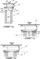
Fig. 2 is a schematic cutaway view of a filter assembly for the gas turbine engine ofFig. 1 in accordance with one embodiment; -
Fig. 3 is an enlarged view of a portion ofFig. 2 ; -
Fig. 4 is a schematic top view of a housing of the filter assembly ofFig. 2 ; -
Fig. 5 is a schematic cutaway partially exploded view of the filter assembly ofFig. 2 ; -
Fig. 6 is a schematic cutaway three dimensional view of a bottom portion of the filter assembly ofFig. 2 ; -
Fig. 7 is a schematic bottom view of a filter cover of a cartridge assembly in accordance with one embodiment; -
Fig. 8 is a schematic top three dimensional view of a filter cartridge that may be used with the filter cover ofFig. 7 ; -
Figs. 9a to 9c are schematic cutaway views of the cartridge assembly ofFigs. 7-8 illustrating steps to assemble the cartridge assembly; -
Fig. 10 is a schematic bottom view of a filter cover in accordance with another embodiment; -
Fig. 11 is a schematic bottom view of a filter cover in accordance with another embodiment; -
Fig. 12 is a schematic three dimensional view of a cartridge assembly in accordance with another embodiment; -
Fig. 13 is a schematic cutaway three dimensional view of the cartridge assembly ofFig. 12 ; -
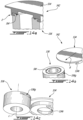
Fig. 14a to 14c are respectively schematic three dimensional cutaway view; schematic top three dimensional exploded view; and schematic bottom three dimensional exploded view of a filter cartridge assembly in accordance with another embodiment illustrating steps to assemble the filter cartridge assembly; -
Figs. 15a to 15c are respectively schematic assembled top three dimensional view; schematic partially assembled top three dimensional view; and schematic assembled cutaway view a filter cartridge assembly in accordance with another embodiment illustrating steps to assemble the filter cartridge assembly. -
Fig. 1 illustrates agas turbine engine 10 of a type preferably provided for use in subsonic flight, generally comprising in serial flow communication afan 12 through which ambient air is propelled, acompressor section 14 for pressurizing the air, acombustor 16 in which the compressed air is mixed with fuel and ignited for generating an annular stream of hot combustion gases, and aturbine section 18 for extracting energy from the combustion gases. Thefan 12, thecompressor section 14, and theturbine section 18 are rotatable about acentral axis 11 of thegas turbine engine 10. - The
gas turbine engine 10 may include a lubrication system S that may include a pump (not shown),lubrication conduits 20, a lubricant reservoir (not shown), and afilter assembly 30. The lubrication system S may also include additional components such as valve(s) (not shown), heat exchangers, etc. The lubricant reservoir may be in fluid flow communication with one or more components of theengine 10 in need of lubrication, such as, for instance, bearing cavity(ies), gearbox(es), and so on. The pump induces a flow of the lubricant from the lubricant reservoir, to the one or more components of theengine 10 in need of lubrication, back from the one or more components toward the reservoir and through thefilter assembly 30. Thefilter assembly 30 is used to remove contaminants from the lubricant before flowing the lubricant towards the one or more components. - In some configurations, a lubricant filter assembly, which includes a filter cartridge and a housing containing the filter cartridge, are secured to a gas turbine engine in such a way that replacement of the filter cartridge includes pulling the whole filter assembly downward. However, in some other configurations, the location of the lubricant filter assembly is such that there is no room to allow the lubricant filter cartridge to be moved downwardly and must be changed from a top. Moreover, care should be taken to ensure that there are no debris that falls into a clean lubricant outlet of the filter assembly when changing the filter cartridge. There is disclosed herein a filter assembly that may alleviate at least some of the aforementioned problems. More specifically, the disclosed filter assembly uses a filter housing defining a lower section for receiving the filter cartridge and an upper section for receiving a filter cover that is securable to the filter housing and to the filter cartridge. The upper section has a greater diameter than that of the lower section for creating a shoulder against which the filter cover abuts. A keyway engagement may be defined between the filter cartridge and the filter cover to secure the filter cartridge to the filter cover and to create a sealing engagement therebetween.
- The clean lubricant outlet of the filter housing may be defined through a peripheral wall of the filter housing. This may prevent debris from falling into said outlet since the outlet may be out of reach of the debris that would fall vertically with gravity upon removal of the filter cartridge and filter cover.
- Referring now to
Figs. 2-4 , thefilter assembly 30 is shown in greater detail. In the embodiment shown, thefilter assembly 30 includes afilter housing 32, afilter cover 34, and afilter cartridge 36. Thefilter cartridge 36 may be removably secured to thefilter cover 34. Thefilter housing 32 is configured to contain thefilter cartridge 36 and thefilter cover 34 is configured to sealingly engage thefilter housing 32 to create a filter internal volume, or cavity, C within which the lubricant circulates through thefilter cartridge 36; thefilter cartridge 36 being contain within the filter internal volume C of thefilter housing 32. In the depicted embodiment, thefilter assembly 30 has a generally cylindrical shape and extends about a longitudinal axis L. - The
filter housing 32, referred simply ashousing 32 herein below, is configured to receive thefilter cartridge 36 therein. Thefilter housing 32 has an inlet (not shown) configured for receiving lubricant to be filtered and has anoutlet 32a for outputting a flow of filtered lubricant. Thehousing 32 has anupper section 32b (Fig. 3 ) and alower section 32c (Fig. 2 ). Thelower section 32c is configured to receive a major portion, that is more than half herein, of thefilter cartridge 36. Theoutlet 32a of thehousing 32 is defined at theupper section 32b of thehousing 32. - In the embodiment shown, the
housing 32 has acircumferential wall 32d and anend wall 32e secured to an end of thecircumferential wall 32d. Thecircumferential wall 32d extends circumferentially around the longitudinal axis L of thefilter assembly 30 and may be cylindrical. Theoutlet 32a of thehousing 32 is defined through thecircumferential wall 32d at theupper section 32b of thehousing 32. Having theoutlet 32a of thehousing 32 locating as such may avoid contaminant to fall into theoutlet 32a upon removal of thefilter cover 34 andfilter cartridge 36 during maintenance and replacement of thefilter cartridge 36. - As shown more clearly in
Figs. 3-4 , theoutlet 32a of thehousing 32 is hydraulically connected with aline 40, which may be part of thehousing 32. Theline 40 may extend substantially perpendicularly to thecircumferential wall 32d of thehousing 32 such that the lubricant exits thefilter assembly 30 in a radial direction, depicted by arrow A onFigs. 3-4 , relative to the longitudinal axis L. Alternatively, theline 40 may define an angle different than 90 degrees relative to thecircumferential wall 32d of thehousing 32. Arrows A' and A" inFigs. 3-4 show that theline 40, and the flow of lubricant exiting thefilter housing 32, may circulate in a radial direction combined with an axial and/or a circumferential direction relative to the longitudinal axis L. The angle theline 40 defines with respect to thehousing 32 may depend upon a location where thefilter assembly 30 is installed in theengine 10. - Still referring to
Figs. 3-4 , thehousing 32 defines ashoulder 32s at an intersection between the upper andlower sections housing 32. In the embodiment shown, a diameter D1 of theupper section 32b is greater than a diameter D2 of thelower section 32c thereby creating theshoulder 32s. As shown inFig. 4 , the upper andlower sections housing 32 may be cylindrical and may be radially offset from one another. In other words, the upper andlower sections lower sections lower sections housing 32 may create additional space to slide thecartridge 36, when saidcartridge 36 is secured to thecover 34, within thehousing 32. This space may be obtained by having the upper andlower sections housing 32 being concentric and by increasing a diameter of theupper section 32b relative to that of thelower section 32c. In a particular embodiment, this offset between the upper andlower sections housing 32 creates the shoulder near the outlet of the housing and may help in protecting the outlet from contaminants that may be released during removal of the filter assembly. - Referring more particularly to
Fig. 2 , thefilter cartridge 36 may include any suitable filtering medium known in the art. In the embodiment shown, thefilter cartridge 36 has an annular shape and has anouter wall 36a, aninner wall 36b located radially inwardly of theouter wall 36a relative to the longitudinal axis L of thefilter assembly 30. Herein, both the outer andinner walls inner walls filter cartridge 36 may define acentral passage 36c that may extend from alower end 36d to anupper end 36e of thefilter cartridge 36. Thefilter cartridge 36 has an inlet 36i and an outlet 36o. In the embodiment shown, the inlet 36i of thefilter cartridge 36 corresponds to theouter wall 36a, such that the lubricant enters in thefilter cartridge 36 in a substantially radial direction relative to the longitudinal axis L of thefilter assembly 30, and the outlet 36o of thefilter cartridge 36 corresponds to thecentral passage 36c at theupper end 36e of thefilter cartridge 36, such that the lubricant exits thefilter cartridge 36 in a substantially axial direction relative to the longitudinal axis of thefilter assembly 30. It is understood that the expressions "upper" and "lower" may be interchanged and that the disclosedfilter 30 may be used upside down, or at any other angle. - A
plug 38 is secured to thefilter cartridge 36 at thelower end 36d thereof. Theplug 38 may be used to prevent lubricant to enter thefilter cartridge 36 via an annular end face located at thelower end 36d of thefilter cartridge 36. In other words, theplug 38 may be used to prevent the lubricant from entering thefilter cartridge 36 in a substantially axial direction. Theplug 38 may ensure that the oil passes through thefilter cartridge 36. Stated differently, theplug 38 may prevent lubricant from penetrating the seal from an axial end face of thecartridge 36. Thefilter cartridge 36 may be free of theplug 38 by having thefilter cartridge 36 in abutment against a bottom of thehousing 32 to avoid oil from bypassing thecartridge 36. As shown more clearly onFig. 6 , aannular groove 38a is defined by theplug 38 and may be configured for receiving a seal, such as an O-ring or any other suitable sealing member, therein. - Referring to
Figs. 3 and5 , for installing acartridge assembly 42 of thefilter cover 34 and thefilter cartridge 36 inside thefilter housing 32, thecartridge assembly 42 is inserted into thehousing 32 substantially along an axial direction relative to the longitudinal axis L via anopen end 32f (Fig. 5 ) of thefilter housing 32. Thecartridge assembly 42 is moved relative to thefilter housing 32 along the axial direction toward theend wall 32e (Fig. 5 ) of thefilter housing 32 until thecover 34 is in abutment against theshoulder 32s (Fig. 5 ) defined by thehousing 32. - As shown in
Fig. 5 , thefilter cover 34 has anannular flange 34a at a top end thereof and thefilter housing 32 has anannular flange 32g at theopen end 32f thereof. Once thecartridge assembly 42 is received within thefilter housing 32, theannular flanges housing 32 and cover 34 may be secured to one another to hold thecartridge assembly 42 in place relative to thefilter housing 32. Any suitable means to secure theannular flanges annular flanges annular flanges cover 34 to thehousing 32 in order to reduce the chances of FOD. A quick release latch for a tool may be used to secure thecover 34 to thehousing 32. - Alternatively, or in combination, a sealing engagement may be created between the
cover 34 and thehousing 32 at a location proximate theshoulder 32s of thehousing 32. As shown inFig. 5 , anannular groove 34b is defined by thecover 34 at a lower end thereof and extends substantially all around the longitudinal axis L. Theannular groove 34b is configured to receive a sealing member, such as an O-ring (not shown), therein. In the embodiment shown, theannular groove 34b faces the radial direction such that the sealing member received therein may be compressed radially between thecover 34 and theperipheral wall 32d of thehousing 32. Alternatively, theannular groove 34b may be defined at an axial end face of thecover 34 such that theannular groove 34b faces the axial direction and faces theshoulder 32s of thehousing 32 such that the sealing member received within theannular groove 34b is compressed axially between the housing at theshoulder 32s and thecover 34. Thecover 34 may define two annular grooves each receiving a respective one of two sealing members; the two annular grooves facing respectively in the radial and axial directions relative to the longitudinal axis L. - Referring more particularly to
Fig. 3 , thecover 34 may be used to change a direction of the lubricant from being substantially axial relative to the longitudinal axis L to being substantial radial. As aforementioned, the lubricant exits thefilter cartridge 36 via its outlet 36o along a direction that is substantially axial and theoutlet 32a of thefilter housing 32 is defined through theperipheral wall 32d and may have at least a radial component relative to the longitudinal axis L. In the embodiment shown, thecover 34 is used to redirect the flow of lubricant from being substantially axial to being substantially radial. Thefilter cover 34 may be used to impart at least a radial and/or at least a circumferential component to the flow of lubricant. - In the depicted embodiment, the
cover 34 has aninternal passage 34c that fluidly connects an inlet 34i of thecover 34 to an outlet 34o thereof. The inlet 34i of thecover 34 is in fluid communication with the outlet 36o of thefilter cartridge 36 and the outlet 34o of thecover 34 is in fluid communication with theoutlet 32a of thehousing 32 and with theline 40 that extends therefrom. Theinternal passage 34c may be defined by two bores extending partially through a body of thecover 34. Herein, theinternal passage 34c includes: a first bore extending substantially axially relative to the longitudinal axis L from the outlet 36o of thefilter cartridge 36 toward a top end of thecover 34 without extending fully through thecover 34; and a second bore extending from the outlet 34o of thecover 34 in a substantially radial direction to a distal end of the first bore such that the first and second bore are in fluid communication with one another. Other configurations are contemplated. The shape of theinternal passage 34c and its orientation inside the cover may vary, including straight holes, smooth cores. - The circulation of the lubricant through the
filter assembly 30 is depicted with arrows inFig. 2 . The lubricant enters the internal volume C defined by thefilter housing 32 and passes through thefilter cartridge 36 in a substantially radial direction relative to the longitudinal axis L and toward the longitudinal axis L to reach thecentral passage 36c of the filter cartridge. The lubricant flows axially along thecentral passage 36 toward thecover 34, enters theinternal passage 34c of thecover 34 in a substantially axial direction and is re-oriented, within theinternal passage 34c of thecover 34, in a direction having at least a radial component relative to the longitudinal axis L. The lubricant exits thefilter assembly 30 via theoutlet 32a of thehousing 32 and is directed toward other components indeed of lubrication via theline 40 that is hydraulically connected to thehousing 32. - With time, the
filter cartridge 36 may decrease in efficiency and may become partially clog by the contaminants it has removed from the lubricant circulating therethrough. Consequently, it may be required to periodically disassemble thefilter assembly 30 to replace thefilter cartridge 36. It may be beneficial to remove thecartridge assembly 42 as a single unit. - Referring to
Fig. 6 , while removing thefilter cartridge 36 from thehousing 32, care should be taken to avoid contact between thecartridge 36 and the housing to avoid rubbing or scrapping thecartridge 36 against theperipheral wall 32d of thehousing 32 which may cause contaminants picked up by thecartridge 36 to detach therefrom an to fall into thehousing 32. In the embodiment shown, a guidingfeature 50 is secured to an end of thecartridge 36 that is located at the bottom of thehousing 32 upon thecartridge assembly 42 received therein. More specifically, and in the embodiment shown, the guidingfeature 50 is secured to theplug 38 at an external periphery thereof. The guidingfeature 50 may be provided in the form of one or more tab(s) 52 circumferentially distributed about the longitudinal axis L and that bridge a gap G located radially between thefilter cartridge 36 and thehousing 32 relative to the longitudinal axis L. The guidingfeature 50 may therefore limit contacts between thecartridge 36 and thehousing 32. The guiding feature may have various alternative shapes and length. It may be displayed in a circular pattern, or it can be a plate on the whole circumference with slots to allow fluid to pass. - Referring now to
Figs. 7-8 , a cover and a filter cartridge in accordance with another embodiment are shown generally at 134 and 136, respectively. And, referring concurrently toFigs. 9a to 9c that illustrate steps of assembly thecover 134 to thefilter cartridge 136. To create a locking engagement E (Fig. 9c ) between thecover 134 and thefilter cartridge 136, thefilter cartridge 136 defines a tab or aflange 136t that may extend circumferentially around the longitudinal axis L. In the embodiment shown, theflange 136t is located at a distal end of the filter cartridge relative to a distance from theend wall 32e (Fig. 5 ) of the housing 32 (Fig. 5 ) in which thecartridge 136 may be received. Theflange 136t has a thickness t1 (Fig. 9a ) taken along the longitudinal axis L. Theflange 136t is configured to be received within agroove 134g defined by thecover 134. Thegroove 134g is shown in dashed line inFig. 7 . Thegroove 134g may have a depth d1 (Fig. 9a ) taken along the longitudinal axis L and that may corresponds substantially to the thickness t1. As shown more particularly onFig. 7 , thegroove 134g is located axially between anaxial end face 134h of thecover 134 and a lip 134l, which extends partially around the longitudinal axis L. Thegroove 134g extends radially outwardly relative to the longitudinal axis from an edge of thelip 136t. Thecover 134 thereby defines anopening 134m, a periphery of which is depicted inFig. 7 with a dashed line. The periphery of theopening 134m is defined partially by thelip 134t. As shown inFigs. 7-8 , the periphery of theopening 134m has a shape that corresponds substantially to a shape of the periphery of theflange 136t of thefilter cartridge 136. It is understood that the groove and the flange may be defined by the filter cartridge and by the cover in an alternate embodiment without departing from the scope of the present disclosure. In a particular embodiment, theflange 136t may define a chamfer to ease its insertion in the groove. - As shown more specifically in
Figs. 9a and 9b , with continued reference toFigs. 7-8 , to assemble thefilter cartridge 136 to thecover 134, thecartridge 136 and thecover 134 are moved one relative to the other along the longitudinal axis L from a disengaged position shown inFig. 9a until theflange 136t is received through theopening 134m defined by thecover 134, which corresponds to an intermediate position shown inFig. 9b . At which point, a sealing member SM, in this case an o-ring 154, which is received within agroove 136g (Fig. 8 ) of thefilter cartridge 136, becomes biased between thefilter cartridge 136 and theaxial end face 134h of the cover. Thecartridge 136 may be in abutment against theaxial end face 134h of thecover 134 upon the o-ring 154 biased therebetween. The sealing member SM may create a sealing engagement between thecover 134 and thecartridge 136 to limit fluid that circulates through thecentral passage 136c (Fig. 9a ) of thefilter 136 and toward thecover 134 from leaking at an interface between the cover andcartridge - Referring more particularly to
Figs. 9b and 9c , thecover 134 may be moved relative to thecartridge 136 from the intermediary position shown inFig. 9b to a locked position shown inFig. 9c . In the embodiment shown, falling within the wording of the claims, thecover 134 andcartridge 136 are moved one relative to the other along a radial direction R (Fig. 9b ) relative to the longitudinal axis L. In other words, thecover 134 and thecartridge 136 are translated one relative to the other to move them from the intermediary position to the locked position ofFig. 9c . In the locked position, at least a portion of theflange 136t is received within thegroove 134g of thecover 134. This creates the locking engagement E that may limit axial movement of thecover 134 relative to thecartridge 136 along the longitudinal axis L. The cooperation of theflange 136t and thegroove 134g may block axial movements of the cover andcartridge flange 136t becomes sandwiched between the lip 134l of thecover 134 and theaxial end face 134h of thecover 134. In the embodiment shown, in the locked position depicted inFig. 9c , the lip 134l of the cover is slidingly received within agroove 136h defined by the cartridge proximate theflange 136t upon theflange 136t received within thegroove 134g of thecover 134. - In an alternate embodiment falling outside of the wording of the claims, the cover and
cartridge cover 134 and thecartridge 136 are in the locked position, the filter cartridge assembly may be moved within the housing 32 (Fig. 2 ) using a handle 156 (Fig. 9a ) located on top of thecover 134. Other means of manipulating the cartridge assembly are contemplated. - Referring back to
Figs. 7-8 , the shape of theopening 134m is configured to maximize a surface contact, or retention surface, area between the lip 134l and theflange 136t of the cover andcartridge opening 134m defines at least onetooth 134t, twoteeth 134t in the embodiment shown, and at least oneslot 134s, twoslots 134s in the embodiment shown. Correspondingly, theflange 136 may define at least oneslot 136s, two in the embodiment shown, and at least onetooth 136q, twoteeth 136q in the embodiment shown. Theteeth 136q of theflange 136t are slidably received within theslots 134s of theopening 134m and theteeth 134t of theopening 134m are slidingly receive within theslots 136s of theflange 136t. In other words, theopening 134m may have a keyway shape corresponding to a shape of theflange 136t to allow one to be received within the other. In the embodiment shown, theopening 134m and theflange 136t are non-axisymmetric and may define a symmetry plane containing the longitudinal axis L. - Referring now to
Figs. 10-11 , alternative embodiments of the cover are shown generally at 234 and 334, respectively. Thecover cover 134 ofFig. 7 by the shape of theiropening - Referring more particularly to
Fig. 10 , theopening 234m includes first and second curved sections 234m1, 234m2 diametrically opposed to one another; a diameter the first curved section 234m1 being greater than that of the second section 234m2. The first and second sections 234m1, 234m2 are connected via a middle section 234m3. The middle section 234m3 defines two slots 234m4 and two teeth 234m5; the two slots facing one another and the two teeth facing one another. In the embodiment shown, the middle section is tangent to the second section. Other configurations are contemplated. For instance, inFig. 7 , the middle section is straight and a junction between the middle and second sections defines a kink. Referring more particularly toFig. 11 , theopening 334m is similar to theopening 234m described above with reference toFig. 10 , but the middle section 334m3 is free of the teeth and slot. - The different shapes of the opening and corresponding flange may be selected to provide a uniformity of a biasing force exerted by the interaction of the cover and filter cartridge on the sealing member when in the locked position shown in
Fig. 9c . The shape of the opening may dictate a surface area used to retain the filter as well as its disposition near the seal. The shape shown inFig. 10 may offer a larger retaining surface. The teeth may be used as a mean to prevent or limit the rotation of thefilter cartridge 36 relative to thecover 34 should a sliding motion is used to disassemble thecartridge 36 from thecover 34. - Referring to
Figs. 12-13 , a cartridge assembly in accordance with another embodiment is shown generally at 442. Thecartridge assembly 442 includes a cover which may correspond to thecover 134 described above with reference toFig. 7 and afilter cartridge 436 in accordance with another embodiment. In some cases, it may be required to grab thecartridge 436 for either assisting its removal from the housing 32 (Fig. 2 ) and/or to orient it with respect to thecover 134. However, the filtering medium of the cartridge may be soft and grabbing it directly may deform it, which may impair its filtering efficiency. - In the embodiment shown, the
filter cartridge 436 includes at least one, two in the embodiment shown, holdingtabs 436n, each of which may be L-shaped including a radial protrusion 436n1 extending radially away from a proximal end of thecartridge 436 and an axial protrusion 436n2 protruding axially from a distal free end of the radial protrusion 436n1. The axial protrusions 436n2 defines a surface 436n3 against which a user may lay his/her finger to manipulate thefilter cartridge 436. In the embodiment shown, the axial protrusions 436n2 extends axially relative to the longitudinal axis L toward the end wall of the housing 32 (Fig. 2 ) when received therein. As shown inFig. 13 , the holdingtabs 436n are axially offset from theflange 136t andgroove 136h defined by thecartridge 436. - The support or holding
tabs 436n may be used if the pinch (e.g. biasing force) between thefilter cover 134 and the sealing member SM (Fig. 9a ) is high enough to expect a deformation of thefilter cartridge 436 during assembly. Thetabs 436n may ease the grip by hand or tool and may be configured to re-direct the load path outside the filter element (e.g. filtering medium). The support may or may not serve as a filter guiding feature once in the locked position. In other words, the tabs may be in abutment against the wall of the housing to maintain the cartridge concentric with the housing. - Referring to
Figs. 14a to 14c , another embodiment of a cartridge assembly is shown generally at 542. Theassembly 542 includes acover 534 and afilter cartridge 536. In the embodiment shown, thecover 534 defines twotabs 534t that are diametrically opposed to one another and thefilter cartridge 536 defines twogrooves 536g that are diametrically opposed to one another. Each of thetabs 534 of thecover 534 may be slidingly received within a respective one of thegrooves 536g of thecartridge 536. It is understood that the cover may define the grooves and the cartridge may define the tab in an alternate embodiment. -
Figs. 14b and 14c illustrate theassembly 542 in the disengaged position andFig. 14c illustrates the assembly in the locked position in which the sealing member SM is compressed between the cover andcartridge cover 534 and thecartridge 536, the cover and cartridge are moved one relative to the other until thegrooves 536g are in register with thetabs 534t. At which point, the cover and thecartridge tabs 534t within thegrooves 536g. - Referring to
Figs. 15a to 15c , another embodiment of a cartridge assembly is shown generally at 642. Theassembly 642 includes acover 634, acartridge 636, and a locking member also referred to as afork 656. In the embodiment shown, thecover 634 defines anelongated slot 634s dimensioned for receiving thefork 656. Thecartridge 636 defines a tab 636t at an extremity of thecartridge 636. Arecess 636r is defined by thecartridge 636 proximate the tab 636t. Thecover 634 has anopening 634m suitably dimensioned for receiving the tab 636t of thecartridge 636. - To create the locking engagement E between the cover and
cartridge cartridge cartridge 636 is received within theopening 634m of thecover 634. At which point, thefork 656 may be inserted in theelongated slot 634s of thecover 634 in a radial direction R relative to the longitudinal axis L. Thefork 656 thereby locks the tab 636t of thecartridge 636 within thecover 634. More specifically, thefork 656 has an inner dimension suitably dimensioned to be able to be received within therecess 636r of thecartridge 636 and that is less than a diameter of the tab 636t, and has an outer dimension that is greater than a dimension of theopening 634m of thecover 634 such that, upon thefork 656 received within theelongated slot 634s of thecover 634, movement of thecover 634 relative to thefilter cartridge 636 along the longitudinal axis L is limited by thefork 656 and, more specifically, limited by the interaction of thefork 656 with the tab 636t of thecartridge 636 and with anannular flange 634f of thecover 634, which defines theopening 634m of thecover 634. In other words, thefork 656 is configured to be in abutment with both of the tab 636t of thecartridge 636 and with theannular flange 634f of thecover 634 to limit movements of thecover 634 relative to thecartridge 636. - As part of the regular scheduled maintenance of an aircraft turbine engine, the lubricant/fuel filters may have to be replaced. It may be important that the filters are easily accessible as this may minimize the risk of introducing debris into the engine. On a twin engine application, the filter may have to be accessible from both sides of the engine. The disclosed filter assembly may minimize the risk of disassembly or mis-assembly that may lead to improper sealing between the inlet and outlet.
- In some cases, filter upright position may be the most desirable one. The outlet may need to be protected against falling debris and filter contaminants. There may be an interest to ease the maintenance by removing the filter with the filter cover. The disclosed filter assemblies may be able to hide the outlet of the filter into the filter cover; ensure a connection to the engine that may not expose the outlet; and ensure a sub-assembly (e.g., filter cartridge assembly 42) between the filter cartridge and the filter cover that may be required by design to assemble the sub-assembly in the filter housing. These may be achieved by a stepped
filter housing 32; a filter assembly sequence that may include an axial seal and a keyway shape interface; and/or filter guiding features. - A stepped filter housing may allow a filter to be mounted vertically upwards. The cover may transfer the fluid to a horizontal connection located on the outlet bore further from the filter bore. This recess may allow the connection to be protected against the filter contaminants in case contaminants are scraped on the filter housing bore during maintenance. The horizontal orientation may minimize the possibility of introducing dirt back into the engine. This step may be achieved by two concentric or non-concentric bores, or by a stepped bore of different shape. If the filter is mounted near the top of the engine it may be equally accessible from both sides of the engine.
- The filter assembly sequence may ensure a minimized disassembly or mis-assembly risk when installed in the housing while allowing to remove the filter with the filter cover. The filter may feature a keyway-shaped flange and an axial seal. The filter cover may feature a keyway-shape slot and a groove. To assemble, the keyway-shaped flange and groove may be aligned and engaged. The filter may slide transversely to apply an axial load on the seal and to fix the filter on the filter cover. The assembly sequence may ensure the axial seal is loaded and the sub-assembly can only be assembled in the housing if the second step is completed.
- The filter guiding features may ensure the filter is properly assembled and sealed on the filter cover when finally assembled in the housing. If the guiding features are located at the bottom of the filter, they may ensure the filter remains concentric to the filter bore in order to reduce the risk of scraping the contaminant from the filter to the housing outlet when the filter is being removed.
- The stepped housing bore may allow for additional radial space to slide the filter on the cover. The filter guiding feature may ensure the filter remains assembled after final assembly when used with a face seal.
- The disclosed filter assemblies and cartridge assemblies may ease maintainability since securing the outlet from debris may allow to use an upright positioned filter. This may be preferable from a maintenance perspective since the bolts and filter may be directly visible/accessible from the top facilitating their access from both sides of the engine. The disclosed filter assemblies and cartridge assemblies may ease packaging since they may minimize the overall envelope required in the nacelle when mounted near the top and when the nacelle door is located at the top. The disclosed filter assemblies and cartridge assemblies may ease maintenance since they allow to remove the filter with the filter cover which may avoid the use of standard or special tooling to remove the filter.
Claims (13)
- A lubricant filter assembly (30) for an engine (10), comprising:a housing (32) having a longitudinal axis (L) and defining an internal volume (C), the housing (32) having an open end (32f); anda cartridge assembly (42) receivable within the internal volume (C) via the open end (32f) of the housing (32) and securable to the housing (32), the cartridge assembly (42) including a filter cartridge (36) having a generally cylindrical shape extending around the longitudinal axis, a cover (34) removably secured to the filter cartridge (36), and a sealing member (SM) between the cover (34) and the filter cartridge (36), a locking engagement (E) between the cover (34) and the filter cartridge (36) to limit an axial movement of the cover (34) relative to the filter cartridge (36) upon removal of the cartridge assembly (42) from the housing (32),wherein the locking engagement (E) is defined by a cooperation of a groove (134g) defined by one of the cover (34) and the filter cartridge (36) and a tab (136t) defined by the other of the cover (34) and the filter cartridge (36),characterized in thatthe cover (534) and filter cartridge (536) are movable one relative to the other in a radial direction (R) relative to the longitudinal axis (L) into a locked position in which the tab (536t) is at least partially within the groove (534g).
- The lubricant filter assembly (30) of any preceding claim, wherein the sealing member (SM) is biased between the cover (34) and the filter cartridge (36) at the locked position.
- The lubricant filter assembly (30) of any preceding claim, wherein the filter cover (34) defines an internal passage (34c) in fluid communication with an outlet (36o) of the filter cartridge (36) and in fluid communication with an outlet (34o) of the filter assembly (30) defined by the housing (32).
- The lubricant filter assembly (30) of any preceding claim, wherein the housing (32) defines an abutment surface (32s) located within the internal volume (C), the cover (34) in engagement with the abutment surface (32s).
- The lubricant filter assembly (30) of claim 4, wherein a cover sealing member is located between the abutment surface (32s) of the housing (32) and the cover (34), the cover sealing member biased between the abutment surface (32s) and the cover (34).
- The lubricant filter assembly (30) of claim 5, wherein the cover sealing member is received within an annular groove (34b) of the cover (34), the annular groove (34b) circumferentially extending around the longitudinal axis (L).
- The lubricant filter assembly (30) of any preceding claim, comprising an upper section (32b) and a lower section (32c), the upper and lower sections (32b, 32c) being non-concentric.
- The lubricant filter assembly (30) of claim 7, wherein an outlet (32a) of the housing (32) is defined at the upper section (32b) of the housing (32).
- The lubricant filter assembly (30) of claim 8, wherein the housing (32) has a circumferential wall (32d), the outlet (32a) of the housing (32) defined through the circumferential wall (32d) at the upper section (32b) of the housing (32).
- The lubricant filter assembly (30) of claim 9, wherein a circumferential portion of the upper section (32b) extends radially beyond the lower section (32c), the circumferential portion registering with a location where a radial distance between the upper section (32b) and the lower section (32c) is maximal, the outlet (32a) of the housing (32) defined at the circumferential portion.
- The lubricant filter assembly (30) of claim 1, wherein the cover (34) is movable relative to the filter cartridge (36) from a disengaged position in which the tab (136t) and the groove (134g) are disengaged to the locked position, and wherein an axial movement of the cover (34) relative to the filter cartridge (36) relative to the longitudinal axis (L) is limited by the engagement of the groove (134g) and the tab (136t) in the locked position.
- The lubricant filter assembly (30) of any preceding claim, comprising at least one holding tab (436n) comprising a radial protrusion (436n1) extending radially away from a proximal end of the cartridge (436), wherein the at least on holding tab (436n) further comprises an axial protrusion (436n2) protruding axially from a distal end of the radial protrusion (436n1).
- The lubricant filter assembly (30) of claim 12, wherein the axial protrusion (436n2) defines a surface (436n3) sized to be engaged by fingers of a user.
Applications Claiming Priority (1)
| Application Number | Priority Date | Filing Date | Title |
|---|---|---|---|
| US16/778,443 US11369908B2 (en) | 2020-01-31 | 2020-01-31 | Filter assembly for gas turbine engine |
Publications (2)
| Publication Number | Publication Date |
|---|---|
| EP3858455A1 EP3858455A1 (en) | 2021-08-04 |
| EP3858455B1 true EP3858455B1 (en) | 2024-09-18 |
Family
ID=74418361
Family Applications (1)
| Application Number | Title | Priority Date | Filing Date |
|---|---|---|---|
| EP21154429.1A Active EP3858455B1 (en) | 2020-01-31 | 2021-01-29 | Filter assembly for gas turbine engine |
Country Status (3)
| Country | Link |
|---|---|
| US (2) | US11369908B2 (en) |
| EP (1) | EP3858455B1 (en) |
| CA (1) | CA3106781A1 (en) |
Family Cites Families (50)
| Publication number | Priority date | Publication date | Assignee | Title |
|---|---|---|---|---|
| US2463800A (en) | 1945-05-11 | 1949-03-08 | Lawrence A Pate | Filter |
| US4322231A (en) | 1980-06-16 | 1982-03-30 | Farr Company | Filter element locking mechanism |
| US4536200A (en) | 1983-10-03 | 1985-08-20 | Reist Parker C | Gas filter apparatus and method of filtering |
| US4707165A (en) | 1985-03-04 | 1987-11-17 | Aeroquip Corporation | Gas and fluid separator |
| US5531129A (en) | 1994-09-21 | 1996-07-02 | Synectic Technology, Inc. | Apparatus for extracting wear particles from used oil filters |
| US6217755B1 (en) | 1998-01-22 | 2001-04-17 | Donaldson Company, Inc. | In-tank fluid filter with valve assembly |
| US6149703A (en) | 1999-06-10 | 2000-11-21 | Siemens Westinghouse Power Corporation | Fuel system filtering apparatus |
| US6348085B1 (en) | 1999-11-10 | 2002-02-19 | Donaldson Company, Inc. | Filter arrangement and methods |
| US6540914B1 (en) | 2000-04-24 | 2003-04-01 | Vortex International, Llc | Cleanable filter with spinning screen |
| US6398833B1 (en) | 2000-11-06 | 2002-06-04 | Pratt & Whitney Canada Corp. | Air/oil separator |
| ITRE20010065A1 (en) | 2001-06-12 | 2002-12-12 | Ufi Universal Filter Int Spa | LIQUID FILTER FOR VEHICLE COMBUSTION ENGINES |
| DE10151439B4 (en) | 2001-10-18 | 2021-09-23 | Valeo Klimasysteme Gmbh | Filter sealing system for heating / air conditioning devices |
| DE60335528D1 (en) | 2002-03-28 | 2011-02-10 | Entegris Inc | FILTRATION MODULE |
| US7056432B2 (en) | 2003-02-21 | 2006-06-06 | Deere & Company | Tank mounted oil filter assembly |
| KR20060127066A (en) | 2003-12-22 | 2006-12-11 | 도날드슨 캄파니 인코포레이티드 | Filter element having a seal configuration and a method of manufacturing the same |
| US6991665B1 (en) | 2004-02-06 | 2006-01-31 | Graver Technologies, Inc. | Evertible filter wrap with straps |
| US7494017B2 (en) | 2004-05-17 | 2009-02-24 | Parker-Hannifin Corporation | Filter element with off-axis end cap |
| BRPI0617353A2 (en) | 2005-10-11 | 2011-07-26 | Donaldson Co Inc | Air Filter Arrangement, Mounting and Methods |
| US8349180B2 (en) | 2006-09-05 | 2013-01-08 | Pall Corporation | Filter elements and assemblies |
| US8404029B2 (en) | 2007-06-14 | 2013-03-26 | Donaldson Company, Inc. | Crankcase ventilation filter arrangments; components; and, methods |
| EP2829310A1 (en) | 2007-06-26 | 2015-01-28 | Donaldson Company, Inc. | Filtration media pack |
| US8226822B2 (en) | 2009-04-27 | 2012-07-24 | Hamilton Sundstrand Corporation | Combined oil filter and debris monitor |
| FI124913B (en) | 2009-07-08 | 2015-03-31 | Eagle Filters Oy | Gas filtration apparatus and method for manufacturing a gas filtration apparatus |
| US8114196B2 (en) | 2009-08-31 | 2012-02-14 | General Electric Company | Gas turbine inlet filter house cleaning apparatus and method |
| US20110277442A1 (en) | 2010-05-12 | 2011-11-17 | General Electric Company | Seal for Gas Turbine Filter |
| US8845898B2 (en) | 2010-07-07 | 2014-09-30 | Hamilton Sundstrand Corporation | APU fuel filter housing scupper |
| US8973760B2 (en) | 2010-10-01 | 2015-03-10 | Advanced Filtration Systems, Inc | Filter system with fuel-water separator |
| US20120240535A1 (en) | 2011-03-22 | 2012-09-27 | General Electric Company | Filter retaining apparatus |
| GB2491581A (en) | 2011-06-03 | 2012-12-12 | Aaf Ltd | Filter assembly |
| ITRE20110059A1 (en) * | 2011-07-29 | 2013-01-30 | Ufi Innovation Ct Srl | FILTERING UNIT AND RELATIVE FILTER CARTRIDGE |
| US8734572B2 (en) | 2012-04-03 | 2014-05-27 | Bha Altair, Llc | Quick engagement method for gas turbine inlet filter installation and replacement |
| EP2764901A1 (en) | 2013-02-07 | 2014-08-13 | Parker Hannifin Corporation | Keyed thread engagement on spin-on filter element |
| EP3008311A4 (en) | 2013-06-12 | 2016-07-20 | United Technologies Corp | Fuel/oil manifold |
| US9962641B2 (en) | 2014-04-04 | 2018-05-08 | Donaldson Company, Inc. | Filter elements with end cap features; element support assembly; and methods |
| US9782702B2 (en) | 2014-05-22 | 2017-10-10 | Pall Corporation | Filter assemblies, filter elements, and methods for filtering liquids |
| US10434453B2 (en) * | 2014-12-31 | 2019-10-08 | Ingersoll-Rand Company | Compressor system having filter assembly with replaceable filter element holder |
| DE102015208426A1 (en) | 2015-05-06 | 2016-11-10 | Mahle International Gmbh | filtering device |
| US10337600B2 (en) | 2015-06-30 | 2019-07-02 | Sikorsky Aircraft Corporation | Scalable in-situ gear box and powertrain lubricant monitoring systems and methods |
| US10024239B2 (en) | 2015-07-22 | 2018-07-17 | Pratt & Whitney Canada Corp. | Fuel filter and bypass valve arrangement |
| WO2017050369A1 (en) | 2015-09-23 | 2017-03-30 | Volvo Truck Corporation | A filter insert and a filter arrangement |
| CN108136288B (en) | 2015-09-23 | 2021-06-25 | 沃尔沃卡车集团 | Filter Inserts and Filter Devices |
| US10201772B2 (en) | 2016-01-22 | 2019-02-12 | Caterpillar Inc. | Filter element and filter system |
| DE102016012328B4 (en) * | 2016-10-17 | 2019-07-04 | Mann+Hummel Gmbh | Filter device with a round filter element, in particular for gas filtration |
| DE102016012331A1 (en) * | 2016-10-17 | 2018-04-19 | Mann + Hummel Gmbh | Round filter element, in particular for gas filtration |
| DE102016012330A1 (en) * | 2016-10-17 | 2018-04-19 | Mann + Hummel Gmbh | Round filter element, in particular for gas filtration |
| DE102016012325A1 (en) * | 2016-10-17 | 2018-04-19 | Mann + Hummel Gmbh | Round filter element, in particular for gas filtration |
| DE102016012327A1 (en) * | 2016-10-17 | 2018-04-19 | Mann + Hummel Gmbh | Round filter element, in particular for gas filtration |
| US10512865B2 (en) | 2017-02-06 | 2019-12-24 | Bha Altair, Llc | Devices and methods for aligning filters in a holding frame |
| PL3441123T3 (en) | 2017-08-11 | 2020-12-14 | Donaldson Company, Inc. | A spin-on fluid treatment device and methods |
| US11073053B2 (en) | 2018-05-08 | 2021-07-27 | Raytheon Technologies Corporation | Centrifugal debris pre-separator for turbine engine oil filter |
-
2020
- 2020-01-31 US US16/778,443 patent/US11369908B2/en active Active
-
2021
- 2021-01-21 CA CA3106781A patent/CA3106781A1/en active Pending
- 2021-01-29 EP EP21154429.1A patent/EP3858455B1/en active Active
-
2022
- 2022-05-26 US US17/804,132 patent/US11944929B2/en active Active
Also Published As
| Publication number | Publication date |
|---|---|
| EP3858455A1 (en) | 2021-08-04 |
| US20220280892A1 (en) | 2022-09-08 |
| US20210236977A1 (en) | 2021-08-05 |
| US11369908B2 (en) | 2022-06-28 |
| CA3106781A1 (en) | 2021-07-31 |
| US11944929B2 (en) | 2024-04-02 |
Similar Documents
| Publication | Publication Date | Title |
|---|---|---|
| EP3318785B1 (en) | Segmented annular seal | |
| US5921213A (en) | Adapter system for engine flushing apparatus | |
| US11946548B2 (en) | Coil spring carbon face seal | |
| EP3026223A1 (en) | Assembly for plugging an aperture in a body | |
| US5813382A (en) | Oil pan drain port adapter system for engine flushing apparatus | |
| CN111927632B (en) | Lubricating oil sealing structure and aircraft engine | |
| EP4397388A2 (en) | Lubricant filter assembly | |
| US11944929B2 (en) | Filter assembly for gas turbine engine | |
| EP4070872B1 (en) | Filter assembly for gas turbine engine | |
| US12134052B2 (en) | Filter assembly for gas turbine engine | |
| EP3730741A1 (en) | Fluid transfer tube with tool receptacle and corresponding assembly | |
| EP2515014B1 (en) | Butterfly valve | |
| DE69621906T2 (en) | gas turbine | |
| US9791047B2 (en) | Magnetic seal system with internal cooling | |
| JP2006090320A (en) | Turbine module for a gas turbine engine having a rotor including a monoblock body | |
| CN115552100A (en) | Lubricant manifold for internal combustion engine | |
| CN109306904A (en) | Air turbine engine-starters | |
| CA2594062A1 (en) | Oil strainer for a gas turbine engine | |
| EP3726009A1 (en) | Assemblies comprising fluid transfer systems | |
| EP4678900A1 (en) | Engine-integrated heat exchanger | |
| CN103670770A (en) | Turbocharger and engine cylinder head assembly | |
| CA3183004A1 (en) | Filter assembly with sedimentation pocket | |
| EP4735144A1 (en) | Filter, filter component, and filter connector system having interlocking tabs and retention elements | |
| EP4036376B1 (en) | Oil-cooled carbon seal |
Legal Events
| Date | Code | Title | Description |
|---|---|---|---|
| PUAI | Public reference made under article 153(3) epc to a published international application that has entered the european phase |
Free format text: ORIGINAL CODE: 0009012 |
|
| STAA | Information on the status of an ep patent application or granted ep patent |
Free format text: STATUS: THE APPLICATION HAS BEEN PUBLISHED |
|
| AK | Designated contracting states |
Kind code of ref document: A1 Designated state(s): AL AT BE BG CH CY CZ DE DK EE ES FI FR GB GR HR HU IE IS IT LI LT LU LV MC MK MT NL NO PL PT RO RS SE SI SK SM TR |
|
| STAA | Information on the status of an ep patent application or granted ep patent |
Free format text: STATUS: REQUEST FOR EXAMINATION WAS MADE |
|
| 17P | Request for examination filed |
Effective date: 20220204 |
|
| RBV | Designated contracting states (corrected) |
Designated state(s): AL AT BE BG CH CY CZ DE DK EE ES FI FR GB GR HR HU IE IS IT LI LT LU LV MC MK MT NL NO PL PT RO RS SE SI SK SM TR |
|
| STAA | Information on the status of an ep patent application or granted ep patent |
Free format text: STATUS: EXAMINATION IS IN PROGRESS |
|
| 17Q | First examination report despatched |
Effective date: 20220513 |
|
| GRAP | Despatch of communication of intention to grant a patent |
Free format text: ORIGINAL CODE: EPIDOSNIGR1 |
|
| STAA | Information on the status of an ep patent application or granted ep patent |
Free format text: STATUS: GRANT OF PATENT IS INTENDED |
|
| INTG | Intention to grant announced |
Effective date: 20240418 |
|
| GRAS | Grant fee paid |
Free format text: ORIGINAL CODE: EPIDOSNIGR3 |
|
| GRAA | (expected) grant |
Free format text: ORIGINAL CODE: 0009210 |
|
| STAA | Information on the status of an ep patent application or granted ep patent |
Free format text: STATUS: THE PATENT HAS BEEN GRANTED |
|
| AK | Designated contracting states |
Kind code of ref document: B1 Designated state(s): AL AT BE BG CH CY CZ DE DK EE ES FI FR GB GR HR HU IE IS IT LI LT LU LV MC MK MT NL NO PL PT RO RS SE SI SK SM TR |
|
| REG | Reference to a national code |
Ref country code: GB Ref legal event code: FG4D |
|
| REG | Reference to a national code |
Ref country code: CH Ref legal event code: EP |
|
| REG | Reference to a national code |
Ref country code: DE Ref legal event code: R096 Ref document number: 602021018825 Country of ref document: DE |
|
| REG | Reference to a national code |
Ref country code: IE Ref legal event code: FG4D |
|
| REG | Reference to a national code |
Ref country code: LT Ref legal event code: MG9D |
|
| PG25 | Lapsed in a contracting state [announced via postgrant information from national office to epo] |
Ref country code: NO Free format text: LAPSE BECAUSE OF FAILURE TO SUBMIT A TRANSLATION OF THE DESCRIPTION OR TO PAY THE FEE WITHIN THE PRESCRIBED TIME-LIMIT Effective date: 20241218 |
|
| PG25 | Lapsed in a contracting state [announced via postgrant information from national office to epo] |
Ref country code: GR Free format text: LAPSE BECAUSE OF FAILURE TO SUBMIT A TRANSLATION OF THE DESCRIPTION OR TO PAY THE FEE WITHIN THE PRESCRIBED TIME-LIMIT Effective date: 20241219 Ref country code: FI Free format text: LAPSE BECAUSE OF FAILURE TO SUBMIT A TRANSLATION OF THE DESCRIPTION OR TO PAY THE FEE WITHIN THE PRESCRIBED TIME-LIMIT Effective date: 20240918 |
|
| PG25 | Lapsed in a contracting state [announced via postgrant information from national office to epo] |
Ref country code: BG Free format text: LAPSE BECAUSE OF FAILURE TO SUBMIT A TRANSLATION OF THE DESCRIPTION OR TO PAY THE FEE WITHIN THE PRESCRIBED TIME-LIMIT Effective date: 20240918 |
|
| PG25 | Lapsed in a contracting state [announced via postgrant information from national office to epo] |
Ref country code: LV Free format text: LAPSE BECAUSE OF FAILURE TO SUBMIT A TRANSLATION OF THE DESCRIPTION OR TO PAY THE FEE WITHIN THE PRESCRIBED TIME-LIMIT Effective date: 20240918 |
|
| PG25 | Lapsed in a contracting state [announced via postgrant information from national office to epo] |
Ref country code: HR Free format text: LAPSE BECAUSE OF FAILURE TO SUBMIT A TRANSLATION OF THE DESCRIPTION OR TO PAY THE FEE WITHIN THE PRESCRIBED TIME-LIMIT Effective date: 20240918 |
|
| REG | Reference to a national code |
Ref country code: NL Ref legal event code: MP Effective date: 20240918 |
|
| PG25 | Lapsed in a contracting state [announced via postgrant information from national office to epo] |
Ref country code: RS Free format text: LAPSE BECAUSE OF FAILURE TO SUBMIT A TRANSLATION OF THE DESCRIPTION OR TO PAY THE FEE WITHIN THE PRESCRIBED TIME-LIMIT Effective date: 20241218 |
|
| PG25 | Lapsed in a contracting state [announced via postgrant information from national office to epo] |
Ref country code: RS Free format text: LAPSE BECAUSE OF FAILURE TO SUBMIT A TRANSLATION OF THE DESCRIPTION OR TO PAY THE FEE WITHIN THE PRESCRIBED TIME-LIMIT Effective date: 20241218 Ref country code: NO Free format text: LAPSE BECAUSE OF FAILURE TO SUBMIT A TRANSLATION OF THE DESCRIPTION OR TO PAY THE FEE WITHIN THE PRESCRIBED TIME-LIMIT Effective date: 20241218 Ref country code: LV Free format text: LAPSE BECAUSE OF FAILURE TO SUBMIT A TRANSLATION OF THE DESCRIPTION OR TO PAY THE FEE WITHIN THE PRESCRIBED TIME-LIMIT Effective date: 20240918 Ref country code: HR Free format text: LAPSE BECAUSE OF FAILURE TO SUBMIT A TRANSLATION OF THE DESCRIPTION OR TO PAY THE FEE WITHIN THE PRESCRIBED TIME-LIMIT Effective date: 20240918 Ref country code: GR Free format text: LAPSE BECAUSE OF FAILURE TO SUBMIT A TRANSLATION OF THE DESCRIPTION OR TO PAY THE FEE WITHIN THE PRESCRIBED TIME-LIMIT Effective date: 20241219 Ref country code: FI Free format text: LAPSE BECAUSE OF FAILURE TO SUBMIT A TRANSLATION OF THE DESCRIPTION OR TO PAY THE FEE WITHIN THE PRESCRIBED TIME-LIMIT Effective date: 20240918 Ref country code: BG Free format text: LAPSE BECAUSE OF FAILURE TO SUBMIT A TRANSLATION OF THE DESCRIPTION OR TO PAY THE FEE WITHIN THE PRESCRIBED TIME-LIMIT Effective date: 20240918 |
|
| REG | Reference to a national code |
Ref country code: AT Ref legal event code: MK05 Ref document number: 1724206 Country of ref document: AT Kind code of ref document: T Effective date: 20240918 |
|
| PG25 | Lapsed in a contracting state [announced via postgrant information from national office to epo] |
Ref country code: NL Free format text: LAPSE BECAUSE OF FAILURE TO SUBMIT A TRANSLATION OF THE DESCRIPTION OR TO PAY THE FEE WITHIN THE PRESCRIBED TIME-LIMIT Effective date: 20240918 |
|
| PG25 | Lapsed in a contracting state [announced via postgrant information from national office to epo] |
Ref country code: PT Free format text: LAPSE BECAUSE OF FAILURE TO SUBMIT A TRANSLATION OF THE DESCRIPTION OR TO PAY THE FEE WITHIN THE PRESCRIBED TIME-LIMIT Effective date: 20250120 Ref country code: IS Free format text: LAPSE BECAUSE OF FAILURE TO SUBMIT A TRANSLATION OF THE DESCRIPTION OR TO PAY THE FEE WITHIN THE PRESCRIBED TIME-LIMIT Effective date: 20250118 |
|
| PG25 | Lapsed in a contracting state [announced via postgrant information from national office to epo] |
Ref country code: RO Free format text: LAPSE BECAUSE OF FAILURE TO SUBMIT A TRANSLATION OF THE DESCRIPTION OR TO PAY THE FEE WITHIN THE PRESCRIBED TIME-LIMIT Effective date: 20240918 Ref country code: SM Free format text: LAPSE BECAUSE OF FAILURE TO SUBMIT A TRANSLATION OF THE DESCRIPTION OR TO PAY THE FEE WITHIN THE PRESCRIBED TIME-LIMIT Effective date: 20240918 |
|
| PG25 | Lapsed in a contracting state [announced via postgrant information from national office to epo] |
Ref country code: ES Free format text: LAPSE BECAUSE OF FAILURE TO SUBMIT A TRANSLATION OF THE DESCRIPTION OR TO PAY THE FEE WITHIN THE PRESCRIBED TIME-LIMIT Effective date: 20240918 |
|
| PG25 | Lapsed in a contracting state [announced via postgrant information from national office to epo] |
Ref country code: EE Free format text: LAPSE BECAUSE OF FAILURE TO SUBMIT A TRANSLATION OF THE DESCRIPTION OR TO PAY THE FEE WITHIN THE PRESCRIBED TIME-LIMIT Effective date: 20240918 Ref country code: AT Free format text: LAPSE BECAUSE OF FAILURE TO SUBMIT A TRANSLATION OF THE DESCRIPTION OR TO PAY THE FEE WITHIN THE PRESCRIBED TIME-LIMIT Effective date: 20240918 |
|
| PG25 | Lapsed in a contracting state [announced via postgrant information from national office to epo] |
Ref country code: CZ Free format text: LAPSE BECAUSE OF FAILURE TO SUBMIT A TRANSLATION OF THE DESCRIPTION OR TO PAY THE FEE WITHIN THE PRESCRIBED TIME-LIMIT Effective date: 20240918 Ref country code: PL Free format text: LAPSE BECAUSE OF FAILURE TO SUBMIT A TRANSLATION OF THE DESCRIPTION OR TO PAY THE FEE WITHIN THE PRESCRIBED TIME-LIMIT Effective date: 20240918 |
|
| PG25 | Lapsed in a contracting state [announced via postgrant information from national office to epo] |
Ref country code: IT Free format text: LAPSE BECAUSE OF FAILURE TO SUBMIT A TRANSLATION OF THE DESCRIPTION OR TO PAY THE FEE WITHIN THE PRESCRIBED TIME-LIMIT Effective date: 20240918 Ref country code: SK Free format text: LAPSE BECAUSE OF FAILURE TO SUBMIT A TRANSLATION OF THE DESCRIPTION OR TO PAY THE FEE WITHIN THE PRESCRIBED TIME-LIMIT Effective date: 20240918 |
|
| REG | Reference to a national code |
Ref country code: DE Ref legal event code: R097 Ref document number: 602021018825 Country of ref document: DE |
|
| PG25 | Lapsed in a contracting state [announced via postgrant information from national office to epo] |
Ref country code: DK Free format text: LAPSE BECAUSE OF FAILURE TO SUBMIT A TRANSLATION OF THE DESCRIPTION OR TO PAY THE FEE WITHIN THE PRESCRIBED TIME-LIMIT Effective date: 20240918 |
|
| PLBE | No opposition filed within time limit |
Free format text: ORIGINAL CODE: 0009261 |
|
| STAA | Information on the status of an ep patent application or granted ep patent |
Free format text: STATUS: NO OPPOSITION FILED WITHIN TIME LIMIT |
|
| 26N | No opposition filed |
Effective date: 20250619 |
|
| REG | Reference to a national code |
Ref country code: CH Ref legal event code: PL |
|
| PG25 | Lapsed in a contracting state [announced via postgrant information from national office to epo] |
Ref country code: SE Free format text: LAPSE BECAUSE OF FAILURE TO SUBMIT A TRANSLATION OF THE DESCRIPTION OR TO PAY THE FEE WITHIN THE PRESCRIBED TIME-LIMIT Effective date: 20240918 |
|
| PG25 | Lapsed in a contracting state [announced via postgrant information from national office to epo] |
Ref country code: MC Free format text: LAPSE BECAUSE OF FAILURE TO SUBMIT A TRANSLATION OF THE DESCRIPTION OR TO PAY THE FEE WITHIN THE PRESCRIBED TIME-LIMIT Effective date: 20240918 Ref country code: LU Free format text: LAPSE BECAUSE OF NON-PAYMENT OF DUE FEES Effective date: 20250129 |
|
| PG25 | Lapsed in a contracting state [announced via postgrant information from national office to epo] |
Ref country code: BE Free format text: LAPSE BECAUSE OF NON-PAYMENT OF DUE FEES Effective date: 20250131 |
|
| PG25 | Lapsed in a contracting state [announced via postgrant information from national office to epo] |
Ref country code: CH Free format text: LAPSE BECAUSE OF NON-PAYMENT OF DUE FEES Effective date: 20250131 |
|
| REG | Reference to a national code |
Ref country code: BE Ref legal event code: MM Effective date: 20250131 |
|
| PGFP | Annual fee paid to national office [announced via postgrant information from national office to epo] |
Ref country code: GB Payment date: 20251220 Year of fee payment: 6 |
|
| PGFP | Annual fee paid to national office [announced via postgrant information from national office to epo] |
Ref country code: FR Payment date: 20251217 Year of fee payment: 6 |
|
| PG25 | Lapsed in a contracting state [announced via postgrant information from national office to epo] |
Ref country code: IE Free format text: LAPSE BECAUSE OF NON-PAYMENT OF DUE FEES Effective date: 20250129 |
|
| PGFP | Annual fee paid to national office [announced via postgrant information from national office to epo] |
Ref country code: DE Payment date: 20251217 Year of fee payment: 6 |