EP3858318A1 - Absorbent article - Google Patents
Absorbent article Download PDFInfo
- Publication number
- EP3858318A1 EP3858318A1 EP19867461.6A EP19867461A EP3858318A1 EP 3858318 A1 EP3858318 A1 EP 3858318A1 EP 19867461 A EP19867461 A EP 19867461A EP 3858318 A1 EP3858318 A1 EP 3858318A1
- Authority
- EP
- European Patent Office
- Prior art keywords
- friction
- absorbent article
- absorbing part
- friction reducing
- sheet
- Prior art date
- Legal status (The legal status is an assumption and is not a legal conclusion. Google has not performed a legal analysis and makes no representation as to the accuracy of the status listed.)
- Granted
Links
Images




Classifications
-
- A—HUMAN NECESSITIES
- A61—MEDICAL OR VETERINARY SCIENCE; HYGIENE
- A61F—FILTERS IMPLANTABLE INTO BLOOD VESSELS; PROSTHESES; DEVICES PROVIDING PATENCY TO, OR PREVENTING COLLAPSING OF, TUBULAR STRUCTURES OF THE BODY, e.g. STENTS; ORTHOPAEDIC, NURSING OR CONTRACEPTIVE DEVICES; FOMENTATION; TREATMENT OR PROTECTION OF EYES OR EARS; BANDAGES, DRESSINGS OR ABSORBENT PADS; FIRST-AID KITS
- A61F13/00—Bandages or dressings; Absorbent pads
- A61F13/15—Absorbent pads, e.g. sanitary towels, swabs or tampons for external or internal application to the body; Supporting or fastening means therefor; Tampon applicators
- A61F13/56—Supporting or fastening means
-
- A—HUMAN NECESSITIES
- A61—MEDICAL OR VETERINARY SCIENCE; HYGIENE
- A61F—FILTERS IMPLANTABLE INTO BLOOD VESSELS; PROSTHESES; DEVICES PROVIDING PATENCY TO, OR PREVENTING COLLAPSING OF, TUBULAR STRUCTURES OF THE BODY, e.g. STENTS; ORTHOPAEDIC, NURSING OR CONTRACEPTIVE DEVICES; FOMENTATION; TREATMENT OR PROTECTION OF EYES OR EARS; BANDAGES, DRESSINGS OR ABSORBENT PADS; FIRST-AID KITS
- A61F13/00—Bandages or dressings; Absorbent pads
- A61F13/15—Absorbent pads, e.g. sanitary towels, swabs or tampons for external or internal application to the body; Supporting or fastening means therefor; Tampon applicators
- A61F13/45—Absorbent pads, e.g. sanitary towels, swabs or tampons for external or internal application to the body; Supporting or fastening means therefor; Tampon applicators characterised by the shape
- A61F13/47—Sanitary towels, incontinence pads or napkins
- A61F13/472—Sanitary towels, incontinence pads or napkins specially adapted for female use
-
- A—HUMAN NECESSITIES
- A61—MEDICAL OR VETERINARY SCIENCE; HYGIENE
- A61F—FILTERS IMPLANTABLE INTO BLOOD VESSELS; PROSTHESES; DEVICES PROVIDING PATENCY TO, OR PREVENTING COLLAPSING OF, TUBULAR STRUCTURES OF THE BODY, e.g. STENTS; ORTHOPAEDIC, NURSING OR CONTRACEPTIVE DEVICES; FOMENTATION; TREATMENT OR PROTECTION OF EYES OR EARS; BANDAGES, DRESSINGS OR ABSORBENT PADS; FIRST-AID KITS
- A61F13/00—Bandages or dressings; Absorbent pads
- A61F13/15—Absorbent pads, e.g. sanitary towels, swabs or tampons for external or internal application to the body; Supporting or fastening means therefor; Tampon applicators
- A61F13/51—Absorbent pads, e.g. sanitary towels, swabs or tampons for external or internal application to the body; Supporting or fastening means therefor; Tampon applicators characterised by the outer layers of the pads
- A61F13/511—Topsheet, i.e. the permeable cover or layer facing the skin
- A61F13/513—Topsheet, i.e. the permeable cover or layer facing the skin characterised by its function or properties, e.g. stretchability, breathability, rewet, visual effect; having areas of different permeability
-
- A—HUMAN NECESSITIES
- A61—MEDICAL OR VETERINARY SCIENCE; HYGIENE
- A61F—FILTERS IMPLANTABLE INTO BLOOD VESSELS; PROSTHESES; DEVICES PROVIDING PATENCY TO, OR PREVENTING COLLAPSING OF, TUBULAR STRUCTURES OF THE BODY, e.g. STENTS; ORTHOPAEDIC, NURSING OR CONTRACEPTIVE DEVICES; FOMENTATION; TREATMENT OR PROTECTION OF EYES OR EARS; BANDAGES, DRESSINGS OR ABSORBENT PADS; FIRST-AID KITS
- A61F13/00—Bandages or dressings; Absorbent pads
- A61F13/15—Absorbent pads, e.g. sanitary towels, swabs or tampons for external or internal application to the body; Supporting or fastening means therefor; Tampon applicators
- A61F13/51—Absorbent pads, e.g. sanitary towels, swabs or tampons for external or internal application to the body; Supporting or fastening means therefor; Tampon applicators characterised by the outer layers of the pads
- A61F13/514—Backsheet, i.e. the impermeable cover or layer furthest from the skin
- A61F13/51474—Backsheet, i.e. the impermeable cover or layer furthest from the skin characterised by its structure
-
- A—HUMAN NECESSITIES
- A61—MEDICAL OR VETERINARY SCIENCE; HYGIENE
- A61F—FILTERS IMPLANTABLE INTO BLOOD VESSELS; PROSTHESES; DEVICES PROVIDING PATENCY TO, OR PREVENTING COLLAPSING OF, TUBULAR STRUCTURES OF THE BODY, e.g. STENTS; ORTHOPAEDIC, NURSING OR CONTRACEPTIVE DEVICES; FOMENTATION; TREATMENT OR PROTECTION OF EYES OR EARS; BANDAGES, DRESSINGS OR ABSORBENT PADS; FIRST-AID KITS
- A61F13/00—Bandages or dressings; Absorbent pads
- A61F13/15—Absorbent pads, e.g. sanitary towels, swabs or tampons for external or internal application to the body; Supporting or fastening means therefor; Tampon applicators
- A61F13/51—Absorbent pads, e.g. sanitary towels, swabs or tampons for external or internal application to the body; Supporting or fastening means therefor; Tampon applicators characterised by the outer layers of the pads
- A61F13/514—Backsheet, i.e. the impermeable cover or layer furthest from the skin
- A61F13/51474—Backsheet, i.e. the impermeable cover or layer furthest from the skin characterised by its structure
- A61F13/51478—Backsheet, i.e. the impermeable cover or layer furthest from the skin characterised by its structure being a laminate, e.g. multi-layered or with several layers
-
- A—HUMAN NECESSITIES
- A61—MEDICAL OR VETERINARY SCIENCE; HYGIENE
- A61F—FILTERS IMPLANTABLE INTO BLOOD VESSELS; PROSTHESES; DEVICES PROVIDING PATENCY TO, OR PREVENTING COLLAPSING OF, TUBULAR STRUCTURES OF THE BODY, e.g. STENTS; ORTHOPAEDIC, NURSING OR CONTRACEPTIVE DEVICES; FOMENTATION; TREATMENT OR PROTECTION OF EYES OR EARS; BANDAGES, DRESSINGS OR ABSORBENT PADS; FIRST-AID KITS
- A61F13/00—Bandages or dressings; Absorbent pads
- A61F13/15—Absorbent pads, e.g. sanitary towels, swabs or tampons for external or internal application to the body; Supporting or fastening means therefor; Tampon applicators
- A61F13/51—Absorbent pads, e.g. sanitary towels, swabs or tampons for external or internal application to the body; Supporting or fastening means therefor; Tampon applicators characterised by the outer layers of the pads
- A61F13/514—Backsheet, i.e. the impermeable cover or layer furthest from the skin
- A61F13/51498—Details not otherwise provided for
-
- A—HUMAN NECESSITIES
- A61—MEDICAL OR VETERINARY SCIENCE; HYGIENE
- A61F—FILTERS IMPLANTABLE INTO BLOOD VESSELS; PROSTHESES; DEVICES PROVIDING PATENCY TO, OR PREVENTING COLLAPSING OF, TUBULAR STRUCTURES OF THE BODY, e.g. STENTS; ORTHOPAEDIC, NURSING OR CONTRACEPTIVE DEVICES; FOMENTATION; TREATMENT OR PROTECTION OF EYES OR EARS; BANDAGES, DRESSINGS OR ABSORBENT PADS; FIRST-AID KITS
- A61F13/00—Bandages or dressings; Absorbent pads
- A61F13/15—Absorbent pads, e.g. sanitary towels, swabs or tampons for external or internal application to the body; Supporting or fastening means therefor; Tampon applicators
- A61F13/53—Absorbent pads, e.g. sanitary towels, swabs or tampons for external or internal application to the body; Supporting or fastening means therefor; Tampon applicators characterised by the absorbing medium
- A61F13/534—Absorbent pads, e.g. sanitary towels, swabs or tampons for external or internal application to the body; Supporting or fastening means therefor; Tampon applicators characterised by the absorbing medium having an inhomogeneous composition through the thickness of the pad
-
- A—HUMAN NECESSITIES
- A61—MEDICAL OR VETERINARY SCIENCE; HYGIENE
- A61F—FILTERS IMPLANTABLE INTO BLOOD VESSELS; PROSTHESES; DEVICES PROVIDING PATENCY TO, OR PREVENTING COLLAPSING OF, TUBULAR STRUCTURES OF THE BODY, e.g. STENTS; ORTHOPAEDIC, NURSING OR CONTRACEPTIVE DEVICES; FOMENTATION; TREATMENT OR PROTECTION OF EYES OR EARS; BANDAGES, DRESSINGS OR ABSORBENT PADS; FIRST-AID KITS
- A61F13/00—Bandages or dressings; Absorbent pads
- A61F13/15—Absorbent pads, e.g. sanitary towels, swabs or tampons for external or internal application to the body; Supporting or fastening means therefor; Tampon applicators
- A61F13/53—Absorbent pads, e.g. sanitary towels, swabs or tampons for external or internal application to the body; Supporting or fastening means therefor; Tampon applicators characterised by the absorbing medium
- A61F13/534—Absorbent pads, e.g. sanitary towels, swabs or tampons for external or internal application to the body; Supporting or fastening means therefor; Tampon applicators characterised by the absorbing medium having an inhomogeneous composition through the thickness of the pad
- A61F13/535—Absorbent pads, e.g. sanitary towels, swabs or tampons for external or internal application to the body; Supporting or fastening means therefor; Tampon applicators characterised by the absorbing medium having an inhomogeneous composition through the thickness of the pad inhomogeneous in the plane of the pad, e.g. core absorbent layers being of different sizes
-
- A—HUMAN NECESSITIES
- A61—MEDICAL OR VETERINARY SCIENCE; HYGIENE
- A61F—FILTERS IMPLANTABLE INTO BLOOD VESSELS; PROSTHESES; DEVICES PROVIDING PATENCY TO, OR PREVENTING COLLAPSING OF, TUBULAR STRUCTURES OF THE BODY, e.g. STENTS; ORTHOPAEDIC, NURSING OR CONTRACEPTIVE DEVICES; FOMENTATION; TREATMENT OR PROTECTION OF EYES OR EARS; BANDAGES, DRESSINGS OR ABSORBENT PADS; FIRST-AID KITS
- A61F13/00—Bandages or dressings; Absorbent pads
- A61F13/15—Absorbent pads, e.g. sanitary towels, swabs or tampons for external or internal application to the body; Supporting or fastening means therefor; Tampon applicators
- A61F13/53—Absorbent pads, e.g. sanitary towels, swabs or tampons for external or internal application to the body; Supporting or fastening means therefor; Tampon applicators characterised by the absorbing medium
- A61F13/539—Absorbent pads, e.g. sanitary towels, swabs or tampons for external or internal application to the body; Supporting or fastening means therefor; Tampon applicators characterised by the absorbing medium characterised by the connection of the absorbent layers with each other or with the outer layers
-
- A—HUMAN NECESSITIES
- A61—MEDICAL OR VETERINARY SCIENCE; HYGIENE
- A61F—FILTERS IMPLANTABLE INTO BLOOD VESSELS; PROSTHESES; DEVICES PROVIDING PATENCY TO, OR PREVENTING COLLAPSING OF, TUBULAR STRUCTURES OF THE BODY, e.g. STENTS; ORTHOPAEDIC, NURSING OR CONTRACEPTIVE DEVICES; FOMENTATION; TREATMENT OR PROTECTION OF EYES OR EARS; BANDAGES, DRESSINGS OR ABSORBENT PADS; FIRST-AID KITS
- A61F13/00—Bandages or dressings; Absorbent pads
- A61F13/15—Absorbent pads, e.g. sanitary towels, swabs or tampons for external or internal application to the body; Supporting or fastening means therefor; Tampon applicators
- A61F13/51—Absorbent pads, e.g. sanitary towels, swabs or tampons for external or internal application to the body; Supporting or fastening means therefor; Tampon applicators characterised by the outer layers of the pads
- A61F13/514—Backsheet, i.e. the impermeable cover or layer furthest from the skin
- A61F13/51456—Backsheet, i.e. the impermeable cover or layer furthest from the skin characterised by its properties
- A61F2013/5147—Backsheet, i.e. the impermeable cover or layer furthest from the skin characterised by its properties the outer layer being adhesive itself
-
- A—HUMAN NECESSITIES
- A61—MEDICAL OR VETERINARY SCIENCE; HYGIENE
- A61F—FILTERS IMPLANTABLE INTO BLOOD VESSELS; PROSTHESES; DEVICES PROVIDING PATENCY TO, OR PREVENTING COLLAPSING OF, TUBULAR STRUCTURES OF THE BODY, e.g. STENTS; ORTHOPAEDIC, NURSING OR CONTRACEPTIVE DEVICES; FOMENTATION; TREATMENT OR PROTECTION OF EYES OR EARS; BANDAGES, DRESSINGS OR ABSORBENT PADS; FIRST-AID KITS
- A61F13/00—Bandages or dressings; Absorbent pads
- A61F13/15—Absorbent pads, e.g. sanitary towels, swabs or tampons for external or internal application to the body; Supporting or fastening means therefor; Tampon applicators
- A61F13/53—Absorbent pads, e.g. sanitary towels, swabs or tampons for external or internal application to the body; Supporting or fastening means therefor; Tampon applicators characterised by the absorbing medium
- A61F13/534—Absorbent pads, e.g. sanitary towels, swabs or tampons for external or internal application to the body; Supporting or fastening means therefor; Tampon applicators characterised by the absorbing medium having an inhomogeneous composition through the thickness of the pad
- A61F13/537—Absorbent pads, e.g. sanitary towels, swabs or tampons for external or internal application to the body; Supporting or fastening means therefor; Tampon applicators characterised by the absorbing medium having an inhomogeneous composition through the thickness of the pad characterised by a layer facilitating or inhibiting flow in one direction or plane, e.g. a wicking layer
- A61F2013/53765—Absorbent pads, e.g. sanitary towels, swabs or tampons for external or internal application to the body; Supporting or fastening means therefor; Tampon applicators characterised by the absorbing medium having an inhomogeneous composition through the thickness of the pad characterised by a layer facilitating or inhibiting flow in one direction or plane, e.g. a wicking layer characterized by its geometry
- A61F2013/53769—Absorbent pads, e.g. sanitary towels, swabs or tampons for external or internal application to the body; Supporting or fastening means therefor; Tampon applicators characterised by the absorbing medium having an inhomogeneous composition through the thickness of the pad characterised by a layer facilitating or inhibiting flow in one direction or plane, e.g. a wicking layer characterized by its geometry with the wicking layer not contacting the absorbent core
- A61F2013/53773—Absorbent pads, e.g. sanitary towels, swabs or tampons for external or internal application to the body; Supporting or fastening means therefor; Tampon applicators characterised by the absorbing medium having an inhomogeneous composition through the thickness of the pad characterised by a layer facilitating or inhibiting flow in one direction or plane, e.g. a wicking layer characterized by its geometry with the wicking layer not contacting the absorbent core with a deformable spacing structure
-
- A—HUMAN NECESSITIES
- A61—MEDICAL OR VETERINARY SCIENCE; HYGIENE
- A61F—FILTERS IMPLANTABLE INTO BLOOD VESSELS; PROSTHESES; DEVICES PROVIDING PATENCY TO, OR PREVENTING COLLAPSING OF, TUBULAR STRUCTURES OF THE BODY, e.g. STENTS; ORTHOPAEDIC, NURSING OR CONTRACEPTIVE DEVICES; FOMENTATION; TREATMENT OR PROTECTION OF EYES OR EARS; BANDAGES, DRESSINGS OR ABSORBENT PADS; FIRST-AID KITS
- A61F13/00—Bandages or dressings; Absorbent pads
- A61F13/15—Absorbent pads, e.g. sanitary towels, swabs or tampons for external or internal application to the body; Supporting or fastening means therefor; Tampon applicators
- A61F13/84—Accessories, not otherwise provided for, for absorbent pads
- A61F13/8405—Additives, e.g. for odour, disinfectant or pH control
- A61F2013/8455—Additives, e.g. for odour, disinfectant or pH control being lubricants
Definitions
- FIG. 1 is a partially-broken plan view of an absorbent article 1 according to an embodiment of the present invention.
- FIG. 2 (a) is a cross-sectional view taken along line I-I of FIG. 1 .
- the absorbent article 1 includes a body (absorbent article body) 8 including an impermeable back sheet 2, a permeable top sheet 3, and an absorbing part 4 provided between the sheets 2 and 3.
- the absorbent article 1 is worn such that the back sheet 2 (underwear side) of the body 8 is fixed to underwear such as shorts and the top sheet 3 (skin side) contacts the skin.
- An antislip part (not illustrated in FIG. 1 ) for fixing the absorbent article 1 to the underwear may be provided on the underwear side of the back sheet 2.
- the absorbing part 4 may include an absorber 41 that essentially performs the function of absorbing a body fluid and an enveloping sheet 45 that envelopes the absorber 41.
- the material of the enveloping sheet 45 may be, for example, but is not limited to, crepe paper or a nonwoven fabric. Enveloping the absorber 41 with the enveloping sheet 45 makes it possible to prevent the absorber 41 from wrinkling or cracking.
- the enveloping sheet 45 may be implemented by either uncolored (i.e., white) crepe paper or nonwoven fabric or colored crepe paper or nonwoven fabric.
- bonding the back sheet 2 and the absorbing part 4 to each other at the front end of the absorbing part 4 and/or front side-ends of the absorbing part 4 makes the absorbent article 1 less likely to be damaged and makes it possible to stabilize the shape of the absorbent article without reducing the function of the friction reducing layer 6 in the middle region M and the rear region R.
Landscapes
- Health & Medical Sciences (AREA)
- Epidemiology (AREA)
- Engineering & Computer Science (AREA)
- Biomedical Technology (AREA)
- Heart & Thoracic Surgery (AREA)
- Vascular Medicine (AREA)
- Life Sciences & Earth Sciences (AREA)
- Animal Behavior & Ethology (AREA)
- General Health & Medical Sciences (AREA)
- Public Health (AREA)
- Veterinary Medicine (AREA)
- Dermatology (AREA)
- Absorbent Articles And Supports Therefor (AREA)
Abstract
Description
- The present invention relates to an absorbent article.
- Known absorbent articles such as a sanitary napkin, a pantiliner, and an incontinence pad are made by sandwiching an absorbing part between a permeable top sheet and an impermeable back sheet.
- Also, there is an absorbent article that is configured to be deformable according to movement of the body of a wearer. For example,
Patent Document 1 describes a configuration including a shrinkable absorption structure disposed between a front-side sheet and a back-side sheet. The absorption structure includes a large number of block-shaped absorbers that are independent of each other; and the back-side sheet has stretchability at least in the longitudinal direction, is in a contracted state when not stretched, and stretches at a predetermined ratio in the longitudinal direction in response to a predetermined tensile load (e.g., claim 1). - [Patent Document 1]
Japanese Patent No. 5779414 - With the configuration disclosed in
Patent Document 1, the entire absorbent article has stretchability and therefore can expand and contract along with the expansion and contraction of underwear caused by the movement of the body. However, the configuration disclosed inPatent Document 1 does not take into account the friction between the absorbent article and the skin, which may occur when the body of a wearer of the absorbent article moves during, for example, walking. Such friction may reduce the wear comfort and, in some cases, may cause the wearer to feel, for example, itchiness or pain. - In view of the above problems, one object of the present invention is to provide an absorbent article that is more comfortable to wear and configured to prevent friction between the absorbent article and the skin which may occur while the absorbent article is worn.
- According to a first aspect of the present invention, an absorbent article includes a permeable top sheet, an impermeable back sheet, an absorbing part disposed between the top sheet and the back sheet, and a friction reducing layer disposed between the back sheet and the absorbing part. The friction between the friction reducing layer and the back sheet or the friction between the friction reducing layer and the absorbing part is less than the friction between the absorbing part and the back sheet.
- An aspect of the present invention makes it possible to provide an absorbent article that is more comfortable to wear and configured to prevent friction between the absorbent article and the skin which may occur while the absorbent article is worn.
-
-
FIG. 1 is a partially-broken plan view of an absorbent article according to an embodiment of the present invention; -
FIG. 2 is a cross-sectional view taken along line I-I of the absorbed article of the embodiment of the present invention; -
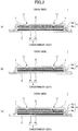
FIG. 3 is a drawing illustrating a variation of a friction reducing layer of the absorbent article according to the embodiment of the present invention; -
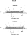
FIG. 4 is a drawing illustrating a variation of a friction reducing layer of the absorbent article according to the embodiment of the present invention; -
FIG. 5 is a drawing illustrating a variation of the absorbent article according to the embodiment of the present invention; and -
FIG. 6 is a drawing illustrating a variation of the absorbent article according to the embodiment of the present invention. - An embodiment of the present invention is described below with reference to the accompanying drawings. Unless otherwise mentioned, the same reference number is assigned to the same component or corresponding components throughout the drawings, and repeated descriptions of those components may be omitted. Also, the drawings are schematic diagrams for facilitating the understanding of the invention, and some dimensions may be greater than or less than the actual dimensions.
-
FIG. 1 is a partially-broken plan view of anabsorbent article 1 according to an embodiment of the present invention.FIG. 2 (a) is a cross-sectional view taken along line I-I ofFIG. 1 . As illustrated inFIG. 1 andFIG. 2(a) , theabsorbent article 1 includes a body (absorbent article body) 8 including animpermeable back sheet 2, apermeable top sheet 3, and an absorbingpart 4 provided between thesheets absorbent article 1 is worn such that the back sheet 2 (underwear side) of thebody 8 is fixed to underwear such as shorts and the top sheet 3 (skin side) contacts the skin. An antislip part (not illustrated inFIG. 1 ) for fixing theabsorbent article 1 to the underwear may be provided on the underwear side of theback sheet 2. - The
absorbent article body 8 is a portion of theabsorbent article 1 excluding wings W described later. As a whole, thebody 8 has an elongated shape that has a predetermined length in the longitudinal direction (the front-back direction, i.e., a first direction D1 in the figure) and a predetermined width in the width direction (a second direction D2 in the figure) orthogonal to the longitudinal direction D1. Although the width of thebody 8 is substantially constant in the illustrated example, the width of thebody 8 may vary along the longitudinal direction D1. Theabsorbent article 1 may have a shape and a structure that are substantially axisymmetric with respect to a center line (longitudinal center line) CL extending in the longitudinal direction. - In the example of
FIG. 1 , both of theback sheet 2 and thetop sheet 3 extend in the longitudinal direction D1 from the front end to the rear end of theabsorbent article 1, and the width of thetop sheet 3 is less than the width of theback sheet 2. Sidenonwoven fabrics 7 extending in the longitudinal direction D1 along the lateral ends of the absorbingpart 4 overlap the skin side of thetop sheet 3. - The
body 8 of theabsorbent article 1 includes a region (body fluid outlet region) A that faces a body fluid outlet such as the vaginal opening of a wearer wearing theabsorbent article 1, and the body fluid outlet region A has a center Ac. The center Ac is located on the longitudinal center line CL and near the center of the body fluid outlet region A in the longitudinal direction D1. Theabsorbent article 1 includes a middle region M including the body fluid outlet region A, a front region F next to the front end of the middle region M, and a rear region R next to the rear end of the middle region M. - The middle region M may include wings W that extend from the lateral sides of the middle region M and are used to reliably fix the
absorbent article 1 to the underwear when theabsorbent article 1 is worn. The front region F extends from positions corresponding to or near the front starting points of the wings W to the front end, and the rear region R extends from positions corresponding to or near the rear starting points of the wings W to the rear end. Also, when the wings W are provided, in the longitudinal direction D1, the center Ac of the body fluid outlet region A may be located in the midpoint in the length of the lateral edges of the wings W or in the midpoint between the front starting points and the rear starting points of the wings W. - Although the
absorbent article 1 in the illustrated example includes the wings W, theabsorbent article 1 may be configured to not include the wings W. In this case, the front region F may be a region extending forward from positions corresponding to or near the front starting points of wings W that are assumed to be formed, and the rear region R may be a region extending backward from positions corresponding to or near the rear starting points of wings W that are assumed to be formed. - The overall length of the
absorbent article 1 is preferably between 150 and 450 mm, and more preferably between 170 and 290 mm. - The absorbing
part 4 is provided between thetop sheet 2 and theback sheet 3 so as not to be exposed to the outside. For example, as illustrated inFIG. 1 , the absorbingpart 4 may be configured and disposed to fit in theback sheet 2 in plan view, i.e., not to extend beyond theback sheet 2. Also, the absorbingpart 4 may be configured and disposed to fit in a region where thetop sheet 3 and the sidenonwoven fabrics 7 are provided. - At the front and rear ends of the absorbing
part 4, end seals Ee may be formed by bonding the outer edges of theback sheet 2 and thetop sheet 3 with an adhesive such as a hot melt or by a bonding technique such as heat sealing or ultrasonic sealing. Also, at the lateral ends of the absorbingpart 4, the sidenonwoven fabrics 7 and theback sheet 2 may be bonded to each other by a bonding technique as described above to form the wings W. Embossments Ew may be formed on the wings W to increase the bonding strength and improve the design. - Thus, the entire periphery of the absorbing
part 4 may be sealed. This makes it possible to prevent a body fluid absorbed by the absorbingpart 4 from leaking from the side of the absorbingpart 4 and also make it possible to improve the shape stability of theabsorbent article 1. The strength of the end seals Ee is preferably greater than that of the side seals. This allows theback sheet 2 and the absorbingpart 4 to slide relative to each other as described later, and also makes it possible to stabilize the shape of theabsorbent article 1. - The
back sheet 2 may be formed of a sheet material having at least a waterproof property such as an olefinic resin sheet made of polyethylene or polypropylene. Also, theback sheet 2 may be implemented by a laminated nonwoven fabric formed by stacking a nonwoven fabric on, for example, a polyethylene sheet, or a laminated sheet that is made substantially impermeable by stacking a waterproof film between nonwoven fabrics. Further, a sheet having moisture permeability is more preferably used to prevent stuffiness. As the water-impermeable and moisture-permeable sheet, a microporous sheet is preferably used. A microporous sheet is obtained by melt-mixing an inorganic filler with an olefin resin such as polyethylene or polypropylene to form a sheet, and by stretching the sheet uniaxially or biaxially. - The
top sheet 3 is a permeable sheet through which body fluids such as blood, discharge, and urine can permeate rapidly. Thetop sheet 3 is preferably formed of a porous or nonporous nonwoven fabric or a porous plastic sheet. The nonwoven fabric may be formed by using one of or a combination of two or more of the following materials: olefins such as polyethylene and polypropylene, synthetic fibers such as polyester and polyamide, regenerated fibers such as rayon and cupra, a blend of these fibers, and natural fibers such as cotton. The nonwoven fabric may be produced by, for example, spunlacing, spunbonding, thermal bonding, melt-blowing, or needle punching. Among these production methods, spunlacing is preferable to produce a flexible nonwoven fabric, spunbonding is preferable to produce a nonwoven fabric with good draping characteristics, and thermal bonding is preferable to produce a bulky and soft nonwoven fabric. Also, bicomponent fibers may be used for the synthetic fibers. Examples of bicomponent fibers include a core-in-sheath fiber including a high-melting-point fiber as a core and a low-melting-point fiber as a sheath, a side-by-side fiber, and a split fiber. - As illustrated in
FIG. 1 , the absorbingpart 4 may include anabsorber 41 that essentially performs the function of absorbing a body fluid and anenveloping sheet 45 that envelopes theabsorber 41. The material of the envelopingsheet 45 may be, for example, but is not limited to, crepe paper or a nonwoven fabric. Enveloping theabsorber 41 with the envelopingsheet 45 makes it possible to prevent theabsorber 41 from wrinkling or cracking. The envelopingsheet 45 may be implemented by either uncolored (i.e., white) crepe paper or nonwoven fabric or colored crepe paper or nonwoven fabric. - The
absorber 41 may be implemented by any material that can absorb and hold a body fluid, and preferably includes cotton pulp and an absorbent polymer. Examples of absorbent polymers include superabsorbent polymer (SAP) granular powder (SAP), superabsorbent fibers (SAF), and a combination of them. Examples of the pulp include chemical pulp obtained from wood, cellulose fibers such as dissolving pulp, and artificial cellulose fibers such as rayon and acetate. Hardwood and softwood may be used as the materials of the chemical pulp, but softwood is preferably used because of its long fiber length. Theabsorber 41 may be produced by fiber stacking or an air-laid method. - Synthetic fibers may also be added to the
absorber 41. Examples of materials of the synthetic fibers include polyolefin such as polyethylene and polypropylene, polyester such as polyethylene terephthalate or polybutylene terephthalate, polyamide such as nylon, and a copolymer of these materials. Also, the synthetic fibers may be formed by mixing two or more of these materials. Also, bicomponent fibers may be used for the synthetic fibers. Examples of bicomponent fibers include a core-in-sheath fiber including a high-melting-point fiber as a core and a low-melting-point fiber as a sheath, a side-by-side fiber, and a split fiber. Further, a material obtained by surface-treating hydrophobic fibers with a hydrophilic agent to have an affinity to body fluids may be used as the synthetic fibers. - The absorbing
part 4 may be implemented by a polymer sheet including a superabsorbent polymer sandwiched in a predetermined region between a skin-side sheet and an underwear-side sheet. - The thickness of the
absorbing part 4 may be between 0.3 and 30 mm, and is preferably between 1.0 and 15 mm. Theabsorber 41 does not necessarily have a uniform thickness in its entirety, and the body fluid outlet region 50, a region near the body fluid outlet region 50, and a central portion of the rear region in the width direction may be bulging. - The
side nonwoven fabrics 7 may be implemented by a water-repellent nonwoven fabric or a hydrophilically-treated nonwoven fabric. For example, a water-repellent nonwoven fabric coated with a silicon- or paraffin-repellent is preferably used to more prevent penetration of body fluids such as blood and discharge or to improve the feel. Also, to improve the absorbency of the wings W for absorbing, for example, menstrual blood, the wings W are preferably formed of a hydrophilically-treated nonwoven fabric. As a type of the nonwoven fabric, an air-through nonwoven fabric, which is soft and unlikely to be creased and wrinkled, is preferably used. - As illustrated in
FIG. 1 , compressed grooves 11 (which are also referred to as fit embossments) dented from thetop sheet 3 toward theback sheet 2 may be formed in thebody 8. Thecompressed grooves 11 may be formed by passing a laminated structure obtained by stacking thetop sheet 3 on theabsorbing part 4 through a gap between a pair of pressing rollers. For example, the laminated structure may be pressed by using a patterned roller disposed to face thetop sheet 3 and a flat roller disposed to face the absorbingpart 4. With thecompressed grooves 11 formed, thetop sheet 3 and theabsorbing part 4 are joined by the compressed grooves and can deform and move together while theabsorbent article 1 is worn. - A
friction reducing layer 6 is disposed between two contacting objects and has a function to reduce friction or a frictional force between the two objects. In the present embodiment, thefriction reducing layer 6 is configured such that at least one of the friction between thefriction reducing layer 6 and theabsorbing part 4 and the friction between thefriction reducing layer 6 and theback sheet 2 becomes less than the friction between theabsorbing part 4 and theback sheet 2. - As illustrated in
FIG. 1 andFIG. 2(a) , thefriction reducing layer 6 is provided between theback sheet 2 and theabsorbing part 4. This configuration makes it possible to reduce the friction between theback sheet 2 and theabsorbing part 4. Here, when theabsorbing part 4 has a configuration where theabsorber 41 is enveloped by the envelopingsheet 45 as described above, thefriction reducing layer 6 may be configured such that at least one of the friction between thefriction reducing layer 6 and the envelopingsheet 45 and the friction between thefriction reducing layer 6 and theback sheet 2 becomes less than the friction between the envelopingsheet 45 and theback sheet 2. Also, when a polymer sheet is used as the absorbingpart 4, thefriction reducing layer 6 may be configured such that at least one of the friction between thefriction reducing layer 6 and an underwear-side sheet of the polymer sheet and the friction between thefriction reducing layer 6 and theback sheet 2 becomes less than the friction between the underwear-side sheet of the polymer sheet and theback sheet 2. Thus, thefriction reducing layer 6 can reduce the friction, more specifically the sliding friction, between a surface of a sheet or a layer, which would have been in contact with theback sheet 2 unless thefriction reducing layer 6 is provided, and the skin-side surface of theback sheet 2. - While the
absorbent article 1 is worn, there may be a case where the wearer moves the legs largely or continuously in, for example, a walking motion. In such a case, the underwear may be deformed by the force and movement of the legs, and theback sheet 2 may also deform and move along with the deformation of the underwear. Here, if theback sheet 2 and theabsorbing part 4 are stuck together by friction or with an adhesive, the structure including theabsorbing part 4 and components above the absorbing part 4 (e.g., the absorbingpart 4, thetop sheet 2, and any additional component) may deform and move along with theback sheet 2, and therefore moves relative to the skin of the wearer facing the absorbent article. As a result, the skin may be rubbed by the surface of thetop sheet 2 of theabsorbent article 1. This rubbing may reduce the wear comfort and cause the wearer to feel itchiness or pain. - In contrast, in the present embodiment, the
friction reducing layer 6 is provided between theback sheet 2 and theabsorbing part 4 so that theback sheet 2 and theabsorbing part 4 can slide relative to each other in the in-plane direction and theback sheet 2 and theabsorbing part 4 are less likely to move along with each other. This configuration makes it possible to prevent or reduce the movement of theabsorbing part 4 and thetop sheet 3 disposed on theabsorbing part 4 relative to the skin of the wearer even when theback sheet 2 deforms and moves along with the deformation of the underwear. Accordingly, this configuration makes it possible to reduce the friction between thetop sheet 2 of theabsorbent article 1 and the skin and thereby improve the wear comfort. - The
friction reducing layer 6 may be formed of any material that can reduce the friction between theback sheet 2 and theabsorbing part 4 and enable them to slide relative to each other in a direction along the contact surface. For example, thefriction reducing layer 6 may be a sheet-like part including abase sheet 6b and a friction reducedportion 6a that is formed by applying a friction reducing treatment to at least a part of one surface of thebase sheet 6b. - As illustrated in
FIG. 2 (a) , in thefriction reducing layer 6 formed as a sheet-like part, the friction reducedportion 6a may be formed on the underwear side of thebase sheet 6b. This configuration enables the skin-side surface of theback sheet 2 and the underwear-side surface of thefriction reducing layer 6 to smoothly slide relative to each other. - In the example of
FIG. 2 (a) , the skin-side surface (which faces the absorbing part 4) of thefriction reducing layer 6 may be or may not be bonded to theabsorbing part 4. Bonding thefriction reducing layer 6 to theabsorbing part 4 makes it possible to prevent thefriction reducing layer 6, which is a separate component, from being misaligned even when a large force is applied to theabsorbent article 1. -
FIG. 2 (b) and FIG. 2 (c) illustrate variations of thefriction reducing layer 6 that is a sheet-like part. As illustrated inFIG. 2 (b) , in thefriction reducing layer 6, the friction reducedportion 6a may be formed on the skin side of thebase sheet 6b. With the example ofFIG. 2 (b) , the underwear-side surface of theabsorbing part 4 and the skin-side surface of thefriction reducing layer 6 can be smoothly slid relative to each other. - Also in the example of
FIG. 2 (b) , the underwear side (which faces the back sheet 2) of thefriction reducing layer 6 may be either bonded or not bonded to theback sheet 2. Bonding thefriction reducing layer 6 to theback sheet 2 makes it possible to prevent thefriction reducing layer 6, which is a separate component, from being misaligned even when a large force is applied to theabsorbent article 1. - Also, as illustrated in
FIG. 2 (c) , the friction reducedportion 6a may be provided on each of the underwear side and the skin side of thebase sheet 6b. This makes it possible to reduce friction on both sides of thebase sheet 6b. In this example, thefriction reducing layer 6 slides relative to one of the skin-side surface of theback sheet 2 and the underwear-side surface of theabsorbing part 4 which has lower sliding friction with the friction reducedportion 6a. This example enables thefriction reducing layer 6 to slide relative to at least one of theback sheet 2 and theabsorbing part 4, and thereby makes it possible to select the materials of theback sheet 2 and theabsorbing part 4 from a greater number of candidates. - Here, the friction reducing treatment may be performed, for example, by applying a material (composition) including a substance capable of imparting slipperiness or a material composed of a substance capable of imparting slipperiness. Examples of substances capable of imparting slipperiness include organic substances such as silicone resin, fluororesin, and polyacetal resin, and inorganic substances such as talc, silica, and mica. The form of the material to be applied may be, for example, but is not limited to, solution, emulsion, suspension, or powder. When the material is applied in the form of powder, the material is preferably applied to the
back sheet 2. When thefriction reducing layer 6 formed as a sheet-like part as illustrated inFIG. 2 (a) throughFIG. 2 (c) is used, the amount of the friction reducedportion 6a formed by the friction reducing treatment may be about 10.0 to about 30.0 g/m2 (in dry state). - Also, the material including a substance capable of imparting slipperiness or the material composed of a substance capable of imparting slipperiness may be in the form of powder. In this case, silicone powder having excellent dispersibility is preferably used.
- The
base sheet 6b may be implemented by a film formed of a thermoplastic resin or a combination of thermoplastic resins, a planar body including fibers such as a woven fabric or a nonwoven fabric, a planar body including pulp, or a laminate structure of these materials. Examples of thermoplastic resins used as the materials of thebase sheet 6b include olefins such as polyethylene and polypropylene, polyester, and polyvinyl alcohol. Polyethylene is preferable because of its inexpensiveness and good workability. - In the examples illustrated in
FIG. 2 (a) throughFIG. 2 (c) , thefriction reducing layer 6 is provided separately from theback sheet 2 and theabsorbing part 4. However, in the examples illustrated inFIG. 2(a) and (b) , the side of thefriction reducing layer 6 on which the friction reducedportion 6a is not formed may be fixed with, for example, a hot melt adhesive. That is, in the example illustrated inFIG. 2 (a) , thefriction reducing layer 6 may be fixed to theabsorbing part 4; and in the example illustrated inFIG. 2 (b) , thefriction reducing layer 6 may be fixed to theback sheet 2. This configuration makes it possible to prevent thefriction reducing layer 6 from being displaced from the original position when theabsorbent article 1 is used for a long period of time or if a large force is applied due to hard exercise or when taking out theabsorbent article 1, and thereby makes it possible to improve the shape stability of the entireabsorbent article 1. If thefriction reducing layer 6 is displaced by a large amount, the structure of theabsorbent article 1 may be damaged. The present embodiment makes it possible to reduce the possibility of such damage. -
FIG. 3 (a) and FIG. 3 (b) illustrate other variations of thefriction reducing layer 6. Thefriction reducing layer 6 may not necessarily be a sheet-like part that is separate from theback sheet 2 and theabsorbing part 4. That is, thefriction reducing layer 6 may be formed by applying the friction reducing treatment to at least one of theback sheet 2 and theabsorbing part 4 and thereby forming the friction reducedportion 6a. - For example, as illustrated in
FIG. 3 (a) , thefriction reducing layer 6 may be implemented by the friction reducedportion 6a that is formed by directly applying a material including a substance capable of imparting slipperiness to the skin-side surface of theback sheet 2. Also, as illustrated inFIG. 3 (b) , the friction reducedportion 6a may be formed by directly applying a material including a substance capable of imparting slipperiness to the underwear-side surface of theabsorbing part 4. In this case, the amount of the friction reducedportion 6a formed by the friction reducing treatment may be about 10.0 to about 30.0 g/m2 (in dry state). - In the examples illustrated in
FIG. 3 (a) and FIG. 3 (b) , the friction reducedportion 6a can be formed directly on at least one of theback sheet 2 and theabsorbing part 4. This configuration eliminates the need to form a sheet as a separate component. This also makes it possible to reduce the number of components and reduce the manufacturing costs. Also, the configuration where the friction reducedportion 6a is directly applied makes it possible to prevent misalignment of the friction reducing layer that is caused due to, for example, long-term use. -
FIG. 4 (a) and FIG. 4 (b) illustrate still other variations of thefriction reducing layer 6. As illustrated inFIG. 4 (a) , the entirefriction reducing layer 6 may be a sheet-like part that is formed of a material including a substance capable of imparting slipperiness such as silicone resin, fluororesin, or polyacetal resin, or of a material composed of a substance capable of imparting slipperiness. In this case, the sheet-like part is preferably formed of silicone resin or fluororesin. In this example, thefriction reducing layer 6 can be formed with a substantially uniform material in the thickness direction. With this configuration, even if a surface of thefriction reducing layer 6 is peeled off for a certain reason when theabsorbent article 1 is worn, the friction reducing effect of thefriction reducing layer 6 is less likely to be lost. - Also, depending on the degree of the friction reducing effect of the
friction reducing layer 6 and the application of theabsorbent article 1, the length of thefriction reducing layer 6 may be made less than the length of theabsorbing part 4 and/or the width of thefriction reducing layer 6 may be made less than the width of theabsorbing part 4. -
FIG. 4 (b) is a variation of the example ofFIG. 4 (a) . In the example ofFIG. 4 (b) , thefriction reducing layer 6, which is a sheet-like part formed of a material including a substance capable of imparting slipperiness or a material composed of a substance capable of imparting slipperiness, is bonded via an adhesive 5 such as a hot melt adhesive to theabsorbing part 4. This configuration makes it possible to prevent misalignment of thefriction reducing layer 6 that is a component separate from the absorbingpart 4 and theback sheet 2, and makes it possible to maintain the shape stability of the entireabsorbent article 1 even when theabsorbent article 1 is used for a long period of time. When thefriction reducing layer 6 is bonded, the bonded portion may be either continuous or discontinuous as illustrated inFIG. 3(d) . - In any one of the examples of
FIGs. 2 through 4 , the friction reducedportion 6a may be formed either continuously or discontinuously, i.e., in multiple regions arranged at intervals. Also, in the examples illustrated inFIGs. 2 through 4 , thebase sheet 6b itself may be formed either continuously or discontinuously. - Regardless of whether the
friction reducing layer 6 is implemented as a sheet-like part (FIGs. 2 and4 ) or a friction reduced portion formed directly on theback sheet 2 and/or the absorbing part 4 (FIG. 3 ), the plan-view area of the friction reducing layer 6 (when two or more separate friction reducing layers are arranged, the sum of their plan-view areas) may be greater than or equal to 40%, preferably 50%, more preferably 60%, and still more preferably greater than or equal to 80% of the plan-view area (100%) of theabsorbing part 4. When the plan-view area is greater than or equal to 100%, i.e., when the friction reducedportion 6a covers the entire region where the absorbingpart 4 is present or covers a region including the region of theabsorbing part 4 and extending beyond the region of theabsorbing part 4, the friction reducing effect can be increased, and theback sheet 2 and theabsorbing part 4 can more smoothly slide relative to each other in a direction along the contact surface between theback sheet 2 and theabsorbing part 4. - Also, the
friction reducing layer 6 may have any size and any shape as long as thefriction reducing layer 6 can reduce the friction between theback sheet 2 and theabsorbing part 4 and enable them to slide relative to each other in a direction along the contact surface. In the example illustrated inFIG. 1 andFIG. 2(a) , thefriction reducing layer 6 has the same size and shape as those of theabsorbing part 4, and thefriction reducing layer 6 and theabsorbing part 4 are arranged such that their contours are substantially aligned with each other. However, the size of thefriction reducing layer 6 in plan view may be greater than theabsorbing part 4 unless thefriction reducing layer 6 prevents bonding theback sheet 2, thetop sheet 3, and theside nonwoven fabrics 7 to each other at the periphery of theabsorbing part 4. That is, thefriction reducing layer 6 may protrude from the absorbing part 4 (FIG. 5 ). In other words, in the longitudinal direction D1 and/or the width direction D2, the edge of thefriction reducing layer 6 may extend beyond the edge of theabsorbing part 4 in a direction away from the absorbingpart 4. With this configuration, even if theback sheet 2 and theabsorbing part 4 are misaligned with each other in the in-plane direction and the misalignment is not corrected immediately, the above-described effect of enabling theback sheet 2 and theabsorbing part 4 to slide relative to each other in the longitudinal direction D1 and/or the width direction D2 can be maintained. - The static friction coefficient of the
friction reducing layer 6 with theback sheet 2 is preferably less than or equal to 98%, more preferably less than or equal to 90%, still more preferably less than or equal to 75%, and further preferably less than or equal to 60% of the static friction coefficient of theabsorbing part 4 with theback sheet 2 measured under the same conditions. Also, the static friction coefficient of theabsorbing part 4 with thefriction reducing layer 6 is preferably less than or equal to 90%, more preferably less than or equal to 80%, still more preferably less than or equal to 65%, and further preferably less than or equal to 50% of the static friction coefficient of theabsorbing part 4 with theback sheet 2 measured under the same conditions. - The dynamic friction coefficient of the
friction reducing layer 6 with theback sheet 2 is preferably less than or equal to 98%, more preferably less than or equal to 90%, still more preferably less than or equal to 75%, and further preferably less than or equal to 60% of the dynamic friction coefficient of theabsorbing part 4 with theback sheet 2 measured under the same conditions. Also, the dynamic friction coefficient of theabsorbing part 4 with thefriction reducing layer 6 is preferably less than or equal to 80%, more preferably less than or equal to 50%, still more preferably less than or equal to 30%, further preferably less than or equal to 10%, and particularly preferably less than or equal to 5% of the dynamic friction coefficient of theabsorbing part 4 with theback sheet 2 measured under the same conditions. - When the
absorbing part 4 is enveloped in theenveloping sheet 45, the static friction coefficient and the dynamic friction coefficient of theabsorbing part 4 with thefriction reducing layer 6 may be represented by the static friction coefficient and the dynamic friction coefficient of the envelopingsheet 45 with thefriction reducing layer 6. - When the
absorbent article 1 is used, the friction between thefriction reducing layer 6 and theback sheet 2 or theabsorbing part 4 may be less than the friction between the skin and the absorbent article 1 (the friction between the skin and the top sheet 3). - In each of the examples illustrated in
FIGs. 2 through 4 , onefriction reducing layer 6 is provided. However, two or morefriction reducing layers 6 may be provided. In this case, two or more of the above-described configurations of the friction reducing layer 6 (FIGs. 2 through 4 ) may be combined in any appropriate manner. - The thickness of the
friction reducing layer 6 may be about 50 to about 1,000 µm. When thefriction reducing layer 6 is a sheet-like part (FIGs. 2 and4 ), the thickness of the sheet-like part (or a total thickness of multiple sheet-like parts) is preferably 100 to 1,000 µm. Also, when thefriction reducing layer 6 is implemented by the friction reducedportion 6a formed on at least one of theback sheet 2 and the absorbing part 4 (FIG. 3 ), the thickness is preferably 50 to 500 µm. -
FIG. 5 illustrates a variation of the absorbent article according to the embodiment of the present invention.FIG. 5 illustrates a state in which thetop sheet 2 and theside nonwoven fabrics 7 are removed from theabsorbent article 1 ofFIG. 1 .FIG. 5 also illustrates antislip parts 9 disposed on the underwear side of theback sheet 3. - The antislip parts 9 may be adhesive or non-adhesive layers for fixing the
absorbent article 1 to the underwear. The adhesive layers preferably include, for example, a styrene polymer, a tackifier, a plasticizer, or a combination of them as a main component. The antislip parts 9 implemented as non-adhesive layers may be formed of any material that increases the friction between theabsorbent article 1 and an object to which theabsorbent article 1 is attached. One of or a combination of materials including natural or synthetic rubbers as base polymers may be used for the non-adhesive layers. - In the example of
FIG. 5 , three strips of antislip parts 9 extending in the longitudinal direction D1 are provided. However, the shape and size of the antislip parts 9 and the region in which the antislip parts 9 are disposed are not limited to those illustrated inFIG. 5 . Thefriction reducing layer 6 is preferably disposed to overlap the antislip parts 9 in plan view. - The portion where the antislip parts 9 are provided on the
back sheet 2 is firmly fixed to the underwear, and therefore tends to deform along with the underwear when the wearer moves and to rub the crotch (or private parts) facing the absorbent article. However, with the configuration where thefriction reducing layer 6 overlaps the antislip parts 9 in plan view, theback sheet 2 and theabsorbing part 4 can smoothly slide at the overlapping positions in a direction along their contact surface. This configuration enables theabsorbing part 4 and thetop sheet 2 placed on theabsorbing part 4 to smoothly follow the movement of the body and enables theback sheet 2 to follow the movement of the underwear. - The
friction reducing layer 6 is preferably provided at least in the middle region M, the rear region R, or both of the middle region M and the rear region R. In the example illustrated inFIG. 5 , thefriction reducing layer 6 is provided across the middle region M and the rear region R, but not provided in the front region F. Here, the middle region M includes the body fluid outlet region A and corresponds to a particularly delicate or soft portion of the body. Therefore, it is possible to effectively improve the wear comfort by preventing friction in the middle region M. - Also, in the rear region R, the absorbent article tends to move due to the movement of the legs during, for example, walking. That is, each time the right or left leg is moved forward in the walking direction during walking, the underwear is pulled by the moved leg, and the absorbent article is pulled along with the underwear in the walking direction. Therefore, friction is likely to occur between the absorbent article and the skin facing the absorbent article. Accordingly, the wear comfort can be effectively improved by providing the
friction reducing layer 6 at least in the rear region R to prevent friction. Also, because the rear region R is adjacent to the middle region M, the movement of the rear region R tends to be transmitted to the middle region M. Therefore, providing thefriction reducing layer 6 in the rear region R makes it possible to prevent friction between the absorbent article and the skin not only in the rear region R but also in the middle region M in front of the rear region R. - The
back sheet 2 may be partially bonded directly or via thefriction reducing layer 6 to theabsorbing part 4. The bonded portion between theback sheet 2 and theabsorbing part 4 makes it possible to stabilize the shape of the absorbent article and makes it possible to prevent the entire absorbent article from being damaged even when the wearer makes hard movements. - When the
back sheet 2 and theabsorbing part 4 are partially bonded to each other, the plan-view area of the bonded portion may be less than or equal to 20%, preferably less than or equal to 10%, more preferably less than or equal to 5%, and still more preferably 1% of the plan-view area (100%) of theabsorbing part 4. Further preferably, theback sheet 2 and theabsorbing part 4 may not be directly or indirectly bonded to each other. Setting the plan-view area at a value less than or equal to 20% makes it possible to avoid preventing the sliding operation between theback sheet 2 and theabsorbing part 4. - The
back sheet 2 and theabsorbing part 4 may be bonded to each other in at least a portion of the front region F. The front region F is less affected by the movement of the body, and the friction between theabsorbent article 1 and the skin is less likely to occur in the front region F than in the middle region M and the rear region R. Therefore, bonding theback sheet 2 and theabsorbing part 4 in at least a portion of the front region F makes it possible to improve the shape stability of theabsorbent article 1 while enabling the relative movement between theback sheet 2 and theabsorbing part 4 and thereby maintaining the effect of improving the wear comfort. -
FIG. 6 illustrates examples of bonded portions between theback sheet 2 and theabsorbing part 4. Similarly toFIG. 5 ,FIG. 6 illustrates a state in which thetop sheet 2 and theside nonwoven fabrics 7 are removed from theabsorbent article 1 ofFIG. 1 . In the example illustrated inFIG. 6 , the absorbingpart 4 and thefriction reducing layer 6 are shaped and arranged such that their contours are aligned with each other in plan view. InFIG. 6 , bondedportions 20 where the absorbingpart 4 and theback sheet 2 are bonded via thefriction reducing layer 6 are indicated by hatchings. As illustrated inFIG. 5 , bonding theback sheet 2 and theabsorbing part 4 to each other at the front end of theabsorbing part 4 and/or front side-ends of theabsorbing part 4 makes theabsorbent article 1 less likely to be damaged and makes it possible to stabilize the shape of the absorbent article without reducing the function of thefriction reducing layer 6 in the middle region M and the rear region R. - When the
back sheet 2 and theabsorbing part 4 are not bonded to each other as in the examples ofFIGs. 1 through 3 , theback sheet 2 and theabsorbing part 4 can slide relative to each other across the entire absorbingpart 4, and therefore the effect of preventing friction that may occur between theabsorbent article 1 and the skin becomes high. - The present embodiment may be applied to a diaper in addition to a sanitary napkin, a pantiliner, an incontinence pad and so on. The present embodiment is particularly preferably applied to a sanitary napkin. Because a sanitary napkin is often used with its skin side placed in contact with the private parts, the movement of the wearer is more likely to cause friction between the absorbent article and the skin compared with other types of absorbent articles. Accordingly, using the present embodiment makes it possible to reduce the friction between an absorbent article and the skin and prevent the reduction in wear comfort. In some cases, the present embodiment can also prevent, for example, itchiness, pain, and rashes suffered by a wearer.
- Preferred embodiments of the present invention are described below as appendices.
- According to an embodiment of
Appendix 1, an absorbent article includes a permeable top sheet, an impermeable back sheet, an absorbing part disposed between the top sheet and the back sheet, and a friction reducing layer disposed between the back sheet and the absorbing part. The friction between the friction reducing layer and the back sheet or the friction between the friction reducing layer and the absorbing part is less than the friction between the absorbing part and the back sheet. - According to the embodiment of
Appendix 1, the friction reducing layer provided between the back sheet and the absorbing part can reduce the friction between the back sheet and the absorbing part. This configuration enables the back sheet and the absorbing part to slide relative to each other and thereby makes it possible to prevent the back sheet and the absorbing part and the top sheet placed on the absorbing part to move along with each other. Therefore, even when an underwear moves along with the movement of legs and the back sheet fixed to the underwear moves along with the movement of the underwear, the movement of the back sheet is less likely to be transmitted to the absorbing part and the top sheet, and the absorbing part and the top sheet can move along with the skin of the private parts contacting the absorbent article. This in turn makes it possible to suppress the movement of the absorbing part and the top sheet relative to the skin, and thereby makes it possible to prevent friction between the absorbent article and the skin. - According to an embodiment of
Appendix 2, the absorbent article includes a middle region including a body fluid outlet portion that faces a body fluid outlet of a wearer when the absorbent article is worn and a rear region disposed next to the rear end of the middle region, and the friction reducing layer is provided in at least one or both of the middle region and the rear region. - The embodiment of
Appendix 2 makes it possible to prevent friction between the absorbent article and the skin in the middle region corresponding to the body fluid outlet and surrounding portions that are delicate and soft and/or makes it possible to specifically prevent friction between the absorbent article and the skin in the rear region where the absorbent article is particularly likely to move during, for example, walking. - According to an embodiment of
Appendix 3, the friction reducing layer is a sheet-like part inserted between the back sheet and the absorbing part. A friction reducing treatment is applied to at least one surface of the sheet-like part. - The embodiment of
Appendix 3 can reliably reduce the friction. Also, the configuration of the friction reducing layer can be changed according to the purpose of the absorbent article by just changing the sheet-like part to be inserted, i.e., without greatly changing the manufacturing process. - According to an embodiment of
Appendix 4, the friction reducing layer is formed by applying a friction reducing treatment to at least one of the back sheet and the absorbing part. - The embodiment of
Appendix 4 makes it possible to provide the friction reducing layer without increasing the number of components and thereby makes it possible to reduce the manufacturing costs. Also, this embodiment makes it possible to reduce the thickness of the entire absorbent article. - According to an embodiment of
Appendix 5, the friction reducing treatment is a process of applying a material including one or more of a silicone resin, a fluororesin, and a polyacetal resin. - The embodiment of
Appendix 5 makes it possible to improve the friction reducing effect of the friction reducing layer. - According to an embodiment of
Appendix 6, the absorbent article further includes
an antislip part provided on the back sheet to fix the absorbent article to an underwear,
and the friction reducing layer is disposed to overlap the antislip part in plan view. - The embodiment of
Appendix 6 makes it possible to stably fix the absorbent article to an underwear with the antislip part. Also, even in this case, the back sheet can be reliably slid relative to the absorbing part and the top sheet. - The present application is based on and claims priority to
Japanese Patent Application No. 2018-182563 filed on September 27, 2018 -
- 1
- absorbent article
- 2
- back sheet
- 3
- top sheet
- 4
- absorbing part
- 5
- adhesive
- 6
- friction reducing layer
- 6a
- friction reduced portion
- 6b
- base sheet
- 7
- side nonwoven fabric
- 8
- body (absorbent article body)
- 9
- antislip part
- 11
- compressed groove
- 20
- bonded portion between back sheet and absorbing part
- 41
- absorber
- 45
- enveloping sheet
- CL
- longitudinal center line
- F
- front region
- M
- middle region
- R
- rear region
- D1
- first direction (longitudinal direction)
- D2
- second direction (width direction)
- W
- wing
Claims (6)
- An absorbent article, comprising:a permeable top sheet;an impermeable back sheet;an absorbing part disposed between the top sheet and the back sheet; anda friction reducing layer disposed between the back sheet and the absorbing part,wherein friction between the friction reducing layer and the back sheet or friction between the friction reducing layer and the absorbing part is less than friction between the absorbing part and the back sheet.
- The absorbent article as claimed in claim 1, wherein
the absorbent article includes a middle region including a body fluid outlet portion that faces a body fluid outlet of a wearer when the absorbent article is worn and a rear region disposed next to a rear end of the middle region; and
the friction reducing layer is provided in at least one or both of the middle region and the rear region. - The absorbent article as claimed in claim 1, wherein the friction reducing layer is a sheet-like part inserted between the back sheet and the absorbing part, a friction reducing treatment being applied to at least one surface of the sheet-like part.
- The absorbent article as claimed in claim 1, wherein the friction reducing layer is formed by applying a friction reducing treatment to at least one of the back sheet and the absorbing part.
- The absorbent article as claimed in claim 3, wherein the friction reducing treatment is a process of applying a material including one or more of a silicone resin, a fluororesin, and a polyacetal resin.
- The absorbent article as claimed in claim 1, further comprising:an antislip part provided on the back sheet to fix the absorbent article to an underwear,wherein the friction reducing layer is disposed to overlap the antislip part in plan view.
Applications Claiming Priority (2)
| Application Number | Priority Date | Filing Date | Title |
|---|---|---|---|
| JP2018182563A JP7012963B2 (en) | 2018-09-27 | 2018-09-27 | Absorbent article |
| PCT/JP2019/028149 WO2020066234A1 (en) | 2018-09-27 | 2019-07-17 | Absorbent article |
Publications (3)
| Publication Number | Publication Date |
|---|---|
| EP3858318A1 true EP3858318A1 (en) | 2021-08-04 |
| EP3858318A4 EP3858318A4 (en) | 2021-11-24 |
| EP3858318B1 EP3858318B1 (en) | 2024-02-21 |
Family
ID=69950386
Family Applications (1)
| Application Number | Title | Priority Date | Filing Date |
|---|---|---|---|
| EP19867461.6A Active EP3858318B1 (en) | 2018-09-27 | 2019-07-17 | Absorbent article |
Country Status (6)
| Country | Link |
|---|---|
| US (1) | US20210338494A1 (en) |
| EP (1) | EP3858318B1 (en) |
| JP (1) | JP7012963B2 (en) |
| KR (1) | KR102636768B1 (en) |
| CN (1) | CN112739299A (en) |
| WO (1) | WO2020066234A1 (en) |
Families Citing this family (9)
| Publication number | Priority date | Publication date | Assignee | Title |
|---|---|---|---|---|
| USD730516S1 (en) * | 2011-07-01 | 2015-05-26 | The Procter And Gamble Company | Sanitary napkin |
| US20220387230A1 (en) * | 2021-05-28 | 2022-12-08 | The Procter & Gamble Company | Absorbent Article With Cushiony Softness |
| JP7845852B2 (en) * | 2021-12-28 | 2026-04-14 | 株式会社リブドゥコーポレーション | Absorbent articles |
| JP2024045864A (en) * | 2022-09-22 | 2024-04-03 | 大王製紙株式会社 | absorbent articles |
| JP2024045860A (en) * | 2022-09-22 | 2024-04-03 | 大王製紙株式会社 | Absorbent articles |
| JP2026061035A (en) * | 2024-09-30 | 2026-04-09 | 大王製紙株式会社 | Absorbent articles |
| JP2026061034A (en) * | 2024-09-30 | 2026-04-09 | 大王製紙株式会社 | Absorbent articles |
| JP2026061033A (en) * | 2024-09-30 | 2026-04-09 | 大王製紙株式会社 | Absorbent articles |
| JP2026061037A (en) * | 2024-09-30 | 2026-04-09 | 大王製紙株式会社 | Absorbent articles |
Family Cites Families (26)
| Publication number | Priority date | Publication date | Assignee | Title |
|---|---|---|---|---|
| US3882871A (en) * | 1973-05-15 | 1975-05-13 | Takasi Taniguchi | Diaper set |
| JPH0579414A (en) | 1991-03-29 | 1993-03-30 | Ngk Spark Plug Co Ltd | Flange heater |
| JPH04128729U (en) * | 1991-05-20 | 1992-11-25 | 花王株式会社 | sanitary napkins |
| JP2001355173A (en) * | 2000-06-13 | 2001-12-26 | Idemitsu Unitech Co Ltd | Nonwoven fabric laminate and its use |
| BR0004042B1 (en) * | 2000-09-06 | 2009-08-11 | Feminine toilet pad. | |
| JP3942819B2 (en) * | 2000-11-17 | 2007-07-11 | ユニ・チャーム株式会社 | Absorbent pad suitable for use with tampon |
| US7491864B2 (en) * | 2001-02-02 | 2009-02-17 | Daio Paper Corporation | Absorbent article for body fluids and production method thereof |
| US6802833B2 (en) * | 2002-02-01 | 2004-10-12 | Uni-Charm Corporation | Hygiene product |
| US6916967B2 (en) * | 2003-07-09 | 2005-07-12 | Venture Tape Corp. | Adhesive bandage for protection of skin surfaces |
| EP1547551A1 (en) * | 2003-12-22 | 2005-06-29 | SCA Hygiene Products AB | Absorbent product with low friction zone |
| CN1839777B (en) * | 2005-04-01 | 2011-01-26 | 花王株式会社 | Package structure of absorbent article |
| US7824386B2 (en) * | 2006-10-26 | 2010-11-02 | The Procter & Gamble Company | Method for using a disposable absorbent article as a swim pant |
| JP5111952B2 (en) * | 2007-06-22 | 2013-01-09 | 株式会社リブドゥコーポレーション | Absorbent articles |
| US8292862B2 (en) * | 2007-08-03 | 2012-10-23 | Kimberly-Clark Worldwide, Inc. | Dynamic fitting body adhering absorbent article |
| NZ589783A (en) * | 2008-05-28 | 2012-09-28 | Uni Charm Corp | Absorptive article and sanitary napkin with endothermic cooling pad |
| JP5596994B2 (en) * | 2010-02-19 | 2014-10-01 | ユニ・チャーム株式会社 | Disposable wearing items |
| JP5780757B2 (en) * | 2010-12-27 | 2015-09-16 | 大王製紙株式会社 | Absorbent articles |
| JP5779414B2 (en) * | 2011-06-17 | 2015-09-16 | 花王株式会社 | Absorbent articles |
| CN202288645U (en) * | 2011-09-21 | 2012-07-04 | 尤妮佳股份有限公司 | Absorptive article |
| JP5856789B2 (en) * | 2011-09-30 | 2016-02-10 | 大王製紙株式会社 | Absorbent articles |
| JP6172885B2 (en) * | 2011-12-28 | 2017-08-02 | ユニ・チャーム株式会社 | Disposable diapers with pressure ulcer prevention measures |
| JP6141042B2 (en) * | 2013-02-15 | 2017-06-07 | ユニ・チャーム株式会社 | Disposable urine pad with pressure ulcer prevention function |
| JP6411066B2 (en) * | 2014-05-12 | 2018-10-24 | ユニ・チャーム株式会社 | Absorbent article including nonwoven sheet for absorbent body, and method for producing nonwoven sheet used for absorbent article |
| JP6226947B2 (en) * | 2015-12-29 | 2017-11-08 | ユニ・チャーム株式会社 | Absorbent articles |
| EP3372212B2 (en) * | 2017-03-09 | 2022-08-31 | The Procter & Gamble Company | Absorbent core wrap with a low basis weight nonwoven in the bottom layer |
| JP2018182563A (en) | 2017-04-14 | 2018-11-15 | キヤノン株式会社 | Display control device, control method therefor, program and storage medium |
-
2018
- 2018-09-27 JP JP2018182563A patent/JP7012963B2/en active Active
-
2019
- 2019-07-17 EP EP19867461.6A patent/EP3858318B1/en active Active
- 2019-07-17 WO PCT/JP2019/028149 patent/WO2020066234A1/en not_active Ceased
- 2019-07-17 US US17/274,506 patent/US20210338494A1/en not_active Abandoned
- 2019-07-17 CN CN201980062697.6A patent/CN112739299A/en active Pending
- 2019-07-17 KR KR1020217008857A patent/KR102636768B1/en active Active
Also Published As
| Publication number | Publication date |
|---|---|
| CN112739299A (en) | 2021-04-30 |
| EP3858318B1 (en) | 2024-02-21 |
| KR20210064225A (en) | 2021-06-02 |
| WO2020066234A1 (en) | 2020-04-02 |
| US20210338494A1 (en) | 2021-11-04 |
| JP2020048976A (en) | 2020-04-02 |
| EP3858318A4 (en) | 2021-11-24 |
| JP7012963B2 (en) | 2022-02-15 |
| KR102636768B1 (en) | 2024-02-14 |
Similar Documents
| Publication | Publication Date | Title |
|---|---|---|
| EP3858318B1 (en) | Absorbent article | |
| US10603225B2 (en) | Absorbent article | |
| EP2103291A1 (en) | Absorbent article | |
| EP3470034B1 (en) | Absorbent article | |
| EP3643278A1 (en) | Absorbent article | |
| JP7359553B2 (en) | Absorbent article and method for folding absorbent article | |
| TW202412725A (en) | Absorbent article | |
| CN108697564A (en) | Absorbent commodity | |
| CN108883005A (en) | Absorbent commodity | |
| US20220387231A1 (en) | Absorbent article | |
| JP2023048759A (en) | absorbent article | |
| CN116033885A (en) | Individually Wrapped Absorbent Articles | |
| JP7643777B2 (en) | Absorbent articles | |
| JP2017086578A (en) | Absorbent article | |
| JP6550310B2 (en) | Absorbent articles | |
| JP7516227B2 (en) | Absorbent articles | |
| JP7559309B2 (en) | Absorbent articles | |
| JP6308646B2 (en) | Absorbent articles | |
| JP7596626B2 (en) | Absorbent articles | |
| WO2026069859A1 (en) | Absorbent article | |
| JP6502815B2 (en) | Absorbent articles | |
| JP2023065957A (en) | absorbent article | |
| TW202112328A (en) | Absorbent article | |
| JP2004290600A (en) | Absorbent article |
Legal Events
| Date | Code | Title | Description |
|---|---|---|---|
| STAA | Information on the status of an ep patent application or granted ep patent |
Free format text: STATUS: THE INTERNATIONAL PUBLICATION HAS BEEN MADE |
|
| PUAI | Public reference made under article 153(3) epc to a published international application that has entered the european phase |
Free format text: ORIGINAL CODE: 0009012 |
|
| STAA | Information on the status of an ep patent application or granted ep patent |
Free format text: STATUS: REQUEST FOR EXAMINATION WAS MADE |
|
| 17P | Request for examination filed |
Effective date: 20210226 |
|
| AK | Designated contracting states |
Kind code of ref document: A1 Designated state(s): AL AT BE BG CH CY CZ DE DK EE ES FI FR GB GR HR HU IE IS IT LI LT LU LV MC MK MT NL NO PL PT RO RS SE SI SK SM TR |
|
| A4 | Supplementary search report drawn up and despatched |
Effective date: 20211026 |
|
| RIC1 | Information provided on ipc code assigned before grant |
Ipc: A61F 13/56 20060101ALI20211020BHEP Ipc: A61F 13/535 20060101ALI20211020BHEP Ipc: A61F 13/53 20060101ALI20211020BHEP Ipc: A61F 13/514 20060101ALI20211020BHEP Ipc: A61F 13/534 20060101AFI20211020BHEP |
|
| DAV | Request for validation of the european patent (deleted) | ||
| DAX | Request for extension of the european patent (deleted) | ||
| STAA | Information on the status of an ep patent application or granted ep patent |
Free format text: STATUS: EXAMINATION IS IN PROGRESS |
|
| 17Q | First examination report despatched |
Effective date: 20220715 |
|
| GRAP | Despatch of communication of intention to grant a patent |
Free format text: ORIGINAL CODE: EPIDOSNIGR1 |
|
| STAA | Information on the status of an ep patent application or granted ep patent |
Free format text: STATUS: GRANT OF PATENT IS INTENDED |
|
| INTG | Intention to grant announced |
Effective date: 20231103 |
|
| GRAS | Grant fee paid |
Free format text: ORIGINAL CODE: EPIDOSNIGR3 |
|
| GRAA | (expected) grant |
Free format text: ORIGINAL CODE: 0009210 |
|
| STAA | Information on the status of an ep patent application or granted ep patent |
Free format text: STATUS: THE PATENT HAS BEEN GRANTED |
|
| AK | Designated contracting states |
Kind code of ref document: B1 Designated state(s): AL AT BE BG CH CY CZ DE DK EE ES FI FR GB GR HR HU IE IS IT LI LT LU LV MC MK MT NL NO PL PT RO RS SE SI SK SM TR |
|
| REG | Reference to a national code |
Ref country code: GB Ref legal event code: FG4D |
|
| REG | Reference to a national code |
Ref country code: CH Ref legal event code: EP |
|
| REG | Reference to a national code |
Ref country code: IE Ref legal event code: FG4D |
|
| REG | Reference to a national code |
Ref country code: DE Ref legal event code: R096 Ref document number: 602019047079 Country of ref document: DE |
|
| REG | Reference to a national code |
Ref country code: LT Ref legal event code: MG9D |
|
| REG | Reference to a national code |
Ref country code: NL Ref legal event code: MP Effective date: 20240221 |
|
| PG25 | Lapsed in a contracting state [announced via postgrant information from national office to epo] |
Ref country code: IS Free format text: LAPSE BECAUSE OF FAILURE TO SUBMIT A TRANSLATION OF THE DESCRIPTION OR TO PAY THE FEE WITHIN THE PRESCRIBED TIME-LIMIT Effective date: 20240621 |
|
| PG25 | Lapsed in a contracting state [announced via postgrant information from national office to epo] |
Ref country code: LT Free format text: LAPSE BECAUSE OF FAILURE TO SUBMIT A TRANSLATION OF THE DESCRIPTION OR TO PAY THE FEE WITHIN THE PRESCRIBED TIME-LIMIT Effective date: 20240221 |
|
| PG25 | Lapsed in a contracting state [announced via postgrant information from national office to epo] |
Ref country code: GR Free format text: LAPSE BECAUSE OF FAILURE TO SUBMIT A TRANSLATION OF THE DESCRIPTION OR TO PAY THE FEE WITHIN THE PRESCRIBED TIME-LIMIT Effective date: 20240522 |
|
| REG | Reference to a national code |
Ref country code: AT Ref legal event code: MK05 Ref document number: 1658476 Country of ref document: AT Kind code of ref document: T Effective date: 20240221 |
|
| PG25 | Lapsed in a contracting state [announced via postgrant information from national office to epo] |
Ref country code: HR Free format text: LAPSE BECAUSE OF FAILURE TO SUBMIT A TRANSLATION OF THE DESCRIPTION OR TO PAY THE FEE WITHIN THE PRESCRIBED TIME-LIMIT Effective date: 20240221 Ref country code: NL Free format text: LAPSE BECAUSE OF FAILURE TO SUBMIT A TRANSLATION OF THE DESCRIPTION OR TO PAY THE FEE WITHIN THE PRESCRIBED TIME-LIMIT Effective date: 20240221 Ref country code: RS Free format text: LAPSE BECAUSE OF FAILURE TO SUBMIT A TRANSLATION OF THE DESCRIPTION OR TO PAY THE FEE WITHIN THE PRESCRIBED TIME-LIMIT Effective date: 20240521 |
|
| PG25 | Lapsed in a contracting state [announced via postgrant information from national office to epo] |
Ref country code: ES Free format text: LAPSE BECAUSE OF FAILURE TO SUBMIT A TRANSLATION OF THE DESCRIPTION OR TO PAY THE FEE WITHIN THE PRESCRIBED TIME-LIMIT Effective date: 20240221 |
|
| PG25 | Lapsed in a contracting state [announced via postgrant information from national office to epo] |
Ref country code: AT Free format text: LAPSE BECAUSE OF FAILURE TO SUBMIT A TRANSLATION OF THE DESCRIPTION OR TO PAY THE FEE WITHIN THE PRESCRIBED TIME-LIMIT Effective date: 20240221 |
|
| PG25 | Lapsed in a contracting state [announced via postgrant information from national office to epo] |
Ref country code: RS Free format text: LAPSE BECAUSE OF FAILURE TO SUBMIT A TRANSLATION OF THE DESCRIPTION OR TO PAY THE FEE WITHIN THE PRESCRIBED TIME-LIMIT Effective date: 20240521 Ref country code: NO Free format text: LAPSE BECAUSE OF FAILURE TO SUBMIT A TRANSLATION OF THE DESCRIPTION OR TO PAY THE FEE WITHIN THE PRESCRIBED TIME-LIMIT Effective date: 20240521 Ref country code: NL Free format text: LAPSE BECAUSE OF FAILURE TO SUBMIT A TRANSLATION OF THE DESCRIPTION OR TO PAY THE FEE WITHIN THE PRESCRIBED TIME-LIMIT Effective date: 20240221 Ref country code: LT Free format text: LAPSE BECAUSE OF FAILURE TO SUBMIT A TRANSLATION OF THE DESCRIPTION OR TO PAY THE FEE WITHIN THE PRESCRIBED TIME-LIMIT Effective date: 20240221 Ref country code: IS Free format text: LAPSE BECAUSE OF FAILURE TO SUBMIT A TRANSLATION OF THE DESCRIPTION OR TO PAY THE FEE WITHIN THE PRESCRIBED TIME-LIMIT Effective date: 20240621 Ref country code: HR Free format text: LAPSE BECAUSE OF FAILURE TO SUBMIT A TRANSLATION OF THE DESCRIPTION OR TO PAY THE FEE WITHIN THE PRESCRIBED TIME-LIMIT Effective date: 20240221 Ref country code: GR Free format text: LAPSE BECAUSE OF FAILURE TO SUBMIT A TRANSLATION OF THE DESCRIPTION OR TO PAY THE FEE WITHIN THE PRESCRIBED TIME-LIMIT Effective date: 20240522 Ref country code: FI Free format text: LAPSE BECAUSE OF FAILURE TO SUBMIT A TRANSLATION OF THE DESCRIPTION OR TO PAY THE FEE WITHIN THE PRESCRIBED TIME-LIMIT Effective date: 20240221 Ref country code: ES Free format text: LAPSE BECAUSE OF FAILURE TO SUBMIT A TRANSLATION OF THE DESCRIPTION OR TO PAY THE FEE WITHIN THE PRESCRIBED TIME-LIMIT Effective date: 20240221 Ref country code: BG Free format text: LAPSE BECAUSE OF FAILURE TO SUBMIT A TRANSLATION OF THE DESCRIPTION OR TO PAY THE FEE WITHIN THE PRESCRIBED TIME-LIMIT Effective date: 20240221 Ref country code: AT Free format text: LAPSE BECAUSE OF FAILURE TO SUBMIT A TRANSLATION OF THE DESCRIPTION OR TO PAY THE FEE WITHIN THE PRESCRIBED TIME-LIMIT Effective date: 20240221 |
|
| PG25 | Lapsed in a contracting state [announced via postgrant information from national office to epo] |
Ref country code: PL Free format text: LAPSE BECAUSE OF FAILURE TO SUBMIT A TRANSLATION OF THE DESCRIPTION OR TO PAY THE FEE WITHIN THE PRESCRIBED TIME-LIMIT Effective date: 20240221 Ref country code: PT Free format text: LAPSE BECAUSE OF FAILURE TO SUBMIT A TRANSLATION OF THE DESCRIPTION OR TO PAY THE FEE WITHIN THE PRESCRIBED TIME-LIMIT Effective date: 20240621 |
|
| PG25 | Lapsed in a contracting state [announced via postgrant information from national office to epo] |
Ref country code: SE Free format text: LAPSE BECAUSE OF FAILURE TO SUBMIT A TRANSLATION OF THE DESCRIPTION OR TO PAY THE FEE WITHIN THE PRESCRIBED TIME-LIMIT Effective date: 20240221 Ref country code: PT Free format text: LAPSE BECAUSE OF FAILURE TO SUBMIT A TRANSLATION OF THE DESCRIPTION OR TO PAY THE FEE WITHIN THE PRESCRIBED TIME-LIMIT Effective date: 20240621 Ref country code: PL Free format text: LAPSE BECAUSE OF FAILURE TO SUBMIT A TRANSLATION OF THE DESCRIPTION OR TO PAY THE FEE WITHIN THE PRESCRIBED TIME-LIMIT Effective date: 20240221 Ref country code: LV Free format text: LAPSE BECAUSE OF FAILURE TO SUBMIT A TRANSLATION OF THE DESCRIPTION OR TO PAY THE FEE WITHIN THE PRESCRIBED TIME-LIMIT Effective date: 20240221 |
|
| PG25 | Lapsed in a contracting state [announced via postgrant information from national office to epo] |
Ref country code: DK Free format text: LAPSE BECAUSE OF FAILURE TO SUBMIT A TRANSLATION OF THE DESCRIPTION OR TO PAY THE FEE WITHIN THE PRESCRIBED TIME-LIMIT Effective date: 20240221 |
|
| PG25 | Lapsed in a contracting state [announced via postgrant information from national office to epo] |
Ref country code: SM Free format text: LAPSE BECAUSE OF FAILURE TO SUBMIT A TRANSLATION OF THE DESCRIPTION OR TO PAY THE FEE WITHIN THE PRESCRIBED TIME-LIMIT Effective date: 20240221 |
|
| PG25 | Lapsed in a contracting state [announced via postgrant information from national office to epo] |
Ref country code: CZ Free format text: LAPSE BECAUSE OF FAILURE TO SUBMIT A TRANSLATION OF THE DESCRIPTION OR TO PAY THE FEE WITHIN THE PRESCRIBED TIME-LIMIT Effective date: 20240221 Ref country code: EE Free format text: LAPSE BECAUSE OF FAILURE TO SUBMIT A TRANSLATION OF THE DESCRIPTION OR TO PAY THE FEE WITHIN THE PRESCRIBED TIME-LIMIT Effective date: 20240221 |
|
| PG25 | Lapsed in a contracting state [announced via postgrant information from national office to epo] |
Ref country code: SK Free format text: LAPSE BECAUSE OF FAILURE TO SUBMIT A TRANSLATION OF THE DESCRIPTION OR TO PAY THE FEE WITHIN THE PRESCRIBED TIME-LIMIT Effective date: 20240221 |
|
| PG25 | Lapsed in a contracting state [announced via postgrant information from national office to epo] |
Ref country code: SM Free format text: LAPSE BECAUSE OF FAILURE TO SUBMIT A TRANSLATION OF THE DESCRIPTION OR TO PAY THE FEE WITHIN THE PRESCRIBED TIME-LIMIT Effective date: 20240221 Ref country code: SK Free format text: LAPSE BECAUSE OF FAILURE TO SUBMIT A TRANSLATION OF THE DESCRIPTION OR TO PAY THE FEE WITHIN THE PRESCRIBED TIME-LIMIT Effective date: 20240221 Ref country code: RO Free format text: LAPSE BECAUSE OF FAILURE TO SUBMIT A TRANSLATION OF THE DESCRIPTION OR TO PAY THE FEE WITHIN THE PRESCRIBED TIME-LIMIT Effective date: 20240221 Ref country code: EE Free format text: LAPSE BECAUSE OF FAILURE TO SUBMIT A TRANSLATION OF THE DESCRIPTION OR TO PAY THE FEE WITHIN THE PRESCRIBED TIME-LIMIT Effective date: 20240221 Ref country code: DK Free format text: LAPSE BECAUSE OF FAILURE TO SUBMIT A TRANSLATION OF THE DESCRIPTION OR TO PAY THE FEE WITHIN THE PRESCRIBED TIME-LIMIT Effective date: 20240221 Ref country code: CZ Free format text: LAPSE BECAUSE OF FAILURE TO SUBMIT A TRANSLATION OF THE DESCRIPTION OR TO PAY THE FEE WITHIN THE PRESCRIBED TIME-LIMIT Effective date: 20240221 |
|
| REG | Reference to a national code |
Ref country code: DE Ref legal event code: R097 Ref document number: 602019047079 Country of ref document: DE |
|
| PG25 | Lapsed in a contracting state [announced via postgrant information from national office to epo] |
Ref country code: IT Free format text: LAPSE BECAUSE OF FAILURE TO SUBMIT A TRANSLATION OF THE DESCRIPTION OR TO PAY THE FEE WITHIN THE PRESCRIBED TIME-LIMIT Effective date: 20240221 |
|
| PLBE | No opposition filed within time limit |
Free format text: ORIGINAL CODE: 0009261 |
|
| STAA | Information on the status of an ep patent application or granted ep patent |
Free format text: STATUS: NO OPPOSITION FILED WITHIN TIME LIMIT |
|
| PG25 | Lapsed in a contracting state [announced via postgrant information from national office to epo] |
Ref country code: IT Free format text: LAPSE BECAUSE OF FAILURE TO SUBMIT A TRANSLATION OF THE DESCRIPTION OR TO PAY THE FEE WITHIN THE PRESCRIBED TIME-LIMIT Effective date: 20240221 |
|
| 26N | No opposition filed |
Effective date: 20241122 |
|
| PG25 | Lapsed in a contracting state [announced via postgrant information from national office to epo] |
Ref country code: MC Free format text: LAPSE BECAUSE OF FAILURE TO SUBMIT A TRANSLATION OF THE DESCRIPTION OR TO PAY THE FEE WITHIN THE PRESCRIBED TIME-LIMIT Effective date: 20240221 |
|
| REG | Reference to a national code |
Ref country code: CH Ref legal event code: PL |
|
| PG25 | Lapsed in a contracting state [announced via postgrant information from national office to epo] |
Ref country code: LU Free format text: LAPSE BECAUSE OF NON-PAYMENT OF DUE FEES Effective date: 20240717 |
|
| PG25 | Lapsed in a contracting state [announced via postgrant information from national office to epo] |
Ref country code: LU Free format text: LAPSE BECAUSE OF NON-PAYMENT OF DUE FEES Effective date: 20240717 |
|
| PG25 | Lapsed in a contracting state [announced via postgrant information from national office to epo] |
Ref country code: SI Free format text: LAPSE BECAUSE OF FAILURE TO SUBMIT A TRANSLATION OF THE DESCRIPTION OR TO PAY THE FEE WITHIN THE PRESCRIBED TIME-LIMIT Effective date: 20240221 Ref country code: CH Free format text: LAPSE BECAUSE OF NON-PAYMENT OF DUE FEES Effective date: 20240731 Ref country code: BE Free format text: LAPSE BECAUSE OF NON-PAYMENT OF DUE FEES Effective date: 20240731 |
|
| REG | Reference to a national code |
Ref country code: BE Ref legal event code: MM Effective date: 20240731 |
|
| PGFP | Annual fee paid to national office [announced via postgrant information from national office to epo] |
Ref country code: GB Payment date: 20250529 Year of fee payment: 7 |
|
| PGFP | Annual fee paid to national office [announced via postgrant information from national office to epo] |
Ref country code: FR Payment date: 20250610 Year of fee payment: 7 |
|
| PG25 | Lapsed in a contracting state [announced via postgrant information from national office to epo] |
Ref country code: IE Free format text: LAPSE BECAUSE OF NON-PAYMENT OF DUE FEES Effective date: 20240717 |
|
| PGFP | Annual fee paid to national office [announced via postgrant information from national office to epo] |
Ref country code: DE Payment date: 20250528 Year of fee payment: 7 |
|
| PGFP | Annual fee paid to national office [announced via postgrant information from national office to epo] |
Ref country code: TR Payment date: 20250707 Year of fee payment: 7 |
|
| PG25 | Lapsed in a contracting state [announced via postgrant information from national office to epo] |
Ref country code: CY Free format text: LAPSE BECAUSE OF FAILURE TO SUBMIT A TRANSLATION OF THE DESCRIPTION OR TO PAY THE FEE WITHIN THE PRESCRIBED TIME-LIMIT; INVALID AB INITIO Effective date: 20190717 |
|
| PG25 | Lapsed in a contracting state [announced via postgrant information from national office to epo] |
Ref country code: HU Free format text: LAPSE BECAUSE OF FAILURE TO SUBMIT A TRANSLATION OF THE DESCRIPTION OR TO PAY THE FEE WITHIN THE PRESCRIBED TIME-LIMIT; INVALID AB INITIO Effective date: 20190717 |