EP3858273A1 - Cautery puncture needle - Google Patents
Cautery puncture needle Download PDFInfo
- Publication number
- EP3858273A1 EP3858273A1 EP19864134.2A EP19864134A EP3858273A1 EP 3858273 A1 EP3858273 A1 EP 3858273A1 EP 19864134 A EP19864134 A EP 19864134A EP 3858273 A1 EP3858273 A1 EP 3858273A1
- Authority
- EP
- European Patent Office
- Prior art keywords
- distal end
- puncture needle
- electrode portion
- cautery
- hole
- Prior art date
- Legal status (The legal status is an assumption and is not a legal conclusion. Google has not performed a legal analysis and makes no representation as to the accuracy of the status listed.)
- Pending
Links
Images




Classifications
-
- A—HUMAN NECESSITIES
- A61—MEDICAL OR VETERINARY SCIENCE; HYGIENE
- A61B—DIAGNOSIS; SURGERY; IDENTIFICATION
- A61B18/00—Surgical instruments, devices or methods for transferring non-mechanical forms of energy to or from the body
- A61B18/04—Surgical instruments, devices or methods for transferring non-mechanical forms of energy to or from the body by heating
- A61B18/12—Surgical instruments, devices or methods for transferring non-mechanical forms of energy to or from the body by heating by passing a current through the tissue to be heated, e.g. high-frequency current
- A61B18/14—Probes or electrodes therefor
- A61B18/1477—Needle-like probes
-
- A—HUMAN NECESSITIES
- A61—MEDICAL OR VETERINARY SCIENCE; HYGIENE
- A61B—DIAGNOSIS; SURGERY; IDENTIFICATION
- A61B17/00—Surgical instruments, devices or methods
- A61B17/34—Trocars; Puncturing needles
- A61B17/3478—Endoscopic needles, e.g. for infusion
-
- A—HUMAN NECESSITIES
- A61—MEDICAL OR VETERINARY SCIENCE; HYGIENE
- A61B—DIAGNOSIS; SURGERY; IDENTIFICATION
- A61B18/00—Surgical instruments, devices or methods for transferring non-mechanical forms of energy to or from the body
- A61B2018/00315—Surgical instruments, devices or methods for transferring non-mechanical forms of energy to or from the body for treatment of particular body parts
- A61B2018/00345—Vascular system
- A61B2018/00351—Heart
- A61B2018/00357—Endocardium
-
- A—HUMAN NECESSITIES
- A61—MEDICAL OR VETERINARY SCIENCE; HYGIENE
- A61B—DIAGNOSIS; SURGERY; IDENTIFICATION
- A61B18/00—Surgical instruments, devices or methods for transferring non-mechanical forms of energy to or from the body
- A61B2018/00571—Surgical instruments, devices or methods for transferring non-mechanical forms of energy to or from the body for achieving a particular surgical effect
- A61B2018/00595—Cauterization
Definitions
- the present invention relates to a medical cautery puncture needle to be used for cauterizing and puncturing a treatment part with a high-frequency wave (radio wave).
- a catheter (puncture needle) having a sharp needle disposed at a distal end of the catheter is used as a medical treatment tool for puncturing a targeted treatment part in a living body.
- a cautery puncture needle having an electrode that generates a high-frequency current disposed at the distal end of the catheter has been proposed (see Patent Literature 1).
- a puncture needle having a needle disposed at the distal end of the catheter is used, a hole is opened at a targeted treatment part, such as a membrane part, with a needle by adding mechanical pushing force.
- a cautery puncture needle is used, an electrode is brought into contact with a targeted treatment part, such as a membrane part, and a high-frequency current is passed through the electrode. Thereby, Joule heat is generated in a living body to cauterize the membrane part, and a hole can thereby be opened in the membrane part.
- cautery puncture needle can reduce the possibility that faults, such as damaging an unexpected location, may occur even in an operation that requires extremely fine operation, such as, for example, puncturing the interatrial septum that isolates the right atrium and the left atrium.
- a puncture needle for cauterization wherein an injection hole for injecting a contrast medium is formed in a part which is on the base end side of a distal end electrode and is covered with an insulation layer, has been proposed (see Patent Literature 2).
- the present invention has been completed in view of such circumstances, and an object of the present invention is to provide a cautery puncture needle with which faults, such as damaging a peripheral tissue in a living body, are less likely to occur, puncturing a targeted narrow location in a membrane tissue, such as the interatrial septum, can easily be performed, and it can easily be confirmed that the distal end of the cautery puncture needle has reached the opposite side of the membrane tissue.
- the first aspect of the present invention is a cautery puncture needle provided with: a metal hollow pipe having a hollow portion communicating in a longitudinal direction; and a distal end electrode portion through which a high-frequency current is to be passed, the distal end electrode portion integrally installed at a distal end of the hollow pipe, wherein a hole communicating with the hollow portion is formed at a side surface of the distal end electrode portion.
- the second aspect of the present invention is the cautery puncture needle according to the first aspect, wherein an insertion distal end of the distal end electrode portion has a semi-ellipsoidal shape.
- the third aspect of the present invention is the cautery puncture needle according to the second aspect, wherein the distal end electrode portion has an outer diameter of 0.4 to 0.9 mm.
- the fourth aspect of the present invention is the cautery puncture needle according to any one of the first to the third aspects, wherein an opening of the hole has an oval shape or an elliptical shape extending in a longitudinal direction.
- a cautery puncture needle with which faults, such as damaging a peripheral tissue in a living body, are less likely to occur, puncturing a targeted narrow location in a membrane tissue, such as the interatrial septum, can easily be performed, and it can easily be confirmed that the distal end of the cautery puncture needle has reached the opposite side of the membrane tissue can be provided.
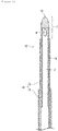
- FIG. 1 is a partially sectional view schematically showing one embodiment of a cautery puncture needle of the present invention.
- Figure 2 is a partially perspective view schematically showing one embodiment of the cautery puncture needle of the present invention.
- the cautery puncture needle 10 of the present embodiment includes a metal hollow pipe 15 having a hollow portion 2 communicating in the longitudinal direction and a distal end electrode portion 7.
- the distal end electrode portion 7 is integrally installed at the distal end of the hollow pipe 15 and is constituted in such a way that when a high-frequency current is passed through the distal end electrode portion 7, Joule heat is thereby generated in a living body.
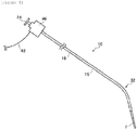
- FIG. 5 is an overall perspective view schematically showing one embodiment of the cautery puncture needle of the present invention.
- a luer connector 46 for example, having a junction cable 42 and a syringe connecting portion 44, is installed on the operation base end side of the cautery puncture needle 10.
- the junction cable 42 is a connection means for electrically connecting a source of generating a high-frequency (radio wave (RF)) current, the hollow pipe 15 and the distal end electrode part 7.
- RF radio wave
- the syringe connecting portion 44 is a luer taper fitting portion to which a syringe is to be connected.
- a liquid medicine can be injected outside from the hole 9 ( Figure 1 ) formed at the side surface of the distal end electrode portion 7. That is, the hole formed at the side surface of the distal end electrode portion functions as an injection hole that injects a liquid medicine, such as a contrast medium, outside.
- the hole 9 that functions as an injection hole that injects a contrast medium is formed nearer to an insertion distal end 12 at the side surface of the distal end electrode portion 7 ( Figure 1 and Figure 2 ). That is, according to the cautery puncture needle 10 of the present embodiment, a contrast medium can be injected from the hole 9 provided at a location nearer to the insertion distal end 12 to be inserted into a living body, and therefore it can easily be confirmed that the distal end electrode portion 7 has reached the opposite side of a membrane tissue, such as the interatrial septum.
- FIG. 3 is a partially perspective view schematically showing another embodiment of the cautery puncture needle of the present invention.
- the cautery puncture needle 20 shown in Figure 3 includes a metal hollow pipe 25 and a distal end electrode portion 17.
- a hole 19 whose opening has a perfectly circular shape, the hole 19 communicating with a hollow portion in the hollow pipe 25, is formed at the side surface of the distal end electrode portion 17.
- the opening of the hole 9 preferably has an oval shape or an elliptical shape extending in the longitudinal direction of the hollow pipe 15.
- Figure 6 is a partially sectional view showing one example of a state of injecting a liquid from the hole.
- Figure 7 is a partially sectional view showing another example of the state of injecting a liquid from the hole.
- the opening of the hole 9 of the cautery puncture needle 10 shown in Figure 6 has an oval shape extending in the longitudinal direction of the hollow pipe ( Figure 1 and Figure 2 ).
- the opening of the hole 19 of the cautery puncture needle 20 shown in Figure 7 has a perfectly circular shape ( Figure 3 ).
- Figure 4 is a partial side view schematically showing one embodiment of the cautery puncture needle of the present invention.
- the ratio of the major axis diameter L to the minor axis diameter S (L/S ratio) of the hole 9 is preferably 1.06 to 6.00, and more preferably 1.19 to 3.67.
- L/S ratio the ratio of the major axis diameter L to the minor axis diameter S (L/S ratio) of the hole 9 is preferably 1.06 to 6.00, and more preferably 1.19 to 3.67.
- the insertion distal end of the distal end electrode portion 7 of the cautery puncture needle 10 preferably has a semi-ellipsoidal shape (artillery shell shape or semi-rugby-ball shape).
- the insertion distal end has a semi-ellipsoidal shape that the outer diameter of the insertion distal end gradually reduces toward the insertion distal end 12, the insertion distal end 12 can be allowed to abut on a narrow location in a membrane tissue, such as the interatrial septum, more surely, and the contact area with the narrow location on which the insertion distal end 12 is allowed to abut can be made smaller.
- the distal end electrode portion is formed with a metal because a high-frequency current is passed through it.
- the metal which forms the distal end electrode portion is not particularly limited as long as a high-frequency current can be passed through it, but is preferably a metal which can be photographed with high contrast by X-ray illumination so that a position in an operation part can easily be confirmed.
- Specific examples of the metal include platinum (Pt), iridium (Ir), and alloy of platinum and iridium (Pt-Ir alloy), and alloy of these metals and stainless steel (Pt-Ir-SUS alloy).
- the hollow pipe 15 can be constituted by a distal end pipe 3 where the distal end electrode portion 7 is installed and a base end pipe 5 which is connected to the base end side of this distal end pipe 3 and has a slightly larger diameter than that of the distal end pipe ( Figure 1 ).
- a distal end pipe 3 where the distal end electrode portion 7 is installed
- a base end pipe 5 which is connected to the base end side of this distal end pipe 3 and has a slightly larger diameter than that of the distal end pipe ( Figure 1 ).
- the hollow pipe (distal end pipe, base end pipe) is formed with a metal having satisfactory flexibility.
- the metal include stainless steel, such as SUS302, SUS304V, and SUS316L, and various alloys, such as Nitinol, and Co-Cr.
- stainless steel such as SUS304V, is preferable.
- a covering layer 16 is formed on the surface of the hollow pipe 15 ( Figure 1 and Figure 2 ).
- the covering layer 16 By forming the covering layer 16, unintended high-frequency wave (radio wave) cauterization to a blood vessel, an internal organ, or the like can be prevented, and sliding resistance of the cautery puncture needle 10 in a living body can be reduced, so that the operability can be improved.
- a hydrophobic resin material is preferable.
- a fluorine-based resin such as PTFE, ETFE, or PFA, is preferable because the sliding resistance of the cautery puncture needle can be reduced more effectively by forming the covering layer with such a fluorine-based resin.
- each part of the distal end electrode portion 7 is preferably as follows ( Figure 4 ). That is, the total length A of the distal end electrode portion 7 (length from insertion distal end 12 to covering layer 16) is preferably 1.16 to 2.50 mm. The length B from the insertion distal end 12 to the distal end of the opening of the hole 9 is preferably 0.50 to 1.10 mm. The length C from the base end of the opening of the hole 9 to the covering layer 16 is preferably 0.30 to 0.80 mm.
- the outer diameter D of the distal end electrode portion 7 is preferably 0.4 to 0.9 mm, and more preferably 0.5 to 0.8 mm ( Figure 4 ).
- injecting a contrast medium is not preferable in some cases for confirming that the distal end electrode portion including the insertion distal end of the cautery puncture needle has reached the opposite side (left atrium) of the interatrial septum.
- the outer diameter D of the distal end electrode portion 7 is in the above-described range, fluctuations in the right atrial pressure and in the left atrial pressure can be measured, so that whether the interatrial septum can be punctured or not can easily be decided.
- the outer diameter D of the distal end electrode portion 7 is less than 0.4 mm, the decision is difficult even though the interatrial septum is punctured because fluctuations in the right atrial pressure and in the left atrial pressure are slight.
- the outer diameter D of the distal end electrode portion 7 exceeds 0.9 mm, there is a tendency that the operability is lowered, and burdens on a living body are large.
- Figures 8A to 8D are partially sectional views describing a procedure of preparing the distal end electrode portion.
- the distal end pipe 3 made of a metal, such as stainless steel, and having the hollow portion 2, and a columnar material 24 for an electrode are first prepared, and the material 24 for an electrode is inserted and fitted into one of the opening ends of the distal end pipe 3.
- the material 24 for an electrode is, for example, a member made of a metal, such as a Pt-Ir alloy.
- the fitted material 24 for an electrode and the opening end of the distal end pipe 3 are welded together by arc welding, such as plasma welding or Tig welding, to form a welded end portion 26 as shown in Figure 8B .
- the welded end portion 26 which is formed is an alloy of the metal constituting the distal end pipe 3 and the metal constituting the material 24 for an electrode ( Figure 8A ).
- the welded end portion 26 which is formed by the above-described welding is joined to the distal end pipe 3 (hollow pipe 15) substantially in a seamless manner.
- the distal end electrode portion 7 having a desired shape, such as a semi-ellipsoidal shape as shown in Figure 8C , can be formed by polishing the welded end portion 26 ( Figure 8B ) which has been formed. Subsequently, by opening the hole 9 communicating with the hollow portion 2 at the side surface of the distal end electrode portion 7 by laser processing or the like, the distal end electrode portion 7 as shown in Figure 8D can be formed.
- the distal end electrode portion 7 which is formed in this way is formed by joining the hollow pipe 15 and the insertion distal end 12 substantially in a seamless manner, and therefore faults, such as dropping of the insertion distal end 12 during use, are less likely to occur and safety is high.
- the distal end electrode portion 7 is formed by joining the hollow pipe 15 and the insertion distal end 12 substantially in a seamless manner, the high-frequency current which has been passed is not stagnated, so that power loss can be reduced.
- the base end of the distal end pipe having the distal end electrode portion prepared in the manner as described above is inserted into the opening end of the base end pipe having a slightly larger diameter than that of this distal end pipe to join these.
- the hollow pipe having a hollow portion communicating from the insertion distal end to the operation base end side can be formed.
- the distal end pipe and the base end pipe are joined by, for example, laser welding, adhesion with an adhesive, a combination of these, or the like. If necessary, uneven processing is preferably performed on the outer peripheral surfaces of the distal end pipe and the base end pipe in advance because the covering layer which is disposed thereafter can be allowed to closely adhere in such a way as to be hard to deviate.
- an adhesion binder is applied on the outer peripheral surface of the hollow pipe, and the hollow pipe is inserted into a heat-shrinkable tube made of a fluororesin, such as PTFE.
- a heat-shrinkable tube made of a fluororesin, such as PTFE.
- the covering layer can thereby be formed at a predetermined location on the outer peripheral surface of the hollow pipe in such a way as to closely adhere.
- a desired location on the hollow pipe 15 is bent to form a bending portion 32, and the operation part, such as the luer connector 46, is connected to the operation base end of the hollow pipe 15, and the cautery puncture needle 10 of the present embodiment can thereby be obtained.
- the cautery puncture needle of the present invention is useful as, for example, a puncture needle for puncturing the interatrial septum that isolates the right atrium and the left atrium.
Landscapes
- Health & Medical Sciences (AREA)
- Surgery (AREA)
- Engineering & Computer Science (AREA)
- Life Sciences & Earth Sciences (AREA)
- Biomedical Technology (AREA)
- Molecular Biology (AREA)
- Nuclear Medicine, Radiotherapy & Molecular Imaging (AREA)
- Plasma & Fusion (AREA)
- Physics & Mathematics (AREA)
- Heart & Thoracic Surgery (AREA)
- Medical Informatics (AREA)
- Otolaryngology (AREA)
- Animal Behavior & Ethology (AREA)
- General Health & Medical Sciences (AREA)
- Public Health (AREA)
- Veterinary Medicine (AREA)
- Surgical Instruments (AREA)
- Media Introduction/Drainage Providing Device (AREA)
Abstract
Description
- The present invention relates to a medical cautery puncture needle to be used for cauterizing and puncturing a treatment part with a high-frequency wave (radio wave).
- A catheter (puncture needle) having a sharp needle disposed at a distal end of the catheter is used as a medical treatment tool for puncturing a targeted treatment part in a living body. In recent years, a cautery puncture needle having an electrode that generates a high-frequency current disposed at the distal end of the catheter has been proposed (see Patent Literature 1). When a puncture needle having a needle disposed at the distal end of the catheter is used, a hole is opened at a targeted treatment part, such as a membrane part, with a needle by adding mechanical pushing force. On the other hand, when a cautery puncture needle is used, an electrode is brought into contact with a targeted treatment part, such as a membrane part, and a high-frequency current is passed through the electrode. Thereby, Joule heat is generated in a living body to cauterize the membrane part, and a hole can thereby be opened in the membrane part.
- When a membrane part is punctured with a puncture needle which a mechanical needle is disposed, adjusting the force to be added is difficult in some cases, and therefore there is a need for sufficient consideration not to damage an unexpected location. On the other hand, when a membrane part is punctured with a cautery puncture needle, a part which is pressed with an electrode at the distal end is moved slightly toward the pressing direction, and a high-frequency current is thereafter passed through the electrode. Thereby, a hole is opened in the pressed part in the membrane part and the electrode at the distal end reaches the opposite side of the membrane part, and the part which has been pressed and moved slightly returns to the original position. Therefore, the use of a cautery puncture needle can reduce the possibility that faults, such as damaging an unexpected location, may occur even in an operation that requires extremely fine operation, such as, for example, puncturing the interatrial septum that isolates the right atrium and the left atrium.
- When a minute membrane tissue, such as the interatrial septum, is punctured, there is a need to confirm that the distal end of a puncture needle has reached the opposite side of the membrane tissue. For example, a puncture needle for cauterization, wherein an injection hole for injecting a contrast medium is formed in a part which is on the base end side of a distal end electrode and is covered with an insulation layer, has been proposed (see Patent Literature 2).
-
- Patent Literature 1:
Japanese Patent Laid-Open No. 2008-237620 - Patent Literature 2: National Publication of International Patent Application No.
2015-518752 - To confirm that the distal end electrode of the puncture needle proposed in
Patent Literature 2 has reached the opposite side of a membrane tissue, there is a need to allow the injection hole to enter into the opposite side of the membrane tissue surely. However, allowing the injection hole to enter into the opposite side of the membrane tissue means that the distal end electrode enters into the opposite side of the membrane tissue more than necessary, and therefore a possibility that faults, such as damaging an unexpected location, occur increases. Moreover, when the distal end electrode is allowed to enter into the opposite side of the membrane tissue more than necessary, burdens on a living body are large. - The present invention has been completed in view of such circumstances, and an object of the present invention is to provide a cautery puncture needle with which faults, such as damaging a peripheral tissue in a living body, are less likely to occur, puncturing a targeted narrow location in a membrane tissue, such as the interatrial septum, can easily be performed, and it can easily be confirmed that the distal end of the cautery puncture needle has reached the opposite side of the membrane tissue.
- The first aspect of the present invention is a cautery puncture needle provided with: a metal hollow pipe having a hollow portion communicating in a longitudinal direction; and a distal end electrode portion through which a high-frequency current is to be passed, the distal end electrode portion integrally installed at a distal end of the hollow pipe, wherein a hole communicating with the hollow portion is formed at a side surface of the distal end electrode portion.
- The second aspect of the present invention is the cautery puncture needle according to the first aspect, wherein an insertion distal end of the distal end electrode portion has a semi-ellipsoidal shape.
- The third aspect of the present invention is the cautery puncture needle according to the second aspect, wherein the distal end electrode portion has an outer diameter of 0.4 to 0.9 mm.
- The fourth aspect of the present invention is the cautery puncture needle according to any one of the first to the third aspects, wherein an opening of the hole has an oval shape or an elliptical shape extending in a longitudinal direction.
- According to the above-described aspects of the present invention, a cautery puncture needle with which faults, such as damaging a peripheral tissue in a living body, are less likely to occur, puncturing a targeted narrow location in a membrane tissue, such as the interatrial septum, can easily be performed, and it can easily be confirmed that the distal end of the cautery puncture needle has reached the opposite side of the membrane tissue can be provided.
-
- [
Figure 1] Figure 1 is a partially sectional view schematically showing one embodiment of a cautery puncture needle of the present invention. - [
Figure 2] Figure 2 is a partially perspective view schematically showing one embodiment of a cautery puncture needle of the present invention. - [
Figure 3] Figure 3 is a partially perspective view schematically showing another embodiment of a cautery puncture needle of the present invention. - [
Figure 4] Figure 4 is a partial side view schematically showing one embodiment of a cautery puncture needle of the present invention. - [
Figure 5] Figure 5 is an overall perspective view schematically showing one embodiment of a cautery puncture needle of the present invention. - [
Figure 6] Figure 6 is a partially sectional view showing one example of a state of injecting a liquid from a hole. - [
Figure 7] Figure 7 is a partially sectional view showing another example of a state of injecting a liquid from a hole. - [
Figure 8A] Figure 8A is a partially sectional view describing a procedure of preparing a distal end electrode portion. - [
Figure 8B] Figure 8B is a partially sectional view describing a procedure of preparing a distal end electrode portion. - [
Figure 8C] Figure 8C is a partially sectional view describing a procedure of preparing a distal end electrode portion. - [
Figure 8D] Figure 8D is a partially sectional view describing a procedure of preparing a distal end electrode portion. - Hereinafter, embodiments of the present invention will be described, but the present invention is not limited to the following embodiments.
Figure 1 is a partially sectional view schematically showing one embodiment of a cautery puncture needle of the present invention.Figure 2 is a partially perspective view schematically showing one embodiment of the cautery puncture needle of the present invention. As shown inFigure 1 andFigure 2 , thecautery puncture needle 10 of the present embodiment includes a metalhollow pipe 15 having ahollow portion 2 communicating in the longitudinal direction and a distalend electrode portion 7. The distalend electrode portion 7 is integrally installed at the distal end of thehollow pipe 15 and is constituted in such a way that when a high-frequency current is passed through the distalend electrode portion 7, Joule heat is thereby generated in a living body. In addition, ahole 9 communicating with thehollow portion 2 in thehollow pipe 15 is formed at the side surface of the distalend electrode portion 7. Thehollow portion 2 communicating with thehole 9 communicates to the operation base end side of thecautery puncture needle 10 in the longitudinal direction of thehollow pipe 15.Figure 5 is an overall perspective view schematically showing one embodiment of the cautery puncture needle of the present invention. As shown inFigure 5 , aluer connector 46, for example, having ajunction cable 42 and asyringe connecting portion 44, is installed on the operation base end side of thecautery puncture needle 10. Thejunction cable 42 is a connection means for electrically connecting a source of generating a high-frequency (radio wave (RF)) current, thehollow pipe 15 and the distalend electrode part 7. Thesyringe connecting portion 44 is a luer taper fitting portion to which a syringe is to be connected. When a syringe filled with a contrast medium is connected to thesyringe connecting portion 44 to inject the contrast medium into the hollow portion, a liquid medicine can be injected outside from the hole 9 (Figure 1 ) formed at the side surface of the distalend electrode portion 7. That is, the hole formed at the side surface of the distal end electrode portion functions as an injection hole that injects a liquid medicine, such as a contrast medium, outside. - In the
cautery puncture needle 10 of the present embodiment, thehole 9 that functions as an injection hole that injects a contrast medium is formed nearer to an insertiondistal end 12 at the side surface of the distal end electrode portion 7 (Figure 1 andFigure 2 ). That is, according to thecautery puncture needle 10 of the present embodiment, a contrast medium can be injected from thehole 9 provided at a location nearer to the insertiondistal end 12 to be inserted into a living body, and therefore it can easily be confirmed that the distalend electrode portion 7 has reached the opposite side of a membrane tissue, such as the interatrial septum. - The opening of the
hole 9 formed at the side surface of the distalend electrode portion 7 of thecautery puncture needle 10 shown inFigure 1 andFigure 2 has an oval shape extending in the longitudinal direction of thehollow pipe 15.Figure 3 is a partially perspective view schematically showing another embodiment of the cautery puncture needle of the present invention. Thecautery puncture needle 20 shown inFigure 3 includes a metalhollow pipe 25 and a distal end electrode portion 17. Ahole 19 whose opening has a perfectly circular shape, thehole 19 communicating with a hollow portion in thehollow pipe 25, is formed at the side surface of the distal end electrode portion 17. As shown inFigure 1 andFigure 2 , the opening of thehole 9 preferably has an oval shape or an elliptical shape extending in the longitudinal direction of thehollow pipe 15. -
Figure 6 is a partially sectional view showing one example of a state of injecting a liquid from the hole.Figure 7 is a partially sectional view showing another example of the state of injecting a liquid from the hole. The opening of thehole 9 of thecautery puncture needle 10 shown inFigure 6 has an oval shape extending in the longitudinal direction of the hollow pipe (Figure 1 andFigure 2 ). On the other hand, the opening of thehole 19 of thecautery puncture needle 20 shown inFigure 7 has a perfectly circular shape (Figure 3 ). As shown inFigure 6 andFigure 7 , the cautery puncture needle 10 (Figure 6 ) in which the opening of thehole 9 has an oval shape or an elliptical shape can inject acontrast medium 14 which is a liquid more forwarder in the insertion direction as compared to the cautery puncture needle 20 (Figure 7 ) in which thehole 19 has a perfectly circular shape. That is, when the opening of the hole is set in such a way as to have an oval shape or an elliptical shape, a contrast medium can be injected forwarder. Accordingly, even though the injection amount of a contrast medium is made smaller, an image can be photographed clearly by X-ray illumination. Thereby, it can be confirmed still more easily that the insertion distal end has reached the opposite side of a membrane tissue. In addition, the injection amount of a contrast medium can be reduced, and therefore burdens on a living body can also be reduced more. -
Figure 4 is a partial side view schematically showing one embodiment of the cautery puncture needle of the present invention. When the opening of thehole 9 has an oval shape or an elliptical shape, the ratio of the major axis diameter L to the minor axis diameter S (L/S ratio) of thehole 9 is preferably 1.06 to 6.00, and more preferably 1.19 to 3.67. By setting the L/S ratio to the above-described range, a contrast medium can be injected from thehole 9 forwarder in the insertion direction. The number of holes which are formed at the distal end electrode portion is not particularly limited, and is preferably set to 1 to 4, and more preferably 2 or 3. By setting the number of holes which are formed at the distal end electrode portion to 2 or 3, the strength of the distal end electrode portion can be retained more suitably. - As shown in
Figure 1 andFigure 2 , the insertion distal end of the distalend electrode portion 7 of thecautery puncture needle 10 preferably has a semi-ellipsoidal shape (artillery shell shape or semi-rugby-ball shape). When the insertion distal end has a semi-ellipsoidal shape that the outer diameter of the insertion distal end gradually reduces toward the insertiondistal end 12, the insertiondistal end 12 can be allowed to abut on a narrow location in a membrane tissue, such as the interatrial septum, more surely, and the contact area with the narrow location on which the insertiondistal end 12 is allowed to abut can be made smaller. When the interatrial septum is supposed to be punctured, positional deviation of the insertiondistal end 12 is liable to occur because the heart is in a state of beating, but when the insertion distal end has a semi-ellipsoidal shape, the pressing force of the insertiondistal end 12 to the interatrial septum can be enhanced. Thereby, the positional deviation of the insertiondistal end 12 is suppressed effectively, so that Joule heat can be concentrated on a desired narrow location in a membrane tissue, enabling opening a hole more surely. - The distal end electrode portion is formed with a metal because a high-frequency current is passed through it. The metal which forms the distal end electrode portion is not particularly limited as long as a high-frequency current can be passed through it, but is preferably a metal which can be photographed with high contrast by X-ray illumination so that a position in an operation part can easily be confirmed. Specific examples of the metal include platinum (Pt), iridium (Ir), and alloy of platinum and iridium (Pt-Ir alloy), and alloy of these metals and stainless steel (Pt-Ir-SUS alloy).
- The
hollow pipe 15 can be constituted by adistal end pipe 3 where the distalend electrode portion 7 is installed and abase end pipe 5 which is connected to the base end side of thisdistal end pipe 3 and has a slightly larger diameter than that of the distal end pipe (Figure 1 ). By constituting the insertion distal end side of thehollow pipe 15 by thedistal end pipe 3 having a smaller diameter, a small hole that is a necessity minimum can be opened. By constituting the operation base end side of thehollow pipe 15 by thebase end pipe 5 having a larger diameter, the movement at the operation part can be transmitted to the distal end more accurately. - The hollow pipe (distal end pipe, base end pipe) is formed with a metal having satisfactory flexibility. Examples of the metal include stainless steel, such as SUS302, SUS304V, and SUS316L, and various alloys, such as Nitinol, and Co-Cr. Among others, stainless steel, such as SUS304V, is preferable.
- A covering
layer 16 is formed on the surface of the hollow pipe 15 (Figure 1 andFigure 2 ). By forming thecovering layer 16, unintended high-frequency wave (radio wave) cauterization to a blood vessel, an internal organ, or the like can be prevented, and sliding resistance of thecautery puncture needle 10 in a living body can be reduced, so that the operability can be improved. As the material for forming thecovering layer 16, a hydrophobic resin material is preferable. Among others, a fluorine-based resin, such as PTFE, ETFE, or PFA, is preferable because the sliding resistance of the cautery puncture needle can be reduced more effectively by forming the covering layer with such a fluorine-based resin. - The size of each part of the distal
end electrode portion 7 is preferably as follows (Figure 4 ). That is, the total length A of the distal end electrode portion 7 (length from insertiondistal end 12 to covering layer 16) is preferably 1.16 to 2.50 mm. The length B from the insertiondistal end 12 to the distal end of the opening of thehole 9 is preferably 0.50 to 1.10 mm. The length C from the base end of the opening of thehole 9 to thecovering layer 16 is preferably 0.30 to 0.80 mm. - The outer diameter D of the distal
end electrode portion 7 is preferably 0.4 to 0.9 mm, and more preferably 0.5 to 0.8 mm (Figure 4 ). When the interatrial septum is supposed to be punctured, injecting a contrast medium is not preferable in some cases for confirming that the distal end electrode portion including the insertion distal end of the cautery puncture needle has reached the opposite side (left atrium) of the interatrial septum. In such a case, when the outer diameter D of the distalend electrode portion 7 is in the above-described range, fluctuations in the right atrial pressure and in the left atrial pressure can be measured, so that whether the interatrial septum can be punctured or not can easily be decided. When the outer diameter D of the distalend electrode portion 7 is less than 0.4 mm, the decision is difficult even though the interatrial septum is punctured because fluctuations in the right atrial pressure and in the left atrial pressure are slight. On the other hand, when the outer diameter D of the distalend electrode portion 7 exceeds 0.9 mm, there is a tendency that the operability is lowered, and burdens on a living body are large. - Next, a method for producing the cautery puncture needle of the present invention will be described.
Figures 8A to 8D are partially sectional views describing a procedure of preparing the distal end electrode portion. To prepare the distal end electrode portion, as shown inFigure 8A , thedistal end pipe 3 made of a metal, such as stainless steel, and having thehollow portion 2, and acolumnar material 24 for an electrode are first prepared, and thematerial 24 for an electrode is inserted and fitted into one of the opening ends of thedistal end pipe 3. Thematerial 24 for an electrode is, for example, a member made of a metal, such as a Pt-Ir alloy. Subsequently, the fittedmaterial 24 for an electrode and the opening end of thedistal end pipe 3 are welded together by arc welding, such as plasma welding or Tig welding, to form a weldedend portion 26 as shown inFigure 8B . The weldedend portion 26 which is formed is an alloy of the metal constituting thedistal end pipe 3 and the metal constituting thematerial 24 for an electrode (Figure 8A ). The weldedend portion 26 which is formed by the above-described welding is joined to the distal end pipe 3 (hollow pipe 15) substantially in a seamless manner. - The distal
end electrode portion 7 having a desired shape, such as a semi-ellipsoidal shape as shown inFigure 8C , can be formed by polishing the welded end portion 26 (Figure 8B ) which has been formed. Subsequently, by opening thehole 9 communicating with thehollow portion 2 at the side surface of the distalend electrode portion 7 by laser processing or the like, the distalend electrode portion 7 as shown inFigure 8D can be formed. The distalend electrode portion 7 which is formed in this way is formed by joining thehollow pipe 15 and the insertiondistal end 12 substantially in a seamless manner, and therefore faults, such as dropping of the insertiondistal end 12 during use, are less likely to occur and safety is high. In addition, when the distalend electrode portion 7 is formed by joining thehollow pipe 15 and the insertiondistal end 12 substantially in a seamless manner, the high-frequency current which has been passed is not stagnated, so that power loss can be reduced. - The base end of the distal end pipe having the distal end electrode portion prepared in the manner as described above is inserted into the opening end of the base end pipe having a slightly larger diameter than that of this distal end pipe to join these. Thereby, the hollow pipe having a hollow portion communicating from the insertion distal end to the operation base end side can be formed. The distal end pipe and the base end pipe are joined by, for example, laser welding, adhesion with an adhesive, a combination of these, or the like. If necessary, uneven processing is preferably performed on the outer peripheral surfaces of the distal end pipe and the base end pipe in advance because the covering layer which is disposed thereafter can be allowed to closely adhere in such a way as to be hard to deviate.
- Subsequently, an adhesion binder is applied on the outer peripheral surface of the hollow pipe, and the hollow pipe is inserted into a heat-shrinkable tube made of a fluororesin, such as PTFE. When the heat-shrinkable tube is shrunken by moderate heating, the covering layer can thereby be formed at a predetermined location on the outer peripheral surface of the hollow pipe in such a way as to closely adhere. Thereafter, as shown in
Figure 5 , a desired location on thehollow pipe 15 is bent to form a bendingportion 32, and the operation part, such as theluer connector 46, is connected to the operation base end of thehollow pipe 15, and thecautery puncture needle 10 of the present embodiment can thereby be obtained. - The cautery puncture needle of the present invention is useful as, for example, a puncture needle for puncturing the interatrial septum that isolates the right atrium and the left atrium.
-
- 2: Hollow portion
- 3: Distal end pipe
- 5: Base end pipe
- 7, 17: Distal end electrode portion
- 9, 19: Hole
- 10, 20: Cautery puncture needle
- 12: Insertion distal end
- 14: Contrast medium
- 15, 25: Hollow portion
- 16: Covering layer
- 24: Material for electrode
- 26: Welded end part
- 32: Bending portion
- 42: Junction cable
- 44: Syringe connecting portion
- 46: Luer connector
Claims (4)
- A cautery puncture needle comprising:a metal hollow pipe having a hollow portion communicating in a longitudinal direction; anda distal end electrode portion through which a high-frequency current is to be passed, the distal end electrode portion integrally installed at a distal end of the hollow pipe, whereina hole communicating with the hollow portion is formed at a side surface of the distal end electrode portion.
- The cautery puncture needle according to claim 1, wherein an insertion distal end of the distal end electrode portion has a semi-ellipsoidal shape.
- The cautery puncture needle according to claim 2, wherein the distal end electrode portion has an outer diameter of 0.4 to 0.9 mm.
- The cautery puncture needle according to any one of claims 1 to 3, wherein an opening of the hole has an oval shape or an elliptical shape extending in a longitudinal direction.
Applications Claiming Priority (2)
| Application Number | Priority Date | Filing Date | Title |
|---|---|---|---|
| JP2018183150A JP7165009B2 (en) | 2018-09-28 | 2018-09-28 | cautery puncture needle |
| PCT/JP2019/027533 WO2020066226A1 (en) | 2018-09-28 | 2019-07-11 | Cautery puncture needle |
Publications (2)
| Publication Number | Publication Date |
|---|---|
| EP3858273A1 true EP3858273A1 (en) | 2021-08-04 |
| EP3858273A4 EP3858273A4 (en) | 2022-06-15 |
Family
ID=69952558
Family Applications (1)
| Application Number | Title | Priority Date | Filing Date |
|---|---|---|---|
| EP19864134.2A Pending EP3858273A4 (en) | 2018-09-28 | 2019-07-11 | PUNCTURE NEEDLE FOR CAUTERATION |
Country Status (5)
| Country | Link |
|---|---|
| US (1) | US20220031383A1 (en) |
| EP (1) | EP3858273A4 (en) |
| JP (1) | JP7165009B2 (en) |
| CN (2) | CN120000321A (en) |
| WO (1) | WO2020066226A1 (en) |
Families Citing this family (6)
| Publication number | Priority date | Publication date | Assignee | Title |
|---|---|---|---|---|
| JP7510885B2 (en) * | 2021-01-05 | 2024-07-04 | 株式会社カネカ | Septal puncture device |
| CN116916994B (en) * | 2021-02-22 | 2026-04-17 | 株式会社钟化 | Puncture device |
| CN113952522A (en) * | 2021-10-27 | 2022-01-21 | 西安交通大学医学院第二附属医院 | Accurate puncture drainage device of brain abscess |
| KR102458997B1 (en) * | 2022-02-22 | 2022-10-25 | 문기철 | Cardiac septal puncture needle with conical tipe |
| JP7842641B2 (en) * | 2022-05-31 | 2026-04-08 | 株式会社カネカ | Puncture device |
| JP2024136977A (en) | 2023-03-24 | 2024-10-04 | 日本ライフライン株式会社 | Balloon-type ablation device |
Family Cites Families (12)
| Publication number | Priority date | Publication date | Assignee | Title |
|---|---|---|---|---|
| US5431649A (en) * | 1993-08-27 | 1995-07-11 | Medtronic, Inc. | Method and apparatus for R-F ablation |
| US7229413B2 (en) * | 1996-11-06 | 2007-06-12 | Angiotech Biocoatings Corp. | Echogenic coatings with overcoat |
| US10493259B2 (en) * | 2003-01-21 | 2019-12-03 | Baylis Medical Company Inc. | Medical apparatus for fluid communication |
| JP4683434B2 (en) | 2007-03-27 | 2011-05-18 | 日本ライフライン株式会社 | Ablation needle |
| WO2008139829A1 (en) * | 2007-05-09 | 2008-11-20 | Japan Science And Technology Agency | Guide wire and stent |
| US8603049B2 (en) * | 2008-12-15 | 2013-12-10 | Kimberly-Clark Worldwide, Inc. | Atraumatic suction catheter |
| JP6416084B2 (en) * | 2012-05-31 | 2018-10-31 | ベイリス メディカル カンパニー インコーポレイテッドBaylis Medical Company Inc. | Medical equipment |
| BR112016022204B1 (en) * | 2014-03-24 | 2022-05-24 | Baylis Medical Company Inc | MEDICAL DEVICE FOR FLUID COMMUNICATION |
| WO2015153815A1 (en) * | 2014-04-01 | 2015-10-08 | Gregory Brucker | Temperature-responsive irrigated ablation electrode with reduced coolant flow and related methods for making and using |
| CN205083453U (en) * | 2015-11-02 | 2016-03-16 | 嘉兴职业技术学院 | Comprehensive weaving electrode |
| US10675085B2 (en) * | 2015-11-23 | 2020-06-09 | Boston Scientific Scimed, Inc. | Devices and methods for enhanced denervation procedures |
| CN108272503B (en) * | 2018-03-07 | 2024-04-19 | 南微医学科技股份有限公司 | Double-channel liquid injection bipolar high-frequency electric knife |
-
2018
- 2018-09-28 JP JP2018183150A patent/JP7165009B2/en active Active
-
2019
- 2019-07-11 WO PCT/JP2019/027533 patent/WO2020066226A1/en not_active Ceased
- 2019-07-11 CN CN202510311624.3A patent/CN120000321A/en active Pending
- 2019-07-11 CN CN201980058888.5A patent/CN112672708A/en active Pending
- 2019-07-11 US US17/278,906 patent/US20220031383A1/en not_active Abandoned
- 2019-07-11 EP EP19864134.2A patent/EP3858273A4/en active Pending
Also Published As
| Publication number | Publication date |
|---|---|
| WO2020066226A1 (en) | 2020-04-02 |
| JP2020049038A (en) | 2020-04-02 |
| US20220031383A1 (en) | 2022-02-03 |
| JP7165009B2 (en) | 2022-11-02 |
| CN112672708A (en) | 2021-04-16 |
| CN120000321A (en) | 2025-05-16 |
| EP3858273A4 (en) | 2022-06-15 |
Similar Documents
| Publication | Publication Date | Title |
|---|---|---|
| US20220031383A1 (en) | Cautery puncture needle | |
| US11833316B2 (en) | Guide wire, medical device, and treatment method | |
| CN109803597B (en) | Medical device and treatment method | |
| KR20160138113A (en) | Medical apparatus for fluid communication | |
| JP7309688B2 (en) | medical device | |
| JP7791834B2 (en) | Lancing Device | |
| US12533487B2 (en) | Medical device for puncturing | |
| WO2018163899A1 (en) | Puncture device, medical device, and treatment method | |
| JP6529770B2 (en) | Electrode catheter, manufacturing method of electrode catheter | |
| US20230255683A1 (en) | Elongated medical needle assembly | |
| US20240293172A1 (en) | Cautery puncture needle | |
| CN217938363U (en) | Needle type ablation catheter | |
| JP7510885B2 (en) | Septal puncture device | |
| JP7557391B2 (en) | Lancing Device | |
| US20240277399A1 (en) | Rf wire connection in dilator | |
| EP4295886B1 (en) | Puncturing device | |
| US20250000570A1 (en) | Radiofrequency Cannula for Thermal Ablation | |
| JP6944996B2 (en) | High frequency treatment tool for endoscopes | |
| JP2024139432A (en) | Method for manufacturing electrode catheter | |
| WO2024218071A1 (en) | Coiled wire electrode |
Legal Events
| Date | Code | Title | Description |
|---|---|---|---|
| STAA | Information on the status of an ep patent application or granted ep patent |
Free format text: STATUS: THE INTERNATIONAL PUBLICATION HAS BEEN MADE |
|
| PUAI | Public reference made under article 153(3) epc to a published international application that has entered the european phase |
Free format text: ORIGINAL CODE: 0009012 |
|
| STAA | Information on the status of an ep patent application or granted ep patent |
Free format text: STATUS: REQUEST FOR EXAMINATION WAS MADE |
|
| 17P | Request for examination filed |
Effective date: 20210315 |
|
| AK | Designated contracting states |
Kind code of ref document: A1 Designated state(s): AL AT BE BG CH CY CZ DE DK EE ES FI FR GB GR HR HU IE IS IT LI LT LU LV MC MK MT NL NO PL PT RO RS SE SI SK SM TR |
|
| DAV | Request for validation of the european patent (deleted) | ||
| DAX | Request for extension of the european patent (deleted) | ||
| A4 | Supplementary search report drawn up and despatched |
Effective date: 20220517 |
|
| RIC1 | Information provided on ipc code assigned before grant |
Ipc: A61B 18/00 20060101ALN20220511BHEP Ipc: A61B 17/34 20060101ALN20220511BHEP Ipc: A61B 18/14 20060101AFI20220511BHEP |
|
| STAA | Information on the status of an ep patent application or granted ep patent |
Free format text: STATUS: EXAMINATION IS IN PROGRESS |
|
| 17Q | First examination report despatched |
Effective date: 20240321 |