EP3858174A1 - Aerosol delivery system - Google Patents
Aerosol delivery system Download PDFInfo
- Publication number
- EP3858174A1 EP3858174A1 EP20154504.3A EP20154504A EP3858174A1 EP 3858174 A1 EP3858174 A1 EP 3858174A1 EP 20154504 A EP20154504 A EP 20154504A EP 3858174 A1 EP3858174 A1 EP 3858174A1
- Authority
- EP
- European Patent Office
- Prior art keywords
- heat source
- air
- aerosol delivery
- delivery system
- passage
- Prior art date
- Legal status (The legal status is an assumption and is not a legal conclusion. Google has not performed a legal analysis and makes no representation as to the accuracy of the status listed.)
- Ceased
Links
Images


Classifications
-
- A—HUMAN NECESSITIES
- A24—TOBACCO; CIGARS; CIGARETTES; SIMULATED SMOKING DEVICES; SMOKERS' REQUISITES
- A24F—SMOKERS' REQUISITES; MATCH BOXES; SIMULATED SMOKING DEVICES
- A24F42/00—Simulated smoking devices other than electrically operated; Component parts thereof; Manufacture or testing thereof
- A24F42/10—Devices with chemical heating means
Definitions
- the present invention relates to an aerosol delivery system.
- a system is of particular, but not necessary exclusive interest as a smoking substitute system. It is a preferred feature of operation of the system that it is able to deliver an active ingredient (such as nicotine) to a user for inhalation without producing a visible vapour cloud.
- an active ingredient such as nicotine
- the smoking of tobacco is generally considered to expose a smoker to potentially harmful substances. It is thought that a significant amount of the potentially harmful substances are generated through the burning and/or combustion of the tobacco and the constituents of the burnt tobacco in the tobacco smoke itself.
- Such smoking substitute systems can form part of nicotine replacement therapies aimed at people who wish to stop smoking and overcome a dependence on nicotine.
- Known smoking substitute systems include electronic systems that permit a user to simulate the act of smoking by producing an aerosol (also referred to as a "vapour") that is drawn into the lungs through the mouth (inhaled) and then exhaled.
- the inhaled aerosol typically bears nicotine and/or a flavourant without, or with fewer of, the health risks associated with conventional smoking.
- smoking substitute systems are intended to provide a substitute for the rituals of smoking, whilst providing the user with a similar, or improved, experience and satisfaction to those experienced with conventional smoking and with combustible tobacco products.
- smoking substitute systems have grown rapidly in the past few years. Although originally marketed as an aid to assist habitual smokers wishing to quit tobacco smoking, consumers are increasingly viewing smoking substitute systems as desirable lifestyle accessories. There are a number of different categories of smoking substitute systems, each utilising a different smoking substitute approach. Some smoking substitute systems are designed to resemble a conventional cigarette and are cylindrical in form with a mouthpiece at one end. Other smoking substitute devices do not generally resemble a cigarette (for example, the smoking substitute device may have a generally box-like form, in whole or in part).
- a vaporisable liquid, or an aerosol former sometimes typically referred to herein as “e-liquid”
- e-liquid is heated by a heating device (sometimes referred to herein as an electronic cigarette or “e-cigarette” device) to produce an aerosol vapour which is inhaled by a user.
- the e-liquid typically includes a base liquid, nicotine and may include a flavourant.
- the resulting vapour therefore also typically contains nicotine and/or a flavourant.
- the base liquid may include propylene glycol and/or vegetable glycerine.
- a typical e-cigarette device includes a mouthpiece, a power source (typically a battery), a tank for containing e-liquid and a heating device.
- a power source typically a battery
- a tank for containing e-liquid In use, electrical energy is supplied from the power source to the heating device, which heats the e-liquid to produce an aerosol (or "vapour") which is inhaled by a user through the mouthpiece.
- E-cigarettes can be configured in a variety of ways.
- there are "closed system" vaping smoking substitute systems which typically have a sealed tank and heating element. The tank is prefilled with e-liquid and is not intended to be refilled by an end user.
- One subset of closed system vaping smoking substitute systems include a main body which includes the power source, wherein the main body is configured to be physically and electrically couplable to a consumable including the tank and the heating element. In this way, when the tank of a consumable has been emptied of e-liquid, that consumable is removed from the main body and disposed of. The main body can then be reused by connecting it to a new, replacement, consumable.
- Another subset of closed system vaping smoking substitute systems are completely disposable, and intended for one-use only.
- vaping smoking substitute systems which typically have a tank that is configured to be refilled by a user. In this way the entire device can be used multiple times.
- An example vaping smoking substitute system is the mybluTM e-cigarette.
- the mybluTM e-cigarette is a closed system which includes a main body and a consumable.
- the main body and consumable are physically and electrically coupled together by pushing the consumable into the main body.
- the main body includes a rechargeable battery.
- the consumable includes a mouthpiece and a sealed tank which contains e-liquid.
- the consumable further includes a heater, which for this device is a heating filament coiled around a portion of a wick. The wick is partially immersed in the e-liquid, and conveys e-liquid from the tank to the heating filament.
- the system is controlled by a microprocessor on board the main body.
- the system includes a sensor for detecting when a user is inhaling through the mouthpiece, the microprocessor then activating the device in response.
- the system When the system is activated, electrical energy is supplied from the power source to the heating device, which heats e-liquid from the tank to produce a vapour which is inhaled by a user through the mouthpiece.
- vaping-type smoking substitute systems is an inhaler apparatus, of which a particular example is the Nicorette® inhalator (trade name). Such systems are often passive in the sense that they do not require a source of heat or other activation energy in order to generate a vapour.
- an inhaler typically includes a mouthpiece and a main body containing a source of nicotine.
- a user may inhale or "puff' on the mouthpiece to draw air over or through the nicotine source.
- the nicotine source may be, for example, an air-permeable substrate impregnated with nicotine. When the supply of nicotine in the nicotine source is depleted, such that the user no longer receives sufficient (or any) nicotine with each puff, the user can replace the nicotine source in order to continue nicotine delivery.
- Smoking substitute systems e.g. e-cigarettes
- e-cigarettes are generally regarded as having fewer of the health risks associated with conventional smoking, not only for the user themselves, but also for those nearby (i.e. those affected by passive smoking).
- the exhaling of a visible vapour cloud by the user may still be regarded in some circumstances as socially unacceptable, in light of the negative views surrounding smoking itself. Therefore, many locations where smoking is not permitted also do not allow smoking substitute systems, instead requiring users to use the same designated smoking areas as smokers themselves. This can reduce the attractiveness of smoking substitute systems, and reduce their uptake as a smoking cessation aid.
- a smoking substitute system that can provide a similar user experience to an e-cigarette, but without producing a visible vapour cloud.
- a smoking substitute system that can allow a user to select whether or not the system produces a vapour cloud by switching between one system operating mode where a vapour cloud is produced and another system operating mode where a vapour cloud is not produced.
- an aerosol delivery system not necessarily limited to a smoking substitute system, for the delivery of an active ingredient to a user by inhalation, providing the beneficial effects referred to above.
- the present invention relates to an aerosol delivery system with a non-electrical heat source, wherein an air passage around or through the heat source follows an extended path.
- an aerosol delivery system comprising an air inlet, an outlet, and an air passage extending from the air inlet to the outlet.
- a part of the air passage is defined by a heat source air passage extending through a heat source operable to heat air in the heat source air passage through an exothermic reaction.
- a reservoir formed from an air-permeable substrate is arranged to allow air in the air passage drawn from the outlet of the air passage to be drawn through the reservoir and on to the outlet, the reservoir being loaded with a source of an active ingredient.
- the heat source air passage has a heat source air inlet and a heat source air outlet, spaced apart on the heat source by a separation distance, wherein, in use, the heat source air passage conveys air along a flow path within the heat source from the heat source air inlet to the heat source air outlet, and wherein the length of the flow path is greater than the separation distance.
- the aerosol delivery system is a smoking substitute system.
- the active ingredient may comprise or consist of nicotine.
- a heat source air passage of this configuration allows improved heating of the air flowing through the heat source air passage, by providing a greater flow path length proximate to the heat source.
- the length of the flow path may be not less than 1.1 times the separation distance, preferably not less than 1.5 times the separation distance, not less than 2 times the separation distance, not less than 5 times the separation distance or not less than 10 times the separation distance.
- a higher ratio of flow path length to separation distance can improve the heat transfer between the heat source and the air in the heat source passage.
- the length of the flow path may be less than 100 times the separation distance, preferably less than 80 times the separation distance, or less than 50 times the separation distance, or less than 20 times the separation distance.
- a lower ratio of flow path length to separation distance can provide a less restrictive flow path, by allowing a larger cross-sectional area configuration for the heat source air passage, reducing the effect of the heat source air passage on the overall resistance to draw for the smoking substitute apparatus.
- the heat source air passage conveys air along a tortuous flow path.
- a torturous flow path may comprise one or more loops or turns or corners or may be, for example, a helical flow path, or a serpentine flow path.
- the aerosol delivery system may comprises a plurality of separate heat source air passages. At least two of the heat source air passages may extend from a common heat source air inlet. At least two of the heat source air passages may extend to a common heat source air outlet.
- the exothermic reaction of the heat source may be a crystallisation of a super-saturated solution.
- the exothermic reaction of the heat source may be initiable by operation of a multistable trigger element or bistable trigger element.
- the bistable trigger element might be a metallic disc which is operable by inversion from a convex configuration to a concave configuration and/or a concave configuration to a convex configuration.
- the metallic disc may be invertable using a lever movable in contact with the metallic disc.
- the exothermic reaction of the heat source may be an oxidation reaction.
- the oxidation reaction may be a reaction between iron powder and oxygen.
- the oxygen may be atmospheric oxygen.
- the exothermic reaction may be initiable by removal of an oxygen impermeable seal from a reaction chamber of the heat source.
- the exothermic reaction of the heat source may be a reaction between two or more substances stored inside the heat source and initiable by contact between the two or more substances.
- the contact between the two or more substances may comprise mixing of the two substances. Such mixing may be by diffusion. Additionally or alternatively, the mixing may be caused or improved by agitation of the heat source, for example by shaking of the heat source or smoking substitute system.
- the heat source may be a replaceable component of the smoking substitute system.
- a kit of parts for an aerosol delivery system comprising a base unit, an aerosol delivery apparatus removably engageable with the base unit, and the heat source.
- the aerosol delivery apparatus is a cartridge configured for engagement with the base unit, the cartridge comprising the reservoir.
- the heat source may be comprised within the base unit.
- the heat source may be comprised within the aerosol delivery apparatus.
- a method of using an aerosol delivery system according to the first aspect comprising the steps of initiating the exothermic reaction, and drawing air through the passage to generate heated air in the heat source air passage and through the reservoir to generate a vapour.
- the aerosol delivery apparatus may be in the form of a consumable.
- the consumable may be configured for engagement with a main body.
- the combination of the consumable and the main body may form an aerosol delivery system such as a closed smoking substitute system.
- the consumable may comprise components of the system that are disposable, and the main body may comprise non-disposable or non-consumable components (e.g. power supply, controller, sensor, etc.) that facilitate the generation and/or delivery of aerosol by the consumable.
- an aerosol precursor e.g. e-liquid
- other nicotine source e.g. nicotine-infused air-permeable substrate
- the aerosol delivery apparatus may be a non-consumable apparatus (e.g. that is in the form of an open aerosol delivery system).
- an aerosol former e.g. e-liquid
- the aerosol precursor may be replenished by re-filling, e.g. a reservoir of the aerosol delivery apparatus, with the aerosol precursor (rather than replacing a consumable component of the apparatus).
- the main body and the consumable may be configured to be physically coupled together.
- the consumable may be at least partially received in a recess of the main body, such that there is an interference fit between the main body and the consumable.
- the main body and the consumable may be physically coupled together by screwing one onto the other, or through a bayonet fitting, or the like.
- the aerosol delivery apparatus may comprise one or more engagement portions for engaging with a main body.
- one end of the aerosol delivery apparatus may be coupled with the main body, whilst an opposing end of the aerosol delivery apparatus may define a mouthpiece of the aerosol delivery system.
- the air-permeable substrate comprises at least one volatile compound that is intended to be vaporised/aerosolised and that may provide the user with a recreational, wellness, nutritional, physiological and/or medicinal effect when inhaled.
- a volatile compound is referred to herein as an "active agent" or "active ingredient”.
- the active ingredient may comprise or consist of nicotine. However, in some embodiments, the active ingredient may not comprise nicotine, and may instead comprise or consist of one or more of a nutritional agent, a pharmaceutical agent or a flavour agent.
- Suitable active agents include the group consisting of: nicotine, cocaine, caffeine (anhydrous or salts thereof), vitamins, minerals, amino acids, plant or herbal concentrated extracts, sugars, opiates and opioids, cathine and cathinone, kavalactones, mysticin, beta-carboline alkaloids, salvinorin A, cannabinoids, phytocannabinoids, one or more flavourants, together with any combinations, functional equivalents to, and/or synthetic alternatives of the foregoing.
- Example flavourants may include menthol, liquorice, chocolate, fruit flavour (including e.g. citrus, cherry etc.), vanilla, spice (e.g. ginger, cinnamon) and tobacco flavour.
- Cannabinoid compounds include phyto-cannabinoids which include:
- the cannabinoid compound is selected from at least one of cannabidiol (CBD) and its derivatives/homologues e.g. cannabiodiol-Cs (CBD-C 5 ), cannabidiol-C 4 (CBD-C 4 ), cannabidiol mono(m)ethyl ether (CBDM-C 5 ), cannabidivarin (CBDV-C 3 ), cannabidiorcol (CBD-C 1 ), cannabidiolic acid (CBDA-C 5 ), cannabidivarinic acid (CBDVA-C 3 ).
- CBD cannabidiol
- CBD-C 5 cannabidiol-C 5
- CBD-C 4 cannabidiol mono(m)ethyl ether
- CBDDV-C 3 cannabidivarin
- CBD-C 1 cannabidiorcol
- CBDDA-C 5 cannabidivarinic acid
- the cannabinoid compound is selected from at least one of tetrahydrocannabinol (THC) and its derivatives/homologues, e.g. ⁇ 9 -tetrahydrocannabinol ( ⁇ 9 -THC-C 5 / cis - ⁇ 9 -THC-C 5 ), ⁇ 8 -tetrahydrocannabinol ( ⁇ 8 -THC-C 5 ), ⁇ 8 -tetrahydrocannabinolic acid A ( ⁇ 8 -THCA-C 5 A), ⁇ 9 -tetrahydrocannabinol-C 4 ( ⁇ 9 -THC-C 4 ), ⁇ 9 -tetrahydrocannabivarin ( ⁇ 9 -THCV-C 3 ), ⁇ 9 -tetrahydrocannabiorcol ( ⁇ 9 -THCO-C 1 ), ⁇ 9 -tetrahydrocannabinolic acid A ( ⁇ 9 -THC) and its
- the total amount of cannabinoid compounds in the substrate may be at least 200 mg; for example, it may be at least 250 mg, at least 300 mg, at least 400 mg, at least 500 mg. In some cases, lower amounts may be preferred.
- the total amount of cannabinoid compounds in the substrate may therefore be at least 10 mg, at least 20 mg, at least 30 mg, at least 40 mg, at least 50 mg, at least 75 mg, at least 100 mg.
- the total amount of cannabinoid compounds may be not more than 200 mg, not more than 175 mg, not more than 150 mg, not more than 125 mg, not more than 100 mg, not more than 75 mg, not more than 50 mg, not more than 40 mg, not more than 30 mg, not more than 20 mg, not more than 10 mg. In some cases, the total amount of the cannabinoid compounds may be not more than 5 mg.
- the total of amount of THC may be limited.
- the total amount of THC in the substrate is not more than 100 mg, not more than 75 mg, not more than 50 mg, not more than 40 mg, not more than 30 mg, not more than 20 mg, not more than 15 mg, not more than 10 mg, not more than 5 mg, not more than 3 mg.
- the amount of THC may be 0.1 to 30 mg, for example 1 to 30 mg, for example 1 to 20 mg, for example 1 to 10 mg, for example 1 to 5 mg, for example 1 to 3 mg.
- the aerosol delivery apparatus may comprise a reservoir configured to store an aerosol precursor.
- the aerosol precursor may be formulated so as to produce a non-visible or substantially non-visible vapour.
- the aerosol precursor may comprise a base liquid.
- the aerosol precursor may additionally comprise nicotine.
- the aerosol precursor may be an e-liquid.
- the aerosol precursor may consist substantially of nicotine or a nicotine compound.
- the aerosol precursor may further comprise a flavourant.
- the aerosol precursor may be substantially flavourless. That is, the aerosol precursor may not contain any deliberately added additional flavourant.
- a flavourant may be provided as a separate flavourant aerosol precursor, such that the aerosol precursor and flavourant aerosol precursor may be separately vaporised to form an aerosol comprising both the aerosol precursor and the flavourant aerosol precursor.
- the reservoir configured to store the aerosol precursor and/or the flavourant aerosol precursor may consist of an air-permeable substrate impregnated with the aerosol precursor and/or the flavourant aerosol precursor.
- the substrate material may be a foamed polymer which will allow for airflow to pass through the substrate at a given pressure drop value, so as to provide a comfortable 'draw' sensation for the user.
- the substrate may be, for example, a sintered polyethylene or a PET foam.
- the substrate may be impregnated with nicotine via immersion in a liquid containing nicotine and a volatile carrier (for example a solution of nicotine in ethanol).
- a volatile carrier for example a solution of nicotine in ethanol.
- the substrate is immersed to evenly soak the substrate. Once removed and left to dry or baked in an oven, the carrier is evaporated and the nicotine is left evenly spread throughout the substrate.
- the aerosol precursor and/or the flavourant aerosol precursor may be formulated to form a vapour when ambient air is drawn through the reservoir.
- the aerosol precursor and/or the flavourant aerosol precursor may be formulated to form a vapour when heated air is drawn through the reservoir.
- the reservoir may comprise a monolithic substrate.
- the reservoir may consist of a plurality of substrates, each arranged to allow air to be drawn therethrough, and each comprising one or both of an aerosol precursor and the flavourant aerosol precursor.
- the aerosol precursor and/or the flavourant aerosol precursor may be provided in spatially coterminous or spatially distinct regions of the reservoir.
- the aerosol precursor reservoir may be in the form of a tank. At least a portion of the tank may be light-transmissive.
- the tank may comprise a window to allow a user to visually assess the quantity of aerosol precursor in the tank.
- a housing of the aerosol delivery apparatus may comprise a corresponding aperture (or slot) or window that may be aligned with a light-transmissive portion (e.g. window) of the tank.
- the reservoir may be referred to as a "clearomizer” if it includes a window, or a "cartomizer” if it does not.
- the aerosol delivery apparatus may comprise one or more passages for fluid (e.g. air) flow therethrough. Where more than one passage is present, one or more of the passages may be distinct, such that there is no intersection between the passages. One or more of the passages may comprise junctions or openings therebetween such that fluid within the passages can mix within the aerosol delivery apparatus.
- fluid e.g. air
- One or more of the passages may comprise one or more valves to control fluid flow.
- the valve may be, for example, a one-way valve to ensure fluid (i.e. air) can only flow through the passage in a desired direction.
- the valve may be operable to open and close the passage such that fluid is enabled to or prevented from flowing through the passage. More than one valve may be linked such that the valves may be operated in combination or in synchronism with each other.
- a valve to open and close a passage may be controlled by mechanical means (i.e. the user moves the valve using a control lever or similar).
- the passages may extend through (at least a portion of) the aerosol delivery apparatus, between openings that may define an inlet and an outlet of a passage.
- Each inlet and outlet may be in fluid communication with only one passage, or a subset of the passages, or all the passages in the aerosol delivery apparatus.
- the outlet or outlets may be at a mouthpiece of the aerosol delivery apparatus.
- a user may draw fluid (e.g. air) into and through a passage by inhaling at the outlet (i.e. using the mouthpiece).
- a passage through the aerosol delivery apparatus may be at least partially defined by a tank forming the aerosol precursor reservoir.
- the tank may substantially (or fully) define the passage, for at least a part of the length of the passage.
- the tank may surround the passage, e.g. in an annular arrangement around the passage.
- One or more of the fluid passages may comprise a heater for heating the fluid (i.e. air) passing through the passage.
- the heater may, for example, be arranged upstream of a reservoir formed from an air permeable substrate such that air warmed by the heater is drawn through the reservoir to enable or increase nicotine or flavourant vapourisation and subsequent entrainment in the air-flow.
- the heater to heat the air may comprise one or more thermally conductive elements to conduct heat from a heater to the air passage or to increase the heat transfer between the heater and the air.
- the heat source is non-electrical.
- the heat to heat the air may be generated by an exothermic reaction.
- An exothermic reaction heat source may comprise a single-use (i.e. consumable) reaction container.
- an exothermic reaction heat source may be rechargeable (e.g. by using a reversible reaction such as a crystallisation process).
- flavourant is used to describe a compound or combination of compounds that provide flavour and/or aroma.
- the flavourant may be configured to interact with a sensory receptor of a user (such as an olfactory or taste receptor).
- the flavourant may include one or more volatile substances.
- the flavourant may be provided in solid or liquid form.
- the flavourant may be natural or synthetic.
- the flavourant may include menthol, liquorice, chocolate, fruit flavour (including e.g. citrus, cherry etc.), vanilla, spice (e.g. ginger, cinnamon) and tobacco flavour.
- the flavourant may be evenly dispersed or may be provided in isolated locations and/or varying concentrations.
- the air-permeable substrate may comprise plant material.
- the plant material may comprise least one plant material selected from the list including Amaranthus dubius, Arctostaphylos uva-ursi (Bearberry), Argemone mexicana, Amica, Artemisia vulgaris, Yellow Tees, Galea zacatechichi, Canavalia maritima (Baybean), Cecropia mexicana (Guamura), Cestrum noctumum, Cynoglossum virginianum (wild comfrey), Cytisus scoparius , Damiana , Entada rheedii , Eschscholzia califomica (California Poppy), Fittonia albivenis, Hippobroma longiflora , Humulus japonica (Japanese Hops), Humulus lupulus (Hops), Lactuca virosa (Lettuce Opium), Laggera alata
- the plant material is tobacco. Any type of tobacco may be used. This includes, but is not limited to, flue-cured tobacco, burley tobacco, Maryland Tobacco, dark-air cured tobacco, oriental tobacco, dark-fired tobacco, perique tobacco and rustica tobacco. This also includes blends of the above mentioned tobaccos.
- any suitable parts of the tobacco plant may be used. This includes leaves, stems, roots, bark, seeds and flowers.
- the tobacco may comprise one or more of leaf tobacco, stem tobacco, tobacco powder, tobacco dust, tobacco derivatives, expanded tobacco, homogenised tobacco, shredded tobacco, extruded tobacco, cut rag tobacco and/or reconstituted tobacco (e.g. slurry recon or paper recon).
- the air-permeable substrate may comprise a gathered sheet of homogenised (e.g. paper/slurry recon) tobacco or gathered shreds/strips formed from such a sheet.
- homogenised e.g. paper/slurry recon
- the sheet used to form the aerosol-forming substrate has a grammage greater than or equal to 100 g/m 2 , e.g. greater than or equal to 110 g/m 2 such as greater than or equal to 120 g/m 2 .
- the sheet may have a grammage of less than or equal to 300 g/m 2 e.g. less than or equal to 250 g/m 2 or less than or equal to 200 g/m 2 .
- the sheet may have a grammage of between 120 and 190 g/m 2 .
- the air-permeable substrate may comprise at least 50 wt% plant material, e.g. at least 60 wt% plant material e.g. around 65 wt% plant material.
- the air-permeable substrate may comprise 80 wt% or less plant material e.g. 75 or 70 wt% or less plant material.
- the air-permeable substrate may comprise one or more additives selected from flavourants, fillers and binders.
- the air-permeable substrate does not comprise a humectant.
- Humectants may be provided in heat not burn (HNB) tobacco charges.
- humectants are provided as vapour generators, the generated vapour being used to help carry volatile active compounds and to increase visible vapour.
- the air-permeable substrate does not comprise one or more humectants such as polyhydric alcohols (e.g. propylene glycol (PG), triethylene glycol, 1,2-butane diol and vegetable glycerine (VG)) and their esters (e.g. glycerol mono-, di- or tri-acetate). If such humectants are present in the air-permeable substrate, they may be present at a low level, such as less than 0.5 wt%, more preferably less than 0.1 wt%.
- PG propylene glycol
- VG vegetable glycerine
- esters e.g. glycerol mono-, di-
- Binders may comprise starches and/or cellulosic binders such as methyl cellulose, ethyl cellulose, hydroxypropyl cellulose, hydroxyethyl cellulose and methyl cellulose, gums such as xanthan, guar, arabic and/or locust bean gum, organic acids and their salts such as alginic acid/ sodium alginate, agar and pectins.
- the binder content is 5 to 10 wt% of the air-permeable substrate e.g. around 6 to 8 wt%.
- Fillers are known in the art and may act to strengthen the air-permeable substrate.
- Fillers may comprise fibrous (non-tobacco) fillers such as cellulose fibres, lignocellulose fibres (e.g. wood fibres), jute fibres and combinations thereof.
- the filler content is 5 to 10 wt% of the aerosol-forming substrate e.g. around 6 to 9 wt%.
- the air-permeable substrate may comprise an aqueous and/or non-aqueous solvent.
- the air-permeable substrate has a water content of between 4 and 10 wt% e.g. between 6-9 wt% such as between 7-9 wt%.
- Such low moisture content in the air-permeable substrate typically has the effect that, when the air-permeable substrate is exposed to heated air, there would typically not be produced a substantial visible vapour.
- the air-permeable substrate may be at least partly circumscribed by a wrapping layer e.g. a paper wrapping layer.
- the wrapping layer may overlie an inner foil layer or may comprise a paper/foil laminate (with the foil innermost).
- the plant material may comprise cannabis plant material including Cannabis sativa , Cannabis indica and Cannabis rudealis.
- the plant material may comprise Echinacea purpurea , Echinacea angustifolia , Acmella oleracea , Helichrysum umbraculigerum , or Radula marginata. This also includes blends of the above mentioned plant material.
- the cannabinoid-containing plant material is cannabis.
- the plant may be a traditional strain, or may be a strain bred or other modified (e.g. genetically) to produce certain levels of some cannabinoids compounds, e.g. low levels of THC or high levels of THC.
- the cannabinoid-containing plant material may comprise leaves, stems, roots, bark, seeds, buds and flowers (which may be cured).
- the invention includes the combination of the aspects and preferred features described except where such a combination is clearly impermissible or expressly avoided.
- the embodiments of the invention are described as smoking substitute systems, in which the active ingredient typically comprises or consists of nicotine.
- the active ingredient typically comprises or consists of nicotine.
- the invention can be embodied more generally as an aerosol delivery system.
- the active ingredient may not comprise nicotine, and may instead comprise or consist of one or more of a nutritional agent, a pharmaceutical agent or a flavour agent.
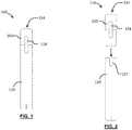
- FIGS 1 and 2 illustrate a smoking substitute system 110.
- the system 110 comprises a main body 120 of the system 110, and a smoking substitute apparatus in the form of a consumable (or "pod") 150.
- the consumable 150 (sometimes referred to herein as a smoking substitute apparatus) is removable from the main body 120, so as to be a replaceable component of the system 110.
- the system 110 is a closed system in the sense that it is not intended that the consumable should be refillable with e-liquid by a user.
- the consumable 150 is configured to engage the main body 120.
- Figure 1 shows the main body 120 and the consumable 150 in an engaged state
- Figure 2 shows the main body 120 and the consumable 150 in a disengaged state.
- a portion of the consumable 150 is received in a cavity of corresponding shape in the main body 120 and is retained in the engaged position by way of a snap-engagement mechanism.
- the main body 120 and consumable 150 may be engaged by screwing one into (or onto) the other, or through a bayonet fitting, or by way of an interference fit.
- the consumable 150 is a "single-use" consumable 150.
- the term "single-use" does not necessarily mean the consumable is designed to be disposed of after a single smoking session. Rather, it defines that the consumable 150 is not designed to be refilled, and is instead disposed of and replaced after usage.
- the system 110 is configured to vaporise an aerosol precursor, which in the illustrated embodiment is a nicotine-based liquid impregnated into a substrate 160.
- the nicotine-impregnated substrate 160 may be referred to as an aerosol generator.
- the nicotine is vaporised and entrained in the airflow to thereby be delivered to a user.
- the vapour or aerosol produced by the aerosol generator is less visible than that produced by a conventional e-liquid from an e-cigarette when exhaled by a user.
- the vapour or aerosol generated by the aerosol generator is invisible or substantially invisible when exhaled by a user.
- the main body provides a handle by which a user may hold the system 110, but provides no functional contribution to the vaporisation of the aerosol precursor.
- a substrate 160 may be impregnated with nicotine by immersion in a solution of nicotine in a volatile carrier solvent (e.g. ethanol) such that the substrate 160 is evenly soaked.
- a volatile carrier solvent e.g. ethanol
- the substrate 160 can then be removed and left to dry or baked in an oven, meaning that the carrier is evaporated and the nicotine is left evenly spread throughout the substrate.
- the nicotine-impregnated substrate 160 may be provided within a consumable 150. In such an embodiment, when the supply of nicotine in the nicotine-impregnated substrate 160 is depleted, the consumable 150 may be replaced. In other embodiments, the nicotine-impregnated substrate 160 itself may be a consumable component of the system 110. For example, the nicotine-impregnated substrate may be locatable within and removable from the system 110.
- Suitable materials and methods for manufacturing air permeable substrates are disclosed, for example, in US4800903 , US4284089 , US4813437 , and US5167242 , the entire contents of which are incorporated herein by reference.
- US4800903 discloses that preferred materials for a polymeric plug are olefinic polymers, and preferably polyethylene or polypropylene, most preferably high density polyethylene.
- Use of high density polyethylene is preferred over, for example, amorphous polyethylene, since it provides a balance between ease of manufacturing and capacity for reversible nicotine absorption.
- polystyrene and polycarbonate are dissolved by nicotine, rendering them unsuitable for forming a nicotine impregnated substrate.
- polymers containing halogens or nitrogen or sulphur are undesirable since they can produce noxious fumes.
- an air permeable substrate that provides an equivalent resistance to draw to that of a conventional cigarette.
- US4284089 discloses that a non-combustible cigarette with a draw resistance approximating that of a conventional cigarette would permit about 35 millilitres of air to be drawn through it during a 2 second period.
- a substrate may be impregnated with nicotine by a variety of methods.
- US4800903 indicates that liquid nicotine, nicotine vapour or a solution of nicotine may be used, and suggests that a solution of nicotine in supercritical liquid carbon dioxide may advantageously be used to impregnate the substrate.
- the substrate may be impregnated with nicotine via immersion in a liquid containing nicotine and a volatile carrier (for example a solution of nicotine in ethanol). The substrate is immersed to evenly soak the substrate. Once the substrate is removed from the liquid it can be left to dry or baked in an oven, evaporating away the carrier so that the nicotine is left evenly distributed throughout the substrate.
- US5167242 discloses that a polyethylene plug can be charged or loaded with a mixture of nicotine, menthol and ethanol in a weight ratio (nicotine:menthol:ethanol) of about 10:1:120 or 10:1:160.
- the menthol and nicotine are sequentially added to the ethanol in a mixing vessel to produce a solution.
- the plugs are placed in a vacuum dryer, which is partially evacuated to create a lower internal pressure than that of the mixing vessel, allowing the nicotine/ethanol/methanol solution to be sucked into the vacuum dryer.
- the plugs remain immersed in the solution within the vacuum dryer for 10 minutes, after which the temperature is raised and the vacuum pump is started to evaporate the ethanol.
- the vacuum dryer is then filled with nitrogen, and a nitrogen atmosphere is maintained for the remainder of the packaging procedure to prevent oxygen contamination of the nicotine.
- the air-permeable substrate may be formed in a different manner.
- the air-permeable substrate may be formed from tobacco.
- the tobacco may be leaf tobacco, tobacco derivatives, expanded tobacco, shredded tobacco, reconstituted tobacco or tobacco substitutes.
- the tobacco has a relatively low moisture content, for example less than 10wt% moisture.
- a typical minimum moisture content for the tobacco is not less than 4wt% moisture.
- Such low moisture content tobacco when exposed to heated air, would typically not produce a substantial vapour. Accordingly, such an air-permeable substrate may be loaded with a source of an active ingredient, as described above.
- the active agent may be applied to the air-permeable substrate by mixing and/or dissolving the active agent in a suitable carrier liquid such as a solvent (e.g. water, ethanol, PG, glycerine, macrogol, caster oil, paraffin, (and derivatives thereof)).
- a suitable carrier liquid such as a solvent (e.g. water, ethanol, PG, glycerine, macrogol, caster oil, paraffin, (and derivatives thereof)).
- the air is typically heated to a suitable temperature.
- This temperature may be at least 30°C. This is in order to promote vaporisation of the active ingredient.
- the temperature is typically not greater than 80°C, or typically not greater than 70°C. This is in order to promote user comfort. It may also reduce or prevent the degradation of the air-permeable substrate and/or the active ingredient.
- FIG 3 shows a schematic longitudinal cross-sectional view of the aerosol generator which forms part of the substitute smoking system shown in Figures 1 and 2 .
- the nicotine-impregnated substrate 160 is arranged within a passage 170.
- the passage 170 extends between an aerosol generator inlet 172 and an aerosol generator outlet 174 at opposing ends of the consumable 150.
- the passage 170 comprises an upstream end at the end of the consumable 150 that engages with the main body 120, and a downstream end at an opposing end of the consumable 150 that comprises a mouthpiece 154 of the system 110.
- a plurality of device air inlets 176 are formed at the boundary between the casing of the consumable and the casing of the main body.
- the device air inlets 176 are in fluid communication with the aerosol generator inlet 172 through an inlet flow channel 178 formed in the cavity of the main body which is of corresponding shape to receive a part of the consumable 150. Air from outside of the system 110 can therefore be drawn into the passage 170 through the device air inlets 176 and the inlet flow channels 178.
- a user can inhale (i.e. take a puff) via the mouthpiece 154 so as to draw air through the passage 170, and so as to form an airflow (indicated by the dashed arrows in Figure 3 ) in a direction from the aerosol generator inlet 172 to the aerosol generator outlet 174.
- Air is thereby drawn through and/or around the nicotine-impregnated substrate 160, such that nicotine from the nicotine-impregnated substrate 160 can be entrained in the airflow.
- the nicotine-impregnated substrate 160 is arranged to extend across a cross-section of at least a portion of the passage 170, such that substantially all of the air drawn through the passage 170 passes through at least a part of the reservoir 160.
- the resistance to drawing air through the consumable 150 may be configured by altering the air permeability of the nicotine-impregnated substrate, or by the provision of one or more bypass passages separate from the passage 170 (not illustrated).
- a non-electrical heat source 200 is arranged upstream of the nicotine-impregnated substrate 160.
- the non-electrical heat source 200 generates heat to heat the air in the passage 170a by an exothermic reaction.
- the heat source 200 may be a replaceable component of the smoking substitute apparatus 150.
- the smoking substitute apparatus 150 may therefore define a receptacle or space into which a replacement non-electrical heat source 200 may be placed once the reaction has completed.
- the consumable 150 may comprise one or more non-replaceable reaction chambers, in which case the entire consumable 150 is intended to be replaced.
- a receptacle for the non-electrical heat source 200 may be provided in the main body 120.
- the main body 120 further comprises a main body passage 70, having a main body inlet 72 and a main body outlet 74 in fluid communication with the inlet 172 of passage 170 of the consumable 150, the main body passage 70 following a path through or around the non-electrical heat source 200, as illustrated in Figure 4 .
- the passage section 170a between the inlet 172 and the nicotine impregnated substrate 160, which may be referred to as the heat source air passage 170a, is configured to follow a convoluted (or at least nonlinear) path through or around the heat source 200.
- the distance travelled by air along the passage section 170a (which may be referred to as the path length of the passage section 170a) is therefore greater than the separation distance (measured along a straight line) between the inlet of the passage section 170a and the outlet of the passage section 170a on the heat source 200.
- a greater path length to separation distance may be advantageous for improved heat transfer between the heat source 200 and the air in the passage section 170a.
- the path length may be greater than 1.1 times the separation distance, preferably greater than 1.5 times the separation distance, greater than 2 times the separation distance, greater than 5 times the separation distance or greater than 10 times the separation distance.
- Increasing the path length may require the passage section 170a to be narrowed, and may therefore create a higher than desirable resistance to draw for the smoking substitute apparatus. Therefore, the path length may be less than 100 times the separation distance, preferably less than 80 times the separation distance, or less than 50 times the separation distance, or less than 20 times the separation distance.
- the heat source 200 may be cylindrical, and the passage section 170a may be shaped to form a helical path around or through the heat source 200, as illustrated in Figure 5 .
- the passage section 170a may be divided into a plurality of separate (i.e. unconnected) helical passage sections 170a around the heat source 200.
- the cross-sectional area of the convoluted section of passage 170a may vary along its length.
- the cross-sectional shape of the convoluted section of passage 170a may be, for example, circular, elliptical, or semi-circular.
- the passage section 170a may be formed as part of the body of the smoking substitute apparatus 150.
- the passage section 170a may be defined within the wall of the receptacle or the reaction chamber for the non-electrical heat source 200.
- a replaceable non-electrical heat source 200 may comprise a container or case for a reaction chamber in which the exothermic reaction takes place, and this case may define the passage section 170a.
- the passage section may be moulded into the body of the smoking substitute apparatus or a container or case for the non-electrical heat source 200.
- the heat source 200 is operable to generate heat utilising an exothermic reaction.
- an exothermic reaction may be, for example, a crystallisation of a super-saturated solution.
- Suitable exothermic reactions include, for example, crystallisation of an aqueous solution of sodium acetate. Such reactions may be reversible, for example by heating of the solution to restore the super-saturated state. In some embodiments, therefore, the heat source 200 may be reusable.
- a reaction between two or more chemicals may provide an exothermic reaction.
- a reaction between lime and aluminium, between calcium oxide and water, between aluminium and silicon dioxide may be utilised.
- a reaction between iron powder and atmospheric oxygen may be employed, optionally in the presence of activated charcoal, vermiculite, and/or sodium chloride.
- Such reactions are, in practical use of the present embodiments, non-reversible, and a heat source 200 of this type is therefore consumable.
- a user of the smoking substitute apparatus 150 may operate the heat source 200 by initiating the exothermic reaction.
- the user may initiate the exothermic reaction prior to inserting the heat source 200 into the receptacle of the smoking substitute apparatus.
- the user may then wait until a defined time period has passed before drawing air through the smoking substitute apparatus 150, allowing the heat source 200 to reach a desired temperature.
- the smoking substitute apparatus 150 or the heat source 200 may comprise a means for indicating to the user that a suitable temperature has been reached.
- an indicator may be provided that changes colour in accordance with the temperature of the heat source 200.
- Such an indicator may be a non-electrical means for indicating temperature, and may be, for example, a thermochromic element or a thermochromic coating on an exterior surface of the heat source 200 or the smoking substitute apparatus 150.
- a user of the smoking substitute apparatus 150 may activate or commence the exothermic reaction by various processes, according to the type of reaction utilised.
- a crystallisation reaction may be activated using a convex or concave metallic disc 210 situated inside the chemical container.
- the metallic disc 210 is inverted (i.e. flexed from concave to convex) to initiate the crystallisation reaction. More generally, the crystallisation reaction may be initiated by operation of a multistable (e.g. bistable) trigger element, one example of which is a concave-convex metallic disc mentioned above.
- the disc 210 may be inverted by the user pressing or bending the disc.
- the disc may be inverted by the use of a plunger or piston 212, as illustrated in Figure 6 . Where two components are required to mix, this may be activated by piercing or removing a separator between the containers of the respective components. Where a reaction such as oxidation of iron powder by atmospheric oxygen is used, a tab, lid, or seal may be removed or pierced to allow air to react with the iron powder.
- the passageway 170 may comprise one or more one-way valves 166.
- the one or more valves are provided to prevent, substantially prevent or reduce airflow from a downstream to upstream direction along the passageway 170.
- two valves 166 are located immediately upstream and immediately downstream, respectively, of the nicotine-impregnated substrate 160.
- only one valve 166 may be provided.
- a valve 166 may be located upstream of the heater 164.
- the valves may be omitted.
Abstract
An aerosol delivery system (110) comprising an air inlet (172), an outlet (174), and an air passage (170) extending from the air inlet (172) to the outlet (174). A part of the air passage is defined by a heat source air passage (170a) extending through a heat source (200) operable to heat air in the heat source air passage (170a) through an exothermic reaction. A reservoir (160) formed from an air-permeable substrate is arranged to allow air in the air passage drawn from the outlet (174) of the air passage (170) to be drawn through the reservoir (160) and on to the outlet (174), the reservoir (160) being loaded with a source of nicotine. The heat source air passage (170a) has a heat source air inlet and a heat source air outlet, spaced apart on the heat source (200) by a separation distance. In use, the heat source air passage (170a) conveys air along a flow path within the heat source (200) from the heat source air inlet to the heat source air outlet, wherein the length of the flow path is greater than the separation distance.
Description
- The present invention relates to an aerosol delivery system. Such a system is of particular, but not necessary exclusive interest as a smoking substitute system. It is a preferred feature of operation of the system that it is able to deliver an active ingredient (such as nicotine) to a user for inhalation without producing a visible vapour cloud.
- The smoking of tobacco is generally considered to expose a smoker to potentially harmful substances. It is thought that a significant amount of the potentially harmful substances are generated through the burning and/or combustion of the tobacco and the constituents of the burnt tobacco in the tobacco smoke itself.
- Low temperature combustion of organic material such as tobacco is known to produce tar and other potentially harmful by-products. There have been proposed various smoking substitute systems in which the conventional smoking of tobacco is avoided.
- Such smoking substitute systems can form part of nicotine replacement therapies aimed at people who wish to stop smoking and overcome a dependence on nicotine.
- Known smoking substitute systems include electronic systems that permit a user to simulate the act of smoking by producing an aerosol (also referred to as a "vapour") that is drawn into the lungs through the mouth (inhaled) and then exhaled. The inhaled aerosol typically bears nicotine and/or a flavourant without, or with fewer of, the health risks associated with conventional smoking.
- In general, smoking substitute systems are intended to provide a substitute for the rituals of smoking, whilst providing the user with a similar, or improved, experience and satisfaction to those experienced with conventional smoking and with combustible tobacco products.
- The popularity and use of smoking substitute systems has grown rapidly in the past few years. Although originally marketed as an aid to assist habitual smokers wishing to quit tobacco smoking, consumers are increasingly viewing smoking substitute systems as desirable lifestyle accessories. There are a number of different categories of smoking substitute systems, each utilising a different smoking substitute approach. Some smoking substitute systems are designed to resemble a conventional cigarette and are cylindrical in form with a mouthpiece at one end. Other smoking substitute devices do not generally resemble a cigarette (for example, the smoking substitute device may have a generally box-like form, in whole or in part).
- One approach is the so-called "vaping" approach, in which a vaporisable liquid, or an aerosol former, sometimes typically referred to herein as "e-liquid", is heated by a heating device (sometimes referred to herein as an electronic cigarette or "e-cigarette" device) to produce an aerosol vapour which is inhaled by a user. The e-liquid typically includes a base liquid, nicotine and may include a flavourant. The resulting vapour therefore also typically contains nicotine and/or a flavourant. The base liquid may include propylene glycol and/or vegetable glycerine.
- A typical e-cigarette device includes a mouthpiece, a power source (typically a battery), a tank for containing e-liquid and a heating device. In use, electrical energy is supplied from the power source to the heating device, which heats the e-liquid to produce an aerosol (or "vapour") which is inhaled by a user through the mouthpiece.
- E-cigarettes can be configured in a variety of ways. For example, there are "closed system" vaping smoking substitute systems, which typically have a sealed tank and heating element. The tank is prefilled with e-liquid and is not intended to be refilled by an end user. One subset of closed system vaping smoking substitute systems include a main body which includes the power source, wherein the main body is configured to be physically and electrically couplable to a consumable including the tank and the heating element. In this way, when the tank of a consumable has been emptied of e-liquid, that consumable is removed from the main body and disposed of. The main body can then be reused by connecting it to a new, replacement, consumable. Another subset of closed system vaping smoking substitute systems are completely disposable, and intended for one-use only.
- There are also "open system" vaping smoking substitute systems which typically have a tank that is configured to be refilled by a user. In this way the entire device can be used multiple times.
- An example vaping smoking substitute system is the myblu™ e-cigarette. The myblu™ e-cigarette is a closed system which includes a main body and a consumable. The main body and consumable are physically and electrically coupled together by pushing the consumable into the main body. The main body includes a rechargeable battery. The consumable includes a mouthpiece and a sealed tank which contains e-liquid. The consumable further includes a heater, which for this device is a heating filament coiled around a portion of a wick. The wick is partially immersed in the e-liquid, and conveys e-liquid from the tank to the heating filament. The system is controlled by a microprocessor on board the main body. The system includes a sensor for detecting when a user is inhaling through the mouthpiece, the microprocessor then activating the device in response. When the system is activated, electrical energy is supplied from the power source to the heating device, which heats e-liquid from the tank to produce a vapour which is inhaled by a user through the mouthpiece.
- An alternative to vaping-type smoking substitute systems is an inhaler apparatus, of which a particular example is the Nicorette® inhalator (trade name). Such systems are often passive in the sense that they do not require a source of heat or other activation energy in order to generate a vapour. As with an e-cigarette, such an inhaler typically includes a mouthpiece and a main body containing a source of nicotine. In use, a user may inhale or "puff' on the mouthpiece to draw air over or through the nicotine source. The nicotine source may be, for example, an air-permeable substrate impregnated with nicotine. When the supply of nicotine in the nicotine source is depleted, such that the user no longer receives sufficient (or any) nicotine with each puff, the user can replace the nicotine source in order to continue nicotine delivery.
- Smoking substitute systems (e.g. e-cigarettes) are generally regarded as having fewer of the health risks associated with conventional smoking, not only for the user themselves, but also for those nearby (i.e. those affected by passive smoking). However, the exhaling of a visible vapour cloud by the user may still be regarded in some circumstances as socially unacceptable, in light of the negative views surrounding smoking itself. Therefore, many locations where smoking is not permitted also do not allow smoking substitute systems, instead requiring users to use the same designated smoking areas as smokers themselves. This can reduce the attractiveness of smoking substitute systems, and reduce their uptake as a smoking cessation aid.
- Accordingly, it would be advantageous to provide a smoking substitute system that can provide a similar user experience to an e-cigarette, but without producing a visible vapour cloud. Alternatively or additionally, it would be advantageous to provide a smoking substitute system that can allow a user to select whether or not the system produces a vapour cloud by switching between one system operating mode where a vapour cloud is produced and another system operating mode where a vapour cloud is not produced.
- Still further, based on the insight of the present inventors, it would be advantageous to provide an aerosol delivery system, not necessarily limited to a smoking substitute system, for the delivery of an active ingredient to a user by inhalation, providing the beneficial effects referred to above.
- The present disclosure has been devised in the light of the above considerations.
- In a general aspect, the present invention relates to an aerosol delivery system with a non-electrical heat source, wherein an air passage around or through the heat source follows an extended path.
- According to a first preferred aspect there is provided an aerosol delivery system comprising an air inlet, an outlet, and an air passage extending from the air inlet to the outlet. A part of the air passage is defined by a heat source air passage extending through a heat source operable to heat air in the heat source air passage through an exothermic reaction. A reservoir formed from an air-permeable substrate is arranged to allow air in the air passage drawn from the outlet of the air passage to be drawn through the reservoir and on to the outlet, the reservoir being loaded with a source of an active ingredient. The heat source air passage has a heat source air inlet and a heat source air outlet, spaced apart on the heat source by a separation distance, wherein, in use, the heat source air passage conveys air along a flow path within the heat source from the heat source air inlet to the heat source air outlet, and wherein the length of the flow path is greater than the separation distance.
- In some embodiments, the aerosol delivery system is a smoking substitute system. In such embodiments, the active ingredient may comprise or consist of nicotine.
- The provision of a heat source air passage of this configuration allows improved heating of the air flowing through the heat source air passage, by providing a greater flow path length proximate to the heat source.
- Optionally, the length of the flow path may be not less than 1.1 times the separation distance, preferably not less than 1.5 times the separation distance, not less than 2 times the separation distance, not less than 5 times the separation distance or not less than 10 times the separation distance.
- A higher ratio of flow path length to separation distance can improve the heat transfer between the heat source and the air in the heat source passage.
- Conveniently, the length of the flow path may be less than 100 times the separation distance, preferably less than 80 times the separation distance, or less than 50 times the separation distance, or less than 20 times the separation distance.
- A lower ratio of flow path length to separation distance can provide a less restrictive flow path, by allowing a larger cross-sectional area configuration for the heat source air passage, reducing the effect of the heat source air passage on the overall resistance to draw for the smoking substitute apparatus.
- Advantageously, the heat source air passage conveys air along a tortuous flow path. A torturous flow path may comprise one or more loops or turns or corners or may be, for example, a helical flow path, or a serpentine flow path.
- Optionally, the aerosol delivery system may comprises a plurality of separate heat source air passages. At least two of the heat source air passages may extend from a common heat source air inlet. At least two of the heat source air passages may extend to a common heat source air outlet.
- Optionally, the exothermic reaction of the heat source may be a crystallisation of a super-saturated solution. The exothermic reaction of the heat source may be initiable by operation of a multistable trigger element or bistable trigger element. Advantageously, the bistable trigger element might be a metallic disc which is operable by inversion from a convex configuration to a concave configuration and/or a concave configuration to a convex configuration. The metallic disc may be invertable using a lever movable in contact with the metallic disc.
- In some embodiments, the exothermic reaction of the heat source may be an oxidation reaction. The oxidation reaction may be a reaction between iron powder and oxygen. The oxygen may be atmospheric oxygen. Conveniently, the exothermic reaction may be initiable by removal of an oxygen impermeable seal from a reaction chamber of the heat source.
- In some embodiments, the exothermic reaction of the heat source may be a reaction between two or more substances stored inside the heat source and initiable by contact between the two or more substances. The contact between the two or more substances may comprise mixing of the two substances. Such mixing may be by diffusion. Additionally or alternatively, the mixing may be caused or improved by agitation of the heat source, for example by shaking of the heat source or smoking substitute system.
- In some embodiments, the heat source may be a replaceable component of the smoking substitute system.
- According to a second preferred aspect of the invention, there is provided a kit of parts for an aerosol delivery system, comprising a base unit, an aerosol delivery apparatus removably engageable with the base unit, and the heat source. The aerosol delivery apparatus is a cartridge configured for engagement with the base unit, the cartridge comprising the reservoir.
- Optionally, in use, the heat source may be comprised within the base unit.
- Conveniently, in use, the heat source may be comprised within the aerosol delivery apparatus.
- According to a third preferred aspect of the invention, there is provided a method of using an aerosol delivery system according to the first aspect, comprising the steps of initiating the exothermic reaction, and drawing air through the passage to generate heated air in the heat source air passage and through the reservoir to generate a vapour.
- The aerosol delivery apparatus may be in the form of a consumable. The consumable may be configured for engagement with a main body. When the consumable is engaged with the main body, the combination of the consumable and the main body may form an aerosol delivery system such as a closed smoking substitute system. For example, the consumable may comprise components of the system that are disposable, and the main body may comprise non-disposable or non-consumable components (e.g. power supply, controller, sensor, etc.) that facilitate the generation and/or delivery of aerosol by the consumable. In such an embodiment, an aerosol precursor (e.g. e-liquid) and/or other nicotine source (e.g. nicotine-infused air-permeable substrate) may be replenished by replacing a used consumable with an unused consumable.
- Alternatively, the aerosol delivery apparatus may be a non-consumable apparatus (e.g. that is in the form of an open aerosol delivery system). In such embodiments an aerosol former (e.g. e-liquid) of the system may be replenished by re-filling, e.g. a reservoir of the aerosol delivery apparatus, with the aerosol precursor (rather than replacing a consumable component of the apparatus).
- In light of this, it should be appreciated that some of the features described herein as being part of the aerosol delivery apparatus may alternatively form part of a main body for engagement with the aerosol delivery apparatus. This may be the case in particular when the aerosol delivery apparatus is in the form of a consumable.
- Where the aerosol delivery apparatus is in the form of a consumable, the main body and the consumable may be configured to be physically coupled together. For example, the consumable may be at least partially received in a recess of the main body, such that there is an interference fit between the main body and the consumable. Alternatively, the main body and the consumable may be physically coupled together by screwing one onto the other, or through a bayonet fitting, or the like.
- Thus, the aerosol delivery apparatus may comprise one or more engagement portions for engaging with a main body. In this way, one end of the aerosol delivery apparatus may be coupled with the main body, whilst an opposing end of the aerosol delivery apparatus may define a mouthpiece of the aerosol delivery system.
- In order to generate an aerosol, the air-permeable substrate comprises at least one volatile compound that is intended to be vaporised/aerosolised and that may provide the user with a recreational, wellness, nutritional, physiological and/or medicinal effect when inhaled. Such a volatile compound is referred to herein as an "active agent" or "active ingredient".
- The active ingredient may comprise or consist of nicotine. However, in some embodiments, the active ingredient may not comprise nicotine, and may instead comprise or consist of one or more of a nutritional agent, a pharmaceutical agent or a flavour agent.
- Suitable active agents include the group consisting of: nicotine, cocaine, caffeine (anhydrous or salts thereof), vitamins, minerals, amino acids, plant or herbal concentrated extracts, sugars, opiates and opioids, cathine and cathinone, kavalactones, mysticin, beta-carboline alkaloids, salvinorin A, cannabinoids, phytocannabinoids, one or more flavourants, together with any combinations, functional equivalents to, and/or synthetic alternatives of the foregoing.
- Example flavourants may include menthol, liquorice, chocolate, fruit flavour (including e.g. citrus, cherry etc.), vanilla, spice (e.g. ginger, cinnamon) and tobacco flavour.
- Cannabinoid compounds include phyto-cannabinoids which include:
- cannabidiol (CBD) and its derivatives/homologues (e.g. cannabidiol mono(m)ethyl ether, cannabidivarin (CBDV), cannabidiorcol, cannabidiolic acid, cannabidivarinic acid);
- cannabinodiol (CBND) and its derivatives/homologues (e.g. carrabinodivarin);
- cannabigerol (CBG) and its derivatives/homologues (e.g. cannabigerol mono(m)ethyl ether, cannabinerolic acid A, cannabigerovarin, cannabigerolic acid A, cannabigerolic acid A mono(m)ethyl ether, cannabigerovarinic acid A);
- cannabinol (CBN) and its derivatives/homologues (e.g. cannabivarin/cannabivarol (CBV), cannabiorcol, cannabinolic acid, cannabinol (m)ethyl ester);
- tetrahydrocannabinol (THC) and its derivatives/homologues (e.g. tetrahydrocannabivarin (THCV), tetrahydrocannabiorcol, tetrahydrocannabinolic acid A/B, tetrahydrocannabivarinic acid A, tetrahydrocannabiorcolic acid A/B, isotetrahydrocannabinol, isotetrahydrocannabivarin);
- cannabicyclol (CBL) and its derivatives/homologues (e.g. cannabicyclolic acid, cannabicyclovarin);
- cannabichromene (CBC) and its derivatives/homologues (e.g. cannabichromenic acid A, cannabichromevarin (CBCV), cannabichromevarinic acid A);
- cannabielsoin (CBE) and its derivatives/homologues (e.g. cannabielsoic acid A/B, cannabiglendol, dehydrocannabifuran, cannabifuran);
- cannabicitran (CBT) and its derivatives/homologues;
- cannabitriol and its derivatives/homologues (e.g. ethyl cannabitriol, dihydroxytetrahydrocannabinol, cannabidiolic acid A cannabitriol ester, dihydroxy-hexahydrocannabinol (cannabiripsol), cannabitetrol, oxo-tetrahydrocannabinol); and
- cannabichromanone (CBCN) and its derivatives/homologues (e.g. cannabicoumaronone).
- In some embodiments, the cannabinoid compound is selected from at least one of cannabidiol (CBD) and its derivatives/homologues e.g. cannabiodiol-Cs (CBD-C5), cannabidiol-C4 (CBD-C4), cannabidiol mono(m)ethyl ether (CBDM-C5), cannabidivarin (CBDV-C3), cannabidiorcol (CBD-C1), cannabidiolic acid (CBDA-C5), cannabidivarinic acid (CBDVA-C3).
- In some embodiments, the cannabinoid compound is selected from at least one of tetrahydrocannabinol (THC) and its derivatives/homologues, e.g. Δ9-tetrahydrocannabinol (Δ9-THC-C5 / cis-Δ9-THC-C5), Δ8-tetrahydrocannabinol (Δ8-THC-C5), Δ8-tetrahydrocannabinolic acid A (Δ8-THCA-C5 A), Δ9-tetrahydrocannabinol-C4 (Δ9-THC-C4), Δ9-tetrahydrocannabivarin (Δ9-THCV-C3), Δ9-tetrahydrocannabiorcol (Δ9-THCO-C1), Δ9-tetrahydrocannabinolic acid A (Δ9-THCA-C5A), Δ9-tetrahydrocannabinolic acid B (Δ9-THCA-C5 B), Δ9-tetrahydrocannabinolic acid-C4 A and/or B (Δ9-THCA-C4A and/or B), Δ9-tetrahydrocannabivarinic acid A (Δ9-THCVA-C3 A), Δ9-tetrahydrocannabiorcolic acid A and/or B (Δ9-THCOA-C1 A and/or B), isotetrahydrocannabinol and isotetrahydrocannabivarin.
- The total amount of cannabinoid compounds in the substrate may be at least 200 mg; for example, it may be at least 250 mg, at least 300 mg, at least 400 mg, at least 500 mg. In some cases, lower amounts may be preferred. The total amount of cannabinoid compounds in the substrate may therefore be at least 10 mg, at least 20 mg, at least 30 mg, at least 40 mg, at least 50 mg, at least 75 mg, at least 100 mg.
- In some cases, it may be desirable to limited the total amount of cannabinoid compounds, which may be not more than 200 mg, not more than 175 mg, not more than 150 mg, not more than 125 mg, not more than 100 mg, not more than 75 mg, not more than 50 mg, not more than 40 mg, not more than 30 mg, not more than 20 mg, not more than 10 mg. In some cases, the total amount of the cannabinoid compounds may be not more than 5 mg.
- Where THC is included, either as one cannabinoid compound in a mixture or as the only cannabinoid, the total of amount of THC may be limited. In some cases, the total amount of THC in the substrate is not more than 100 mg, not more than 75 mg, not more than 50 mg, not more than 40 mg, not more than 30 mg, not more than 20 mg, not more than 15 mg, not more than 10 mg, not more than 5 mg, not more than 3 mg. In some cases, the amount of THC may be 0.1 to 30 mg, for example 1 to 30 mg, for example 1 to 20 mg, for example 1 to 10 mg, for example 1 to 5 mg, for example 1 to 3 mg.
- The aerosol delivery apparatus may comprise a reservoir configured to store an aerosol precursor. The aerosol precursor may be formulated so as to produce a non-visible or substantially non-visible vapour. The aerosol precursor may comprise a base liquid. The aerosol precursor may additionally comprise nicotine. The aerosol precursor may be an e-liquid. The aerosol precursor may consist substantially of nicotine or a nicotine compound. The aerosol precursor may further comprise a flavourant. Alternatively, the aerosol precursor may be substantially flavourless. That is, the aerosol precursor may not contain any deliberately added additional flavourant. A flavourant may be provided as a separate flavourant aerosol precursor, such that the aerosol precursor and flavourant aerosol precursor may be separately vaporised to form an aerosol comprising both the aerosol precursor and the flavourant aerosol precursor.
- The reservoir configured to store the aerosol precursor and/or the flavourant aerosol precursor may consist of an air-permeable substrate impregnated with the aerosol precursor and/or the flavourant aerosol precursor. The substrate material may be a foamed polymer which will allow for airflow to pass through the substrate at a given pressure drop value, so as to provide a comfortable 'draw' sensation for the user. The substrate may be, for example, a sintered polyethylene or a PET foam.
- The substrate may be impregnated with nicotine via immersion in a liquid containing nicotine and a volatile carrier (for example a solution of nicotine in ethanol). The substrate is immersed to evenly soak the substrate. Once removed and left to dry or baked in an oven, the carrier is evaporated and the nicotine is left evenly spread throughout the substrate.
- The aerosol precursor and/or the flavourant aerosol precursor may be formulated to form a vapour when ambient air is drawn through the reservoir. Alternatively, the aerosol precursor and/or the flavourant aerosol precursor may be formulated to form a vapour when heated air is drawn through the reservoir. The reservoir may comprise a monolithic substrate. The reservoir may consist of a plurality of substrates, each arranged to allow air to be drawn therethrough, and each comprising one or both of an aerosol precursor and the flavourant aerosol precursor. The aerosol precursor and/or the flavourant aerosol precursor may be provided in spatially coterminous or spatially distinct regions of the reservoir.
- Alternatively, the aerosol precursor reservoir may be in the form of a tank. At least a portion of the tank may be light-transmissive. For example, the tank may comprise a window to allow a user to visually assess the quantity of aerosol precursor in the tank. A housing of the aerosol delivery apparatus may comprise a corresponding aperture (or slot) or window that may be aligned with a light-transmissive portion (e.g. window) of the tank. The reservoir may be referred to as a "clearomizer" if it includes a window, or a "cartomizer" if it does not.
- The aerosol delivery apparatus may comprise one or more passages for fluid (e.g. air) flow therethrough. Where more than one passage is present, one or more of the passages may be distinct, such that there is no intersection between the passages. One or more of the passages may comprise junctions or openings therebetween such that fluid within the passages can mix within the aerosol delivery apparatus.
- One or more of the passages may comprise one or more valves to control fluid flow. The valve may be, for example, a one-way valve to ensure fluid (i.e. air) can only flow through the passage in a desired direction. The valve may be operable to open and close the passage such that fluid is enabled to or prevented from flowing through the passage. More than one valve may be linked such that the valves may be operated in combination or in synchronism with each other. A valve to open and close a passage may be controlled by mechanical means (i.e. the user moves the valve using a control lever or similar).
- The passages may extend through (at least a portion of) the aerosol delivery apparatus, between openings that may define an inlet and an outlet of a passage. Each inlet and outlet may be in fluid communication with only one passage, or a subset of the passages, or all the passages in the aerosol delivery apparatus. The outlet or outlets may be at a mouthpiece of the aerosol delivery apparatus. In this respect, a user may draw fluid (e.g. air) into and through a passage by inhaling at the outlet (i.e. using the mouthpiece).
- A passage through the aerosol delivery apparatus may be at least partially defined by a tank forming the aerosol precursor reservoir. The tank may substantially (or fully) define the passage, for at least a part of the length of the passage. In this respect, the tank may surround the passage, e.g. in an annular arrangement around the passage.
- One or more of the fluid passages may comprise a heater for heating the fluid (i.e. air) passing through the passage. The heater may, for example, be arranged upstream of a reservoir formed from an air permeable substrate such that air warmed by the heater is drawn through the reservoir to enable or increase nicotine or flavourant vapourisation and subsequent entrainment in the air-flow. The heater to heat the air may comprise one or more thermally conductive elements to conduct heat from a heater to the air passage or to increase the heat transfer between the heater and the air. The heat source is non-electrical. For example, the heat to heat the air may be generated by an exothermic reaction. An exothermic reaction heat source may comprise a single-use (i.e. consumable) reaction container. Alternatively, an exothermic reaction heat source may be rechargeable (e.g. by using a reversible reaction such as a crystallisation process).
- The term "flavourant" is used to describe a compound or combination of compounds that provide flavour and/or aroma. For example, the flavourant may be configured to interact with a sensory receptor of a user (such as an olfactory or taste receptor). The flavourant may include one or more volatile substances.
- The flavourant may be provided in solid or liquid form. The flavourant may be natural or synthetic. For example, the flavourant may include menthol, liquorice, chocolate, fruit flavour (including e.g. citrus, cherry etc.), vanilla, spice (e.g. ginger, cinnamon) and tobacco flavour. The flavourant may be evenly dispersed or may be provided in isolated locations and/or varying concentrations.
- The air-permeable substrate may comprise plant material. The plant material may comprise least one plant material selected from the list including Amaranthus dubius, Arctostaphylos uva-ursi (Bearberry), Argemone mexicana, Amica, Artemisia vulgaris, Yellow Tees, Galea zacatechichi, Canavalia maritima (Baybean), Cecropia mexicana (Guamura), Cestrum noctumum, Cynoglossum virginianum (wild comfrey), Cytisus scoparius, Damiana, Entada rheedii, Eschscholzia califomica (California Poppy), Fittonia albivenis, Hippobroma longiflora, Humulus japonica (Japanese Hops), Humulus lupulus (Hops), Lactuca virosa (Lettuce Opium), Laggera alata, Leonotis leonurus, Leonurus cardiaca (Motherwort), Leonurus sibiricus (Honeyweed), Lobelia cardinalis, Lobelia inflata (Indian-tobacco), Lobelia siphilitica, Nepeta cataria (Catnip), Nicotiana species (Tobacco), Nymphaea alba (White Lily), Nymphaea caerulea (Blue Lily), Opium poppy, Passiflora incamata (Passionflower), Pedicularis densiflora (Indian Warrior), Pedicularis groenlandica (Elephant's Head), Salvia divinorum, Salvia dorrii (Tobacco Sage), Salvia species (Sage), Scutellaria galericulata, Scutellaria lateriflora, Scutellaria nana, Scutellaria species (Skullcap), Sida acuta (Wireweed), Sida rhombifolia, Silene capensis, Syzygium aromaticum (Clove), Tagetes lucida (Mexican Tarragon), Tarchonanthus camphoratus, Tumera diffusa (Damiana), Verbascum (Mullein), Zamia latifolia (Maconha Brava) together with any combinations, functional equivalents to, and/or synthetic alternatives of the foregoing.
- In some embodiments, the plant material is tobacco. Any type of tobacco may be used. This includes, but is not limited to, flue-cured tobacco, burley tobacco, Maryland Tobacco, dark-air cured tobacco, oriental tobacco, dark-fired tobacco, perique tobacco and rustica tobacco. This also includes blends of the above mentioned tobaccos.
- Any suitable parts of the tobacco plant may be used. This includes leaves, stems, roots, bark, seeds and flowers.
- The tobacco may comprise one or more of leaf tobacco, stem tobacco, tobacco powder, tobacco dust, tobacco derivatives, expanded tobacco, homogenised tobacco, shredded tobacco, extruded tobacco, cut rag tobacco and/or reconstituted tobacco (e.g. slurry recon or paper recon).
- The air-permeable substrate may comprise a gathered sheet of homogenised (e.g. paper/slurry recon) tobacco or gathered shreds/strips formed from such a sheet.
- In some embodiments, the sheet used to form the aerosol-forming substrate has a grammage greater than or equal to 100 g/m2, e.g. greater than or equal to 110 g/m2 such as greater than or equal to 120 g/m2.
- The sheet may have a grammage of less than or equal to 300 g/m2 e.g. less than or equal to 250 g/m2 or less than or equal to 200 g/m2.
- The sheet may have a grammage of between 120 and 190 g/m2.
- The air-permeable substrate may comprise at least 50 wt% plant material, e.g. at least 60 wt% plant material e.g. around 65 wt% plant material. The air-permeable substrate may comprise 80 wt% or less plant material e.g. 75 or 70 wt% or less plant material.
- The air-permeable substrate may comprise one or more additives selected from flavourants, fillers and binders.
- Typically, the air-permeable substrate does not comprise a humectant. Humectants may be provided in heat not burn (HNB) tobacco charges. In such cases, humectants are provided as vapour generators, the generated vapour being used to help carry volatile active compounds and to increase visible vapour. Accordingly, it is preferred that the air-permeable substrate does not comprise one or more humectants such as polyhydric alcohols (e.g. propylene glycol (PG), triethylene glycol, 1,2-butane diol and vegetable glycerine (VG)) and their esters (e.g. glycerol mono-, di- or tri-acetate). If such humectants are present in the air-permeable substrate, they may be present at a low level, such as less than 0.5 wt%, more preferably less than 0.1 wt%.
- Suitable binders are known in the art and may act to bind together the components forming the air-permeable substrate. Binders may comprise starches and/or cellulosic binders such as methyl cellulose, ethyl cellulose, hydroxypropyl cellulose, hydroxyethyl cellulose and methyl cellulose, gums such as xanthan, guar, arabic and/or locust bean gum, organic acids and their salts such as alginic acid/ sodium alginate, agar and pectins.
- Preferably the binder content is 5 to 10 wt% of the air-permeable substrate e.g. around 6 to 8 wt%.
- Suitable fillers are known in the art and may act to strengthen the air-permeable substrate. Fillers may comprise fibrous (non-tobacco) fillers such as cellulose fibres, lignocellulose fibres (e.g. wood fibres), jute fibres and combinations thereof.
- Preferably, the filler content is 5 to 10 wt% of the aerosol-forming substrate e.g. around 6 to 9 wt%.
- The air-permeable substrate may comprise an aqueous and/or non-aqueous solvent. In some embodiments, the air-permeable substrate has a water content of between 4 and 10 wt% e.g. between 6-9 wt% such as between 7-9 wt%. Such low moisture content in the air-permeable substrate typically has the effect that, when the air-permeable substrate is exposed to heated air, there would typically not be produced a substantial visible vapour. It is to be noted that in one embodiment it is possible to use as the air-permeable substrate a low moisture tobacco material with its natural nicotine content. The natural nicotine content then meets the requirements of the active agent.
- The air-permeable substrate may be at least partly circumscribed by a wrapping layer e.g. a paper wrapping layer. The wrapping layer may overlie an inner foil layer or may comprise a paper/foil laminate (with the foil innermost).
- The plant material may comprise cannabis plant material including Cannabis sativa, Cannabis indica and Cannabis rudealis. The plant material may comprise Echinacea purpurea, Echinacea angustifolia, Acmella oleracea, Helichrysum umbraculigerum, or Radula marginata. This also includes blends of the above mentioned plant material.
- In some embodiments, the cannabinoid-containing plant material is cannabis. The plant may be a traditional strain, or may be a strain bred or other modified (e.g. genetically) to produce certain levels of some cannabinoids compounds, e.g. low levels of THC or high levels of THC.
- Any suitable parts of the cannabinoid-containing plant may be used. Thus the cannabinoid-containing plant material may comprise leaves, stems, roots, bark, seeds, buds and flowers (which may be cured).
- The invention includes the combination of the aspects and preferred features described except where such a combination is clearly impermissible or expressly avoided.
- So that the invention may be understood, and so that further aspects and features thereof may be appreciated, embodiments illustrating the principles of the invention will now be discussed in further detail with reference to the accompanying figures, in which:
-
Figure 1 is a schematic front view of a smoking substitute system, according to a first embodiment, in an engaged position; -
Figure 2 is a schematic front view of the smoking substitute system of the first embodiment in a disengaged position; -
Figure 3 is a schematic longitudinal cross sectional view of a smoking substitute apparatus of the first embodiment; -
Figure 4 is a schematic longitudinal cross sectional view of a smoking substitute system having a heat source arranged in a base unit; -
Figure 5 is a schematic longitudinal cross sectional view of heat source and convoluted flow path of the first embodiment; and -
Figure 6 is a schematic longitudinal cross sectional view of a smoking substitute apparatus comprising a metallic disc and a plunger for activation of the heat source. - Further background to the present invention and further aspects and embodiments of the present invention will now be discussed with reference to the accompanying figures. Further aspects and embodiments will be apparent to those skilled in the art. The contents of all documents mentioned in this text are incorporated herein by reference in their entirety.
- The embodiments of the invention are described as smoking substitute systems, in which the active ingredient typically comprises or consists of nicotine. However, on the basis of the present disclosure it will be apparent that the invention can be embodied more generally as an aerosol delivery system. In such aerosol delivery systems the active ingredient may not comprise nicotine, and may instead comprise or consist of one or more of a nutritional agent, a pharmaceutical agent or a flavour agent.
-
Figures 1 and 2 illustrate asmoking substitute system 110. Thesystem 110 comprises amain body 120 of thesystem 110, and a smoking substitute apparatus in the form of a consumable (or "pod") 150. In the illustrated embodiment the consumable 150 (sometimes referred to herein as a smoking substitute apparatus) is removable from themain body 120, so as to be a replaceable component of thesystem 110. Thesystem 110 is a closed system in the sense that it is not intended that the consumable should be refillable with e-liquid by a user. - As is apparent from
Figures 1 and 2 , the consumable 150 is configured to engage themain body 120.Figure 1 shows themain body 120 and the consumable 150 in an engaged state, whilstFigure 2 shows themain body 120 and the consumable 150 in a disengaged state. When engaged, a portion of the consumable 150 is received in a cavity of corresponding shape in themain body 120 and is retained in the engaged position by way of a snap-engagement mechanism. In other embodiments, themain body 120 and consumable 150 may be engaged by screwing one into (or onto) the other, or through a bayonet fitting, or by way of an interference fit. In the illustrated embodiment, the consumable 150 is a "single-use"consumable 150. The term "single-use" does not necessarily mean the consumable is designed to be disposed of after a single smoking session. Rather, it defines that the consumable 150 is not designed to be refilled, and is instead disposed of and replaced after usage. - The
system 110 is configured to vaporise an aerosol precursor, which in the illustrated embodiment is a nicotine-based liquid impregnated into asubstrate 160. The nicotine-impregnatedsubstrate 160 may be referred to as an aerosol generator. When air is drawn through or over the nicotine-impregnatedsubstrate 160, the nicotine is vaporised and entrained in the airflow to thereby be delivered to a user. The vapour or aerosol produced by the aerosol generator is less visible than that produced by a conventional e-liquid from an e-cigarette when exhaled by a user. Preferably, the vapour or aerosol generated by the aerosol generator is invisible or substantially invisible when exhaled by a user. In the illustrated embodiment, the main body provides a handle by which a user may hold thesystem 110, but provides no functional contribution to the vaporisation of the aerosol precursor. - A
substrate 160 may be impregnated with nicotine by immersion in a solution of nicotine in a volatile carrier solvent (e.g. ethanol) such that thesubstrate 160 is evenly soaked. Thesubstrate 160 can then be removed and left to dry or baked in an oven, meaning that the carrier is evaporated and the nicotine is left evenly spread throughout the substrate. - The nicotine-impregnated
substrate 160 may be provided within a consumable 150. In such an embodiment, when the supply of nicotine in the nicotine-impregnatedsubstrate 160 is depleted, the consumable 150 may be replaced. In other embodiments, the nicotine-impregnatedsubstrate 160 itself may be a consumable component of thesystem 110. For example, the nicotine-impregnated substrate may be locatable within and removable from thesystem 110. - Further details are now set out relating to the air-permeable substrate and its impregnation with an active ingredient.
-
-
US4800903 discloses that preferred materials for a polymeric plug are olefinic polymers, and preferably polyethylene or polypropylene, most preferably high density polyethylene. Use of high density polyethylene is preferred over, for example, amorphous polyethylene, since it provides a balance between ease of manufacturing and capacity for reversible nicotine absorption. - Meanwhile, some polymers are considered to be inherently unsuitable for use as an air permeable substrate. For example, some polymeric substances such as polystyrene and polycarbonate are dissolved by nicotine, rendering them unsuitable for forming a nicotine impregnated substrate. Furthermore, polymers containing halogens or nitrogen or sulphur are undesirable since they can produce noxious fumes.
- To improve user satisfaction, it may be preferable to use an air permeable substrate that provides an equivalent resistance to draw to that of a conventional cigarette. For example,
US4284089 discloses that a non-combustible cigarette with a draw resistance approximating that of a conventional cigarette would permit about 35 millilitres of air to be drawn through it during a 2 second period. - A substrate may be impregnated with nicotine by a variety of methods. For example,
US4800903 indicates that liquid nicotine, nicotine vapour or a solution of nicotine may be used, and suggests that a solution of nicotine in supercritical liquid carbon dioxide may advantageously be used to impregnate the substrate. Alternatively, the substrate may be impregnated with nicotine via immersion in a liquid containing nicotine and a volatile carrier (for example a solution of nicotine in ethanol). The substrate is immersed to evenly soak the substrate. Once the substrate is removed from the liquid it can be left to dry or baked in an oven, evaporating away the carrier so that the nicotine is left evenly distributed throughout the substrate. -
US5167242 discloses that a polyethylene plug can be charged or loaded with a mixture of nicotine, menthol and ethanol in a weight ratio (nicotine:menthol:ethanol) of about 10:1:120 or 10:1:160. The menthol and nicotine are sequentially added to the ethanol in a mixing vessel to produce a solution. Meanwhile, the plugs are placed in a vacuum dryer, which is partially evacuated to create a lower internal pressure than that of the mixing vessel, allowing the nicotine/ethanol/methanol solution to be sucked into the vacuum dryer. The plugs remain immersed in the solution within the vacuum dryer for 10 minutes, after which the temperature is raised and the vacuum pump is started to evaporate the ethanol. The vacuum dryer is then filled with nitrogen, and a nitrogen atmosphere is maintained for the remainder of the packaging procedure to prevent oxygen contamination of the nicotine. - In alternative embodiments, the air-permeable substrate may be formed in a different manner. For example, the air-permeable substrate may be formed from tobacco. The tobacco may be leaf tobacco, tobacco derivatives, expanded tobacco, shredded tobacco, reconstituted tobacco or tobacco substitutes. Preferably the tobacco has a relatively low moisture content, for example less than 10wt% moisture. A typical minimum moisture content for the tobacco is not less than 4wt% moisture. Such low moisture content tobacco, when exposed to heated air, would typically not produce a substantial vapour. Accordingly, such an air-permeable substrate may be loaded with a source of an active ingredient, as described above.
- Where the air-permeable substrate is formed for example of tobacco, the active agent may be applied to the air-permeable substrate by mixing and/or dissolving the active agent in a suitable carrier liquid such as a solvent (e.g. water, ethanol, PG, glycerine, macrogol, caster oil, paraffin, (and derivatives thereof)).
- The air is typically heated to a suitable temperature. This temperature may be at least 30°C. This is in order to promote vaporisation of the active ingredient. The temperature is typically not greater than 80°C, or typically not greater than 70°C. This is in order to promote user comfort. It may also reduce or prevent the degradation of the air-permeable substrate and/or the active ingredient.
-
Figure 3 shows a schematic longitudinal cross-sectional view of the aerosol generator which forms part of the substitute smoking system shown inFigures 1 and 2 . InFigure 3 , the nicotine-impregnatedsubstrate 160 is arranged within apassage 170. Thepassage 170 extends between anaerosol generator inlet 172 and anaerosol generator outlet 174 at opposing ends of the consumable 150. In this respect, thepassage 170 comprises an upstream end at the end of the consumable 150 that engages with themain body 120, and a downstream end at an opposing end of the consumable 150 that comprises amouthpiece 154 of thesystem 110. - When the consumable 150 is received in the cavity of the
main body 120 as shown inFigure 3 , a plurality ofdevice air inlets 176 are formed at the boundary between the casing of the consumable and the casing of the main body. Thedevice air inlets 176 are in fluid communication with theaerosol generator inlet 172 through aninlet flow channel 178 formed in the cavity of the main body which is of corresponding shape to receive a part of the consumable 150. Air from outside of thesystem 110 can therefore be drawn into thepassage 170 through thedevice air inlets 176 and theinlet flow channels 178. - When the consumable 150 is engaged with the
main body 120, a user can inhale (i.e. take a puff) via themouthpiece 154 so as to draw air through thepassage 170, and so as to form an airflow (indicated by the dashed arrows inFigure 3 ) in a direction from theaerosol generator inlet 172 to theaerosol generator outlet 174. Air is thereby drawn through and/or around the nicotine-impregnatedsubstrate 160, such that nicotine from the nicotine-impregnatedsubstrate 160 can be entrained in the airflow. The nicotine-impregnatedsubstrate 160 is arranged to extend across a cross-section of at least a portion of thepassage 170, such that substantially all of the air drawn through thepassage 170 passes through at least a part of thereservoir 160. The resistance to drawing air through the consumable 150 may be configured by altering the air permeability of the nicotine-impregnated substrate, or by the provision of one or more bypass passages separate from the passage 170 (not illustrated). - A
non-electrical heat source 200 is arranged upstream of the nicotine-impregnatedsubstrate 160. Thenon-electrical heat source 200 generates heat to heat the air in thepassage 170a by an exothermic reaction. Theheat source 200 may be a replaceable component of thesmoking substitute apparatus 150. Thesmoking substitute apparatus 150 may therefore define a receptacle or space into which a replacementnon-electrical heat source 200 may be placed once the reaction has completed. Alternatively, the consumable 150 may comprise one or more non-replaceable reaction chambers, in which case theentire consumable 150 is intended to be replaced. In some embodiments, a receptacle for thenon-electrical heat source 200 may be provided in themain body 120. In such an embodiment, themain body 120 further comprises a main body passage 70, having amain body inlet 72 and amain body outlet 74 in fluid communication with theinlet 172 ofpassage 170 of the consumable 150, the main body passage 70 following a path through or around thenon-electrical heat source 200, as illustrated inFigure 4 . - The
passage section 170a, between theinlet 172 and the nicotine impregnatedsubstrate 160, which may be referred to as the heatsource air passage 170a, is configured to follow a convoluted (or at least nonlinear) path through or around theheat source 200. The distance travelled by air along thepassage section 170a (which may be referred to as the path length of thepassage section 170a) is therefore greater than the separation distance (measured along a straight line) between the inlet of thepassage section 170a and the outlet of thepassage section 170a on theheat source 200. - A greater path length to separation distance may be advantageous for improved heat transfer between the
heat source 200 and the air in thepassage section 170a. For example, the path length may be greater than 1.1 times the separation distance, preferably greater than 1.5 times the separation distance, greater than 2 times the separation distance, greater than 5 times the separation distance or greater than 10 times the separation distance. Increasing the path length may require thepassage section 170a to be narrowed, and may therefore create a higher than desirable resistance to draw for the smoking substitute apparatus. Therefore, the path length may be less than 100 times the separation distance, preferably less than 80 times the separation distance, or less than 50 times the separation distance, or less than 20 times the separation distance. - This relationship between path length and separation distance for the
passage section 170a may be realised throughdifferent passage section 170a configurations. For example, theheat source 200 may be cylindrical, and thepassage section 170a may be shaped to form a helical path around or through theheat source 200, as illustrated inFigure 5 . In some embodiments, thepassage section 170a may be divided into a plurality of separate (i.e. unconnected)helical passage sections 170a around theheat source 200. The cross-sectional area of the convoluted section ofpassage 170a may vary along its length. The cross-sectional shape of the convoluted section ofpassage 170a may be, for example, circular, elliptical, or semi-circular. - The
passage section 170a may be formed as part of the body of thesmoking substitute apparatus 150. For example, thepassage section 170a may be defined within the wall of the receptacle or the reaction chamber for thenon-electrical heat source 200. Alternatively, a replaceablenon-electrical heat source 200 may comprise a container or case for a reaction chamber in which the exothermic reaction takes place, and this case may define thepassage section 170a. The passage section may be moulded into the body of the smoking substitute apparatus or a container or case for thenon-electrical heat source 200. - The
heat source 200 is operable to generate heat utilising an exothermic reaction. Such an exothermic reaction may be, for example, a crystallisation of a super-saturated solution. Suitable exothermic reactions include, for example, crystallisation of an aqueous solution of sodium acetate. Such reactions may be reversible, for example by heating of the solution to restore the super-saturated state. In some embodiments, therefore, theheat source 200 may be reusable. - Alternatively, a reaction between two or more chemicals may provide an exothermic reaction. For example, a reaction between lime and aluminium, between calcium oxide and water, between aluminium and silicon dioxide may be utilised. In still further embodiments, a reaction between iron powder and atmospheric oxygen may be employed, optionally in the presence of activated charcoal, vermiculite, and/or sodium chloride. Such reactions are, in practical use of the present embodiments, non-reversible, and a
heat source 200 of this type is therefore consumable. - A user of the
smoking substitute apparatus 150 may operate theheat source 200 by initiating the exothermic reaction. In some embodiments, the user may initiate the exothermic reaction prior to inserting theheat source 200 into the receptacle of the smoking substitute apparatus. The user may then wait until a defined time period has passed before drawing air through thesmoking substitute apparatus 150, allowing theheat source 200 to reach a desired temperature. Thesmoking substitute apparatus 150 or theheat source 200 may comprise a means for indicating to the user that a suitable temperature has been reached. For example, an indicator may be provided that changes colour in accordance with the temperature of theheat source 200. Such an indicator may be a non-electrical means for indicating temperature, and may be, for example, a thermochromic element or a thermochromic coating on an exterior surface of theheat source 200 or thesmoking substitute apparatus 150. - A user of the
smoking substitute apparatus 150 may activate or commence the exothermic reaction by various processes, according to the type of reaction utilised. A crystallisation reaction may be activated using a convex or concavemetallic disc 210 situated inside the chemical container. Themetallic disc 210 is inverted (i.e. flexed from concave to convex) to initiate the crystallisation reaction. More generally, the crystallisation reaction may be initiated by operation of a multistable (e.g. bistable) trigger element, one example of which is a concave-convex metallic disc mentioned above. In some embodiments, thedisc 210 may be inverted by the user pressing or bending the disc. In other embodiments, the disc may be inverted by the use of a plunger orpiston 212, as illustrated inFigure 6 . Where two components are required to mix, this may be activated by piercing or removing a separator between the containers of the respective components. Where a reaction such as oxidation of iron powder by atmospheric oxygen is used, a tab, lid, or seal may be removed or pierced to allow air to react with the iron powder. - The
passageway 170 may comprise one or more one-way valves 166. The one or more valves are provided to prevent, substantially prevent or reduce airflow from a downstream to upstream direction along thepassageway 170. InFigure 3 , twovalves 166 are located immediately upstream and immediately downstream, respectively, of the nicotine-impregnatedsubstrate 160. In some embodiments, only onevalve 166 may be provided. In further embodiments, avalve 166 may be located upstream of the heater 164. In still further embodiments, the valves may be omitted. - The features disclosed in the foregoing description, or in the following claims, or in the accompanying drawings, expressed in their specific forms or in terms of a means for performing the disclosed function, or a method or process for obtaining the disclosed results, as appropriate, may, separately, or in any combination of such features, be utilised for realising the invention in diverse forms thereof.
- While the invention has been described in conjunction with the exemplary embodiments described above, many equivalent modifications and variations will be apparent to those skilled in the art when given this disclosure. Accordingly, the exemplary embodiments of the invention set forth above are considered to be illustrative and not limiting. Various changes to the described embodiments may be made without departing from the spirit and scope of the invention.
- For the avoidance of any doubt, any theoretical explanations provided herein are provided for the purposes of improving the understanding of a reader. The inventors do not wish to be bound by any of these theoretical explanations.
- Any section headings used herein are for organizational purposes only and are not to be construed as limiting the subject matter described.
- Throughout this specification, including the claims which follow, unless the context requires otherwise, the words "have", "comprise", and "include", and variations such as "having", "comprises", "comprising", and "including" will be understood to imply the inclusion of a stated integer or step or group of integers or steps but not the exclusion of any other integer or step or group of integers or steps.
- It must be noted that, as used in the specification and the appended claims, the singular forms "a," "an," and "the" include plural referents unless the context clearly dictates otherwise. Ranges may be expressed herein as from "about" one particular value, and/or to "about" another particular value. When such a range is expressed, another embodiment includes from the one particular value and/or to the other particular value. Similarly, when values are expressed as approximations, by the use of the antecedent "about," it will be understood that the particular value forms another embodiment. The term "about" in relation to a numerical value is optional and means, for example, +/- 10%.
- The words "preferred" and "preferably" are used herein refer to embodiments of the invention that may provide certain benefits under some circumstances. It is to be appreciated, however, that other embodiments may also be preferred under the same or different circumstances. The recitation of one or more preferred embodiments therefore does not mean or imply that other embodiments are not useful, and is not intended to exclude other embodiments from the scope of the disclosure, or from the scope of the claims.
Claims (15)
- An aerosol delivery system (110) comprising:an air inlet (172);an outlet (174);an air passage (170) extending from the air inlet (172) to the outlet (174);a part of the air passage being defined by a heat source air passage (170a) extending through a heat source (200) operable to heat air in the heat source air passage (170a) through an exothermic reaction; anda reservoir (160) formed from an air-permeable substrate and arranged to allow air in the air passage drawn from the outlet (174) of the air passage (170) to be drawn through the reservoir (160) and on to the outlet (174), the reservoir (160) being loaded with a source of an active ingredient; whereinthe heat source air passage (170a) has a heat source air inlet and a heat source air outlet, spaced apart on the heat source (200) by a separation distance, wherein, in use, the heat source air passage (170a) conveys air along a flow path within the heat source (200) from the heat source air inlet to the heat source air outlet, and wherein the length of the flow path is greater than the separation distance.
- An aerosol delivery system (110) according to claim 1, wherein:
the heat source air passage (170a) conveys air along a tortuous flow path. - An aerosol delivery system (110) according to either one of claims 1 or 2, wherein:
the smoking substitute system (110) comprises a plurality of separate heat source air passages (170a). - An aerosol delivery apparatus (150) according to claim 3, wherein:
at least two of the heat source air passages (170a) extend from a common heat source air inlet and/or to a common heat source air outlet. - An aerosol delivery system (110) according to any preceding claim, wherein:
the exothermic reaction of the heat source (200) is a crystallisation of a super-saturated solution. - An aerosol delivery system (110) according claim 5, wherein:
the exothermic reaction of the heat source (200) is initiable by operation of a multistable trigger element. - An aerosol delivery system (110) according to any one of claims 1 to 4, wherein:
the exothermic reaction of the heat source (200) is an oxidation reaction. - An aerosol delivery system (110) according to claim 7, wherein:
the exothermic reaction is initiable by removal of an oxygen impermeable seal from a reaction chamber of the heat source (200). - An aerosol delivery system (110) according to any one of claims 1 to 4, wherein:
the exothermic reaction of the heat source (200) is a reaction between two or more substances stored inside the heat source (200) and initiable by contact between the two or more substances. - An aerosol delivery system according to any preceding claim, wherein the aerosol delivery system is a smoking substitute system and the active ingredient is nicotine.
- An aerosol delivery system (110) according to any preceding claim, wherein:
the heat source (200) is a replaceable component of the aerosol delivery system (110). - A kit of parts for an aerosol delivery system (110) according to any preceding claim, comprising:a base unit (120);an aerosol delivery apparatus (150) removably engageable with the base unit (120);and the heat source (200); wherein:
the aerosol delivery apparatus (150) is a cartridge configured for engagement with the base unit (120), the cartridge comprising the reservoir (160). - A kit of parts for an aerosol delivery system (110) according to claim 12, wherein, in use, the heat source (200) is comprised within the base unit (120).
- A kit of parts for an aerosol delivery system (110) according to claim 12, wherein, in use, the heat source (200) is comprised within the aerosol delivery apparatus (150).
- A method of using an aerosol delivery system according to any of claims 1 to 11, comprising the steps of:initiating the exothermic reaction; anddrawing air through the passage to generate heated air in the heat source air passage and through the reservoir to generate a vapour.
Priority Applications (4)
| Application Number | Priority Date | Filing Date | Title |
|---|---|---|---|
| EP20154504.3A EP3858174A1 (en) | 2020-01-30 | 2020-01-30 | Aerosol delivery system |
| PCT/EP2021/052185 WO2021152137A1 (en) | 2020-01-30 | 2021-01-29 | Aerosol delivery apparatus |
| EP21701811.8A EP4096457A1 (en) | 2020-01-30 | 2021-01-29 | Aerosol delivery apparatus |
| US17/813,531 US20220346456A1 (en) | 2020-01-30 | 2022-07-19 | Aerosol delivery apparatus |
Applications Claiming Priority (1)
| Application Number | Priority Date | Filing Date | Title |
|---|---|---|---|
| EP20154504.3A EP3858174A1 (en) | 2020-01-30 | 2020-01-30 | Aerosol delivery system |
Publications (1)
| Publication Number | Publication Date |
|---|---|
| EP3858174A1 true EP3858174A1 (en) | 2021-08-04 |
Family
ID=69411267
Family Applications (1)
| Application Number | Title | Priority Date | Filing Date |
|---|---|---|---|
| EP20154504.3A Ceased EP3858174A1 (en) | 2020-01-30 | 2020-01-30 | Aerosol delivery system |
Country Status (1)
| Country | Link |
|---|---|
| EP (1) | EP3858174A1 (en) |
Citations (8)
| Publication number | Priority date | Publication date | Assignee | Title |
|---|---|---|---|---|
| US4284089A (en) | 1978-10-02 | 1981-08-18 | Ray Jon P | Simulated smoking device |
| US4800903A (en) | 1985-05-24 | 1989-01-31 | Ray Jon P | Nicotine dispenser with polymeric reservoir of nicotine |
| US4813437A (en) | 1984-01-09 | 1989-03-21 | Ray J Philip | Nicotine dispensing device and method for the manufacture thereof |
| US5167242A (en) | 1990-06-08 | 1992-12-01 | Kabi Pharmacia Aktiebolaq | Nicotine-impermeable container and method of fabricating the same |
| US20130133675A1 (en) * | 2010-07-30 | 2013-05-30 | Japan Tobacco Inc. | Smokeless flavor inhalator |
| US20180092399A1 (en) * | 2014-11-07 | 2018-04-05 | S.A.S.C. Ag | Heating device for a smoke-free cigarette |
| US20190269174A1 (en) * | 2016-11-18 | 2019-09-05 | Philip Morris Products S.A. | Heating assembly, aerosol-generating device and a method for heating an aerosol-forming substrate |
| US10524506B2 (en) * | 2013-03-11 | 2020-01-07 | Japan Tobacco Inc. | Burning type heat source and flavor inhaler |
-
2020
- 2020-01-30 EP EP20154504.3A patent/EP3858174A1/en not_active Ceased
Patent Citations (8)
| Publication number | Priority date | Publication date | Assignee | Title |
|---|---|---|---|---|
| US4284089A (en) | 1978-10-02 | 1981-08-18 | Ray Jon P | Simulated smoking device |
| US4813437A (en) | 1984-01-09 | 1989-03-21 | Ray J Philip | Nicotine dispensing device and method for the manufacture thereof |
| US4800903A (en) | 1985-05-24 | 1989-01-31 | Ray Jon P | Nicotine dispenser with polymeric reservoir of nicotine |
| US5167242A (en) | 1990-06-08 | 1992-12-01 | Kabi Pharmacia Aktiebolaq | Nicotine-impermeable container and method of fabricating the same |
| US20130133675A1 (en) * | 2010-07-30 | 2013-05-30 | Japan Tobacco Inc. | Smokeless flavor inhalator |
| US10524506B2 (en) * | 2013-03-11 | 2020-01-07 | Japan Tobacco Inc. | Burning type heat source and flavor inhaler |
| US20180092399A1 (en) * | 2014-11-07 | 2018-04-05 | S.A.S.C. Ag | Heating device for a smoke-free cigarette |
| US20190269174A1 (en) * | 2016-11-18 | 2019-09-05 | Philip Morris Products S.A. | Heating assembly, aerosol-generating device and a method for heating an aerosol-forming substrate |
Similar Documents
| Publication | Publication Date | Title |
|---|---|---|
| US9848635B2 (en) | Apparatus for creating liquid tobacco extract | |
| AU2012352395B2 (en) | Device and method for simulating chemosensation of smoking | |
| US20220354168A1 (en) | Aerosol delivery system | |
| US20220346456A1 (en) | Aerosol delivery apparatus | |
| EP3858164A1 (en) | Aerosol delivery apparatus | |
| US20230018692A1 (en) | Igniter apparatus for a smoking article, and associated method | |
| EP3782481A1 (en) | A substitute smoking consumable | |
| EP3941236A1 (en) | Smoking substitute system | |
| EP3711529A1 (en) | Smoking substitute system | |
| EP3858163A1 (en) | Aerosol delivery system | |
| EP3858161A1 (en) | Aerosol delivery system | |
| EP3858174A1 (en) | Aerosol delivery system | |
| EP3941247A1 (en) | Smoking substitute system | |
| EP3941257A1 (en) | Smoking substitute system | |
| EP3858158A1 (en) | Aerosol delivery apparatus | |
| EP3858171A1 (en) | Aerosol delivery apparatus | |
| EP3858170A1 (en) | Aerosol delivery apparatus | |
| EP3858160A1 (en) | Smoking substitute system | |
| WO2023052112A1 (en) | Vapour delivery apparatus | |
| EP3711518A1 (en) | Smoking substitute system | |
| EP3711515A1 (en) | Smoking substitute system | |
| WO2020089060A1 (en) | Smoking substitute consumable | |
| EP3845077A1 (en) | Smoking substitute consumable | |
| EP3693291A1 (en) | Packaging for smoking substitute apparatus | |
| EP3845078A1 (en) | Smoking substitute consumable |
Legal Events
| Date | Code | Title | Description |
|---|---|---|---|
| PUAI | Public reference made under article 153(3) epc to a published international application that has entered the european phase |
Free format text: ORIGINAL CODE: 0009012 |
|
| STAA | Information on the status of an ep patent application or granted ep patent |
Free format text: STATUS: THE APPLICATION HAS BEEN PUBLISHED |
|
| AK | Designated contracting states |
Kind code of ref document: A1 Designated state(s): AL AT BE BG CH CY CZ DE DK EE ES FI FR GB GR HR HU IE IS IT LI LT LU LV MC MK MT NL NO PL PT RO RS SE SI SK SM TR |
|
| STAA | Information on the status of an ep patent application or granted ep patent |
Free format text: STATUS: THE APPLICATION HAS BEEN REFUSED |
|
| 18R | Application refused |
Effective date: 20210828 |