EP3858083B1 - Accès à un réseau 5g via un réseau d'accès non 3gpp - Google Patents
Accès à un réseau 5g via un réseau d'accès non 3gpp Download PDFInfo
- Publication number
- EP3858083B1 EP3858083B1 EP18779636.2A EP18779636A EP3858083B1 EP 3858083 B1 EP3858083 B1 EP 3858083B1 EP 18779636 A EP18779636 A EP 18779636A EP 3858083 B1 EP3858083 B1 EP 3858083B1
- Authority
- EP
- European Patent Office
- Prior art keywords
- messages
- network
- access network
- 3gpp access
- connection
- Prior art date
- Legal status (The legal status is an assumption and is not a legal conclusion. Google has not performed a legal analysis and makes no representation as to the accuracy of the status listed.)
- Active
Links
- 238000000034 method Methods 0.000 claims description 149
- 238000005538 encapsulation Methods 0.000 claims description 64
- 238000010295 mobile communication Methods 0.000 claims description 60
- 230000004044 response Effects 0.000 claims description 16
- 230000003213 activating effect Effects 0.000 claims description 10
- 230000006870 function Effects 0.000 description 72
- 238000004891 communication Methods 0.000 description 46
- JLTPSDHKZGWXTD-UHFFFAOYSA-N 2-[6-(dicyanomethylidene)naphthalen-2-ylidene]propanedinitrile Chemical compound N#CC(C#N)=C1C=CC2=CC(=C(C#N)C#N)C=CC2=C1 JLTPSDHKZGWXTD-UHFFFAOYSA-N 0.000 description 36
- 102100025683 Alkaline phosphatase, tissue-nonspecific isozyme Human genes 0.000 description 36
- 101710161969 Alkaline phosphatase, tissue-nonspecific isozyme Proteins 0.000 description 36
- 239000013256 coordination polymer Substances 0.000 description 36
- 238000010586 diagram Methods 0.000 description 29
- 238000003860 storage Methods 0.000 description 24
- 230000001413 cellular effect Effects 0.000 description 14
- 238000012545 processing Methods 0.000 description 14
- 238000007726 management method Methods 0.000 description 6
- 230000000007 visual effect Effects 0.000 description 4
- 230000003287 optical effect Effects 0.000 description 3
- 238000003491 array Methods 0.000 description 2
- 230000005540 biological transmission Effects 0.000 description 2
- 238000013523 data management Methods 0.000 description 2
- 238000005516 engineering process Methods 0.000 description 2
- 239000000284 extract Substances 0.000 description 2
- 238000013507 mapping Methods 0.000 description 2
- 239000000463 material Substances 0.000 description 2
- HRULVFRXEOZUMJ-UHFFFAOYSA-K potassium;disodium;2-(4-chloro-2-methylphenoxy)propanoate;methyl-dioxido-oxo-$l^{5}-arsane Chemical compound [Na+].[Na+].[K+].C[As]([O-])([O-])=O.[O-]C(=O)C(C)OC1=CC=C(Cl)C=C1C HRULVFRXEOZUMJ-UHFFFAOYSA-K 0.000 description 2
- 230000008569 process Effects 0.000 description 2
- 239000004065 semiconductor Substances 0.000 description 2
- 230000011664 signaling Effects 0.000 description 2
- 239000004984 smart glass Substances 0.000 description 2
- 238000001228 spectrum Methods 0.000 description 2
- 230000003068 static effect Effects 0.000 description 2
- 230000001360 synchronised effect Effects 0.000 description 2
- 238000012546 transfer Methods 0.000 description 2
- 101100240462 Homo sapiens RASAL2 gene Proteins 0.000 description 1
- 241000234295 Musa Species 0.000 description 1
- 102100035410 Ras GTPase-activating protein nGAP Human genes 0.000 description 1
- 239000008186 active pharmaceutical agent Substances 0.000 description 1
- 230000002776 aggregation Effects 0.000 description 1
- 238000004220 aggregation Methods 0.000 description 1
- 230000000694 effects Effects 0.000 description 1
- 208000028626 extracranial carotid artery aneurysm Diseases 0.000 description 1
- 230000010354 integration Effects 0.000 description 1
- 230000007774 longterm Effects 0.000 description 1
- 238000004519 manufacturing process Methods 0.000 description 1
- 230000006855 networking Effects 0.000 description 1
- 230000010363 phase shift Effects 0.000 description 1
- 229920001690 polydopamine Polymers 0.000 description 1
- 230000002441 reversible effect Effects 0.000 description 1
Images


Classifications
-
- H—ELECTRICITY
- H04—ELECTRIC COMMUNICATION TECHNIQUE
- H04W—WIRELESS COMMUNICATION NETWORKS
- H04W76/00—Connection management
- H04W76/10—Connection setup
- H04W76/12—Setup of transport tunnels
-
- H—ELECTRICITY
- H04—ELECTRIC COMMUNICATION TECHNIQUE
- H04L—TRANSMISSION OF DIGITAL INFORMATION, e.g. TELEGRAPHIC COMMUNICATION
- H04L63/00—Network architectures or network communication protocols for network security
- H04L63/02—Network architectures or network communication protocols for network security for separating internal from external traffic, e.g. firewalls
- H04L63/0272—Virtual private networks
-
- H—ELECTRICITY
- H04—ELECTRIC COMMUNICATION TECHNIQUE
- H04L—TRANSMISSION OF DIGITAL INFORMATION, e.g. TELEGRAPHIC COMMUNICATION
- H04L12/00—Data switching networks
- H04L12/28—Data switching networks characterised by path configuration, e.g. LAN [Local Area Networks] or WAN [Wide Area Networks]
- H04L12/46—Interconnection of networks
- H04L12/4633—Interconnection of networks using encapsulation techniques, e.g. tunneling
-
- H—ELECTRICITY
- H04—ELECTRIC COMMUNICATION TECHNIQUE
- H04W—WIRELESS COMMUNICATION NETWORKS
- H04W12/00—Security arrangements; Authentication; Protecting privacy or anonymity
- H04W12/04—Key management, e.g. using generic bootstrapping architecture [GBA]
- H04W12/041—Key generation or derivation
-
- H—ELECTRICITY
- H04—ELECTRIC COMMUNICATION TECHNIQUE
- H04W—WIRELESS COMMUNICATION NETWORKS
- H04W12/00—Security arrangements; Authentication; Protecting privacy or anonymity
- H04W12/06—Authentication
-
- H—ELECTRICITY
- H04—ELECTRIC COMMUNICATION TECHNIQUE
- H04L—TRANSMISSION OF DIGITAL INFORMATION, e.g. TELEGRAPHIC COMMUNICATION
- H04L12/00—Data switching networks
- H04L12/28—Data switching networks characterised by path configuration, e.g. LAN [Local Area Networks] or WAN [Wide Area Networks]
- H04L12/46—Interconnection of networks
- H04L12/4641—Virtual LANs, VLANs, e.g. virtual private networks [VPN]
-
- H—ELECTRICITY
- H04—ELECTRIC COMMUNICATION TECHNIQUE
- H04W—WIRELESS COMMUNICATION NETWORKS
- H04W60/00—Affiliation to network, e.g. registration; Terminating affiliation with the network, e.g. de-registration
-
- H—ELECTRICITY
- H04—ELECTRIC COMMUNICATION TECHNIQUE
- H04W—WIRELESS COMMUNICATION NETWORKS
- H04W84/00—Network topologies
- H04W84/02—Hierarchically pre-organised networks, e.g. paging networks, cellular networks, WLAN [Wireless Local Area Network] or WLL [Wireless Local Loop]
- H04W84/04—Large scale networks; Deep hierarchical networks
- H04W84/042—Public Land Mobile systems, e.g. cellular systems
-
- H—ELECTRICITY
- H04—ELECTRIC COMMUNICATION TECHNIQUE
- H04W—WIRELESS COMMUNICATION NETWORKS
- H04W84/00—Network topologies
- H04W84/02—Hierarchically pre-organised networks, e.g. paging networks, cellular networks, WLAN [Wireless Local Area Network] or WLL [Wireless Local Loop]
- H04W84/10—Small scale networks; Flat hierarchical networks
- H04W84/12—WLAN [Wireless Local Area Networks]
-
- H—ELECTRICITY
- H04—ELECTRIC COMMUNICATION TECHNIQUE
- H04W—WIRELESS COMMUNICATION NETWORKS
- H04W88/00—Devices specially adapted for wireless communication networks, e.g. terminals, base stations or access point devices
- H04W88/16—Gateway arrangements
Definitions
- the subject matter disclosed herein relates generally to wireless communications and more particularly relates to establishing network connections via a trusted gateway function.
- 3GPP Third Generation Partnership Project
- AMF Access and Mobility Management Function
- AMF Access Network Performance
- APN Access Point Name
- APN Access Point Name
- AS Access Stratum
- CA Carrier Aggregation
- CCA Clear Channel Assessment
- CCE Control Channel Element
- CSI Channel State Information
- CSS Common Search Space
- DNN Data Network Name
- DRB Data Radio Bearer
- DCI Downlink Control Information
- eMBB Enhanced Clear Channel Assessment
- eMBB Evolved Node-B
- EPC Evolved Packet Core
- E-UTRAN European Telecommunications Standards Institute
- ETSI Frame Based Equipment
- FDD Frequency Division Duplex
- FDMA Frequency Division Multiple Access
- GTI Globally Unique Temporary UE Identity
- HARQ Hybrid Automatic Repeat Request
- a trusted non-3GPP access network implements a gateway function (e.g., the TNGF) to connect to the 5G core network.
- a gateway function e.g., the TNGF
- One method by a network entity (e.g., of a TNGF) for establishing network connections via a trusted gateway function includes relaying a first set of messages of a first type between a remote unit and a mobile communication network via a non-3GPP access network.
- the first set of messages of the first type are encapsulated with a first encapsulation protocol.
- the first set of messages of the first type initiate a registration procedure to the mobile communication network via the non-3GPP access network.
- the method includes sending a connection setup request to the remote unit via the non-3GPP access network.
- connection setup request contains information for activating a second encapsulation protocol.
- the method also includes relaying subsequent messages of the first type between the remote unit and the mobile communication network via the non-3GPP access network.
- the subsequent messages of the first type are encapsulated with the second encapsulation protocol. Additionally, the subsequent messages of the first type complete the registration procedure.
- One method by a UE apparatus for establishing network connections via a trusted gateway function includes communicating a first set of messages of a first type with a mobile communication network via a non-3GPP access network.
- the first set of messages of the first type are encapsulated with a first encapsulation protocol.
- the first set of messages of the first type initiate a registration procedure to the mobile communication network via the non-3GPP access network.
- the method includes receiving a connection setup request via the non-3GPP access network.
- the connection setup request contains information for activating a second encapsulation protocol.
- the method also includes communicating subsequent messages of the first type with the mobile communication network via the non-3GPP access network.
- the subsequent messages of the first type are encapsulated with the second encapsulation protocol. Additionally, the subsequent messages of the first type complete the registration procedure.
- the disclosed embodiments may be implemented as a hardware circuit comprising custom very-large-scale integration ("VLSI") circuits or gate arrays, off-the-shelf semiconductors such as logic chips, transistors, or other discrete components.
- VLSI very-large-scale integration
- the disclosed embodiments may also be implemented in programmable hardware devices such as field programmable gate arrays, programmable array logic, programmable logic devices, or the like.
- the disclosed embodiments may include one or more physical or logical blocks of executable code which may, for instance, be organized as an object, procedure, or function.
- embodiments may take the form of a program product embodied in one or more computer readable storage devices storing machine readable code, computer readable code, and/or program code, referred hereafter as code.
- the storage devices may be tangible, non-transitory, and/or non-transmission.
- the storage devices may not embody signals. In a certain embodiment, the storage devices only employ signals for accessing code.
- the computer readable medium may be a computer readable storage medium.
- the computer readable storage medium may be a storage device storing the code.
- the storage device may be, for example, but not limited to, an electronic, magnetic, optical, electromagnetic, infrared, holographic, micromechanical, or semiconductor system, apparatus, or device, or any suitable combination of the foregoing.
- a storage device More specific examples (a non-exhaustive list) of the storage device would include the following: an electrical connection having one or more wires, a portable computer diskette, a hard disk, a random-access memory (“RAM”), a read-only memory (“ROM”), an erasable programmable read-only memory (“EPROM” or Flash memory), a portable compact disc read-only memory (“CD-ROM”), an optical storage device, a magnetic storage device, or any suitable combination of the foregoing.
- a computer readable storage medium may be any tangible medium that can contain, or store, a program for use by or in connection with an instruction execution system, apparatus, or device.
- the code may also be stored in a storage device that can direct a computer, other programmable data processing apparatus, or other devices to function in a particular manner, such that the instructions stored in the storage device produce an article of manufacture including instructions which implement the function/act specified in the schematic flowchart diagrams and/or schematic block diagrams.
- the code may also be loaded onto a computer, other programmable data processing apparatus, or other devices to cause a series of operational steps to be performed on the computer, other programmable apparatus, or other devices to produce a computer implemented process such that the code which execute on the computer or other programmable apparatus provide processes for implementing the functions/acts specified in the schematic flowchart diagrams and/or schematic block diagram.
- remote units 105, 3GPP access networks 120, cellular base units 121, 3GPP communication links 123, non-3GPP access networks 130, access points 131, non-3GPP communication links 133, and mobile core networks 140 are depicted in Figure 1 , one of skill in the art will recognize that any number of remote units 105, 3GPP access networks 120, cellular base units 121, 3GPP communication links 123, non-3GPP access networks 130, access points 131, non-3GPP communication links 133, and mobile core networks 140 may be included in the wireless communication system 100.
- the wireless communication system 100 is compliant with the 5G system specified in the 3GPP specifications. More generally, however, the wireless communication system 100 may implement some other open or proprietary communication network, for example, LTE or WiMAX, among other networks.
- LTE or WiMAX wireless communication system architecture or protocol.
- the remote units 105 may be referred to as subscriber units, mobiles, mobile stations, users, terminals, mobile terminals, fixed terminals, subscriber stations, UE, user terminals, wireless transmit/receive unit ("WTRU"), a device, or by other terminology used in the art.
- WTRU wireless transmit/receive unit
- the remote units 105 may communicate directly with one or more of the cellular base units 121 in the 3GPP access network 120 via uplink ("UL") and downlink ("DL") communication signals. Furthermore, the UL and DL communication signals may be carried over the 3GPP communication links 123. Similarly, the remote units 105 may communicate with one or more access points 131 in the non-3GPP access network(s) 130 via UL and DL communication signals carried over the non-3GPP communication links 133.
- the access networks 120 and 130 are intermediate networks that provide the remote units 105 with access to the mobile core network 140.
- the remote units 105 communicate with a remote host 155 via a network connection with the mobile core network 140.
- an application 107 e.g., web browser, media client, telephone/VoIP application
- the remote unit 105 may trigger the remote unit 105 to establish a PDU session (or other data connection) with the mobile core network 140 using the 5G-RAN 115 (e.g., a 3GPP access network 120 and/or a non-3GPP access network 130).
- the mobile core network 140 then relays traffic between the remote unit 105 and either the first data network 150 or the second data network 152 using the PDU session.
- the remote unit 105 may establish one or more PDU sessions (or other data connections) with the mobile core network 140.
- the remote unit 105 may have at least one PDU session for communicating with the first data network 150 and at least one PDU session for communicating with the second data network 152.
- the cellular base units 121 may be distributed over a geographic region.
- a cellular base unit 121 may also be referred to as an access terminal, a base, a base station, a Node-B, an eNB, a gNB, a Home Node-B, a relay node, a device, or by any other terminology used in the art.
- the cellular base units 121 are generally part of a radio access network ("RAN"), such as the 3GPP access network 120, that may include one or more controllers communicably coupled to one or more corresponding cellular base units 121. These and other elements of radio access network are not illustrated but are well known generally by those having ordinary skill in the art.
- the cellular base units 121 connect to the mobile core network 140 via the 3GPP access network 120.
- the cellular base units 121 may serve a number of remote units 105 within a serving area, for example, a cell or a cell sector, via a wireless communication link 123.
- the cellular base units 121 may communicate directly with one or more of the remote units 105 via communication signals.
- the cellular base units 121 transmit DL communication signals to serve the remote units 105 in the time, frequency, and/or spatial domain.
- the DL communication signals may be carried over the 3GPP communication links 123.
- the 3GPP communication links 123 may be any suitable carrier in licensed or unlicensed radio spectrum.
- the 3GPP communication links 123 facilitate communication between one or more of the remote units 105 and/or one or more of the cellular base units 121.
- a non-3GPP access network 130 connects to the mobile core network 140 via a gateway function 135.
- the gateway function 135 provides a gateway between the non-3GPP access network 130 and the mobile core network 140.
- the gateway function 135 supports connectivity via the "N2" and "N3" interfaces. As depicted, both the 3GPP access network 120 and the gateway function 135 communicate with the AMF 142 using a "N2" interface.
- the gateway function 135 also communicates with the first UPF 141 using a "N3" interface, while the 3GPP access network 120 communicates with the second UPF 143 using a "N3" interface.
- the mobile core network 140 is a 5G core (“5GC”) or the evolved packet core (“EPC”), which may be coupled to a data network 150, like the Internet and private data networks, among other data networks.
- a remote unit 105 may have a subscription or other account with the mobile core network 140.
- Each mobile core network 140 belongs to a single public land mobile network (“PLMN"). The present disclosure is not intended to be limited to the implementation of any particular wireless communication system architecture or protocol.
- the mobile core network 140 includes several network functions (“NFs”). As depicted, the mobile core network 140 includes multiple user plane functions (“UPFs”). Here, the mobile core network 140 includes at least a first UPF (“UPF-1”) 141 and a second UPF (“UPF-2”) 143. In the depicted embodiment, the first UPF 141 serves the non-3GPP access network 130 and the second UPF 143 serves the 3GPP access network 120. In other embodiments, the UPF 141 (or UPF 143) may serve both the 3GPP access network 120 and the non-3GPP access network 130.
- UPF-1 UPF
- UPF-2 user plane functions
- the mobile core network 140 also includes multiple control plane functions including, but not limited to, an Access and Mobility Management Function (“AMF”) 142 that serves both the 3GPP access network 120 and the non-3GPP access network 130, a Session Management Function (“SMF”) 145, and a Policy Control Function (“PCF”) 147.
- the mobile core network 140 may also include an Authentication Server Function (“AUSF”), a Unified Data Management function (“UDM”), a Network Repository Function (“NRF”) 146 (used by the various NFs to discover and communicate with each other over APIs), or other NFs defined for the 5GC.
- AUSF Authentication Server Function
- UDM Unified Data Management function
- NRF Network Repository Function
- the remote unit 105 may connect to the mobile core network 140 via a trusted non-3GPP access network 130.
- a layer-2, NAS and User Plane transport solution that uses a new protocol between the remote unit 105 (e.g., a UE) and the gateway function 135 of the trusted network, called "NWt protocol" 137.
- the NWt protocol 137 is used to setup an NWt control plane ("CP") connection between the remote unit 105 (e.g., a UE) and the gateway function 135 of the trusted network.
- CP NWt control plane
- This connection carries NWt packets that encapsulate NAS messages, and is assigned a specific VLAN ID.
- the NWt protocol 137 is also used to setup one or more NWt UP connections between the UE and TNGF. Each such connection carries NWt packet that encapsulate PDU session data for one or more QoS flows. Each NWt UP connection is also assigned a specific VLAN ID. The VLAN ID provides an identity of a NWt connection.
- the NWt protocol operates above Ethernet/802.11. In such embodiments, there is no need for layer-3 connectivity between the remote unit 105 and the gateway function 135 of the trusted network. Consequently, there is no need for a layer-3 security association between the remote unit 105 and the gateway function 135 of the trusted network. Rather, only a layer-2 security association is needed.
- FIG. 2 depicts a network architecture 200 for establishing network connections via a trusted gateway function, according to embodiments of the disclosure.
- the network architecture 200 includes a UE 205, a Trusted Network Access Point ("TNAP") 210, and a TNGF 215.
- the network architecture 200 may be a simplified embodiment of the wireless communication system 100, wherein the UE 205 is one embodiment of the remote unit 105, the TNAP 210 is one embodiment of an access point 131 deployed in a trusted non-3GPP access network 120, and the TNGF 215 is one embodiment of the gateway function 135 deployed in the trusted non-3GPP access network.
- the network architecture 200 implements the NWt protocol between the UE 205 and the TNGF 215. Depicted is a NWt protocol layer 137 in the protocol stacks of the UE 205 and TNGF 215.
- VID VLAN ID
- the UE 205 determines from the EtherType if a received frame contains an NWt packet (vs. a normal IP packet).
- the UE 205 determines the NWt connection (e.g., a control plane NWt connection or a specific user plane NWt connection) associated with the received frame.
- NWt connection e.g., a control plane NWt connection or a specific user plane NWt connection
- the various NWt connections and associated VLAN IDs are discussed below with reference to Figure 3 .
- non-seamless offload traffic i.e. traffic that should not go through the 5GC
- the TNGF 215 receives only the traffic (e.g., NAS and PDU session data) that goes through the 5GC (e.g., the mobile core network 140).
- the UE 205 tags all Ethernet/802.11 frames that carry NAS messages with a specific VLAN ID. This VLAN ID is assigned by the TNGF 215 when a new NWt CP connection is set up between the UE 205 and TNGF 215. NWt CP connection setup is discussed in detail with reference to Figures 4B . Similarly, the UE 205 tags all Ethernet/802.11 frames that carry PDU session data (for one or more QoS flows) with a specific VLAN ID. This VLAN ID is again assigned by the TNGF 215 when a new NWt UP connection is setup between the UE 205 and TNGF 215. NWt UP connection setup is discussed in detail with reference to Figures 5A-5B . During the NWt UP connection setup, the TNGF 215 indicates the QoS flows (one or more QFIs) that should be used over the NWt UP connection.
- Each access-specific connection (also referred to as "access connection") has different QoS, e.g. a different 802.11 Traffic Class ("TC").
- TC 802.11 Traffic Class
- the UE 205 transmits an Ethernet/802.11 frame tagged with a certain VLAN ID, it maps the VLAN ID to an access connection.
- the mapping between a VLAN ID and an access connection is created in the UE 205 when an NWt CP/UP connection is established. Mapping a VLAN ID to an access connection is discussed in further detail below with reference to Figures 6 and 7 .
- Figure 3 depicts one example of the various connections that may be established between the UE 205 and the Trusted Non-3GPP Access Network ("TNAN") 305 and between he TNAN 305 and 5GC 310, according to embodiments of the disclosure.
- the TNAN 305 includes a TNAP 210 and a TNGF 215 and may be one embodiment of a trusted deployment of the non-3GPP access network 130.
- the 5GC 310 may be a 5G deployment of the mobile core network 140.
- a dedicated point-to-point NWt CP connection exists between the TNAN 210 and TNGF 215 for NAS transport and one or more NWt UP connections exist between the TNAN 210 and TNGF 215 for every PDU session.
- Each of these connections is assigned a VLAN ID (VID), which is used by the TNAP 210 for forwarding uplink traffic to TNGF 215 and by the TNGF 215 for forwarding downlink traffic to TNAP 210.
- the TNGF 215 communicates CP messages (e.g., NAS messages received on the point-to-point CP connection) with the 5GC 310 using a N2 connection (e.g., to the AMF 142).
- the TNGF 215 communicates UP messages (e.g., PDU data received on the point-to-point UP connections) with the 5GC 310 using an N3 tunnel. As depicted, each PDU session may have its own N3 tunnel between the TNGF 215 and 5GC 310.
- UP messages e.g., PDU data received on the point-to-point UP connections
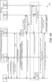
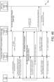
- FIGS 4A-4B depict a network procedure 400 for registering with the mobile communication network and establishing a control plane connection, according to embodiments of the disclosure.
- the network procedure 400 describes how an NWt CP connection is established between the UE and TNGF, during the 5GC registration procedure.
- the NWt CP connection may be created when the 5GC requests from TNGF to establish a UE context and provides the TNGF key (e.g., when the AMF sends message 10a).
- the network procedure 400 involves the UE 205, the TNAN 305 (including a TNAP 210 and a TNGF 215), and the 5GC 310 (an AMF 142 and AUSF 148 are shown in the 5GC 310, other NFs in the 5GC 310 are not shown for ease of illustration).
- the network procedure 400 begins.
- step 1 a layer-2 connection is established between the UE and the TNAP.
- this step corresponds to an 802.11 Association.
- this step corresponds to a PPP LCP negotiation. Note that in other types of non-3GPP access (e.g. Ethernet), this step may not be required.
- an EAP authentication procedure is initiated.
- the EAP messages are encapsulated into layer-2 packets, e.g. into IEEE 802.3/802.1x packets, into IEEE 802.11/802.1x packets, into PPP packets, etc.
- the UE 205 provides a special NAI that triggers the TNAP 210 to send an AAA request to a TNGF-CP, which operates as an AAA proxy. Between the TNAP 210 and TNGF-CP the EAP packets are encapsulated into AAA messages.
- an EAP-5G procedure is executed wherein the UE 205 registers with the 5GC 310.
- the UE does not receive an EAP-Request/5G-Start packet, then the UE determines that the non-3GPP access network does not support registration to 5GC. Then, it is up to the UE implementation to continue or stop the access authentication procedure.
- step 5 the UE 205 sends a NAS Registration Request message.
- steps 6 the TNGF 215 forwards the NAS Registration Request after selecting an AMF (here, the AMF 142).
- steps 8 the UE 205 is authenticated with the 5GC 310. Note that the UE 205 creates a TNGF key after successful authentication and also derives a TNAP key from the TNGF key. The TNGF key is also created in the AMF 142 after the successful authentication.
- step 9b the UE 205 receives the "TNGF Contact Info" which includes the MAC address of the TNGF 215 to which NAS signaling should be sent.
- the "TNGF Contact Info” may be retrieved by the UE 205 after step 11, e.g. via DHCP.
- the common TNAP key is used by the UE 205 and TNAP 210 to establish a security association to protect all subsequent traffic.
- the TNAP key is used as an 802.11 Pairwise Master Key (PMK) and a 4-way handshake is executed, which establishes a security association between the WLAN AP (e.g., an implementation of the TNAP 210) and the UE 205 that is used to protect unicast and multicast traffic over the air.
- PMK Pairwise Master Key
- step 12a after security is established between the UE 205 and TNAP 210, the TNAP 210 initiates the establishment of a point-to-point CP connection with the TNGF 215.
- the TNGF 215 assigns to this connection a VLAN Id (e.g., VLAN-0) and specific QoS parameters (e.g., a DSCP value).
- VLAN Id e.g., VLAN-0
- QoS parameters e.g., a DSCP value
- the TNGF 215 sends an NWt Connection Setup Request message to the UE 205.
- This message indicates to the UE 205 that a new NWt CP connection with the TNGF 215 is requested, which is assigned a certain VLAN Id (e.g., VLAN-0) and QoS parameters.
- VLAN Id e.g., VLAN-0
- QoS parameters e.g., QoS parameters.
- the UE 205 may reserve access-specific resources for the NWt CP connection based on the received QoS parameters.
- the UE 205 responds with a NWt Connection Setup Response message.
- the TNGF 215 sends an N2 Initial Context Setup Response informing the AMF 142 that a UE context and a signaling connection (i.e. a NWt CP connection) with the UE 205 have been created.
- the TNGF 215 receives a NAS Registration Accept message.
- This Ethernet frame is forwarded to the TNAP 210 via the established point-to-point CP connection, which is associated with VLAN-0 and then from TNAP 210 to UE 205.
- the TNAN 210 may assign to the UE 205 (e.g. with DHCP) local IP configuration data, which can be used for non-seamless offload traffic. Note that the UE 205 sends the non-seamless offload traffic with EtherType other than "5G-NWt", so this traffic is not forwarded to TNGF 215.
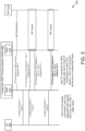
- FIGS 5A-5B depict a network procedure 500 for establishing user plane connections, according to embodiments of the disclosure.
- the network procedure 500 specifies how one or more NWt UP connections are created between the UE and TNGF, during the establishment of a PDU session.
- the network procedure 500 involves the UE 205, the TNAN 305 (including a TNAP 210 and a TNGF 215), and the 5GC 310 (including an AMF 142, other NFs in the 5GC 310 are not shown for ease of illustration).
- the network procedure 500 begins.
- step 1 over the established NWt CP connection the UE 205 sends to the TNGF 215 an NWt UL NAS Transport message, which encapsulates a NAS PDU Session Establishment Request.
- This NAS message is forwarded to the AMF 142.
- step 2 the 5GC 310 accepts the PDU session request and decides to use two QoS flows for transferring the traffic of the PDU session. Therefore, the NGAP message sent to TNGF 215 includes two QoS Flow Identifiers (QFIs) and the QoS parameters for each one (including 5QI, ARP, etc.).
- the TNGF 215 decides to establish a dedicated NWt UP connection for each QoS flow.
- the TNGF 215 initiates the establishment an NWt UP connection for the first QoS flow.
- a NWt UP connection is similar to a Data Radio Bearer, but, instead of being identified with a radio bearer id, it is identified with a VLAN Id.
- the TNGF 215 assigns VLAN-1 to the NWt UP connection, it establishes a point-to-point UP connection with the TNAP 210 using the QoS params-1, and sends a NWt Establish UP Connection Request to the UE 205 via the established NWt CP connection.
- This request informs the UE 205 that a new NWt UP connection is established, which is associated with PDU session ID-1, QFI-1, QoS params-1 and VLAN-1.
- the UE 205 may reserve access-specific resources for this NWt UP connections (based on QoS params-1) and the UE 205 responds to the TNGF 215.
- step 4 an NWt UP connection for the second QoS flow is established using similar techniques as in step 3. This second NWt UP connection is assigned VLAN-2.
- step 5 over the established NWt CP connection, the TNGF 215 sends to UE 205 an NWt DL NAS Transport message, which encapsulates the NAS PDU Session Establishment Accept (e.g., received in step 2).
- step 6 the TNGF 215 informs the AMF 142 that the necessary access resources for the PDU session have been set up.
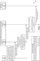
- Figure 6 depicts a network procedure 600 for forwarding a NAS message from the UE to the AMF using a control plane connection, according to embodiments of the disclosure. Similar operation is conducted in the opposite direction (e.g., to send a NAS message from the AMF to the UE).
- the network procedure 600 involves the UE 205, the TNAN 305 (including a TNAP 210 and a TNGF 215), and the 5GC 310 (including the AMF 142, other NFs in the 5GC 310 are not shown for ease of illustration).
- the network procedure 600 begins and the UE 205 determines to send a NAS message to 5GC 310.
- the destination MAC is set to the MAC address of the TNGF 215, the source MAC is set to the MAC address of the UE 205, and the NWt header indicates the NWt payload contains a NAS message.
- the VLAN ID 0 in turn is mapped to an appropriate 802.11 TC.
- the TNAP 210 After verifying the integrity and the origin of the Ethernet/802.11 frame, the TNAP 210 forwards the Ethernet/802.11 frame to the TNGF 215 via the point-to-point connection associated with VLAN ID 0.
- the TNGF 215 receives the NWt message, extracts the NAS message, and forwards the NAS message to the AMF 142 via the corresponding N2 connection.
- Figure 7 depicts a network procedure 700 for forwarding PDU Session data from the UE to the UPF using a user plane connection, according to embodiments of the disclosure. Similar operation is conducted in the opposite direction (e.g., to send a PDU Session data from the UPF to the UE).
- the network procedure 700 involves the UE 205, the TNAN 305 (including a TNAP 210 and a TNGF 215), and the 5GC 310 (including the UPF 141, other NFs in the 5GC 310 are not shown for ease of illustration).
- the network procedure 700 begins and the UE 205 determines to send PDU Session data.
- the destination MAC is set to the MAC address of the TNGF 215, the source MAC is set to the MAC address of the UE 205, and the NWt header includes the QFI for the PDU Session data and indicates that the NWt payload contains PDU Session data.
- the VLAN ID 2 in turn is mapped to an appropriate 802.11 TC.
- the TNAP 210 After verifying the integrity and the origin of the Ethernet/802.11 frame, the TNAP 210 forwards the Ethernet/802.11 frame to the TNGF 215 via the point-to-point connection associated with VLAN ID 2.
- the TNGF 215 receives the NWt message, extracts the PDU Session data, and forwards the PDU Session data to the UPF 141 via the corresponding N3 connection.
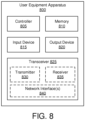
- Figure 8 depicts one embodiment of a user equipment apparatus 800 that may be used for establishing network connections via a trusted gateway function, according to embodiments of the disclosure.
- the user equipment apparatus 800 may be one embodiment of the remote unit 105.
- the user equipment apparatus 800 may include a processor 805, a memory 810, an input device 815, an output device 820, a transceiver 825.
- the input device 815 and the output device 820 are combined into a single device, such as a touch screen.
- the user equipment apparatus 800 does not include any input device 815 and/or output device 820.
- the transceiver 825 includes at least one transmitter 830 and at least one receiver 835. Additionally, the transceiver 825 may support at least one network interface 840. Here, the at least one network interface 840 facilitates communication with a TNAP and TNGF. Additionally, the at least one network interface 840 may include an interface used for communications with an eNB or gNB (e.g., using the "Uu" interface)an UPF, an SMF, and/or an AMF.
- an eNB or gNB e.g., using the "Uu" interface
- the processor 805, in one embodiment, may include any known controller capable of executing computer-readable instructions and/or capable of performing logical operations.
- the processor 805 may be a microcontroller, a microprocessor, a central processing unit (“CPU"), a graphics processing unit (“GPU”), an auxiliary processing unit, a field programmable gate array (“FPGA”), or similar programmable controller.
- the processor 805 executes instructions stored in the memory 810 to perform the methods and routines described herein.
- the processor 805 is communicatively coupled to the memory 810, the input device 815, the output device 820, the first transceiver 825, and the second transceiver 830.
- the processor 805 communicates a first set of messages of a first type (e.g., NAS messages) with a mobile communication network via a non-3GPP access network.
- a first encapsulation protocol e.g., NAS messages encapsulated in the EAP protocol
- the first set of messages of the first type initiate a registration procedure to the mobile communication network via the non-3GPP access network.
- the processor 805 receives a connection setup request via the non-3GPP access network and communicates subsequent messages of the first type with the mobile communication network via the non-3GPP access network.
- the connection setup request contains information for activating a second encapsulation protocol (e.g., NWt protocol encapsulation) such that the subsequent messages of the first type are encapsulated with the second encapsulation protocol.
- NWt protocol encapsulation e.g., NWt protocol encapsulation
- the subsequent messages of the first type complete the registration procedure.
- the processor 805 further creates a first security key using the first set of messages of the first type and establishes a security association with the non-3GPP access network.
- the security association uses a second security key derived from the first security key.
- the connection setup request is received via the non-3GPP access network in response to establishing a security association with the non-3GPP access network.
- the processor 805 further establishes a CP connection using a first VLAN identifier.
- the CP connection is established by the connection setup request, which also contains the first VLAN identifier.
- messages on the CP connection are encapsulated with the second encapsulation protocol.
- the processor 805 further sends a request to establish a PDU session from the remote unit and receives one or more messages via the CP connection, each message requesting the establishment of a UP connection.
- messages on the UP connection(s) are encapsulated with the second encapsulation protocol.
- each of the one or more UP connections is associated with a different VLAN identifier.
- the VLAN identifiers associated with the one or more UP connections is different than a first VLAN identifier associated with a CP connection.
- each of the one or more UP connections may be associated with a different set of one or more quality of service flow identifier.
- the processor 805 establishes a CP connection (e.g., NWt CP connection) with a non-3GPP access network node during a registration procedure with a mobile communication system via a non-3GPP access network (e.g., the TNAN 305).
- a CP connection e.g., NWt CP connection
- messages on the CP connection are encapsulated with a first encapsulation protocol (e.g., NAS messages encapsulated in the NWt encapsulation).
- the processor 805 controls the transceiver 825 to send a request to establish a data connection with the mobile communication network (e.g., sends a PDU Session Establishment request).
- the request is sent via the CP connection.
- the processor 805 establishes a plurality of UP connections with the access network node in response to the mobile communication network accepting the request.
- messages on each of the plurality of UP connections are encapsulated with the first encapsulation protocol (e.g., PDU session data are encapsulated within NWt packets).
- the control plane connection is associated with a first virtual local area network ("VLAN") and each of the plurality of user plane connections is associated with a different VLAN identifier, wherein the first VLAN identifier (associated with the control place connection) is different than the VLAN identifiers associated with the UP connections.
- VLAN virtual local area network
- the requested data connection may comprise multiple QoS flows (e.g., mapped to different QFIs).
- different ones of the multiple QoS flows are mapped to different ones of the plurality of UP connections.
- a single UP connection is associated with multiple QoS flows, where a single QoS flow is not associated with multiple UP connections.
- the memory 810 in one embodiment, is a computer readable storage medium.
- the memory 810 includes volatile computer storage media.
- the memory 810 may include a RAM, including dynamic RAM (“DRAM”), synchronous dynamic RAM (“SDRAM”), and/or static RAM (“SRAM”).
- the memory 810 includes non-volatile computer storage media.
- the memory 810 may include a hard disk drive, a flash memory, or any other suitable non-volatile computer storage device.
- the memory 810 includes both volatile and non-volatile computer storage media.
- the memory 810 stores data relating to establishing network connections via a trusted gateway function, for example storing control plane connection contexts, user plane connection contexts, VLAN identifiers, correlation between connections and VLAN identifiers, and the like.
- the memory 810 also stores program code and related data, such as an operating system ("OS”) or other controller algorithms operating on the user equipment apparatus 800 and one or more software applications.
- OS operating system
- the input device 815 may include any known computer input device including a touch panel, a button, a keyboard, a stylus, a microphone, or the like.
- the input device 815 may be integrated with the output device 820, for example, as a touchscreen or similar touch-sensitive display.
- the input device 815 includes a touchscreen such that text may be input using a virtual keyboard displayed on the touchscreen and/or by handwriting on the touchscreen.
- the input device 815 includes two or more different devices, such as a keyboard and a touch panel.
- the transceiver 825 communicates with one or more network functions of a mobile communication network via one or more access networks.
- the transceiver 825 operates under the control of the processor 805 to transmit messages, data, and other signals and also to receive messages, data, and other signals.
- the processor 805 may selectively activate the transceiver (or portions thereof) at particular times in order to send and receive messages.
- the transceiver 825 may include one or more transmitters 830 and one or more receivers 835. In certain embodiments, the one or more transmitters 830 and/or the one or more receivers 835 may share transceiver hardware and/or circuitry.
- the one or more transmitters 830 and/or the one or more receivers 835 may share antenna(s), antenna tuner(s), amplifier(s), filter(s), oscillator(s), mixer(s), modulator/demodulator(s), power supply, and the like.
- the transceiver 825 is configured to communication with 8GPP access network(s) 120 and the non-3GPP access network(s) 130. In some embodiments, the transceiver 825 implements modem functionality for the 8GPP access network(s) 120 and/or the non-3GPP access network(s) 130. In one embodiment, the transceiver 825 implements multiple logical transceivers using different communication protocols or protocol stacks, while using common physical hardware.
- the processor 905, in one embodiment, may include any known controller capable of executing computer-readable instructions and/or capable of performing logical operations.
- the processor 905 may be a microcontroller, a microprocessor, a central processing unit ("CPU"), a graphics processing unit (“GPU”), an auxiliary processing unit, a field programmable gate array (“FPGA”), or similar programmable controller.
- the processor 905 executes instructions stored in the memory 910 to perform the methods and routines described herein.
- the processor 905 is communicatively coupled to the memory 910, the input device 915, the output device 920, and the transceiver 925.
- the processor 905 relays a first set of messages of a first type (e.g., NAS messages) between a remote unit and a mobile communication network via a non-3GPP access network.
- a first type e.g., NAS messages
- the first set of messages of the first type are encapsulated with a first encapsulation protocol (e.g., NAS messages encapsulated in the EAP protocol).
- the first set of messages of the first type initiate a registration procedure to the mobile communication network via the non-3GPP access network.
- the processor 905 sends a connection setup request to the remote unit via the non-3GPP access network.
- the connection setup request contains information for activating a second encapsulation protocol (e.g., NWt encapsulation).
- sending a connection setup request includes sending a request to establish a CP connection using a first VLAN identifier.
- messages over the CP connection are encapsulated with the second encapsulation protocol.
- the processor 905 relays subsequent messages of the first type between the remote unit and the mobile communication network via the non-3GPP access network.
- the subsequent messages of the first type are encapsulated with the second encapsulation protocol (e.g., NAS encapsulated in the NWt encapsulation).
- the subsequent messages of the first type complete the registration procedure.
- the processor 905 establishes a CP connection with a remote unit over a non-3GPP access network during a registration procedure of the remote unit to a mobile communication network.
- messages on the CP connection are encapsulated with a first encapsulation protocol (e.g., NAS messages are encapsulated within NWt packets).
- the processor 905 controls the transceiver 925 to forward a request from the remote unit to establish a data connection (e.g., PDU Session) with the mobile communication network.
- a data connection e.g., PDU Session
- the request e.g., PDU Session Establishment request
- the request is received via the CP connection.
- the processor 905 establishes a plurality of UP connections with the remote unit in response to the mobile communication network accepting the request, wherein messages on each of the plurality of UP connections are encapsulated with the first encapsulation protocol (e.g., PDU session data are encapsulated within NWt packets).
- the control plane connection is associated with a first virtual local area network ("VLAN") and each of the plurality of user plane connections is associated with a different VLAN identifier, wherein the first VLAN identifier is different than the VLAN identifiers associated with the UP connections.
- VLAN virtual local area network
- the data connection (e.g., PDU Session) comprises multiple QoS flows, wherein different ones of the multiple QoS flows are mapped to different ones of the plurality of UP connections.
- a single UP connection is associated with multiple QoS flows, where a single QoS flow is not associated with multiple UP connections.
- the memory 910 stores data relating to establishing network connections via a trusted gateway function, for example storing control plane connection contexts, user plane connection contexts, VLAN identifiers, correlation between connections and VLAN identifiers, and the like.
- the memory 910 also stores program code and related data, such as an operating system ("OS") or other controller algorithms operating on the network equipment apparatus 900 and one or more software applications.
- OS operating system
- the output device 920 may include any known electronically controllable display or display device.
- the output device 920 may be designed to output visual, audible, and/or haptic signals.
- the output device 920 includes an electronic display capable of outputting visual data to a user.
- the output device 920 may include, but is not limited to, an LCD display, an LED display, an OLED display, a projector, or similar display device capable of outputting images, text, or the like to a user.
- the output device 920 may include a wearable display such as a smart watch, smart glasses, a heads-up display, or the like.
- the output device 920 may be a component of a smart phone, a personal digital assistant, a television, a table computer, a notebook (laptop) computer, a personal computer, a vehicle dashboard, or the like.
- the output device 920 includes one or more speakers for producing sound.
- the output device 920 may produce an audible alert or notification (e.g., a beep or chime).
- the output device 920 includes one or more haptic devices for producing vibrations, motion, or other haptic feedback.
- all or portions of the output device 920 may be integrated with the input device 915.
- the input device 915 and output device 920 may form a touchscreen or similar touch-sensitive display. In other embodiments, all or portions of the output device 920 may be located near the input device 915.
- the transceiver 925 communicates with one or more access network nodes and/or with one or more network functions of a mobile communication network.
- the transceiver 925 operates under the control of the processor 905 to transmit messages, data, and other signals and also to receive messages, data, and other signals.
- the processor 905 may selectively activate the transceiver (or portions thereof) at particular times in order to send and receive messages.
- the transceiver 925 may include one or more transmitters 930 and one or more receivers 935.
- the transceiver 925 may support one or more the network interface 940 for communicating with network functions in a mobile core network.
- Figure 10 depicts a method 1000 for establishing network connections via a trusted gateway function, according to embodiments of the disclosure.
- the method 1000 is performed by an apparatus, such as the TNGF 135, the TNGF 215, and/or the network equipment apparatus 900.
- the method 1000 may be performed by a processor executing program code, for example, a microcontroller, a microprocessor, a CPU, a GPU, an auxiliary processing unit, a FPGA, or the like.
- the method 1000 begins and relays 1005 a first set of messages of a first type between a remote unit and a mobile communication network via a non-3GPP access network.
- the first set of messages of the first type are encapsulated with a first encapsulation protocol.
- the first set of messages of the first type initiate a registration procedure to the mobile communication network via the non-3GPP access network.
- the method 1000 includes sending 1010 a connection setup request to the remote unit via the non-3GPP access network.
- the connection setup request contains information for activating a second encapsulation protocol.
- Figure 11 depicts a method 1100 for establishing network connections via a trusted gateway function, according to embodiments of the disclosure.
- the method 1100 is performed by an apparatus, such as the TNGF 135, the TNGF 215, and/or the network equipment apparatus 900.
- the method 1100 may be performed by a processor executing program code, for example, a microcontroller, a microprocessor, a CPU, a GPU, an auxiliary processing unit, a FPGA, or the like.
- the method 1100 begins and establishes 1105 a control plane connection with a remote unit over a non-3GPP access network during a registration procedure of the remote unit to a mobile communication network.
- messages on the control plane connection are encapsulated with a first encapsulation protocol.
- the method 1100 includes forwarding 1110 a request from the remote unit to establish a data connection with the mobile communication network.
- the request is received via the control plane connection.
- the method 1100 includes establishing 1115 a plurality of user plane connections with the remote unit in response to the mobile communication network accepting the request.
- messages on each of the plurality of user plane connections are encapsulated with the first encapsulation protocol.
- the method 1100 ends.
- the control plane connection is associated with a first VLAN identifier and each of the plurality of user plane connections is associated with a different VLAN identifier, wherein the first VLAN identifier is different than the VLAN identifiers associated with the user plane connections.
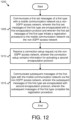
- Figure 12 depicts a method 1200 for establishing network connections via a trusted gateway function, according to embodiments of the disclosure.
- the method 1200 is performed by an apparatus, such as the remote unit 125, the UE 205, and/or the user equipment apparatus 800.
- the method 1200 may be performed by a processor executing program code, for example, a microcontroller, a microprocessor, a CPU, a GPU, an auxiliary processing unit, a FPGA, or the like.
- the method 1200 begins and communicates 1205 a first set of messages of a first type with a mobile communication network via a non-3GPP access network.
- the first set of messages of the first type are encapsulated with a first encapsulation protocol.
- the first set of messages of the first type initiate a registration procedure to the mobile communication network via the non-3GPP access network.
- the method 1200 includes receiving 1210 a connection setup request via the non-3GPP access network.
- the connection setup request contains information for activating a second encapsulation protocol.
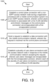
- Figure 13 depicts a method 1300 for establishing network connections via a trusted gateway function, according to embodiments of the disclosure.
- the method 1300 is performed by an apparatus, such as the remote unit 125, the UE 205, and/or the user equipment apparatus 800.
- the method 1300 may be performed by a processor executing program code, for example, a microcontroller, a microprocessor, a CPU, a GPU, an auxiliary processing unit, a FPGA, or the like.
- the method 1300 begins and establishes 1305 a control plane connection with a non-3GPP access network node during a registration procedure with a mobile communication system via a non-3GPP access network.
- messages on the control plane connection are encapsulated with a first encapsulation protocol.
- the method 1300 includes sending 1310 a request to establish a data connection with the mobile communication network.
- the request is sent via the control plane connection.
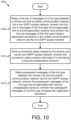
- the first method includes relaying a first set of messages of a first type between a remote unit and a mobile communication network via a non-3GPP access network, wherein the first set of messages of the first type are encapsulated with a first encapsulation protocol and wherein the first set of messages of the first type initiate a registration procedure to the mobile communication network via the non-3GPP access network.
- the first method includes sending a connection setup request to the remote unit via the non-3GPP access network, wherein the connection setup request contains information for activating a second encapsulation protocol.
- the first method also includes relaying subsequent messages of the first type between the remote unit and the mobile communication network via the non-3GPP access network, wherein the subsequent messages of the first type are encapsulated with the second encapsulation protocol, wherein the subsequent messages of the first type complete the registration procedure.
- the subsequent messages of the first type encapsulated with the second encapsulation protocol are marked with a specific EtherType and a VLAN identifier.
- the first method further includes: receiving a first security key from the mobile communication network, deriving a second security key from the first security key, and forwarding the second security key to the non-3GPP access network.
- the first method may further include receiving an indication that a security association has been established for the remote unit in the non-3GPP access network, wherein the security association uses the second security key. Additionally, the connection setup may be protected by the security association.
- sending a connection setup request comprises sending a request to establish a control plane connection using a first VLAN identifier, wherein messages over the control plane connection are encapsulated with the second encapsulation protocol.
- the first method further includes: receiving a request to establish a PDU session from the mobile communication network and establishing one or more user plane connections with the remote unit in response to receiving the request to establish a PDU session, wherein messages on the one or more user plane connections are encapsulated with the second encapsulation protocol.
- each of the one or more user plane connections may be associated with a different VLAN identifier.
- the VLAN identifiers associated with the one or more user plane connections is different than a first VLAN identifier associated with a control plane connection.
- each of the one or more user plane connections may be associated with a different set of one or more quality of service flow identifiers.
- the second method includes establishing a control plane connection with a remote unit over a non-3GPP access network during a registration procedure of the remote unit to a mobile communication network, wherein messages on the control plane connection are encapsulated with a first encapsulation protocol.
- the second method includes forwarding a request from the remote unit to establish a data connection with the mobile communication network, wherein the request is received via the control plane connection.
- the second method also includes establishing a plurality of user plane connections with the remote unit in response to the mobile communication network accepting the request, wherein messages on each of the plurality of user plane connections are encapsulated with the first encapsulation protocol.
- the data connection comprises multiple quality of service QoS flows, wherein different ones of the multiple QoS flows are mapped to different ones of the plurality of user plane connections.
- the control plane connection is associated with a first VLAN and each of the plurality of user plane connections is associated with a different VLAN identifier, wherein the first VLAN identifier is different than the VLAN identifiers associated with the user plane connections.
- the third method includes communicating a first set of messages of a first type with a mobile communication network via a non-3GPP access network, wherein the first set of messages of the first type are encapsulated with a first encapsulation protocol and wherein the first set of messages of the first type initiate a registration procedure to the mobile communication network via the non-3GPP access network.
- the third method includes receiving a connection setup request via the non-3GPP access network, wherein the connection setup request contains information for activating a second encapsulation protocol.
- the third method also includes communicating subsequent messages of the first type with the mobile communication network via the non-3GPP access network, wherein the subsequent messages of the first type are encapsulated with the second encapsulation protocol, wherein the subsequent messages of the first type complete the registration procedure.
- the subsequent messages of the first type encapsulated with the second encapsulation protocol are marked with a specific EtherType and a VLAN identifier
- the third method further includes: creating a first security key using the first set of messages of the first type and establishing a security association with the non-3GPP access network.
- the security association uses a second security key derived from the first security key.
- the received via the non-3GPP access network in response to establishing a security association with the non-3GPP access network.
- the third method further includes: establishing a control plane connection using a first VLAN identifier, wherein the control plane connection is established by the connection setup request that contains the first VLAN identifier and wherein messages on the control plane connection are encapsulated with the second encapsulation protocol.
- the third method further includes: sending a request to establish a PDU session from the remote unit; and receiving one or more messages via the control plane connection, each message requesting the establishment of a user plane connection.
- messages on a user plane connection are encapsulated with the second encapsulation protocol.
- each of the one or more user plane connections is associated with a different VLAN identifier.
- the VLAN identifiers associated with the one or more user plane connections is different than a first VLAN identifier associated with a control plane connection.
- each of the one or more user plane connections may be associated with a different set of one or more quality of service flow identifier.
- the data connection comprises multiple QoS flows, wherein different ones of the multiple QoS flows are mapped to different ones of the plurality of user plane connections.
- the control plane connection is associated with a first VLAN and each of the plurality of user plane connections is associated with a different VLAN identifier, wherein the first VLAN identifier is different than the VLAN identifiers associated with the user plane connections.
Claims (15)
- Procédé exécuté par une entité de réseau, le procédé comprenant :le relais (1005) d'un premier ensemble de messages d'un premier type entre une unité distante et un réseau de communication mobile par l'intermédiaire d'un réseau d'accès non 3GPP, dans lequel le premier ensemble de messages du premier type est encapsulé avec un premier protocole d'encapsulation et dans lequel le premier ensemble de messages du premier type initie une procédure d'enregistrement auprès du réseau de communication mobile par l'intermédiaire du réseau d'accès non 3GPP ;l'envoi (1010) d'une demande d'établissement de connexion à l'unité distante par l'intermédiaire du réseau d'accès non 3GPP, dans lequel la demande d'établissement de connexion contient des informations pour activer un second protocole d'encapsulation ; et le relais (1015) de messages suivants du premier type entre l'unité distante et le réseau de communication mobile par l'intermédiaire du réseau d'accès non 3GPP, dans lequel les messages suivants du premier type sont encapsulés avec le second protocole d'encapsulation, dans lequel les messages suivants du premier type terminent la procédure d'enregistrement.
- Procédé selon la revendication 1, dans lequel les messages suivants du premier type encapsulés avec le second protocole d'encapsulation sont marqués avec un EtherType spécifique et un identificateur de réseau local virtuel, VLAN.
- Procédé selon la revendication 1, comprenant en outre :
la réception d'une première clé de sécurité à partir du réseau de communication mobile ; la dérivation d'une seconde clé de sécurité à partir de la première clé de sécurité ; et la transmission de la seconde clé de sécurité au réseau d'accès non 3GPP. - Procédé selon la revendication 3, comprenant en outre la réception d'une indication selon laquelle une association de sécurité a été établie pour l'unité distante dans le réseau d'accès non 3GPP, dans lequel l'association de sécurité utilise la seconde clé de sécurité.
- Procédé selon la revendication 4, dans lequel la demande d'établissement de connexion est envoyée à l'unité distante par l'intermédiaire du réseau d'accès non 3GPP en réponse à la réception de l'indication selon laquelle l'association de sécurité a été établie pour l'unité distante dans le réseau d'accès non 3GPP.
- Procédé selon la revendication 1, dans lequel l'envoi de la demande d'établissement de connexion comprend l'envoi d'une demande pour établir une connexion de plan de commande à l'aide d'un premier identificateur de réseau local virtuel, VLAN, dans lequel des messages sur la connexion de plan de commande sont encapsulés avec le second protocole d'encapsulation.
- Procédé selon la revendication 1, comprenant en outre : la réception d'une demande pour établir une session d'unité de données de protocole, PDU, à partir du réseau de communication mobile ; et l'établissement d'une ou plusieurs connexions de plan utilisateur avec l'unité distante en réponse à la réception de la demande d'établissement de la session PDU, dans lequel les messages sur la ou les connexions de plan utilisateur sont encapsulés avec le second protocole d'encapsulation.
- Procédé selon la revendication 7, dans lequel chacune de la ou des connexions de plan utilisateur est associée à un identificateur de réseau local virtuel, VLAN, différent, et facultativement dans lequel les identificateurs VLAN associés à la ou aux connexions de plan utilisateur sont différents d'un premier identificateur VLAN associé à une connexion de plan de commande.
- Procédé selon la revendication 7, dans lequel chacune de la ou des connexions de plan utilisateur est associée à un ensemble différent d'un ou plusieurs identificateurs de flux de qualité de service.
- Procédé exécuté par un appareil d'équipement utilisateur (800), le procédé comprenant :la communication (1205) d'un premier ensemble de messages d'un premier type avec un réseau de communication mobile par l'intermédiaire d'un réseau d'accès non 3GPP, dans lequel le premier ensemble de messages du premier type est encapsulé avec un premier protocole d'encapsulation et dans lequel le premier ensemble de messages du premier type initie une procédure d'enregistrement auprès du réseau de communication mobile par l'intermédiaire du réseau d'accès non 3GPP ;la réception (1210) d'une demande d'établissement de connexion par l'intermédiaire du réseau d'accès non 3GPP, dans lequel la demande d'établissement de connexion contient des informations pour activer un second protocole d'encapsulation ;et la communication (1215) de messages suivants du premier type avec le réseau de communication mobile par l'intermédiaire du réseau d'accès non 3GPP, dans lequel les messages suivants du premier type sont encapsulés avec le second protocole d'encapsulation, dans lequel les messages suivants du premier type terminent la procédure d'enregistrement.
- Procédé selon la revendication 10, dans lequel les messages suivants du premier type encapsulés avec le second protocole d'encapsulation sont marqués avec un EtherType spécifique et un identificateur de réseau local virtuel, VLAN.
- Procédé selon la revendication 10, comprenant en outre :
la création d'une première clé de sécurité à l'aide du premier ensemble de messages du premier type ; et l'établissement d'une association de sécurité avec le réseau d'accès non 3GPP, dans lequel l'association de sécurité utilise une seconde clé de sécurité dérivée de la première clé de sécurité. - Procédé selon la revendication 12, dans lequel la demande d'établissement de connexion est reçue par l'intermédiaire du réseau d'accès non 3GPP en réponse à l'établissement de l'association de sécurité avec le réseau d'accès non 3GPP.
- Procédé selon la revendication 10, comprenant en outre l'établissement d'une connexion de plan de commande à l'aide d'un premier identificateur de réseau local virtuel, VLAN, dans lequel la connexion de plan de commande est établie par la demande d'établissement de connexion qui contient le premier identificateur VLAN et dans lequel des messages sur la connexion de plan de commande sont encapsulés avec le second protocole d'encapsulation.
- Procédé selon la revendication 10, comprenant en outre :l'envoi d'une demande d'établissement d'une session d'unité de données de protocole, PDU ;et la réception d'un ou plusieurs messages par l'intermédiaire de la connexion de plan de commande, chaque message demandant l'établissement de la connexion de plan utilisateur, dans lequel des messages sur une connexion de plan utilisateur sont encapsulés avec le second protocole d'encapsulation.
Priority Applications (1)
| Application Number | Priority Date | Filing Date | Title |
|---|---|---|---|
| EP23191765.9A EP4250792A3 (fr) | 2018-09-27 | 2018-09-27 | Accès à un réseau 5g par l'intermédiaire d'un réseau d'accès non 3gpp |
Applications Claiming Priority (1)
| Application Number | Priority Date | Filing Date | Title |
|---|---|---|---|
| PCT/EP2018/076246 WO2020064107A1 (fr) | 2018-09-27 | 2018-09-27 | Accès à un réseau 5g via un réseau d'accès non 3gg |
Related Child Applications (2)
| Application Number | Title | Priority Date | Filing Date |
|---|---|---|---|
| EP23191765.9A Division EP4250792A3 (fr) | 2018-09-27 | 2018-09-27 | Accès à un réseau 5g par l'intermédiaire d'un réseau d'accès non 3gpp |
| EP23191765.9A Division-Into EP4250792A3 (fr) | 2018-09-27 | 2018-09-27 | Accès à un réseau 5g par l'intermédiaire d'un réseau d'accès non 3gpp |
Publications (3)
| Publication Number | Publication Date |
|---|---|
| EP3858083A1 EP3858083A1 (fr) | 2021-08-04 |
| EP3858083C0 EP3858083C0 (fr) | 2023-11-01 |
| EP3858083B1 true EP3858083B1 (fr) | 2023-11-01 |
Family
ID=63713869
Family Applications (2)
| Application Number | Title | Priority Date | Filing Date |
|---|---|---|---|
| EP23191765.9A Pending EP4250792A3 (fr) | 2018-09-27 | 2018-09-27 | Accès à un réseau 5g par l'intermédiaire d'un réseau d'accès non 3gpp |
| EP18779636.2A Active EP3858083B1 (fr) | 2018-09-27 | 2018-09-27 | Accès à un réseau 5g via un réseau d'accès non 3gpp |
Family Applications Before (1)
| Application Number | Title | Priority Date | Filing Date |
|---|---|---|---|
| EP23191765.9A Pending EP4250792A3 (fr) | 2018-09-27 | 2018-09-27 | Accès à un réseau 5g par l'intermédiaire d'un réseau d'accès non 3gpp |
Country Status (3)
| Country | Link |
|---|---|
| US (2) | US11683847B2 (fr) |
| EP (2) | EP4250792A3 (fr) |
| WO (1) | WO2020064107A1 (fr) |
Families Citing this family (5)
| Publication number | Priority date | Publication date | Assignee | Title |
|---|---|---|---|---|
| US11317318B2 (en) * | 2018-02-16 | 2022-04-26 | Nec Corporation | Distinguishing between general NAS level congestion and S-NSSAI related congestion control |
| CN111200878B (zh) * | 2018-11-19 | 2022-04-22 | 华为技术有限公司 | 信息传输方法及其装置 |
| US20220150694A1 (en) * | 2019-03-04 | 2022-05-12 | Telefonaktiebolaget Lm Ericsson (Publ) | Key derivation for non-3gpp access |
| BR112022020176A2 (pt) * | 2020-04-06 | 2022-11-22 | Lenovo Singapore Pte Ltd | Notificação em procedimento de eap |
| WO2021223862A1 (fr) * | 2020-05-06 | 2021-11-11 | Lenovo (Singapore) Pte. Ltd. | Réauthentification de fonction de passerelle |
Family Cites Families (7)
| Publication number | Priority date | Publication date | Assignee | Title |
|---|---|---|---|---|
| US8638749B2 (en) * | 2008-06-06 | 2014-01-28 | Qualcomm Incorporated | Method and apparatus for inter-network handoff |
| EP2923280B1 (fr) * | 2013-01-03 | 2018-04-04 | Huawei Technologies Co., Ltd. | Systèmes et méthodes d'accès à un réseau |
| WO2014107358A1 (fr) * | 2013-01-03 | 2014-07-10 | Intel Corporation | Connexions de données par paquets dans un système de communication sans fil utilisant un réseau local sans fil |
| WO2014204276A1 (fr) * | 2013-06-20 | 2014-12-24 | 삼성전자 주식회사 | Procédé et dispositif permettant de contrôler la qualité de service au sein d'un réseau lan sans fil |
| EP3523997A1 (fr) | 2016-10-05 | 2019-08-14 | Motorola Mobility LLC | Rattachement de réseau central par l'intermédiaire de réseaux d'accès non 3gpp autonomes |
| CN110603891B (zh) * | 2017-05-08 | 2023-11-21 | 摩托罗拉移动有限责任公司 | 向移动通信网络进行认证的方法 |
| SG11202012478QA (en) * | 2018-06-30 | 2021-01-28 | Nokia Solutions & Networks Oy | Handling failure of non-3gpp access to 5gcn not being allowed |
-
2018
- 2018-09-27 WO PCT/EP2018/076246 patent/WO2020064107A1/fr unknown
- 2018-09-27 EP EP23191765.9A patent/EP4250792A3/fr active Pending
- 2018-09-27 EP EP18779636.2A patent/EP3858083B1/fr active Active
- 2018-09-27 US US17/275,917 patent/US11683847B2/en active Active
-
2023
- 2023-05-01 US US18/310,456 patent/US20230269797A1/en active Pending
Also Published As
| Publication number | Publication date |
|---|---|
| EP3858083C0 (fr) | 2023-11-01 |
| US11683847B2 (en) | 2023-06-20 |
| EP3858083A1 (fr) | 2021-08-04 |
| EP4250792A2 (fr) | 2023-09-27 |
| WO2020064107A1 (fr) | 2020-04-02 |
| US20220039178A1 (en) | 2022-02-03 |
| US20230269797A1 (en) | 2023-08-24 |
| EP4250792A3 (fr) | 2023-11-15 |
Similar Documents
| Publication | Publication Date | Title |
|---|---|---|
| US11617067B2 (en) | Method to authenticate with a mobile communication network | |
| EP3881606B1 (fr) | Sélection de réseau d'accès pour un ue ne prenant pas en charge un nas sur un accès non-3gpp | |
| CN111406425B (zh) | 根据os特定的连接能力确定网络连接的类型 | |
| US10616095B2 (en) | Data flows over multiple access networks | |
| EP3858083B1 (fr) | Accès à un réseau 5g via un réseau d'accès non 3gpp | |
| US20220116327A1 (en) | Access traffic steering using a plurality of steering connections over different access networks | |
| US11277847B2 (en) | Establishing QOS flows over non-3GPP access | |
| US20240064514A1 (en) | Delegated data connection | |
| US11943135B2 (en) | Establishing a new QOS flow for a data connection | |
| US20220345887A1 (en) | Accessing a mobile communication network using a user identifier | |
| EP4128858B1 (fr) | Relocalisation d'une passerelle d'accès | |
| US20230156650A1 (en) | Relocating an access gateway |
Legal Events
| Date | Code | Title | Description |
|---|---|---|---|
| STAA | Information on the status of an ep patent application or granted ep patent |
Free format text: STATUS: UNKNOWN |
|
| STAA | Information on the status of an ep patent application or granted ep patent |
Free format text: STATUS: THE INTERNATIONAL PUBLICATION HAS BEEN MADE |
|
| PUAI | Public reference made under article 153(3) epc to a published international application that has entered the european phase |
Free format text: ORIGINAL CODE: 0009012 |
|
| STAA | Information on the status of an ep patent application or granted ep patent |
Free format text: STATUS: REQUEST FOR EXAMINATION WAS MADE |
|
| 17P | Request for examination filed |
Effective date: 20210217 |
|
| AK | Designated contracting states |
Kind code of ref document: A1 Designated state(s): AL AT BE BG CH CY CZ DE DK EE ES FI FR GB GR HR HU IE IS IT LI LT LU LV MC MK MT NL NO PL PT RO RS SE SI SK SM TR |
|
| DAV | Request for validation of the european patent (deleted) | ||
| DAX | Request for extension of the european patent (deleted) | ||
| REG | Reference to a national code |
Ref document number: 602018060440 Country of ref document: DE Ref country code: DE Ref legal event code: R079 Free format text: PREVIOUS MAIN CLASS: H04W0076100000 Ipc: H04W0076120000 |
|
| RIC1 | Information provided on ipc code assigned before grant |
Ipc: H04W 60/00 20090101ALN20230316BHEP Ipc: H04W 88/16 20090101ALN20230316BHEP Ipc: H04W 84/12 20090101ALN20230316BHEP Ipc: H04W 84/04 20090101ALN20230316BHEP Ipc: H04W 12/06 20210101ALI20230316BHEP Ipc: H04W 12/041 20210101ALI20230316BHEP Ipc: H04L 9/40 20220101ALI20230316BHEP Ipc: H04W 76/12 20180101AFI20230316BHEP |
|
| GRAP | Despatch of communication of intention to grant a patent |
Free format text: ORIGINAL CODE: EPIDOSNIGR1 |
|
| STAA | Information on the status of an ep patent application or granted ep patent |
Free format text: STATUS: GRANT OF PATENT IS INTENDED |
|
| RIC1 | Information provided on ipc code assigned before grant |
Ipc: H04W 60/00 20090101ALN20230323BHEP Ipc: H04W 88/16 20090101ALN20230323BHEP Ipc: H04W 84/12 20090101ALN20230323BHEP Ipc: H04W 84/04 20090101ALN20230323BHEP Ipc: H04W 12/06 20210101ALI20230323BHEP Ipc: H04W 12/041 20210101ALI20230323BHEP Ipc: H04L 9/40 20220101ALI20230323BHEP Ipc: H04W 76/12 20180101AFI20230323BHEP |
|
| RIC1 | Information provided on ipc code assigned before grant |
Ipc: H04W 60/00 20090101ALN20230406BHEP Ipc: H04W 88/16 20090101ALN20230406BHEP Ipc: H04W 84/12 20090101ALN20230406BHEP Ipc: H04W 84/04 20090101ALN20230406BHEP Ipc: H04W 12/06 20210101ALI20230406BHEP Ipc: H04W 12/041 20210101ALI20230406BHEP Ipc: H04L 9/40 20220101ALI20230406BHEP Ipc: H04W 76/12 20180101AFI20230406BHEP |
|
| INTG | Intention to grant announced |
Effective date: 20230426 |
|
| GRAS | Grant fee paid |
Free format text: ORIGINAL CODE: EPIDOSNIGR3 |
|
| GRAA | (expected) grant |
Free format text: ORIGINAL CODE: 0009210 |
|
| STAA | Information on the status of an ep patent application or granted ep patent |
Free format text: STATUS: THE PATENT HAS BEEN GRANTED |
|
| AK | Designated contracting states |
Kind code of ref document: B1 Designated state(s): AL AT BE BG CH CY CZ DE DK EE ES FI FR GB GR HR HU IE IS IT LI LT LU LV MC MK MT NL NO PL PT RO RS SE SI SK SM TR |
|
| REG | Reference to a national code |
Ref country code: GB Ref legal event code: FG4D |
|
| REG | Reference to a national code |
Ref country code: CH Ref legal event code: EP |
|
| REG | Reference to a national code |
Ref country code: DE Ref legal event code: R096 Ref document number: 602018060440 Country of ref document: DE |
|
| REG | Reference to a national code |
Ref country code: IE Ref legal event code: FG4D |
|
| U01 | Request for unitary effect filed |
Effective date: 20231128 |
|
| U07 | Unitary effect registered |
Designated state(s): AT BE BG DE DK EE FI FR IT LT LU LV MT NL PT SE SI Effective date: 20231204 |
|
| PG25 | Lapsed in a contracting state [announced via postgrant information from national office to epo] |
Ref country code: GR Free format text: LAPSE BECAUSE OF FAILURE TO SUBMIT A TRANSLATION OF THE DESCRIPTION OR TO PAY THE FEE WITHIN THE PRESCRIBED TIME-LIMIT Effective date: 20240202 |
|
| PG25 | Lapsed in a contracting state [announced via postgrant information from national office to epo] |
Ref country code: IS Free format text: LAPSE BECAUSE OF FAILURE TO SUBMIT A TRANSLATION OF THE DESCRIPTION OR TO PAY THE FEE WITHIN THE PRESCRIBED TIME-LIMIT Effective date: 20240301 |
|
| PG25 | Lapsed in a contracting state [announced via postgrant information from national office to epo] |
Ref country code: ES Free format text: LAPSE BECAUSE OF FAILURE TO SUBMIT A TRANSLATION OF THE DESCRIPTION OR TO PAY THE FEE WITHIN THE PRESCRIBED TIME-LIMIT Effective date: 20231101 |
|
| PG25 | Lapsed in a contracting state [announced via postgrant information from national office to epo] |
Ref country code: IS Free format text: LAPSE BECAUSE OF FAILURE TO SUBMIT A TRANSLATION OF THE DESCRIPTION OR TO PAY THE FEE WITHIN THE PRESCRIBED TIME-LIMIT Effective date: 20240301 Ref country code: GR Free format text: LAPSE BECAUSE OF FAILURE TO SUBMIT A TRANSLATION OF THE DESCRIPTION OR TO PAY THE FEE WITHIN THE PRESCRIBED TIME-LIMIT Effective date: 20240202 Ref country code: ES Free format text: LAPSE BECAUSE OF FAILURE TO SUBMIT A TRANSLATION OF THE DESCRIPTION OR TO PAY THE FEE WITHIN THE PRESCRIBED TIME-LIMIT Effective date: 20231101 |