EP3857944B1 - Verbesserungen für urllc-sps zum meistern von zeitdrifts zwischen einem drahtlosen netzwerk und einer benutzergeräteseitigen anwendung - Google Patents
Verbesserungen für urllc-sps zum meistern von zeitdrifts zwischen einem drahtlosen netzwerk und einer benutzergeräteseitigen anwendung Download PDFInfo
- Publication number
- EP3857944B1 EP3857944B1 EP19752725.2A EP19752725A EP3857944B1 EP 3857944 B1 EP3857944 B1 EP 3857944B1 EP 19752725 A EP19752725 A EP 19752725A EP 3857944 B1 EP3857944 B1 EP 3857944B1
- Authority
- EP
- European Patent Office
- Prior art keywords
- data packet
- configuration
- jitter
- scheduling
- active configuration
- Prior art date
- Legal status (The legal status is an assumption and is not a legal conclusion. Google has not performed a legal analysis and makes no representation as to the accuracy of the status listed.)
- Active
Links
Images





Classifications
-
- H—ELECTRICITY
- H04—ELECTRIC COMMUNICATION TECHNIQUE
- H04W—WIRELESS COMMUNICATION NETWORKS
- H04W24/00—Supervisory, monitoring or testing arrangements
- H04W24/08—Testing, supervising or monitoring using real traffic
-
- H—ELECTRICITY
- H04—ELECTRIC COMMUNICATION TECHNIQUE
- H04W—WIRELESS COMMUNICATION NETWORKS
- H04W56/00—Synchronisation arrangements
- H04W56/0035—Synchronisation arrangements detecting errors in frequency or phase
-
- H—ELECTRICITY
- H04—ELECTRIC COMMUNICATION TECHNIQUE
- H04W—WIRELESS COMMUNICATION NETWORKS
- H04W72/00—Local resource management
- H04W72/50—Allocation or scheduling criteria for wireless resources
- H04W72/54—Allocation or scheduling criteria for wireless resources based on quality criteria
-
- H—ELECTRICITY
- H04—ELECTRIC COMMUNICATION TECHNIQUE
- H04W—WIRELESS COMMUNICATION NETWORKS
- H04W88/00—Devices specially adapted for wireless communication networks, e.g. terminals, base stations or access point devices
- H04W88/02—Terminal devices
- H04W88/04—Terminal devices adapted for relaying to or from another terminal or user
Definitions
- the present document refers to wireless communications (e.g., between a user equipment, UE, and a base station, BS, which may be a gNB).
- wireless communications e.g., between a user equipment, UE, and a base station, BS, which may be a gNB).
- the invention refers to enhancements for URLLC SPS or CGs (configured grants) to cope with timing drifts between a wireless network and a UE-side application.
- Examples below refer, inter alia, to enhancements for URLLC semi-presentence scheduling (SPS) and/or configured grants (CG), e.g., to cope with timing drifts between a wireless network and a UE-side application.
- SPS semi-presentence scheduling
- CG configured grants
- the SPS is defined as a configured resources configured in Time (including time offset and periodicity) and frequency (including frequency resources); the SPS mainly consider UL/DL transmission for LTE and only DL for NR.
- the Configured grants as a configured resources configured in Time (including time offset and periodicity) and frequency (including frequency resources); the CG mainly consider UL transmission.
- Time including time offset and periodicity
- frequency including frequency resources
- Examples and aspects herein below relate to strategies and techniques for wireless networks, devices and/or communications (e.g., LTE, 5G, etc.), e.g., in radio frequencies or ultrasounds, etc.
- wireless networks, devices and/or communications e.g., LTE, 5G, etc.
- devices and/or communications e.g., LTE, 5G, etc.
- radio frequencies or ultrasounds etc.
- Examples below and above may also refer to methods, which may be obtained, for example, by replacing functional elements with method steps, e.g. at least in some cases obtained with the equipment below.
- Examples below may relate, for example, to wireless communications (e.g., with electromagnetic waves, e.g., in radiofrequency).
- the UE is associated to (in proximity with) an external device, which is the device which obtains data packets from the physical system and provides the data packets to the UE, so that the UE retransmit the data packets to the BS.
- the UE may serve, in real time, multiple services (e.g., for the same external device).
- An example may be a first service for providing a first measurement (e.g., voltage, or any other data measurement provided by a first sensor) and a second service for providing a second measurement (e.g., current, or any other data measurement provided by a second sensor).
- a first service may refer to measurement data
- a second service may provide control data for controlling the physical system (these control data are not to be understood as signalling for the communication, but data providing information on the status of the controlled or measured physical system).
- Fig. 1 shows a general example 100 of a UE according to the invention.
- the UE may be, for example, a mobile phone, a smartphone, a tablet, a personal computer, a portable computer, etc.
- the UE 100 may comprise a transmission unit 104 which may operate communications with a BS (not shown, but which may be a gNB) through an antenna 110 (here represented as external to the transmission unit 104).
- a BS not shown, but which may be a gNB
- antenna 110 here represented as external to the transmission unit 104.
- the UE 100 may comprise a communication controller 114 (e.g., a transceiver), which may control the antenna 100 for transmitting (and, in some cases, also receiving) data packets 122, 126.
- a communication controller 114 e.g., a transceiver
- the buffer 102 is here represented as having a plurality (e.g. two) columns, a first column for carrying data (e.g., measurements) 102a (which may therefore correspond to the packets 122, 126), and a second column for carrying time stamps 102b.
- the time stamps 102b may be associated, for example, to the time instant in which a data packet 122, 126 has arrived at the buffer 102.
- the buffer 102 may also comprise other information, such as an identifier field for identifying the particular data packet arrive from the external device 119.
- the buffer 102 may provide the data packets 122, 126 (e.g., stored as 102a) to the communication controller 114, so that the letter may transmit the data packets, according to the scheduling, to the BS.
- the UE 100 may comprise a timing module 108 (e.g., clock), which may comprise, for example, a phase locked loop, PLL, device.
- the timing module 108 may synchronize (e.g. through synchronization signal 109) the elements of the UE 100, but may be seen as being in general incapable of synchronizing the UE 100 with the external device 119.
- the UE 100 may comprise a scheduling/reallocation unit 112, which may define the scheduling 142 (and redefine it on the fly).
- the scheduling/reallocation unit 112 may define the scheduling 142 on the basis of a handshaking with the BS (the signalling from the BS being indicated with 143) and/or on the basis of other information.
- the UE 100 may comprise a lookup table, LUT, 113 which is accessible from at least the scheduling/reallocation unit 112. In the LUT 113, scheduling data and/or other information may be stored.
- the UE 100 may include a jitter determiner 106.
- the jitter determiner 106 may check whether the timing of the data packets 122, 126 arrived to the buffer 102 is compliant with the scheduling 142. For example, the jitter determiner 106 may check the time stamps 102b of the arrived data packets 122, 126 and may determine whether the latter have arrived in time for being transmitted according to the current scheduling.
- the jitter determiner 106 may obtain jitter information 146, 147.
- Jitter information may be understood as delay information, regarding the delay of the arrival of the data packets 122, 126 with respect to the expected times of arrival.
- the jitter determiner 106 may provide jitter information 147 to the scheduling/reallocation unit 112. This operation may be carried out, for example, for causing the scheduling/reallocation unit 112 to perform a reallocation operation, for example.
- the jitter determiner 106 may provide jitter information 146 to the communication controller 146. This operation may be carried out, for example, for informing the BS of the delay in the arrival of the data packet 122, 126, and/or to request, in some cases, modifications to the scheduling.
- the UE it is not strictly necessary for the UE to comprise the buffer, the transmission unit, and the delay or jitter determiner, or any other of the hardware and functional components discussed above and/or below. Notwithstanding, reference is made to these components for the sake of simplicity.
- the UE may be adapted to:
- the UE may modify the transmission configuration to switch from a first active configuration to a second active configuration.
- the UE may transmit at least one of the delay information (146) or jitter information (146) and a request (313), the request being at least one of a scheduling modification request, a configuration modification request, a feedback information, and an additional configuration request, so as to modify the transmission configuration and/or the scheduling.
- the arriving time of each packet 122, 126 as received by the buffer 102 is indicated with 122t, 126 (e.g., the arriving time of packet 122' is t122', the arriving time of packet 122" is t122", and the arriving time of packet 122" is t122").
- the arriving packets 122, 126 are respectively retransmitted, by the communication controller 114 and the antenna 110, as wireless transmissions 122t, 126t (e.g., the arriving packet 122' is retransmitted as 122t', the arriving packet 122" is retransmitted as 122t", and the arriving packet 122" is retransmitted as 122t").
- the time necessary for retransmitting one packet is indicated with K.
- the buffer 102 receives a second instantiation 122" of the first data packet (packet 2/service 1).
- the transmission 122t is therefore performed by the communication controller 114 and the antenna 110 starting from instant TO122".
- a delay D122" is therefore caused.
- RVs redundancy versions
- RVs which may be either self-decodable or non-self-decodable, and are where indicated with RV0, RV1, RV2, RV3 (it is here imagined that RV0 and RV3 are self-decodable, while RV1 and RV2 are not, while other configurations are possible).
- the RVs may be associated to different forward error correction (FEC) schemes and/or may be encoded differently (e.g., to increase diversity). Therefore, the transmission of data packets 122, 126 may be understood as transmissions of RVs (e.g., repetitions of multiple RVs).
- FEC forward error correction
- the transmission 122t, 126t of the packets may be understood as the transmission of multiple data RVs (within the slot time P and which take the time K).
- the RVs may be understood as data structures which are associated by the communication controller 114 and are transmitted in subsequent slots within the timing slot in which each transmission 122t, 126t is to be performed. In some examples, there is provided an initial transmission and one or more RVs. In some examples, the transmission of one single RV of the packet is sufficient. In some examples, the transmission of multiple RVs is preferable, for the sake of redundancy.
- the transmission of the packets 122', 126', 122" could, in principle, only be performed at some particular timing occasions TO126', TO126', TO122", which are in general too few for permitting a reliable transmission of the packets. If a packet arrives too late (e.g., after the transmit occasion), its transmission needs to be delayed. Further, multiple services at the external device 119 may compete for the transmission at a particular time slot (it is notwithstanding not necessary to have multiple services, in some examples).
- Grant-free (GF)/Configured-Grants (CG) in UL transmission and semi-presentence scheduling (SPS) in UL have been considered a major feature suitable for URLLC application.
- PUSCH physical uplink shared channel
- PUCCH physical uplink control channel
- TO Transmission Opportunities
- a strict occurrence of TOs of a single active configuration may result in a delay (also referred to as a jitter). It has been understood, however, that this delay can be further reduced if the allowed transmission opportunities are increased. It can be even enhanced if the transmission opportunity can be dynamically set by the UE (per request) or by the gNB (per signaling).
- Figure 2 highlights the delay due to single-strict CG. ( Fig. 2 shows a possible delay due to late packet arrivals, with no cross boundaries or soft starts)
- a UE is handling different services with different URLLC requirements, i.e., latency, reliability, and traffic types.
- the different services may require different time accessing the air-interface.
- reliability requirements it may mandate different number of K-repetitions.
- a jittered data may arrive slightly after the TO and may lead to a delay until the next TO.
- the newly arriving data will be deferred to the next possible TO in another active configuration.
- This jitter (e.g., D126', D122”) may lead to problems in the overall industrial application, e.g. camera pictures for quality monitoring are jittering too much and cannot be used any more for quality assurance.
- the hyperperiod is 13.
- the minimum jitter is increasing (and this is undesired).
- the maximum admitted jitter (maximum_allowedjitter) cannot be larger than the duration of a time slot (otherwise, a packet arriving at the buffer 102 soon after the transmission occasion would automatically be invalid).
- the maximum admitted jitter (maximum_allowedjitter) shall notwithstanding be lower than a scheduling period P (SPS/CG_period).
- Each active configuration may be understood as a data structure indicating some granted resources (e.g., time slot, frequency, etc.), e.g., for redundancy versions of the transmissions of the data packets. Accordingly, in some examples, in case of late arrival of the data packets 122, 126 at the buffer 102, they may be routed to different active configurations, for example.
- the active configurations are such that, for each time slot, only one active configuration transmits a data packet including the transmit block of all the redundancy versions of the data packet.
- Different active configurations may have an offset with each other, with respect to each other of one symbol or a discrete number of symbols (e.g., one slot may take a discrete number of symbols such as 14 symbols).
- a time slot comprises an integer number of time symbols.
- a symbol duration is the duration of one OFDM symbol.
- a slot may be, for example in normal cyclic prefix length, composed of 14 symbols.
- the offset between different active configurations may be one time slot or an integer number of time slots.
- An idea is to apply a switching mechanism to alternate between multiple configured and multiple active SPS/CG active configurations and/or preconfigured resources defined by either the network via RRC messages or the base-station (L1-Signaling/DCI), i.e., allowing multiple reservations. For example, at least one of the following assertions may result to be valid:
- this concept may be understood as referring the concept of "configuration configured for the UE” and/or “configuration ready to be used after being activated by the BS (gNB) or RRC".
- the active configuration may be configured by the UE and/or by the BS.
- the present solution may work both for UL and DL.
- the possibility of changing the transmission configuration e.g., the scheduling, timing parameters associated to the scheduling timing period, the particular instantiation of the data packet as transmitted, etc.
- the transmission configuration e.g., the scheduling, timing parameters associated to the scheduling timing period, the particular instantiation of the data packet as transmitted, etc.
- jitter information e.g., 146 and/or 147.
- hyper-period may exist due to the presence of multiple (different) clocks in a controlled system, e.g., the radio chipset clock, the motor clock, the electronic controller clock etc.
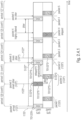
- Fig. 2.3.1 showing a timing diagram with configurations at the abscissa and time and the ordinate.
- the scheduling there is provided a first active configuration conf1 and a second active configuration conf2.
- the first and second active configurations conf1, conf2 are scheduled to transmit different RVs of the same data packet 122.
- a data packet 122' arrives at the buffer 102.
- a timing occasion occurs at instant TO122'0, in which a redundancy version RV0 of the data packet 122' is transmitted by the communication controller 114 and the antenna 110.
- a subsequent timing occasion occurs at instant TO122'3, in which a redundancy version RV3 of the data packet 122' is transmitted by the communication controller 114 and the antenna 110.
- a subsequent data packet 2 (122") undesirably happens to arrive at the buffer 102 at instant t122", which is after the transmission occasion TO122"0 (this is how to say that the data packet 2 arrives in the buffer 102 after a first delay or jitter threshold, which, when expires, permits to conclude that the data packet 2 has not arrived in time).
- the subsequent transmission occasion TO122"3 (which, according to the scheduling, should be assigned to a second redundancy version RV3 of the packet 122”) should not be used.
- the second jitter threshold may be associated, e.g., be equal or almost equal, to the shifting of the second configuration with respect to the first configuration. Therefore, if a second configuration is delayed of a certain time with respect to the first configuration, it is possible to switch to the second configuration when the packet 2 arrives within the second threshold, i.e. in time for being transmitted at the second configuration, e.g. within a delay which is less than the shift between the first and second configurations).
- the scheduling/reallocation unit 112 may reallocate, on the fly, the scheduled resources (e.g., a time slot, a frequency, etc.) and provide the modified scheduling 142 to the communication controller 114, so that the communication controller 114 transmits the data packets in accordance to the modified scheduling.
- the scheduled resources e.g., a time slot, a frequency, etc.
- the communication may be performed according to the predefined scheduling, without the necessity of reallocating resources. In that case, no resource reallocation is performed on the basis of the jitter information 147.
- the scheduling/reallocation unit may check whether the jitter 147 (as measured by the jitter determiner 106) is larger than a predetermined jitter threshold (as based on the transmission occasions as defined by the predefined scheduling): if the jitter 147 is larger than the predetermined jitter threshold, then a reallocation is performed; otherwise, no reallocation is performed.
- a predetermined jitter threshold as based on the transmission occasions as defined by the predefined scheduling
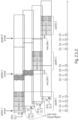
- Figure 2.3.2.a shows a timing diagram with time at the abscissa and resource configurations at the ordinate.
- a first active configuration conf1 is assigned, by the scheduling, with a slot S122 (instantiated by multiple slots S122', S122", S122′′′) for the transmission of a first redundancy version RV0 and a second redundancy version RV3 of a cyclical data packet 122 (instantiated by packets 122', 122", 122"', periodically arriving at the buffer 102).
- a first packet 122' (packet 1) arrives at the buffer 102.
- the instant t122' is before the timing occasion TO122'0 (start of the slot 122'), and the packet 1 may be transmitted by the communication controller 114 and the antenna 110 as packet 122t'.
- the transmitted first packet 122t' is transmitted using the first active configuration conf1.
- a first redundancy version RV0 of the received packet 122' is transmitted at a first part of the slot 122', starting from time instant TO122'0.
- the data packet 2 arrives (undesirably) at the buffer 102 at the unwanted time instant t122", which is after the first timing occasion TO122"0 defined by the scheduling (this is hot to say that the packet 122" arrives at the buffer 102 when the scheduled slot S122" has already started).
- an unwanted transmission hole may be generated, in the sense that the communication controller 114 and the antenna 110 do not transmit a valuable data.
- Figure 2.3.2.b shows a variant according to which, instead of transmitting the first redundancy version RV0 of the data packet 122t", the second active configuration conf2 transmits the second redundancy version RV3.
- the communication may be performed according to the predefined scheduling, without reallocating resources. In that case, no resource reallocation is performed on the basis of the jitter information 147.
- the scheduling/reallocation unit 112 may check whether the jitter 147 (as measured by the jitter determiner 106) is larger than a predetermined jitter threshold (as based on the transmission occasions as defined by the predefined scheduling): if the jitter 147 is larger than the predetermined jitter threshold, then a reallocation is performed; otherwise, no reallocation is performed.
- a first active configuration conf1 and a second active configuration conf2 are both used (e.g., at the same frequency), even conf1 and conf2 do not overlap (they use time slots which are not the same).
- the first active configuration conf1 provides the transmission of a first redundancy version RV0 at a first time slot
- the second active configuration conf2 provides the transmission of a second redundancy version RV3 at a second time slot (non-overlapping with the first time slot).
- a packet 122' correctly arrives at the buffer 102 at an instant t122', which is before the timing occasion TO122'0.
- the packet 122' is transmitted as packet 122t" by the communication controller 114 and the antenna 110 at the time slots defined by the first and second active configurations conf1, conf2, according to the scheduling.
- At least one redundancy version of the data packet may be transmitted in time. This is possible at least when the delayed arrival of the data packet 122" is at a delayed time instant t122", which is after the transmit occasion TO126"0 of the first active configuration conf1, but before the transmit occasion TO126"3 of the second active configuration conf2.
- an increased jitter impairs the arrival of the packet 122"', which is received in the buffer at the time instant t122"', which is after the timing occasion TO122"0 which, according to the scheduling and the first active configuration conf1, is foreseen as the start of the slot S122′′′ for the transmission of a first redundancy version RV0 of the packet 122"'.
- the scheduling/reallocation unit 112 may check whether the jitter 147 (as measured by the jitter determiner 106) is larger than a predetermined jitter threshold (as based on the transmission occasions as defined by the predefined scheduling): if the jitter 147 is larger than the predetermined jitter threshold, then a reallocation is performed; otherwise, no reallocation is performed.
- Figure 2.4.1 may be understood as showing multiple active configuration with variable RV-ID shift
- Fig. 2.4.1 shows an example in which the frequencies of the first and second active configurations conf1, conf2 are different (e.g., non-overlapping).
- the packet 4 (122"") (for which the first active configuration conf1 would prescribe the transmission at the slot S122""0) is transmitted at the slot S122 ⁇ ′′′0, while the subsequent slot S122 ⁇ ′′′3 may be used for transmitting the packet
- a data packet 122 periodically received by the buffer 102 may arrive, e.g. from different services (e.g., associated to different measurements or different applications or different uses) expected by the external device 119 from the UE 100.
- FIG. 2.4.3 An example is provided by Fig. 2.4.3 , in which different services 1 and 2 are served at different periods.
- a first active configuration conf1 is associated to a first band F0
- the second active configuration conf2 is associated to a second band F0+F1.
- the first and second band may be at least partially overlap.
- the second band F0+F1 may be broader than the first band F0.
- the first (narrower) band F0 may be used for transmitting data packets 122 for servicing the service 1.
- the second (broader) band F0+F1 may be used for transmitting data packets 126 for servicing the service 2. It is here hypothesized that the service 2 needs more band (e.g., more information to be transmitted in the one slot, even though the transmission rate may be lower).
- a first data packet 122' arrives (from service 1) at the instant t122' before the transmit occasion TO122'0, while no second data packet for service 2 arrives.
- the first data packet 122' is transmitted by the communication controller 114 and the antenna 110 as transmission 122' in the slots S122'0 and S122'3,
- a data packet 126' for service 1 arrives at the buffer 102.
- a packet 122"' (for service 1) is received by the buffer 102
- a packet 126" (for service 2) is received by the buffer 102.
- Both instants t122′′′ and t126" are after the timing occasion TO122′′′0 for transmitting at a first slot S122′′′0, but before the timing occasion TO 122"'3 for transmitting at a second (immediately subsequent) slot S122"3.
- a prioritization may be defined: some packets may be defined as having higher priority than other ones.
- the priority may be fixed (e.g., defined a priori) or variable, as in Fig. 2.4.3 : while the competition for the slot S122"3 has been wonby service 2, the competition for the slot 122′′′3 has been won by service 1.
- the priority may be therefore variable: for example, the priority may be changed alternatively for different services.
- other strategies may be adopted: for example, a first-in-first-out, FIFO, or last-in-first-out, LIFO strategy may be adopted.
- the prioritization may follow the quality of service, QoS, as experienced by the UE 100 and/or by the external device 119.
- the UE may choose, among different packets arriving from different services, the preferred data packet to be sent. For example, it is possible for the UE to decide the preferred data packet to be transmitted on the basis of a predetermined required maximum jitter, so as to give precedence to data packets whose required maximum jitter is closest to expire.
- this example relies on the jitter information 146 as provided by the jitter determiner 106 to the scheduling/reallocation unit 112.
- the scheduling/reallocation unit 112 may reallocate, on the fly, the scheduled resources (e.g., a time slot, a frequency, etc.) and provide the modified scheduling 142 to the communication controller 114, so that the communication controller 114 and the antenna 110 transmit the data packets in accordance to the modified scheduling.
- the UE 100 may be configured with two or more active configurations share part of the frequency domain so that at least one of the following assumptions may be valid:
- the UE 100 may be configured with two or more active configurations (e.g., conf1, conf2) may have different time offset: e.g., the time offset can be one or multiple slots/mini-slots/subframes/ OFDM symbols or multiple OFDM symbols.
- two or more active configurations e.g., conf1, conf2
- the time offset can be one or multiple slots/mini-slots/subframes/ OFDM symbols or multiple OFDM symbols.
- the UE 100 may be configured to use one active configuration (e.g., conf1) for a service (e.g., service 1) and another active configuration (e.g., conf2) for another service (e.g., service 2) for UL transmission
- one active configuration e.g., conf1
- another active configuration e.g., conf2
- another service e.g., service 2
- the UE 100 may be configured to prioritize any of the services based on the QoS or the jitter or the cumulative delay.
- the UE 100 may select (e.g., due to a jitter/delay and or QoS prioritization) to transmit one service that requires less resources (say F0 only), the UE 100 may still use the active configuration with more resources (F0 +F1):
- Figure 2.4.2 may be understood as showing multiple active configuration with variable RV-ID shift using same frequency and different time. Hint; every CG/SPS starts with RV0.
- Figure 2.5.2 similar to Figure 2.5.1 ; however, at least one of the following assertions may be valid:
- the UE can switch to the active configuration that is closer to the received data transmission.
- the set of reserved SPS active configurations can change.
- RVs redundancy versions
- Fig. 2.6 shows an example of a method 260 according to an example, which may be combined with features above.
- data packets 122, 126 are received, e.g., by the buffer 102 from an external device 119.
- a jitter 147 is measured (e.g., by the jitter determiner 106).
- a reallocation is performed (e.g., by modifying the scheduling on the fly), e.g., by the scheduling/reallocation unit 112.
- the transmissions are performed according to the reallocations (e.g., new scheduling), e.g., by the communication controller 114.
- the transmission configuration (i.e., the general transmission configuration between the UE and the BS) is a general concept including all the rules, protocols, etc. which permit the communication. There are included, for example, the frequencies, the scheduling, etc.
- first and/or second active configurations (conf1, conf2)
- the active configurations may be scheduled, and it is not necessary that each active configuration is always chosen.
- the UE may continue using the chosen active configuration up to the next late arrival of a subsequent data packet.
- the “transmission configuration” is therefore a general concept which may also encompass the concept of "(different) active configuration(s)” (e.g., SPS configurations), but is not necessarily the same.
- the UE may be to choose between the first and second active configurations so as to switch from one configuration to the chosen configuration without transmitting a request to a BS, hence increasing speed.
- the UE When operating at the first active configuration and in case of late arrival of a data packet, the UE may switch to the second active configuration for transmitting the late arrived data packet.
- the scheduling may provide for a configuration time offset (e.g., indicated with 242 in Fig. 2.4.2 ) of the second active configuration with respect to the first active configuration, so that, if a data packet 122" ( Fig. 2.4.2 ) arrives too late for being transmitted in the first active configuration but before the configuration time offset 242 elapses, the UE reallocates the late-arrived data packet 122", or at least a redundancy version thereof, to a resource of the second active configuration, and switches to the second active configuration (and in fact in Fig. 2.4.2 the transmitted packet 122t" is transmitted in one single RV, but is transmitted within only the time offset 242).
- a configuration time offset e.g., indicated with 242 in Fig. 2.4.2
- the UE may continue transmitting with the second active configuration up to a new necessity for switching to the first active configuration or to a different active configuration based on a subsequent late arrival of a data packet.
- the UE may, when choosing to switch to another active configuration, choose the active configuration (among a plurality of active configurations different from the first active configuration) which permits the transmission of the delayed data packet.
- the UE may receive BS's signalling defining the active configurations (e.g., by RRC).
- different active configurations have different resources for transmitting different RVs in different time slots. Another coverage may be to have either only time and/or time+frequency shift between the configurations. Different active configurations have different resources for transmitting different redundancy versions, RVs, in different frequencies.
- This solution is based, inter alia, on measuring or obtaining the jitter in the arrival of the data packets 122, 126, and, in case of necessity, in the request of modifying the timing of the scheduling.
- the UE 100 (which may be as in Fig. 1 ) may request to increase or reduce the length of the scheduling period.
- the UE 100 may request to modify the offset of the scheduling period (e.g. by shifting the scheduling period).
- this solution may be understood a distributed PLL, in which the BS synchronizes with the clock of the external device 119.
- the UE 100 is configured to transmit the delay or jitter information (146) and/or a scheduling and/or configuration modification request, so as to modify the transmission configuration and/or the scheduling.
- the UE may be configured to request to the BS some adjustments and/or some modifications.
- the UE may provide some information which will force the BS to modify the timing parameters of the scheduling, hence operating as a distributed PLL, in which the timing of the scheduling is synchronized by the BS to the clocks of the external device 119.
- the UE 100 may send the jitter information and/or the modification request and/or the configuration modification request to the BS. An updated of the scheduling may therefore be requested by the UE.
- the BS may receive the jitter information and/or the modification request and/or the configuration modification request. This information is collectively referred to as information 313.
- the BS may modify the scheduling according to the jitter information and/or the modification request and/or the configuration modification request (information 313). Hence, an update is carried out.
- the BS may signal the modified scheduling (or scheduling parameters, such as the timing parameters of the time period 120) to the UE.
- the information 313 sent by the UE 100 to the BS may include a determination on parameters associated to the jitter. These parameters (which may include, for example, parameters k1 and/or k2 as discussed below) may cause a reconfiguration of the scheduling (and in particular of the scheduling parameters of the communication).
- the UE 100 when periodically receiving at the buffer 102 the data packet 122, 126 from the external device, may determine that the period of provision of the data packets is different from the UE's expected period (this may be due to the non-synchronization of the timing module of the external device 119 with respect to the timing module 108 of the UE 100). Therefore, the UE (e.g., at the jitter determiner 106) may determine a scaling parameter k1 which would permit to resynchronize the scheduling period to the provision period of the arriving the data packet 122, 126 at the buffer 102.
- the parameters k1 and k2 are calculated by the BS on the basis of the feedback information 313 (e.g., delay or jitter information) provided by the UE 100. In that case, k1 and/or k2 may be modified at step 316.
- the feedback information 313 e.g., delay or jitter information
- the delay or jitter information may include a jitter trend information.
- the jitter trend information may include information on the evolution of the jitter during subsequent scheduling periods.
- the jitter trend information may provide information on the increasing or decreasing jitter, for example.
- ⁇ T 1 is a first difference between the arrival of a first data packet (e.g., 122") in the buffer (e.g., 102) and the subsequent timing occasion (e.g., TO122"0);
- ⁇ T 2 is a second difference between the arrival of a second, subsequent data packet (e.g., 122′′′) in the buffer (e.g., 102) and the subsequent timing occasion (e.g., TO122′′′0) for transmitting the second data packet (e.g., 122"');
- “period” is the length of the current determined period (e.g., 122), to provide a value of the jitter trend.
- the jitter trend may be updated at each period.
- the jitter trend may be signalled to the Bs with the information 313.
- An example of trend information may be (with reference to Fig. 2.3.2 ):
- the jitter trend information it may be possible (e.g., by the BS and/or by the jitter determiner 106 and/or the scheduling/reallocation unit 112) to foresee the future jitter, and, in case, to adopt a strategy to compensate it.
- the SPS_period may be the scheduling time period. It is here important to understand that the transmission configuration may be modified by the BS, on UE's demand, on the basis of the delay or jitter information 146 obtained by the jitter determiner 106.
- the features of the embodiment E2 may be combined with those of the embodiment E1.
- the UE may:
- k1 and k2 may be used for scaling time durations which may be one of sTTIs, slots, mini-slots, durations of OFDM symbols, etc.
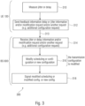
- This embodiment may also be illustrated as a variant of E2 and can be also shown in Fig. 3 .
- the UE 100 may be as in Fig. 1 .
- the UE 100 may send a feedback (step 312) to the BS (e.g., gNB) with some information 313 (e.g., codified in a control data field) regarding the delay or jitter (delay or jitter information 146) for adapting the CG/SPS accordingly.
- This may be via uplink (UL) control information (UCI) feedback and/or in Data control feedback and/or UE assisting information (all this information may be resumed with the concept of delay or jitter information).
- This UE assisting information may include information about the traffic arrival, delays, and data periodicity; this may be sent periodically or on-demand, according to the examples.
- the BS may sense or predict the jitter or decode the jitter from a UE assisting information.
- the BS e.g., gNB
- the BS may update the existing configuration period (with k1) or update the CG/SPS offset (with k2).
- the BS may send an SPS/Configured-Grant update message, e.g., RRC ConfiguredGrantConfigUpdate, with any of the following:
- the UE 100 may be configured to receive, from the base station, BS, signalling regarding the transmission configuration.
- the signalling may be at least partially based on the at least one of the delay or jitter information (e.g., 146), scheduling modification request, configuration modification request, and feedback information, so as to modify the transmission configuration and/or the scheduling.
- the UE may be configured to receive, from the BS, signalling regarding the transmission configuration, the signalling being at least partially based on measurements performed by the BS or by another device associate to the BS.
- the UE may:
- At least one of the following may apply:
- the UE 100 may send to the BS additional information (which may also be understood as delay or jitter information).
- the UE may be as in Fig. 1 .
- the embodiment is also shown in Fig. 3 .
- the UE 100 may request additional new SPS/CG configuration(s) by sending a jitter-correction report or extend one existing measurement REPORTS (e.g., CSI reports, SPS reports, or new reports).
- This report or feedback information can be conveyed via UCI message or in UL Data control information. At least one of the following assertions may be valid:
- the SPS_period may be the scheduling time period. It is here important to understand that the transmission configuration may be modified by the BS, on the basis of the UE's feedback report demand, on the basis of the delay or jitter information 146 obtained by the jitter determiner 106.
- the UE may:
- the request 313 may be a request including at least one of:
- the additional configuration request (313) may include a request of changed time index or time offset of the determined time period.
- the BS may provide a changed time index or time offset of the determined time period.
- the UE may therefore change the time index or time offset of the determined time period.
- the UE may expect an additional configuration update message in the RRC including the updated time period. When received, the UE may update the time period.
- the UE may expect an additional configuration update message in the L1 signalling, e.g., DCI, including the updated time period.
- the UE may update the time period.
- the UE may expect an additional configuration update message in the RRC including the updated time index or time offset. When received, the UE may update the time index or time offset.
- the UE may expect an additional configuration update message in the L1 signalling, e.g., DCI, including the updated time index or time offset.
- the UE may update the time index or time offset.
- the LUT 113 may provide a quantized version of at least some of the delay information or jitter information, so as to provide the quantized version or jitter information.
- the IE ConfiguredGrantConfig may be used to configure uplink transmission without dynamic grant according to two possible schemes.
- the actual uplink grant may either be configured via RRC (type1) or provided via the PDCCH (addressed to CS-RNTI) (type2).
- frequencyHoppingOffset Enables intra-slot frequency hopping with the given frequency hopping offset.
- Frequency hopping offset used when frequency hopping is enabled.
- L1 parameter 'Frequency-hopping-offset' (see TS 38.214, section 6.1.2).
- mcs-Table Indicates the MCS table the UE shall use for PUSCH without transform precoding. If the field is absent the UE applies the value 64QAM.
- mcs-TableTransformPrecoder Indicates the MCS table the UE shall use for PUSCH with transform precoding. If the field is absent the UE applies the value 64QAM.
- mcsAndTBS The modulation order, target code rate and TB size (see TS38.214, section 6.1.2).
- nrofHARQ-Processes The number of HARQ processes configured. It applies for both Type 1 and Type 2. See TS 38.321, section 5.4.1. p0-PUSCH-Alpha Index of the P0-PUSCH-AlphaSet to be used for this configuration. periodicity Periodicity for UL transmission without UL grant for type 1 and type 2. Corresponds to L1 parameter 'UL-TWG-periodicity' (see TS 38.321, section 5.8.2).
- rrc-ConfiguredUplinkGrant Configuration for "configured grant" transmission with fully RRC-configured UL grant (Type1).If this field is absent the UE uses UL grant configured by DCI addressed to CS-RNTI (Type2).
- Type 1 confgured grant may be configured for UL or SUL, but not for both simultaneously.
- timeDomainAllocation Indicates a combination of start symbol and length and PUSCH mapping type, see TS 38.214, section 6.1.2 and TS 38.212, section 7.3.1.
- timeDomainOffset Offset related to SFN 0, see TS 38.321, section 5.8.2. transformPrecoder Enable transformer precoder for type1 and type2.
- the base station, BS 600 may comprise at least one of:
- the scheduler 630 may be configured to define and/or adapt the scheduling on the basis of at least feedback information, from the UE, regarding the delay or jitter information and/or a scheduling modification request, from the UE, based on delay or jitter information [e.g., according to the UE measurements]. All this information may be indicated with 313.
- the scheduler 630 may be configured to update the length of the time period, e.g., on the basis of a feedback from the UE and/or on the basis of a request from the UE and/or on the basis of delay or jitter information from the UE.
- the scheduler 630 may be configured to update the index of the time period and/or to shift the time period, e.g., on the basis of a feedback from the UE and/or on the basis of a request from the UE and/or on the basis of delay or jitter information from the UE.
- scheduler 630 and/or BS 600 may be understood from the explanations above regarding the UE 100 (as the UL and/or DL and/or signalling transmissions may be performed with the BS 600 and/or on the basis of the scheduling defined by the scheduler 630.
- the BS 600 may be configured to transmit signalling regarding the transmission configuration.
- the signalling may be at least partially based on the at least one of the delay or delay or jitter information (e.g., 146), scheduling modification request, configuration modification request, and feedback information as transmitted from the UE to the BS. Accordingly, the BS may modify the transmission configuration and/or the scheduling.
- the BS may transmit signalling regarding the transmission configuration, the signalling being at least partially based on measurements performed by the BS or by another device associate to the BS (e.g., another device at the network side).
- the BS 600 may update the scheduling (e.g., by signalling values k1 and/or k2) to the UE.
- Fig. 2.2.2 shows a unit 700 including the UE 100 (some elements not being shown) and the local external device 119.
- the external device 119 may include a sensor 702 acquiring physical measurements on the environment (e.g., any of electrical, mechanical, chemical magnitude(s), etc.).
- the external device 119 may include a processor 705.
- the external device 119 may include a timing (clock) module 708, which is in principle different from the timing (clock) module 108 of the UE 100.
- the external device 119 may (e.g., periodically) send (e.g., through electrical connections, e.g., without wireless connections) data packets 122, 126 to the buffer 102 of the UE 100.
- the unit 700 may receive the data packets 122, 126 from the external device 119 and retransmit them (as data packets 121t, 126t) to a remote unit 800 through the BS 600 (in Fig. 2.2.2 only one BS 600 is shown, but it is clear that a plurality of BSs may be involved, as a common network may be used). Techniques for transmitting the data packets 122t, 126t are discussed above.
- the remote unit 800 may retransmit data packets (e.g., as packets 122tt, 126tt) to the unit 700 through the BS 600 and/or more in general through the network.
- data packets e.g., as packets 122tt, 126tt
- the remote system 900 may be, for example, an internet-of-things, loT, system.
- the data carrier medium, the digital storage medium or the recorded medium are tangible and/or non-transitionary, rather than signals which are intangible and transitory.
- a further example of the method is, therefore, a data stream or a sequence of signals representing the computer program for performing one of the methods described herein.
- the data stream or the sequence of signals may for example be transferred via a data communication connection, for example via the Internet.
- a further example comprises a processing means, for example a computer, or a programmable logic device performing one of the methods described herein.
- a further example comprises a computer having installed thereon the computer program for performing one of the methods described herein.
- a further example comprises an apparatus or a system transferring (for example, electronically or optically) a computer program for performing one of the methods described herein to a receiver.
- the receiver may, for example, be a computer, a mobile device, a memory device or the like.
- the apparatus or system may, for example, comprise a file server for transferring the computer program to the receiver.
- a programmable logic device for example, a field programmable gate array
- a field programmable gate array may cooperate with a microprocessor in order to perform one of the methods described herein.
- the methods may be performed by any appropriate hardware apparatus.
- some aspects relate to a user equipment, UE, including
- BS e.g., gNB, e.g., for receiving data [e.g., in UL] from a UE
- a network coordinator e.g., for vehicle to vehicle communications and/or user to user communications, comprising:
- the BS as above, wherein the scheduler may be configured to update the length of the time period, e.g., on the basis of a feedback from the UE and/or on the basis of a request from the UE and/or on the basis of jitter information from the UE.
- the BS as above, wherein the scheduler may be configured to update the index of the time period and/or to shift the time period, e.g., on the basis of a feedback from the UE and/or on the basis of a request from the UE and/or on the basis of jitter information from the UE.
- some aspects relate to a system comprising a BS and at least one UE, wherein:
- some aspects relate to a UE [e.g., as any of the above] for the transmission [e.g., in UL to a BS and/or to a network coordinator], configured to:
- some aspects relate to a UE [e.g., as any of the above] for the transmission [e.g., in UL to a BS and/or a network coordinator], configured to:
- some aspects relate to a UE [e.g., as any of the above] for the transmission in[e.g., in UL to a BS and/or a network coordinator], configured to: measure [e.g., by the jitter determiner] a jitter trend information [e.g., the modification of the jitter between the current period and the previous period or an average, e.g., a weighted average, of the previous jitters][e.g., the jitter being between the arrival in the buffer and the transmission in UL and/or to a network coordinator], and/or provide, as a feedback information [e.g., based on the jitter trend information] , information associated to at least one of the following scenarios: scenario Use case 1/Problem 1 Missmatch between packet arrival and the machine clocks Use case 2/Problem 2 Delay due to packet congestion (congestion control mechanism) Use case 3/Problem 3 Factory automation with multiple machines clocks Use case 4/Problem 4 Synchro
- the UE may be further configured to: request a particular scheduling period [e.g., SPS period] [e.g., to the BS and/or the network coordinator].
- a particular scheduling period e.g., SPS period
- the UE may be further configured to: request a particular updating [e.g., by providing new_SPS_Period] of the length of the period [e.g., to the BS and/or the network coordinator].
- a particular updating e.g., by providing new_SPS_Period] of the length of the period [e.g., to the BS and/or the network coordinator].
- the UE may be further configured to provide a value of the jitter trend [e.g., to the BS and/or the network coordinator] [the jitter trend may be the increment on the jitter from the previous period to the current period and/or the increment on the jitter from an average regarding previous periods and the current period].
- the jitter trend may be the increment on the jitter from the previous period to the current period and/or the increment on the jitter from an average regarding previous periods and the current period.
- the UE may be further configured so as to, in case of determination of failure of the scheduling/modification, to perform a redundancy strategy.
- the UE may be further configured, wherein a failure of the scheduling/modification is determined when no quantized version of the jitter information or jitter trend information is found (e.g., is not in the LUT)
- the UE may be further configured, wherein a failure of the scheduling/modification is determined when the BS fails to modify the scheduling/modification [e.g., within a predetermined threshold].
- the UE may be further configured, wherein a failure of the scheduling/modification is determined when the UE fails to obtain the jitter information or jitter trend information [e.g., within a predetermined threshold].
- the UE may be further configured to estimate a hyper-period [e.g., as the least common multiple, LCM between the period as for the timing (clock) module of the UE and the period as for the timing (clock) module of the external device inserting the data packets onto the buffer]
- the UE may be further configured to define the maximum allowed jitter between the length (e.g., sTTI) of the time slot for the first RV [and/or for a resource] and the length of the time period.
- the UE may be further configured so that the number of configurations [and/or different allocations of resources] is associated to the length of the period and the maximum allowed jitter (e.g. the fraction between these values and/or the ceiling of the fraction, wherein the fraction may be, for example, the value of the hyper-period; other methods for calculating the hyper period may be carried out)
- the UE may be further configured so that the number of configurations is associated to the hyper period.
- the UE may be further configured so thatdifferent configurations have different resources for transmitting different RVs in different time slots.
- some aspects relate to a BS, [e.g., as above] or a network coordinator comprising a scheduler configured to define and/or modify the scheduling period [e.g., SPS period] on the basis of at least one of:
- the UE may be further configured to perform, as redundancy strategy: in case the subsequent data packet arrives in the buffer before the first maximum jitter threshold, transmit the first RV of the subsequent data packet in the first resource of the subsequent period instead of the first RV of the first data packet.
- the UE may be further configured to perform, as redundancy strategy: reallocate the transmission of the second RV in the first resource in the subsequent period.
- the UE may be further configured to perform, as a redundancy strategy: in case the subsequent data packet arrives in the buffer before the first maximum jitter threshold [e.g., in time for transmitting the first RV], avoid the transmission of the first RV of the first data packet and actually transmit the first RV of the subsequent data packet in the first resource.
- the first maximum jitter threshold e.g., in time for transmitting the first RV
- some aspects relate to a UE [e.g., as any of the UEs above] configured to perform, as redundancy strategy, transmit a plurality of RVs of the same data packet periodically arrived in a buffer, wherein at least one RV is a self-decodable RV and at least one RV is a non-self-decodable RV, configured to: in case of late reception of a data packet after a first maximum jitter threshold for transmitting a first decodable RV but before a second maximum jitter threshold for transmitting a second non-decodable RV, to reallocate the transmission of the RVs so that: at least one self-decodable RV is transmitted before at least one non-self-decodable RV.
- a method may include
- a method may include
- a storage unit may be configured to store instructions which, when executed by a processor, cause the processor to perform a method and/or to implement any of the functions above.
- Base station may be the BS below
- SCI Sidelink Control Information SL sidelink sTTI Short Transmission Time Interval TDM Time Division Multiplexing TDMA Time Division Multiple Access UE User Entity (User Terminal) URLLC Ultra-Reliable Low-Latency Communication
- V2V Vehicle-to-vehicle V2I Vehicle-to-infrastructure
- V2P Vehicle-to-pedestrian V2N Vehicle-to-to-
Landscapes
- Engineering & Computer Science (AREA)
- Computer Networks & Wireless Communication (AREA)
- Signal Processing (AREA)
- Quality & Reliability (AREA)
- Mobile Radio Communication Systems (AREA)
Claims (13)
- Ein Nutzergerät, UE, (100) zum Senden von drahtlosen Übertragungen, wobei das UE angepasst ist zum:Empfangen von Datenpaketen (122, 126) von einer externen Vorrichtung (119), die eine lokale Vorrichtung ist;Senden der Datenpakete (142) gemäß einer Zeitplanung, die Übertragungsressourcen in einer bestimmten Zeitperiode (P) zuweist;Bestimmen einer Verzögerungsinformation (146) zwischen dem Empfang eines Datenpakets (122, 126) in dem Puffer (102) und der Übertragung des Datenpakets (122, 126); undModifizieren der Übertragungskonfiguration, um von einer ersten aktiven Konfiguration zu einer zweiten aktiven Konfiguration zu schalten,wobei die aktiven Konfigurationen derart sind, dass für jeden Zeitschlitz nur eine aktive Konfiguration ein Datenpaket sendet, das eine anfängliche Übertragung und alle möglichen Redundanzversionen, RV, des Datenpakets umfasst, wobei das UE eine Definition der ersten aktiven Konfiguration (conf1) und der zweiten aktiven Konfiguration (conf2) in einer BS-Signalisierung empfangen soll,wobei das UE dazu konfiguriert ist, wenn dasselbe mit der ersten aktiven Konfiguration arbeitet und im Fall einer späten Ankunft eines Datenpakets, zum Senden des spät angekommenen Datenpakets zu der zweiten aktiven Konfiguration zu schalten.
- Das UE gemäß Anspruch 1, wobei unterschiedliche aktive Konfigurationen unterschiedliche Ressourcen zum Senden unterschiedlicher Redundanzversionen, RV, in unterschiedlichen Zeitschlitzen aufweisen.
- Das UE gemäß einem der Ansprüche 1 bis 2, wobei das UE zwischen der ersten und der zweiten aktiven Konfiguration wählen soll, um von einer Konfiguration zu der gewählten Konfiguration zu schalten, ohne eine Anforderung an ein BS zu senden.
- Das UE gemäß einem der vorhergehenden Ansprüche, wobei das UE, wenn dasselbe zu der zweiten aktiven Konfiguration schaltet, eine Redundanzversion, RV, eines Datenpakets einer Ressource der zweiten aktiven Konfiguration neu zuweisen soll.
- Das UE gemäß einem der vorhergehenden Ansprüche, wobei die Zeitplanung einen Konfigurationszeitversatz (242) der zweiten aktiven Konfiguration in Bezug auf die erste aktive Konfiguration bereitstellt, so dass, falls ein Datenpaket zu spät, um in der ersten aktiven Konfiguration gesendet zu werden, aber vor dem Konfigurationszeitversatz ankommt, das UE das Datenpaket oder zumindest eine Redundanzversion desselben einer Ressource der zweiten aktiven Konfiguration neu zuweist und zu der zweiten aktiven Konfiguration schaltet.
- Das UE gemäß Anspruch 5, wobei das UE nach dem Schalten zu der zweiten aktiven Konfiguration das Senden mit der zweiten aktiven Konfiguration fortsetzen soll, bis zu einer neuen Notwendigkeit zum Schalten zu der ersten aktiven Konfiguration oder zu einer anderen aktiven Konfiguration basierend auf einer nachfolgenden späten Ankunft eines Datenpakets.
- Das UE gemäß einem der vorhergehenden Ansprüche, wobei die erste und die zweite aktive Konfiguration eine gleiche Zeitressource mit der gleichen Frequenz gemeinschaftlich verwenden, die zweite aktive Konfiguration eine aktive Schattenkonfiguration ist und das UE nur gemäß der ersten aktiven Konfiguration sendet, wobei das UE zu der zweiten aktiven Konfiguration schalten soll, falls ein Datenpaket zu spät ankommt, um gemäß der ersten aktiven Konfiguration gesendet zu werden.
- Das UE gemäß einem der vorhergehenden Ansprüche, wobei zumindest eine RV selbstdecodierbar ist und zumindest eine RV nicht selbstdecodierbar ist, wobei nach der späten Ankunft eines Datenpakets eine Konkurrenz zwischen einer selbstdecodierbaren RV und einer nicht selbstdecodierbaren RV durch Senden der selbstdecodierbaren RV gelöst wird.
- Das UE gemäß einem der vorhergehenden Ansprüche, das dazu angepasst ist, Folgendes durchzuführen:
falls ein Datenpaket (122") nicht rechtzeitig für eine Übertragung (122t") an einem aktuellen Schlitz (S122"0) aber rechtzeitig für eine Übertragung in einem nachfolgenden Schlitz (S122"3) ankommt, Senden des Datenpakets (122") in dem nachfolgenden Schlitz (S122"3), wobei das UE, wenn das Datenpaket (122") in dem nachfolgenden Schlitz (S122"3) gesendet wird, die Übertragung eines anderen Datenpakets, das für den nachfolgenden Schlitz (S122"3) geplant ist, verschieben soll. - Das UE gemäß einem der vorhergehenden Ansprüche, wobei das UEein Verhältnis Ratio_1 = (ΔT 1 - ΔT 2 )/ period bereitstellen soll,wobei ΔT 1 eine erste Differenz zwischen der Ankunft eines ersten Datenpakets (122") und dem nachfolgenden Zeitgebungsanlass (TO122"0) ist, wobei ΔT 2 eine zweite Differenz zwischen der Ankunft eines zweiten, nachfolgenden Datenpakets (122‴) und dem nachfolgenden Zeitgebungsanlass (TO122"'0) zum Senden des zweiten Datenpakets (122"') ist, wobei "period" die Länge der aktuellen bestimmten Periode (122) ist, um einen Wert der Verzögerungstendenz bereitzustellen.
- Das UE gemäß einem der Ansprüche 1-10, wobei das UE die Datenpakete gemäß einer semipersistenten Zeitplanung, SPS, senden soll.
- Ein Verfahren für ein Nutzergerät, UE, wobei das Verfahren folgende Schritte aufweist:periodisches Empfangen von Datenpaketen von einer lokalen, externen Vorrichtung;Senden der Datenpakete gemäß einer Zeitplanung, die Übertragungsressourcen in einer Zeitperiode zuweist, wobei die Zeitperiode konfigurierbar ist; und Bestimmen einer Verzögerungsinformation zwischen dem Empfang eines Datenpakets und der Übertragung des Datenpakets,Modifizieren der Übertragungskonfiguration, um von einer ersten aktiven Konfiguration zu einer zweiten aktiven Konfiguration zu schalten, um, wenn dasselbe mit der ersten aktiven Konfiguration arbeitet und im Fall einer späten Ankunft eines Datenpakets, zum Senden des spät angekommenen Datenpakets zu der zweiten aktiven Konfiguration zu schalten,wobei die aktiven Konfigurationen derart sind, dass für jeden Zeitschlitz nur eine aktive Konfiguration ein Datenpaket sendet, das eine anfängliche Übertragung und alle möglichen Redundanzversionen, RV, des Datenpakets umfasst, so dass das UE eine Definition der ersten aktiven Konfiguration (conf1) und der zweiten aktiven Konfiguration (conf2) in einer BS-Signalisierung empfängt.
- Eine Speichereinheit, die Anweisungen speichert, die, wenn dieselben durch einen Prozessor ausgeführt werden, den Prozessor veranlassen, das Verfahren gemäß Anspruch 12 durchzuführen.
Applications Claiming Priority (2)
| Application Number | Priority Date | Filing Date | Title |
|---|---|---|---|
| EP18197382 | 2018-09-27 | ||
| PCT/EP2019/072054 WO2020064215A1 (en) | 2018-09-27 | 2019-08-16 | Enhancements for urllc sps to cope with timing drifts between a wireless network and a ue-side application |
Publications (2)
| Publication Number | Publication Date |
|---|---|
| EP3857944A1 EP3857944A1 (de) | 2021-08-04 |
| EP3857944B1 true EP3857944B1 (de) | 2025-04-09 |
Family
ID=63832174
Family Applications (1)
| Application Number | Title | Priority Date | Filing Date |
|---|---|---|---|
| EP19752725.2A Active EP3857944B1 (de) | 2018-09-27 | 2019-08-16 | Verbesserungen für urllc-sps zum meistern von zeitdrifts zwischen einem drahtlosen netzwerk und einer benutzergeräteseitigen anwendung |
Country Status (3)
| Country | Link |
|---|---|
| EP (1) | EP3857944B1 (de) |
| ES (1) | ES3034783T3 (de) |
| WO (1) | WO2020064215A1 (de) |
Cited By (1)
| Publication number | Priority date | Publication date | Assignee | Title |
|---|---|---|---|---|
| US20240357587A1 (en) * | 2021-08-30 | 2024-10-24 | Lenovo (Beijing) Limited | Methods and apparatuses for uplink transmission |
Families Citing this family (6)
| Publication number | Priority date | Publication date | Assignee | Title |
|---|---|---|---|---|
| CN114375047B (zh) * | 2020-10-15 | 2026-03-31 | 大唐移动通信设备有限公司 | 资源调度方法、系统、设备及存储介质 |
| US12349121B2 (en) | 2020-10-23 | 2025-07-01 | Apple Inc. | Methods and apparatus for support of data transmission traffic with non-integer periodicity in wireless communication |
| EP4427529A1 (de) * | 2021-11-05 | 2024-09-11 | Telefonaktiebolaget LM Ericsson (publ) | Jitterebenenabhängige planung von drahtlosen übertragungen |
| CN116249101A (zh) * | 2021-12-07 | 2023-06-09 | 华为技术有限公司 | 数据传输方法和数据传输装置 |
| KR20260006657A (ko) * | 2023-05-12 | 2026-01-13 | 베이징 시아오미 모바일 소프트웨어 컴퍼니 리미티드 | 정보 처리 방법, 장치, 통신 디바이스 및 저장 매체 |
| CN121400003A (zh) * | 2023-08-24 | 2026-01-23 | 株式会社Ntt都科摩 | 终端、无线基站以及无线通信方法 |
Family Cites Families (5)
| Publication number | Priority date | Publication date | Assignee | Title |
|---|---|---|---|---|
| US4751725A (en) * | 1987-01-30 | 1988-06-14 | Motorola, Inc. | VOX remote unit control in a cellular system |
| US7039418B2 (en) * | 2000-11-16 | 2006-05-02 | Qualcomm Incorporated | Position determination in a wireless communication system with detection and compensation for repeaters |
| US9003220B2 (en) * | 2012-09-07 | 2015-04-07 | National Instruments Corporation | Switch for clock synchronization over a switched fabric |
| WO2014040642A1 (en) * | 2012-09-14 | 2014-03-20 | Huawei Technologies Co., Ltd. | Method for energy saving in a cellular communication system |
| WO2016019555A1 (en) * | 2014-08-07 | 2016-02-11 | Nec Corporation | Method and apparatus for channel state information measurement |
-
2019
- 2019-08-16 EP EP19752725.2A patent/EP3857944B1/de active Active
- 2019-08-16 ES ES19752725T patent/ES3034783T3/es active Active
- 2019-08-16 WO PCT/EP2019/072054 patent/WO2020064215A1/en not_active Ceased
Cited By (1)
| Publication number | Priority date | Publication date | Assignee | Title |
|---|---|---|---|---|
| US20240357587A1 (en) * | 2021-08-30 | 2024-10-24 | Lenovo (Beijing) Limited | Methods and apparatuses for uplink transmission |
Also Published As
| Publication number | Publication date |
|---|---|
| ES3034783T3 (en) | 2025-08-22 |
| WO2020064215A1 (en) | 2020-04-02 |
| EP3857944A1 (de) | 2021-08-04 |
Similar Documents
| Publication | Publication Date | Title |
|---|---|---|
| EP3857944B1 (de) | Verbesserungen für urllc-sps zum meistern von zeitdrifts zwischen einem drahtlosen netzwerk und einer benutzergeräteseitigen anwendung | |
| RU2735635C2 (ru) | Улучшения планирования для систем беспроводной связи ограниченной латентности и высокой надежности | |
| JP7533667B2 (ja) | 通信システム | |
| US12362865B2 (en) | HARQ process / entity based uplink multiplexing | |
| US8831034B2 (en) | Methods and apparatus for handling time alignment in a cell with extended cell range | |
| AU2010284941B2 (en) | Controlling a transmission of information in a wireless communication network with a relay node | |
| US8493925B2 (en) | Method for communicating in a network, a secondary station and a system therefor | |
| KR101999852B1 (ko) | 네트워크에서 통신하기 위한 방법, 제 2 스테이션 및 이를 위한 시스템 | |
| US11937334B2 (en) | Method and apparatus for sidelink discontinuous reception in a wireless communication system | |
| US9560670B2 (en) | Method of managing coexisting packet streams | |
| Won et al. | 3GPP URLLC patent analysis | |
| WO2020088776A1 (en) | Enhanced bearer establishment for supporting deterministic traffic | |
| US20090109960A1 (en) | Method and apparatus for a virtual circuit data area within a packet data frame | |
| CN119014102A (zh) | 无线网络中的周期性通信的动态调度 | |
| WO2026032596A1 (en) | Dsr trigger for scheduling restrictions/measurement gaps | |
| WO2026032595A1 (en) | Dsr trigger for scheduling restrictions/measurement gaps | |
| HK1164562A1 (en) | Method and system for dynamic adjustment of downlink/uplink allocation ratio in lte/tdd systems | |
| HK1164562B (en) | Method and system for dynamic adjustment of downlink/uplink allocation ratio in lte/tdd systems |
Legal Events
| Date | Code | Title | Description |
|---|---|---|---|
| STAA | Information on the status of an ep patent application or granted ep patent |
Free format text: STATUS: UNKNOWN |
|
| STAA | Information on the status of an ep patent application or granted ep patent |
Free format text: STATUS: THE INTERNATIONAL PUBLICATION HAS BEEN MADE |
|
| PUAI | Public reference made under article 153(3) epc to a published international application that has entered the european phase |
Free format text: ORIGINAL CODE: 0009012 |
|
| STAA | Information on the status of an ep patent application or granted ep patent |
Free format text: STATUS: REQUEST FOR EXAMINATION WAS MADE |
|
| 17P | Request for examination filed |
Effective date: 20210318 |
|
| AK | Designated contracting states |
Kind code of ref document: A1 Designated state(s): AL AT BE BG CH CY CZ DE DK EE ES FI FR GB GR HR HU IE IS IT LI LT LU LV MC MK MT NL NO PL PT RO RS SE SI SK SM TR |
|
| DAV | Request for validation of the european patent (deleted) | ||
| DAX | Request for extension of the european patent (deleted) | ||
| RAP3 | Party data changed (applicant data changed or rights of an application transferred) |
Owner name: FRAUNHOFER-GESELLSCHAFT ZUR FOERDERUNG DER ANGEWANDTEN FORSCHUNG E.V. |
|
| STAA | Information on the status of an ep patent application or granted ep patent |
Free format text: STATUS: EXAMINATION IS IN PROGRESS |
|
| 17Q | First examination report despatched |
Effective date: 20230203 |
|
| GRAP | Despatch of communication of intention to grant a patent |
Free format text: ORIGINAL CODE: EPIDOSNIGR1 |
|
| STAA | Information on the status of an ep patent application or granted ep patent |
Free format text: STATUS: GRANT OF PATENT IS INTENDED |
|
| RIC1 | Information provided on ipc code assigned before grant |
Ipc: H04W 88/04 20090101ALN20240516BHEP Ipc: H04W 72/54 20230101ALI20240516BHEP Ipc: H04W 56/00 20090101ALI20240516BHEP Ipc: H04W 24/08 20090101AFI20240516BHEP |
|
| INTG | Intention to grant announced |
Effective date: 20240531 |
|
| P01 | Opt-out of the competence of the unified patent court (upc) registered |
Free format text: CASE NUMBER: APP_44938/2024 Effective date: 20240802 |
|
| GRAJ | Information related to disapproval of communication of intention to grant by the applicant or resumption of examination proceedings by the epo deleted |
Free format text: ORIGINAL CODE: EPIDOSDIGR1 |
|
| STAA | Information on the status of an ep patent application or granted ep patent |
Free format text: STATUS: EXAMINATION IS IN PROGRESS |
|
| GRAP | Despatch of communication of intention to grant a patent |
Free format text: ORIGINAL CODE: EPIDOSNIGR1 |
|
| STAA | Information on the status of an ep patent application or granted ep patent |
Free format text: STATUS: GRANT OF PATENT IS INTENDED |
|
| INTC | Intention to grant announced (deleted) | ||
| RIC1 | Information provided on ipc code assigned before grant |
Ipc: H04W 88/04 20090101ALN20240926BHEP Ipc: H04W 72/54 20230101ALI20240926BHEP Ipc: H04W 56/00 20090101ALI20240926BHEP Ipc: H04W 24/08 20090101AFI20240926BHEP |
|
| RIC1 | Information provided on ipc code assigned before grant |
Ipc: H04W 88/04 20090101ALN20241003BHEP Ipc: H04W 72/54 20230101ALI20241003BHEP Ipc: H04W 56/00 20090101ALI20241003BHEP Ipc: H04W 24/08 20090101AFI20241003BHEP |
|
| INTG | Intention to grant announced |
Effective date: 20241009 |
|
| GRAS | Grant fee paid |
Free format text: ORIGINAL CODE: EPIDOSNIGR3 |
|
| GRAA | (expected) grant |
Free format text: ORIGINAL CODE: 0009210 |
|
| STAA | Information on the status of an ep patent application or granted ep patent |
Free format text: STATUS: THE PATENT HAS BEEN GRANTED |
|
| AK | Designated contracting states |
Kind code of ref document: B1 Designated state(s): AL AT BE BG CH CY CZ DE DK EE ES FI FR GB GR HR HU IE IS IT LI LT LU LV MC MK MT NL NO PL PT RO RS SE SI SK SM TR |
|
| REG | Reference to a national code |
Ref country code: GB Ref legal event code: FG4D |
|
| REG | Reference to a national code |
Ref country code: CH Ref legal event code: EP |
|
| REG | Reference to a national code |
Ref country code: DE Ref legal event code: R096 Ref document number: 602019068419 Country of ref document: DE |
|
| REG | Reference to a national code |
Ref country code: IE Ref legal event code: FG4D |
|
| REG | Reference to a national code |
Ref country code: NL Ref legal event code: FP |
|
| REG | Reference to a national code |
Ref country code: ES Ref legal event code: FG2A Ref document number: 3034783 Country of ref document: ES Kind code of ref document: T3 Effective date: 20250822 |
|
| PGFP | Annual fee paid to national office [announced via postgrant information from national office to epo] |
Ref country code: NL Payment date: 20250826 Year of fee payment: 7 |
|
| REG | Reference to a national code |
Ref country code: AT Ref legal event code: MK05 Ref document number: 1784709 Country of ref document: AT Kind code of ref document: T Effective date: 20250409 |
|
| PG25 | Lapsed in a contracting state [announced via postgrant information from national office to epo] |
Ref country code: PT Free format text: LAPSE BECAUSE OF FAILURE TO SUBMIT A TRANSLATION OF THE DESCRIPTION OR TO PAY THE FEE WITHIN THE PRESCRIBED TIME-LIMIT Effective date: 20250811 Ref country code: FI Free format text: LAPSE BECAUSE OF FAILURE TO SUBMIT A TRANSLATION OF THE DESCRIPTION OR TO PAY THE FEE WITHIN THE PRESCRIBED TIME-LIMIT Effective date: 20250409 |
|
| PGFP | Annual fee paid to national office [announced via postgrant information from national office to epo] |
Ref country code: ES Payment date: 20250902 Year of fee payment: 7 |
|
| PGFP | Annual fee paid to national office [announced via postgrant information from national office to epo] |
Ref country code: DE Payment date: 20250729 Year of fee payment: 7 |
|
| REG | Reference to a national code |
Ref country code: LT Ref legal event code: MG9D |
|
| PG25 | Lapsed in a contracting state [announced via postgrant information from national office to epo] |
Ref country code: GR Free format text: LAPSE BECAUSE OF FAILURE TO SUBMIT A TRANSLATION OF THE DESCRIPTION OR TO PAY THE FEE WITHIN THE PRESCRIBED TIME-LIMIT Effective date: 20250710 Ref country code: NO Free format text: LAPSE BECAUSE OF FAILURE TO SUBMIT A TRANSLATION OF THE DESCRIPTION OR TO PAY THE FEE WITHIN THE PRESCRIBED TIME-LIMIT Effective date: 20250709 |
|
| PG25 | Lapsed in a contracting state [announced via postgrant information from national office to epo] |
Ref country code: PL Free format text: LAPSE BECAUSE OF FAILURE TO SUBMIT A TRANSLATION OF THE DESCRIPTION OR TO PAY THE FEE WITHIN THE PRESCRIBED TIME-LIMIT Effective date: 20250409 |
|
| PGFP | Annual fee paid to national office [announced via postgrant information from national office to epo] |
Ref country code: IT Payment date: 20250827 Year of fee payment: 7 |
|
| PG25 | Lapsed in a contracting state [announced via postgrant information from national office to epo] |
Ref country code: BG Free format text: LAPSE BECAUSE OF FAILURE TO SUBMIT A TRANSLATION OF THE DESCRIPTION OR TO PAY THE FEE WITHIN THE PRESCRIBED TIME-LIMIT Effective date: 20250409 |
|
| PGFP | Annual fee paid to national office [announced via postgrant information from national office to epo] |
Ref country code: GB Payment date: 20250827 Year of fee payment: 7 |
|
| PG25 | Lapsed in a contracting state [announced via postgrant information from national office to epo] |
Ref country code: HR Free format text: LAPSE BECAUSE OF FAILURE TO SUBMIT A TRANSLATION OF THE DESCRIPTION OR TO PAY THE FEE WITHIN THE PRESCRIBED TIME-LIMIT Effective date: 20250409 |
|
| PG25 | Lapsed in a contracting state [announced via postgrant information from national office to epo] |
Ref country code: AT Free format text: LAPSE BECAUSE OF FAILURE TO SUBMIT A TRANSLATION OF THE DESCRIPTION OR TO PAY THE FEE WITHIN THE PRESCRIBED TIME-LIMIT Effective date: 20250409 |
|
| PGFP | Annual fee paid to national office [announced via postgrant information from national office to epo] |
Ref country code: FR Payment date: 20250826 Year of fee payment: 7 |
|
| PG25 | Lapsed in a contracting state [announced via postgrant information from national office to epo] |
Ref country code: RS Free format text: LAPSE BECAUSE OF FAILURE TO SUBMIT A TRANSLATION OF THE DESCRIPTION OR TO PAY THE FEE WITHIN THE PRESCRIBED TIME-LIMIT Effective date: 20250709 |
|
| PG25 | Lapsed in a contracting state [announced via postgrant information from national office to epo] |
Ref country code: IS Free format text: LAPSE BECAUSE OF FAILURE TO SUBMIT A TRANSLATION OF THE DESCRIPTION OR TO PAY THE FEE WITHIN THE PRESCRIBED TIME-LIMIT Effective date: 20250809 |
|
| PG25 | Lapsed in a contracting state [announced via postgrant information from national office to epo] |
Ref country code: LV Free format text: LAPSE BECAUSE OF FAILURE TO SUBMIT A TRANSLATION OF THE DESCRIPTION OR TO PAY THE FEE WITHIN THE PRESCRIBED TIME-LIMIT Effective date: 20250409 |
|
| REG | Reference to a national code |
Ref country code: DE Ref legal event code: R097 Ref document number: 602019068419 Country of ref document: DE |
|
| PG25 | Lapsed in a contracting state [announced via postgrant information from national office to epo] |
Ref country code: DK Free format text: LAPSE BECAUSE OF FAILURE TO SUBMIT A TRANSLATION OF THE DESCRIPTION OR TO PAY THE FEE WITHIN THE PRESCRIBED TIME-LIMIT Effective date: 20250409 Ref country code: SM Free format text: LAPSE BECAUSE OF FAILURE TO SUBMIT A TRANSLATION OF THE DESCRIPTION OR TO PAY THE FEE WITHIN THE PRESCRIBED TIME-LIMIT Effective date: 20250409 |
|
| PG25 | Lapsed in a contracting state [announced via postgrant information from national office to epo] |
Ref country code: CZ Free format text: LAPSE BECAUSE OF FAILURE TO SUBMIT A TRANSLATION OF THE DESCRIPTION OR TO PAY THE FEE WITHIN THE PRESCRIBED TIME-LIMIT Effective date: 20250409 |
|
| PG25 | Lapsed in a contracting state [announced via postgrant information from national office to epo] |
Ref country code: EE Free format text: LAPSE BECAUSE OF FAILURE TO SUBMIT A TRANSLATION OF THE DESCRIPTION OR TO PAY THE FEE WITHIN THE PRESCRIBED TIME-LIMIT Effective date: 20250409 |
|
| PG25 | Lapsed in a contracting state [announced via postgrant information from national office to epo] |
Ref country code: SK Free format text: LAPSE BECAUSE OF FAILURE TO SUBMIT A TRANSLATION OF THE DESCRIPTION OR TO PAY THE FEE WITHIN THE PRESCRIBED TIME-LIMIT Effective date: 20250409 Ref country code: RO Free format text: LAPSE BECAUSE OF FAILURE TO SUBMIT A TRANSLATION OF THE DESCRIPTION OR TO PAY THE FEE WITHIN THE PRESCRIBED TIME-LIMIT Effective date: 20250409 |
|
| PLBE | No opposition filed within time limit |
Free format text: ORIGINAL CODE: 0009261 |
|
| STAA | Information on the status of an ep patent application or granted ep patent |
Free format text: STATUS: NO OPPOSITION FILED WITHIN TIME LIMIT |
|
| REG | Reference to a national code |
Ref country code: CH Ref legal event code: L10 Free format text: ST27 STATUS EVENT CODE: U-0-0-L10-L00 (AS PROVIDED BY THE NATIONAL OFFICE) Effective date: 20260218 |
|
| 26N | No opposition filed |
Effective date: 20260112 |
|
| REG | Reference to a national code |
Ref country code: CH Ref legal event code: H13 Free format text: ST27 STATUS EVENT CODE: U-0-0-H10-H13 (AS PROVIDED BY THE NATIONAL OFFICE) Effective date: 20260324 |
|
| PG25 | Lapsed in a contracting state [announced via postgrant information from national office to epo] |
Ref country code: MC Free format text: LAPSE BECAUSE OF FAILURE TO SUBMIT A TRANSLATION OF THE DESCRIPTION OR TO PAY THE FEE WITHIN THE PRESCRIBED TIME-LIMIT Effective date: 20250409 |
|
| PG25 | Lapsed in a contracting state [announced via postgrant information from national office to epo] |
Ref country code: LU Free format text: LAPSE BECAUSE OF NON-PAYMENT OF DUE FEES Effective date: 20250816 |
|
| PG25 | Lapsed in a contracting state [announced via postgrant information from national office to epo] |
Ref country code: CH Free format text: LAPSE BECAUSE OF NON-PAYMENT OF DUE FEES Effective date: 20250831 |