EP3857927B1 - Universal packet signaling messaging system - Google Patents
Universal packet signaling messaging system Download PDFInfo
- Publication number
- EP3857927B1 EP3857927B1 EP19773453.6A EP19773453A EP3857927B1 EP 3857927 B1 EP3857927 B1 EP 3857927B1 EP 19773453 A EP19773453 A EP 19773453A EP 3857927 B1 EP3857927 B1 EP 3857927B1
- Authority
- EP
- European Patent Office
- Prior art keywords
- message
- upsms
- packet core
- subscription
- core network
- Prior art date
- Legal status (The legal status is an assumption and is not a legal conclusion. Google has not performed a legal analysis and makes no representation as to the accuracy of the status listed.)
- Active
Links
- 230000011664 signaling Effects 0.000 title claims description 70
- 238000004891 communication Methods 0.000 claims description 88
- 238000000034 method Methods 0.000 claims description 37
- 238000005516 engineering process Methods 0.000 claims description 17
- 230000004044 response Effects 0.000 claims description 9
- 230000000977 initiatory effect Effects 0.000 claims description 4
- 230000006870 function Effects 0.000 description 24
- 238000012546 transfer Methods 0.000 description 21
- 230000008901 benefit Effects 0.000 description 16
- 238000010586 diagram Methods 0.000 description 16
- 238000007726 management method Methods 0.000 description 11
- 238000013461 design Methods 0.000 description 6
- 230000006978 adaptation Effects 0.000 description 3
- 238000004590 computer program Methods 0.000 description 3
- 238000012545 processing Methods 0.000 description 3
- 230000005540 biological transmission Effects 0.000 description 2
- 230000004807 localization Effects 0.000 description 2
- 238000010295 mobile communication Methods 0.000 description 2
- XUIMIQQOPSSXEZ-UHFFFAOYSA-N Silicon Chemical compound [Si] XUIMIQQOPSSXEZ-UHFFFAOYSA-N 0.000 description 1
- 230000004913 activation Effects 0.000 description 1
- 230000002457 bidirectional effect Effects 0.000 description 1
- 230000008859 change Effects 0.000 description 1
- 230000009849 deactivation Effects 0.000 description 1
- 230000003247 decreasing effect Effects 0.000 description 1
- 230000001419 dependent effect Effects 0.000 description 1
- 230000003993 interaction Effects 0.000 description 1
- 230000007774 longterm Effects 0.000 description 1
- 238000012423 maintenance Methods 0.000 description 1
- 238000004519 manufacturing process Methods 0.000 description 1
- 238000012986 modification Methods 0.000 description 1
- 230000004048 modification Effects 0.000 description 1
- 230000008569 process Effects 0.000 description 1
- 239000004065 semiconductor Substances 0.000 description 1
- 230000008054 signal transmission Effects 0.000 description 1
- 230000007727 signaling mechanism Effects 0.000 description 1
- 229910052710 silicon Inorganic materials 0.000 description 1
- 239000010703 silicon Substances 0.000 description 1
- 239000000344 soap Substances 0.000 description 1
Images


Classifications
-
- H—ELECTRICITY
- H04—ELECTRIC COMMUNICATION TECHNIQUE
- H04W—WIRELESS COMMUNICATION NETWORKS
- H04W88/00—Devices specially adapted for wireless communication networks, e.g. terminals, base stations or access point devices
- H04W88/16—Gateway arrangements
-
- H—ELECTRICITY
- H04—ELECTRIC COMMUNICATION TECHNIQUE
- H04W—WIRELESS COMMUNICATION NETWORKS
- H04W4/00—Services specially adapted for wireless communication networks; Facilities therefor
- H04W4/12—Messaging; Mailboxes; Announcements
- H04W4/14—Short messaging services, e.g. short message services [SMS] or unstructured supplementary service data [USSD]
-
- H—ELECTRICITY
- H04—ELECTRIC COMMUNICATION TECHNIQUE
- H04L—TRANSMISSION OF DIGITAL INFORMATION, e.g. TELEGRAPHIC COMMUNICATION
- H04L63/00—Network architectures or network communication protocols for network security
- H04L63/08—Network architectures or network communication protocols for network security for authentication of entities
-
- H—ELECTRICITY
- H04—ELECTRIC COMMUNICATION TECHNIQUE
- H04L—TRANSMISSION OF DIGITAL INFORMATION, e.g. TELEGRAPHIC COMMUNICATION
- H04L67/00—Network arrangements or protocols for supporting network services or applications
- H04L67/14—Session management
- H04L67/141—Setup of application sessions
-
- H—ELECTRICITY
- H04—ELECTRIC COMMUNICATION TECHNIQUE
- H04L—TRANSMISSION OF DIGITAL INFORMATION, e.g. TELEGRAPHIC COMMUNICATION
- H04L69/00—Network arrangements, protocols or services independent of the application payload and not provided for in the other groups of this subclass
- H04L69/18—Multiprotocol handlers, e.g. single devices capable of handling multiple protocols
-
- H—ELECTRICITY
- H04—ELECTRIC COMMUNICATION TECHNIQUE
- H04W—WIRELESS COMMUNICATION NETWORKS
- H04W12/00—Security arrangements; Authentication; Protecting privacy or anonymity
- H04W12/06—Authentication
-
- H—ELECTRICITY
- H04—ELECTRIC COMMUNICATION TECHNIQUE
- H04W—WIRELESS COMMUNICATION NETWORKS
- H04W12/00—Security arrangements; Authentication; Protecting privacy or anonymity
- H04W12/60—Context-dependent security
- H04W12/69—Identity-dependent
- H04W12/72—Subscriber identity
-
- H—ELECTRICITY
- H04—ELECTRIC COMMUNICATION TECHNIQUE
- H04W—WIRELESS COMMUNICATION NETWORKS
- H04W4/00—Services specially adapted for wireless communication networks; Facilities therefor
- H04W4/12—Messaging; Mailboxes; Announcements
-
- H—ELECTRICITY
- H04—ELECTRIC COMMUNICATION TECHNIQUE
- H04W—WIRELESS COMMUNICATION NETWORKS
- H04W92/00—Interfaces specially adapted for wireless communication networks
- H04W92/02—Inter-networking arrangements
Definitions
- the invention relates to communication techniques based on Universal Packet Signaling Messaging System (UPSMS) for delivery of messages over packet signalling networks and an associated subscription and location server.
- USMS Universal Packet Signaling Messaging System
- SMS short message service
- IMS IMS core platform
- the related registration of the UE with additional signalling is needed.
- a complex combination of registration and interworking is needed.
- the service reachability or availability is decreasing.
- operators, manufactures, regulator or government organizations currently have no standardized method to exchange information (e.g. small messages) with UEs in an packet core and access network independent way.
- US 2009/0318174 A1 describes an intelligent short message system that provides an integrated home location register and short message service center (HLR/SMSC). Upon receiving an indication from a mobile switching center (MSC) that an SMS message could not be delivered to a destination device, the integrated HLR/SMSC prevents further retries from being attempted until the destination device becomes available again.
- HLR/SMSC home location register and short message service center
- the disclosure is based on the concept of a novel signalling mechanism and introduction of a novel UPSMS network element, which delivers any kind of messages via control plane signalling, using unified protocol extensions (e.g. Diameter and NAS message extensions), to a UE connected via a access network to a packet core network (e.g. 5G and beyond, non 3GPP packet core networks).
- unified protocol extensions e.g. Diameter and NAS message extensions
- a packet core network e.g. 5G and beyond, non 3GPP packet core networks.
- the Universal Packet Switched Message System can use any packet access and/or Core Network where a Subscriber can register via HSS (home subscription server) and/or other register databases.
- a subscribed UE user equipment
- can receive and deliver small messages e.g. SMS, IP based messaging, unstructured data, OTA (over-the-air) messages, public warning messages (PWS) with standardized packet core technology native paging and signalling capabilities and optionally via a secure transfer over the signalling layer (e.g. SMS, IP based messaging, unstructured messages, OTA messages).
- small messages e.g. SMS, IP based messaging, unstructured data, OTA (over-the-air) messages, public warning messages (PWS) with standardized packet core technology native paging and signalling capabilities and optionally via a secure transfer over the signalling layer (e.g. SMS, IP based messaging, unstructured messages, OTA messages).
- the system supports optimal message receive and message delivery including the message content via unified interfaces (e.
- UPSMS DIAMETER protocol extensions or Service Based Interface extensions
- HSS/HLR Packet core network elements
- Packet core network elements e.g. MME, AMF, etc.
- the UPSMS supports interworking with legacy (e.g. SMS SC) and interworking with new messaging services (using application layer communication) as a gateway function with standard interfaces.
- legacy e.g. SMS SC
- new messaging services using application layer communication
- the methods and systems presented below may be of various types.
- the individual elements described may be realized by hardware or software components, for example electronic components that can be manufactured by various technologies and include, for example, semiconductor chips, ASICs, microprocessors, digital signal processors, integrated electrical circuits, electro-optical circuits and/or passive components.
- the devices, systems and methods presented below are capable of transmitting information over a communication network.
- the term communication network or communication system refers to the technical infrastructure on which the transmission of signals takes place.
- the communication network essentially comprises the switching network in which the transmission and switching of the signals takes place between the stationary devices and platforms of the mobile radio network or fixed network, and the access network in which the transmission of the signals takes place between a network access device and the communication terminal.
- the communication network can comprise both components of a mobile radio network as well as components of a fixed network.
- the access network is also referred to as an air interface and includes, for example, a base station (NodeB, eNodeB, radio cell) with mobile antenna to establish the communication to a communication terminal or user equipment as described above, for example, a mobile phone or a mobile device with mobile adapter or a machine terminal.
- NodeB NodeB
- eNodeB radio cell
- the invention relates to a communication system, comprising: a plurality of messaging systems for delivering messages based on a respective message signaling protocol; a plurality of packet core networks, wherein each packet core network is designed according to a respective packet core network technology; a subscription and location server, configured to store for each subscriber of a plurality of subscribers associated with a corresponding User Equipment, UE: a subscriber identity; a subscriber location indicating in which packet core network of the plurality of packet core networks the subscriber is located; and an indication that a Universal Packet Signaling Messaging System (UPSMS) service is supported; and a UPSMS system, configured to extend a message received from one of the messaging systems based on a message signaling protocol extension that extends the message signaling protocol by including an indication that UPSMS is supported, and to forward the extended message to the subscription and location server, wherein the subscription and location server is configured to authenticate a subscriber based on the subscriber identity, and to identify for an authenticated subscriber, for whom the
- UPSMS Universal
- Such a communication system with UPSMS allows operators to deliver secure and much more efficient all kind of small messages (e.g. SMS, IP based messaging, unstructured messages, OTA, public warning messages), using unified protocol extensions (e.g. Diameter extensions or Service Based Interface extensions), to a UE connected to a packet core network (e.g. 4G, 5G, WLAN).
- the message transfer is agnostic to the access network and its evolution.
- the communication system provides support of any kind of messages like OTA (Device configuration messages), unstructured messages (e.g. USSD), BLOB (Binary large objects), SMS, etc.
- OTA Device configuration messages
- unstructured messages e.g. USSD
- BLOB Binary large objects
- SMS etc.
- the new unified signalling e.g. Diameter extensions or Service Based Interface extensions
- MME Mobility Management Entity
- HSS Home Subscriber Identity
- AMF Access Management Function
- the message signaling protocol extension is based on control plane signaling.
- control plane can be used to deliver the message. Initiation or usage of the data plane can be avoided, thereby simplifying the design of the network, i.e. the communication system.
- the message signaling protocol extension is configured to add the indication that the UPSMS service is supported to the message received from one of the messaging systems and to encapsulate the message with the indication in the extended message, wherein a format of the extended message is unified for the plurality of messaging systems.
- the subscription and location server is configured to deliver the extended message via control plane to the corresponding UE.
- the subscription and location server can be designed without a complex data plane protocol for delivering different kind of data.
- the subscription and location server only has to provide the respective signaling protocol stack for delivering the message via control plane. This simplifies the design of the subscription and location server.
- Separate message transfer via control plane to the UE avoids payload traffic for messaging. This enables message transfer in scenarios for UEs with signalling only packet core network attach/access.
- a further advantage is, that the routing logic is independent from network/messaging platform and only uses the packet core network native routing and paging functions. This enables also interconnection for messaging services between operators with different network protocols/technologies in place e.g. SS7 and Diameter.
- the message signaling protocol extension is based on a Diameter signaling protocol or a service-based interface.
- the subscription and location server is configured to deliver the message via one of the following packet core networks to the UE: 2G/3G packet core network using SGSN, 4G packet core network using MME, 5G packet core network using AMF, Trusted mobile or fixed packet core network, Untrusted mobile or fixed packet core network, WLAN packet core network using a packet core network specific control element like e.g. an AAA.
- packet core network specific control element like e.g. an AAA.
- This provides the advantage that the communication system can interwork with a plurality of different packet core networks connecting the UE.
- a new packet core network is developed, there is no need to change the design of the communication system.
- the subscription and location server is a home subscription and location server of a roaming user of the UE.
- the UPSMS system is configured to provide firewall functionality to block a message based on a transport protocol of the message and an application protocol of the message.
- the subscription and location server is configured to determine a location of the UE based on a paging functionality of the plurality of packet core networks, in particular based on a paging functionality of the packet core network of the plurality of packet core networks that is connected to the UE.
- This provides the advantage that the packet core network native paging functions can be efficiently exploited to determine the location of the UE.
- the message content is amongst others e.g. one of the following message types: SMS, IP-based packet, Unstructured data message, Over-the-Air (OTA) message e.g. for UE configuration purpose, Public warning message (PWS).
- SMS Short-the-Air
- IP-based packet Unstructured data message
- OTA Over-the-Air
- PWS Public warning message
- the UPSMS system is configured to: receive a message comprising a UE identifier of the UE; determine the subscription and location server associated with the UE based on the UE identifier; transmit a request to the subscription and location server requesting for an indication if UPSMS is supported for the UE, wherein the request message comprises the UE identifier; and forward the message to the subscription and location server responsive to an indication that UPSMS is supported for the UE.
- UPSMS can efficiently determine the subscription and location server based on the UE identifier included in the message.
- the UPSMS can efficiently retrieve from the server if UPSMS is supported for that UE.
- the subscription and location server is configured to: receive, from the UPSMS system (as provisioned to the subscription of the user), a request requesting for an indication if UPSMS is supported for the UE, wherein the request comprises a UE identifier of the UE; determine, based on the UE identifier, a subscription entry associated with the UE; retrieve, from the subscription entry, an indication indicating if UPSMS is supported for the UE and a packet core network identifier of the packet core network of the plurality of packet core networks that is connected to the UE; transmit, to the UPSMS system, a response to the request, the response comprising the retrieved indication; and forward the extended message from the UPSMS system to the packet core network corresponding to the retrieved packet core network identifier.
- This provides the advantage that the subscription and location server can efficiently determine if UPSMS is supported for a UE based on its UE identifier.
- each of the packet core networks comprises a packet core network entity that is configured to: receive, from the UE, a registration request comprising a UE identifier of the UE and a request for a UPSMS subscription; register the UE for access to the corresponding packet core network based on the UE identifier and for a support of UPSMS; and transmit a registration message to the subscription and location server associated with the UE, wherein the registration message comprises the UE identifier of the UE and an indication that UPSMS is supported for the UE.
- This provides the advantage that registration for the UPSMS service can be efficiently performed by a respective packet core network.
- the communication system comprises the UE, wherein the UE is configured to: transmit a registration request comprising the UE identifier of the UE and a request for a UPSMS subscription to the packet core network of the plurality of packet core networks that is connected to the UE; and transmit a message to the corresponding packet core network.
- the invention relates to a method for transmitting a message in a communication system comprising a plurality of messaging systems for delivering messages based on a respective message signaling protocol; a plurality of packet core networks, wherein each packet core network is designed according to a respective packet core network technology; a subscription and location server for storing for each subscriber of a plurality of subscribers associated with a corresponding User Equipment, UE: a subscriber identity; a subscriber location indicating in which packet core network of the plurality of packet core networks the subscriber is located; and an indication that a Universal Packet Signaling Messaging System (UPSMS) service is supported; and a Universal Packet Signaling Messaging System (UPSMS), the method comprising: extending, by the UPSMS system, a message received from one of the messaging systems based on a message signaling protocol extension which extends the message signaling protocol by including an indication that UPSMS is supported; forwarding, by the UPSMS system, the extended message to the subscription and location server; identifying
- UPSMS Universal Pack
- UPSMS UPSMS
- a packet core network e.g. 4G, 5G, WLAN
- the message transfer is agnostic to the access network and its evolution.
- the method provides support of any kind of messages like OTA (Device configuration messages), unstructured messages (e.g. USSD), BLOB (Binary large objects), SMS, etc.
- OTA Device configuration messages
- unstructured messages e.g. USSD
- BLOB Binary large objects
- SMS etc.
- the new unified signalling e.g. Diameter extensions or Service Based Interface extensions
- the invention relates to a computer program product comprising program code for performing the method according to the second aspect of the invention, when executed on a computer or a processor.
- Embodiments of the invention can be implemented in hardware and/or software.
- a disclosure in connection with a described method may also hold true for a corresponding device or system configured to perform the method and vice versa.
- a corresponding device may include a unit to perform the described method step, even if such unit is not explicitly described or illustrated in the figures.
- the features of the various exemplary aspects described herein may be combined with each other, unless specifically noted otherwise.
- the network access entity enables access and mobility management in the communication network.
- communication terminals with their identity can register in the communication network and receive the permission to set up a communication connection.
- the network access entity may be an AMF (Access and Mobility Management Function) representing the access and mobility management function. This manages the access and mobility control.
- the AMF may also include network slice selection functionality. For wireless access, mobility management is not needed.
- the network access entity may be, for example, an MME (mobility management entity) in the 4G communication network.
- the MME is a network component of the LTE (Long Term Evolution) mobile radio standard, which performs the functions of paging to set up calls and generally communication links as well as signaling for control purposes.
- the MME forms the link between core network and access network.
- the MME manages the locations of all mobile communication terminals in the radio cells connected to it. In the LTE system, several cells are usually combined to form a tracking area. The management area of an MME can be divided into several tracking areas.
- the radio access network is part of a mobile telecommunication system. It implements a radio access technology (RAT). Conceptually, it resides between a device such as a mobile phone, a computer, or any remotely controlled machine and provides connection with its core network (CN). Depending on the standard, mobile phones and other wireless connected devices are varyingly known as user equipment (UE), terminal equipment, mobile station (MS), etc.
- RAN functionality is typically provided by a RAN entity, e.g. a silicon chip, residing in both the core network as well as the user equipment. Examples of radio access network types are GERAN, the GSM radio access network including EDGE packet radio services, UTRAN, the UMTS radio access network, E-UTRAN, the LTE radio access network and the 5G RAN.
- the RAN entity can for example include a base station, e.g. a NodeB or and eNodeB or a 5G capable radio cell.
- the network access entity further provides the technical function of first establishing a security relationship with a previously unknown security device, in order to then be able to install security elements (keys) in the device itself and in the network application function (NAF) of the network access function.
- security elements keys
- NAF network application function
- https Hypertext Transfer Protocol
- SOAP may be used between BSF and NAF instead of diameter.
- terminal e.g. a mobile phone, i.e. User Equipment (UE), which wants to use a particular service
- application server that provides the service, e.g. for Mobile TV, VoLTE, VoIP, FTP data transfer, media streaming, Internet browsing, etc.
- NAF Network Application Function
- the network access entity itself which establishes a security relationship between UE and NAF and a database of the home network, e.g. HSS Home Subscriber Server (HSS) or UDR, unified data repository of the (mobile) network provider, which manages the respective user-specific profiles of its terminal users.
- HSS Home Subscriber Server HSS Home Subscriber Server
- UDR unified data repository of the (mobile) network provider
- the network access entity network access feature is consulted by the application server (NAF) after a terminal has requested service access from it. Since the application server does not yet know the terminal at this time, it first refers this to the network access function. The terminal and the network access function now authenticate to each other; this can be done, for example, by means of the AKA protocol (Authentication and Key Agreement) and by inquiring the network access function to the Home Subscriber Server (HSS) or the UDR database of the home network. Subsequently, the network access function and the terminal (UE) agree on a session key to be used for encrypted data exchange with the application server (NAF). If the terminal now again turns to the application server, it can obtain both the session key and subscriber-specific data from the network access function and start the data exchange with the terminal (UE). The appropriate session keys are used for cryptographic protection.
- AKA protocol Authentication and Key Agreement
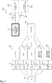
- Fig. 1 shows a message sequence diagram 100 illustrating common mobile-originated (MO) Short Message Service (SMS) and Fig. 2 shows a message sequence diagram 200 illustrating common mobile terminated (MT) Short Message Service.
- MO mobile-originated
- MT common mobile terminated
- the Short Message Service is realized by use of the Mobile Application Part (MAP) of the SS7 protocol, with Short Message protocol elements being transported across the network as fields within the MAP messages.
- the Short Message protocol itself is defined by 3GPP TS 23.040 for the Short Message Service - Point to Point (SMS-PP), and 3GPP TS 23.041 for the Cell Broadcast Service (CBS).
- SMS-PP Short Message Service - Point to Point
- CBS Cell Broadcast Service
- MAP procedures are defined for the control of the Short Message Service: Mobile Originated (MO) short message service transfer (as shown in Fig. 1 ); Mobile Terminated (MT) short message service transfer (as shown in Fig. 2 ); Short message alert procedure; Short message waiting data set procedure.
- MO Mobile Originated
- MT Mobile Terminated
- the handset 110 When the subscriber sends a Short Message, the handset 110 sends the text message over the air interface to the MSC/SGSN 111. Along with the actual text of the Short Message, the destination address of the SM and the address of the Short Message service center (SMSC) 120 are included, the latter taken from the handset's 110 configuration stored on the SIM card.
- SMSC Short Message service center
- the VMSC/SGSN invokes the MAP service package MAP_MO_FORWARD_SHORT_MESSAGE to send the text to the Interworking MSC 121 of the Service Center 120 whose address was provided by the handset 110.
- This service sends the mo-ForwardSM 102 MAP operation to the SMSC 120 identified in the SM submission from the handset 110, embedded within a Transaction Capabilities Application Part (TCAP) message, and transported over the core network using the Signalling Connection Control Part (SCCP).
- TCAP Transaction Capabilities Application Part
- the Interworking MSC 121 of the SMSC 120 on receipt of the MAP mo-ForwardSM message 102, passes the SMS-PP Application Protocol Data Unit (APDU) containing the text message 103 to the actual Service Center (SC) 122 of the SMSC 120 for storing, and subsequent "forwarding" (delivery) to the destination address and the SC 122 returns an acknowledgement 104 indicating success or failure.
- the Interworking MSC 121 On receipt of this submission status from the Service Center 122, the Interworking MSC 121 will send an appropriate indication 105 back to the VMSC/SGSN 111 of the sending subscriber. The message submission status 106 is then forwarded, over the air interface, to the subscriber's handset 110.
- the SMSC 120 When the SMSC 120 determines it needs to attempt to deliver a Short Message 201 to its destination, it will send the SMS-PP APDU containing the text message, the "B-Party" (destination phone number) and other details to the Gateway MSC (GMSC) 121 logical component on the SMSC 120.
- the GMSC 121 on receipt of this Short Message 201, needs to discover the location of the B-Party in order to be able to correctly deliver the text to the recipient (the term Gateway MSC, in this context, indicating an MSC that is obtaining routing information from the Home Location Register (HLR) 113).
- HLR Home Location Register
- the GMSC 121 invokes the MAP service package MAP_SEND_ROUTING_INFO_FOR_SM, which sends a sendRoutingIn-foForSM (SRI-for-SM 202) MAP message to the destination number's HLR 113, requesting their present location.
- This SRI-for-SM message 202 may be sent to an HLR 113 in the same network as the SMSC 120, or via an interconnect to an HLR 113 in a foreign PLMN, depending on which network the destination subscriber belongs to.
- the HLR 113 performs a database lookup to retrieve the B-Party's current location, and returns it in an acknowledgement message 203 to the SMSC's GMSC entity 121.
- the current location may be the MSC address the subscriber is currently roaming on, the SGSN address, or both.
- the HLR 113 may also return a failure, if it considers the destination to be unavailable for short messaging.
- the GMSC 121 will attempt to deliver the Short Message 201 to its recipient. This is done by invoking the MAP_MT_FORWARD_SHORT_MESSAGE service, which sends a MAP mt-ForwardSM message 204 to the address returned by the HLR 113, regardless of whether it is an MSC (Circuit Switched SMS delivery) or an SGSN (Packet Switched SMS delivery) 111.
- MSC Circuit Switched SMS delivery
- SGSN Packet Switched SMS delivery
- the VMSC 111 will request the information needed for it to deliver the Short Message 201 to its recipient by sending a Send_Info_for_MT_SMS message 205 to the VLR 112.
- the VLR 112 will then instigate a page request, or subscriber search, for the destination subscribers Mobile Subscriber ISDN Number (MSISDN) and return the result 206 to the VMSC 111. Since a typical deployment sees the VLR 112 being co-located with the MSC 111, this message flow is usually internal to the platform. Should the page or search for the subscriber fail, the VLR 112 will indicate the failure cause to the VMSC 111, which will abort the Short Message delivery procedure and return the failure to the SMSC 111.
- MSISDN Mobile Subscriber ISDN Number
- the VMSC 111 will then send to the SMSC indicating successful delivery 209.
- the GMSC 121 component of the SMSC 120 passes the result 210 of the delivery attempt to the Service Center 122.
- the delivered text message will be removed from the Store and Forward Engine (SFE) and, if requested, a delivery report sent to the text originator. If the delivery failed, the SMSC 120 invokes a retry procedure to periodically make further attempts at delivery; additionally, it may register with the HLR 113 to receive a notification when the B-Party becomes available for Short Message delivery in the future.
- SFE Store and Forward Engine
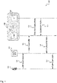
- Fig. 3 shows a block diagram of an exemplary communication system 300 including Universal Packet Signaling Messaging System (UPSMS) 340 according to the disclosure.
- USMS Universal Packet Signaling Messaging System
- the User Equipment (UE) 301 is connected to one or more access networks, e.g. a 2G/3G Radio network 311, a 4G Radio network 312, a 5G Radio network 313, a trusted access network 314 or an untrusted access network 315.
- the access networks are connected to respective core network nodes.
- the 2G/3G Radio network 311 is connected to a 2G/3G SGSN (Serving GPRS Support Node) node 321.
- the 4G Radio network 312 is connected to a MME (Mobile Management Entity) node 322.
- the 5G Radio network 313 is connected to an AMF (Access Management Function) 323.
- the trusted access network 314 is coupled to other trusted mobile or fixed packet core networks 324.
- the untrusted access network 315 is coupled to other untrusted mobile or fixed packet core networks 325.
- Each of the core network nodes 321, 322, 323, 324, 325 is connected to a HLR (Home Location Register) / HSS (Home Subscription Server) / cDB (common data base) 330, also denoted hereinafter as subscription and location server 330.
- the subscription and location server 330 is connected to the Universal Packet Signaling Messaging System (UPSMS) 340.
- UPSMS 340 is connected to legacy messaging systems 351 via interface 341, e.g. using Diameter or SS7.
- UPSMS 340 may be further connected to AS based IMS Messaging System 352 via interface 342, e.g. using SIP (Session Initiation Protocol).
- the UE (User Equipment) block 301 represents the user equipment or client terminal or mobile communication device which can be operated by the subscriber to initiate communication in the network, i.e. starting a communication (mobile originating, MO) or accepting (mobile terminating, MT).
- the UE 301 can also initiate communication without user interaction, e.g. it can be a machine terminal, e.g. for a car or a robot or other device.
- the radio access network nodes 311, 312, 313, 314, 315 represent the (radio) access network by which the UE 301 obtains access to the communication network.
- the interface between UE 301 and radio access network nodes 311, 312, 313, 314, 315 is either an air interface when the access network is a wireless network or wired when the access network is a wired network.
- the Access and Mobility Management Function (AMF) node 323 represents the access and mobility management function. It manages the access and mobility functions of the UE 301.
- the AMF 323 may also include network slice selection functionality. For wireless access, mobility management is not needed.
- the MME node 322 is the key control-node for the LTE access-network. It is responsible for idle mode UE (User Equipment) paging and tagging procedure including retransmissions. It is involved in the bearer activation/deactivation process and is also responsible for choosing the SGW for a UE at the initial attach and at time of intra-LTE handover involving Core Network (CN) node relocation.
- UE User Equipment
- the communication system 300 comprises one or more messaging systems 351, 352 for delivering messages based on a respective message signaling protocol, e.g. a legacy messaging system 351 delivering messages according to the SS7 signaling protocol or according to a Diameter protocol 341 and/or an Application Server (AS) based IMS (IP Multimedia Subsystem) messaging system 352 delivering messages according to a SIP (Session Initiation Protocol) protocol 342.
- the communication system 300 comprises one or more packet core networks, wherein each packet core network is designed according to a respective packet core network technology, e.g.
- the communication system 300 comprises a subscription and location server 330, configured to store for each subscriber of a plurality of subscribers associated with a corresponding User Equipment, UE: a subscriber identity; a subscriber location indicating in which packet core network of the plurality of packet core networks the subscriber is located; and an indication that a Universal Packet Signaling Messaging System (UPSMS) service is supported.
- UE User Equipment
- the communication system 300 comprises a UPSMS system 340, configured to extend a message received from one of the messaging systems 351, 352 based on a message signaling protocol extension that extends the message signaling protocol by including an indication that UPSMS is supported, and to forward the extended message to the subscription and location server 330.
- the subscription and location server 330 is configured to authenticate a subscriber based on the subscriber identity, and to identify for an authenticated subscriber, for whom the UPSMS service is supported, a packet core network of the plurality of packet core networks that is connected to the corresponding UE 301, based on the subscriber identity, and to deliver the extended message via the identified packet core network to the corresponding UE 301.
- the message signaling protocol extension may be based on control plane signaling.
- the message signaling protocol extension may be configured to add the indication that the UPSMS service is supported to the message received from one of the messaging systems and to encapsulate the message with the indication in the extended message.
- a format of the extended message is unified for the plurality of messaging systems.
- the subscription and location server 330 may be configured to deliver the extended message via control plane to the corresponding UE.
- the message signaling protocol extension may be based on a Diameter signaling protocol 341 or a service-based interface.
- the subscription and location server 330 may be configured to deliver the message via one of the following packet core networks to the UE 301: 2G/3G packet core network using SGSN 321, 4G packet core network using MME 322, 5G packet core network using AMF 323, Trusted mobile or fixed packet core network, Untrusted mobile or fixed packet core network, WLAN packet core network.
- the subscription and location server 330 may be a home subscription and location server of a roaming user of the UE 301.
- the UPSMS system 340 may be configured to provide firewall functionality to block a message based on a transport protocol of the message and an application protocol of the message.
- the subscription and location server 330 may be configured to determine a location of the UE 301 based on a paging functionality of the plurality of packet core networks, in particular based on a paging functionality of the packet core network of the plurality of packet core networks that is connected to the UE 301.
- the message content may be amongst others e.g. one of the following message types: SMS, IP-based packet, Unstructured data message, Over-the-Air (OTA) message e.g. for UE configuration purpose, Public warning message (PWS).
- SMS Short-the-Air
- IP-based packet Unstructured data message
- OTA Over-the-Air
- PWS Public warning message
- the UPSMS system 340 may be configured to: receive a message comprising a UE identifier of the UE; determine the subscription and location server associated with the UE based on the UE identifier; transmit a request to the subscription and location server requesting for an indication if UPSMS is supported for the UE, wherein the request message comprises the UE identifier; and forward the message to the subscription and location server responsive to an indication that UPSMS is supported for the UE.
- the subscription and location server 330 may be configured to: receive, from the UPSMS system (as provisioned to the subscription of the user), a request requesting for an indication if UPSMS is supported for the UE, wherein the request comprises a UE identifier of the UE; determine, based on the UE identifier, a subscription entry associated with the UE; retrieve, from the subscription entry, an indication indicating if UPSMS is supported for the UE and a packet core network identifier of the packet core network of the plurality of packet core networks that is connected to the UE; transmit, to the UPSMS system, a response to the request, the response comprising the retrieved indication; and forward the extended message from the UPSMS system to the packet core network corresponding to the retrieved packet core network identifier.
- Each of the packet core networks comprises a packet core network entity that is configured to: receive, from the UE, a registration request comprising a UE identifier of the UE and a request for a UPSMS subscription; register the UE for access to the corresponding packet core network based on the UE identifier and for a support of UPSMS; and transmit a registration message to the subscription and location server associated with the UE, wherein the registration message comprises the UE identifier of the UE and an indication that UPSMS is supported for the UE.
- the UE 301 may be configured to: transmit a registration request comprising the UE identifier of the UE and a request for a UPSMS subscription to the packet core network of the plurality of packet core networks that is connected to the UE; and transmit a message to the corresponding packet core network.
- the communication system 300 can deliver a short message, e.g. a terminating SMS, to a UE 301 without combined attach to a 2G/3G network and without the capability to receive IMS based messages.
- the device 301 may have a packet only attach to an e.g. 4G or 5G network 312, 313.
- the UPSMS 340 is able to deliver such a SMS message (or any other short message) together with the correlating HSS 330 and 4G/5G network 312, 313 to a UE 301 which is attached to a packet access (e.g. 4G, 5G).
- the HSS 330 knows the related packet core node (e.g. MME 322 or AMF 323) in charge serving the UE 301 and querying the UE location area.
- the MME 322 or AMF 323 uses network evolution native methods to page or locate the receiving UE 301. This efficient method doesn't require an establishment of a payload bearer and deployment of legacy core equipment is not necessary.
- a short message may be defined as a message with a limited number of bytes, e.g. between 150 bytes and 1500 bytes. Exemplary implementations of the UPSMS 340 and the subscription and location server 330 are described below with respect to Figures 6 and 7 .
- the communication system 300 with novel UPSMS 340 and novel subscription and location server 330 introduces new communication methods that allow operators to deliver secure and much more efficient all kind of small messages (e.g. SMS, IP based messaging, unstructured messages, OTA, public warning messages), using unified protocol extensions (e.g. Diameter extensions or Service Based Interface extensions), to a UE 301 connected to a packet core network (e.g. 4G, 5G, WLAN).
- a packet core network e.g. 4G, 5G, WLAN.
- Any kind of messages like OTA (over the air device configuration messages), unstructured messages (e.g. USSD), BLOB (Binary large objects), SMS, etc. are supported.
- IMS core network There is no need to deploy an IMS core network to enable the required SMS routing, e.g. for SMS delivery and sending the legacy nodes like e.g.
- the new unified signalling (e.g. Diameter extensions or Service Based Interface extensions) can support secure connection between an UE and/or between the packet core network elements (e.g. MME or AMF). Separate message transfer via control plane to the UE avoids payload traffic for messaging. This enables message transfer in scenarios for UEs with signalling only packet core network attach/access.
- a further advantage is, that the routing logic is independent from network/messaging platform and only uses the packet core network native routing and paging functions. This enables also interconnection for messaging services between operators with different network protocols/technologies in place e.g. SS7 and Diameter.
- the communication network 300 offers a central point for implementing a firewall for messaging which is able to correlate different transport protocols and applications.
- the communication system 300 illustrated in Fig. 3 provides the following advantages: A new network-based function to collect store, receive and forward messages (e.g. SMS, IP based messaging, unstructured messages, OTA messages, public warning messages).
- the communication system 300 provides new signalling between HSS to 4G or 5G or generic packet core (e.g. MME, AMF) which enables to send routing, delivery information and transparent message content together.
- the communication system 300 provides new DIAMETER based signalling design that allows unified transport of the content and delivery parameters from/to the HSS.
- the communication system 300 provides HSS extension to receive/transmit new Message request/response from UPSMS.
- the communication system 300 provides HSS extension to add the addresses of the packet core node where the terminating UE is located (e.g.
- the communication system 300 provides encryption of the signalling link and/or message parts.
- the communication system 300 provides an indicator to signal for HSS to the packet core, that universal packet control messaging is supported for a subscriber.
- the communication system 300 provides UE originated messages via the UPSMS.
- the communication system 300 provides transparent and non-transparent (cached/retried) delivery of messages for legacy messaging platforms as gateway.
- the communication system 300 provides "Forced" manufacture, operator or government organisation messages - independent from service subscription or exhausted data balances.
- the communication system 300 provides special charging for all types of messages transported via this new signalling.
- the communication system 300 provides common firewall function on protocol and application layer.
- the communication system 300 further provides standardized messages in future releases between DB and Network for message handling e.g.: Common paging and search function independent of access technology and location of the UE; Deliver message (attempt); Delivery status message (delivered, failed ...); Delivery processing state (pending, execution, implementation, upgrade, failed ...); Receive message; Receive status message; Receive processing state; Exchange service state (bidirectional).
- message handling e.g.: Common paging and search function independent of access technology and location of the UE; Deliver message (attempt); Delivery status message (delivered, failed ...); Delivery processing state (pending, execution, implementation, upgrade, failed ...); Receive message; Receive status message; Receive processing state; Exchange service state (bidirectional).
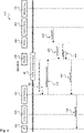
- Fig. 4 shows a message sequence diagram 400 illustrating an exemplary mobile terminating (MT) message transfer for short messages based on UPSMS 340 functionality according to the disclosure.
- MT mobile terminating
- Fig. 4 illustrates message transfer of a mobile terminating message 401 from a message source 412, e.g. a SMS service center as described above with respect to Fig. 2 or an IMS application server, to a corresponding UE 301.
- the message transfer is provided in a communication system 300 as described above with respect to Fig. 3 .
- the main components UE 301, Access Network A 410, Access Network B 411, HLR/HSS 330, UPSMS 340, message source 412 and message target 413 are shown.
- device registers 402 at access network B 411 e.g. one of the packet access networks 311, 321, 312, 322, 313, 323, 314, 324, 315, 325 depicted in Fig. 3 .
- Device registrations includes UPSMS subscription, i.e. subscription of the UE for the UPSMS service in the HLR/HSS (i.e. subscription and location server 330).
- access network B 411 transmits HLR/HSS location update message to HLR/HSS 330 (i.e. subscription and location server 330) to inform HLR/HSS 330 about the current location of the UE 301.
- UPSMS 330 transmits message MT 405 to HLR/HSS 330 which performs localization of the corresponding UE 301 to request for access network B 411 to which UE 301 is connected and transmits message MT 407 to access network B 411.
- Access network B 411 forwards message MT 408 to UE 301. Localization of the corresponding UE 301 may be performed according to the description with respect to Figures 6 and 7 .
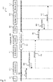
- Fig. 5 shows a message sequence diagram 500 illustrating an exemplary mobile originating (MO) message transfer for short messages based on UPSMS 340 functionality according to the disclosure.
- Fig. 5 illustrates message transfer of a mobile originating message 501 from the UE 301 to a message target 413, e.g. a SMS service center as described above with respect to Fig. 2 or an IMS application server.
- the message transfer is provided in a communication system 300 as described above with respect to Fig. 3 .
- the main components UE 301, Access Network A 410, Access Network B 411, HLR/HSS 330, UPSMS 340, message source 412 and message target 413 are shown.
- UE 301 transmits message MO (mobile originating) 502 to access network A 410 to which UE 301 is connected.
- Access network A 410 checks UPSMS subscription 503 and forwards message MO 504 to HLR/HSS 330 (i.e. subscription and location server 330) if the UE is subscribed to the UPSMS service. If a UE 301 is subscribed to the UPSMS service, the message MO can be directly forwarded to the novel subscription and location server 330, denoted herein as HLR/HSS 330.
- HLR/HSS 330 forwards message MO 505 to UPSMS 340 which performs CDR (call data record) generation 506.
- the CDR may generate a new entry in the UPSMS, e.g. including subscriber ID, location of UE and UPSMS support as described below with respect to Figure 7 .
- UPSMS 340 forwards message MO 507 to message target 513.
- Fig. 6 shows a block diagram of an exemplary UPSMS 340 according to the disclosure.
- the UPSMS 340 includes a processor 620 for processing a message 601 received from an input interface to an extended message 701 provided at an output interface.
- the message 601 may be received from a messaging system such as a legacy messaging system 351 or an AS based IMS messaging system 352 as shown in Fig. 3 .
- the message may be for example an SMS, an IP-based packet, an unstructured data message, an Over-the-Air (OTA) message, e.g. for UE configuration purpose, or a Public warning message (PWS).
- OTA Over-the-Air
- PWS Public warning message
- the processor 620 extends the message by including an UPSMS indication into the message, thereby generating the extended message 701.
- the UPSMS indication indicates that the novel UPSMS service is provided for the message 601, i.e.
- the processor 620 further includes a forwarding logic 622 for forwarding the extended message 701 to the subscription and location server 330.
- the forwarding logic 622 includes the address of the subscription and location server 330 or a route to the subscription and location server 330 into the message 601 in order to correctly transmit the extended message 701 to the subscription and location server 330.
- the UPSMS system 340 receives a message 601 comprising a UE identifier of the UE 301.
- the UPSMS 340 determines the subscription and location server 330 associated with the UE 301 based on the UE identifier.
- the UPSMS 340 transmits a request to the subscription and location server 330 requesting for an indication if UPSMS is supported for the UE 301, wherein the request message comprises the UE identifier.
- the UPSMS 340 generates the extended message 701 and forwards the extended message 701 to the subscription and location server 330 responsive to an indication that UPSMS is supported for the UE 301.
- a further functionality of the UPSMS 340 is to temporarily store and re-transmit messages such as the message 601 or the extended message 701, e.g. in the case of non-transmitted or erroneously transmitted messages or of temporarily non-reachable user terminal 301.
- Fig. 7 shows a block diagram of an exemplary subscription and location server 330 according to the disclosure.
- the subscription and location server 330 includes a memory 710 for storing for each subscriber of a plurality of subscribers associated with a corresponding UE: a subscriber identity (ID1, ID2, ..., IDn); a subscriber location (Location_1, Location_2, ..., Location n) indicating in which packet core network of the plurality of packet core networks the subscriber is located; and an indication that a Universal Packet Signaling Messaging System (UPSMS) service is supported.
- a subscriber identity ID1, ID2, ..., IDn
- a subscriber location Lication_1, Location_2, ..., Location n
- USMS Universal Packet Signaling Messaging System
- the subscription and location server 330 receives an extended message 701, e.g. as generated by the UPSMS 340 described above with respect to Fig. 6 .
- the subscription and location server 330 includes a processor 720 including authentication logic 721, checking logic 722 and identifying logic 723.
- the authentication logic 721 is configured to authenticate a subscriber based on the subscriber identity 711. I.e., the authentication logic 721 looks up the subscriber identity 711 received with the extended message 701 in the memory 710. If an entry exists in the memory 710 with the subscriber identity 711, the respective subscriber is authenticated.
- the checking logic 722 is configured to check for an authenticated subscriber in the memory 710, if the UPSMS service is supported for that subscriber.
- the identifying logic 723 identifies for an authenticated subscriber, for whom the UPSMS service is supported, a packet core network of the plurality of packet core networks that is connected to the corresponding UE 301 by looking up the location of the respective subscriber in the memory 710. Then the subscription and location server 330 delivers the extended message 701 via the identified packet core network to the corresponding UE 301.
- the subscription and location server 330 is configured to: receive, from the UPSMS system 340 as provisioned to the subscription of the user, a request requesting for an indication if UPSMS is supported for the UE 301, wherein the request comprises a UE identifier of the UE 301; determine, based on the UE identifier, a subscription entry associated with the UE 301; retrieve, from the subscription entry, an indication indicating if UPSMS is supported for the UE 301 and a packet core network identifier of the packet core network of the plurality of packet core networks that is connected to the UE 301; transmit, to the UPSMS system 340, a response to the request, the response comprising the retrieved indication; and forward the extended message 701 from the UPSMS system 340 to the packet core network corresponding to the retrieved packet core network identifier.
- Fig. 8 shows a schematic diagram illustrating an exemplary method 800 for short message transfer according to the disclosure.
- the method 800 can be used for transmitting a message in a communication system 300 comprising a plurality of messaging systems 351, 352 for delivering messages based on a respective message signaling protocol 341, 342; a plurality of packet core networks 311, 321, 312, 322, 313, 323, 314, 324, 315, 325, wherein each packet core network is designed according to a respective packet core network technology; a subscription and location server 330 for storing for each subscriber of a plurality of subscribers associated with a corresponding User Equipment, UE 301: a subscriber identity; a subscriber location indicating in which packet core network of the plurality of packet core networks the subscriber is located; and an indication that a Universal Packet Signaling Messaging System (UPSMS) service is supported; and a Universal Packet Signaling Messaging System (UPSMS) 340, e.g. as described above with respect to Fig. 3 .
- USMS Universal Packet Signaling Messaging System
- the method 800 comprises extending 801, by the UPSMS system 340, a message received from one of the messaging systems 351, 352 based on a message signaling protocol extension which extends the message signaling protocol by including an indication that UPSMS is supported, e.g. as described above with respect to Fig. 6 .
- the method 800 comprises forwarding 802, by the UPSMS system 340, the extended message to the subscription and location server 330, e.g. as described above with respect to Fig. 6 .
- the method 800 comprises identifying 803, by the subscription and location server 340, for an authenticated subscriber, for whom the UPSMS service is supported, a packet core network of the plurality of packet core networks that is connected to the corresponding UE, based on the subscriber identity, e.g. as described above with respect to Fig. 7 .
- the method 800 comprises delivering 804, by the subscription and location server 340, the extended message via the identified packet core network to the corresponding UE, e.g. as described above with respect to Fig. 7 .
- Another aspect of the invention is related to a computer program product comprising program code for performing the methods and procedures or the functionalities described above, when executed on a computer or a processor.
- the method may be implemented as program code that may be stored on a non-transitory computer medium.
- the computer program product may implement the techniques described above.
Landscapes
- Engineering & Computer Science (AREA)
- Computer Networks & Wireless Communication (AREA)
- Signal Processing (AREA)
- Computer Security & Cryptography (AREA)
- Computer Hardware Design (AREA)
- Computing Systems (AREA)
- General Engineering & Computer Science (AREA)
- Mobile Radio Communication Systems (AREA)
Description
- The invention relates to communication techniques based on Universal Packet Signaling Messaging System (UPSMS) for delivery of messages over packet signalling networks and an associated subscription and location server.
- For SMS (short message service) or message delivery over a packet core network an additional core network layer is required today. A MSC or IMS core platform (i.e. SMS over IP via IMS service) and the related registration of the UE with additional signalling is needed. To enable a seamless service interworking over different packet core network evolutions a complex combination of registration and interworking is needed. By phase out of older network elements (e.g. 2G/3G) or not congruent radio coverage rollouts, the service reachability or availability is decreasing. On the other hand, operators, manufactures, regulator or government organizations currently have no standardized method to exchange information (e.g. small messages) with UEs in an packet core and access network independent way.
-
US 2009/0318174 A1 describes an intelligent short message system that provides an integrated home location register and short message service center (HLR/SMSC). Upon receiving an indication from a mobile switching center (MSC) that an SMS message could not be delivered to a destination device, the integrated HLR/SMSC prevents further retries from being attempted until the destination device becomes available again. - It is the object of the present invention to provide a concept to solve the above-mentioned problems, in particular to provide a solution for improving the message delivery independent of the packet core network and independent from the access network and its evolutions.
- The foregoing and other objects are achieved by the subject matter of the independent claims. Further implementation forms are apparent from the dependent claims, the description and the figures.
- The disclosure is based on the concept of a novel signalling mechanism and introduction of a novel UPSMS network element, which delivers any kind of messages via control plane signalling, using unified protocol extensions (e.g. Diameter and NAS message extensions), to a UE connected via a access network to a packet core network (e.g. 5G and beyond, non 3GPP packet core networks). This enables a simple cost-efficient network deployment with no need to deploy legacy network function independent of the core network evolution (e.g. 5G and beyond). Additionally, for roaming and interconnection scenarios, a major simplification and cost-efficient deployment with such a unified packet-based message delivery can be achieved.
- The Universal Packet Switched Message System (UPSMS) can use any packet access and/or Core Network where a Subscriber can register via HSS (home subscription server) and/or other register databases. In such a network, a subscribed UE (user equipment) can receive and deliver small messages (e.g. SMS, IP based messaging, unstructured data, OTA (over-the-air) messages, public warning messages (PWS) with standardized packet core technology native paging and signalling capabilities and optionally via a secure transfer over the signalling layer (e.g. SMS, IP based messaging, unstructured messages, OTA messages). The system supports optimal message receive and message delivery including the message content via unified interfaces (e.g. DIAMETER protocol extensions or Service Based Interface extensions) between UPSMS and HSS/HLR and Packet core network elements (e.g. MME, AMF, etc.). The UPSMS supports interworking with legacy (e.g. SMS SC) and interworking with new messaging services (using application layer communication) as a gateway function with standard interfaces.
- The methods and systems presented below may be of various types. The individual elements described may be realized by hardware or software components, for example electronic components that can be manufactured by various technologies and include, for example, semiconductor chips, ASICs, microprocessors, digital signal processors, integrated electrical circuits, electro-optical circuits and/or passive components.
- The devices, systems and methods presented below are capable of transmitting information over a communication network. The term communication network or communication system refers to the technical infrastructure on which the transmission of signals takes place. The communication network essentially comprises the switching network in which the transmission and switching of the signals takes place between the stationary devices and platforms of the mobile radio network or fixed network, and the access network in which the transmission of the signals takes place between a network access device and the communication terminal. The communication network can comprise both components of a mobile radio network as well as components of a fixed network. In the mobile network, the access network is also referred to as an air interface and includes, for example, a base station (NodeB, eNodeB, radio cell) with mobile antenna to establish the communication to a communication terminal or user equipment as described above, for example, a mobile phone or a mobile device with mobile adapter or a machine terminal.
- According to a first aspect the invention relates to a communication system, comprising: a plurality of messaging systems for delivering messages based on a respective message signaling protocol; a plurality of packet core networks, wherein each packet core network is designed according to a respective packet core network technology; a subscription and location server, configured to store for each subscriber of a plurality of subscribers associated with a corresponding User Equipment, UE: a subscriber identity; a subscriber location indicating in which packet core network of the plurality of packet core networks the subscriber is located; and an indication that a Universal Packet Signaling Messaging System (UPSMS) service is supported; and a UPSMS system, configured to extend a message received from one of the messaging systems based on a message signaling protocol extension that extends the message signaling protocol by including an indication that UPSMS is supported, and to forward the extended message to the subscription and location server, wherein the subscription and location server is configured to authenticate a subscriber based on the subscriber identity, and to identify for an authenticated subscriber, for whom the UPSMS service is supported, a packet core network of the plurality of packet core networks that is connected to the corresponding UE, based on the subscriber identity, and to deliver the extended message via the identified packet core network to the corresponding UE.
- Such a communication system with UPSMS allows operators to deliver secure and much more efficient all kind of small messages (e.g. SMS, IP based messaging, unstructured messages, OTA, public warning messages), using unified protocol extensions (e.g. Diameter extensions or Service Based Interface extensions), to a UE connected to a packet core network (e.g. 4G, 5G, WLAN). The message transfer is agnostic to the access network and its evolution. The communication system provides support of any kind of messages like OTA (Device configuration messages), unstructured messages (e.g. USSD), BLOB (Binary large objects), SMS, etc. There is no need to deploy specific adaptations, e.g. for SMS delivery and sending the legacy nodes like e.g. GMSC or for new generation networks and the IMS core network to enable the required SMS routing. The new unified signalling (e.g. Diameter extensions or Service Based Interface extensions) can support secure connection between an UE and/or between the packet core network elements (e.g. MME, HSS, AMF). Hence, such a communication system simplifies the design of the overall communication network.
- In an exemplary implementation form of the communication system, the message signaling protocol extension is based on control plane signaling.
- This provides the advantage that the control plane can be used to deliver the message. Initiation or usage of the data plane can be avoided, thereby simplifying the design of the network, i.e. the communication system.
- In an exemplary implementation form of the communication system, the message signaling protocol extension is configured to add the indication that the UPSMS service is supported to the message received from one of the messaging systems and to encapsulate the message with the indication in the extended message, wherein a format of the extended message is unified for the plurality of messaging systems.
- This provides the advantage that messages from different messaging systems can be treated in a same manner. By encapsulating the message with the indication in the extended message, the extended message has the same format for all messages resulting from different messaging systems.
- In an exemplary implementation form of the communication system, the subscription and location server is configured to deliver the extended message via control plane to the corresponding UE.
- This provides the advantage that the subscription and location server can be designed without a complex data plane protocol for delivering different kind of data. The subscription and location server only has to provide the respective signaling protocol stack for delivering the message via control plane. This simplifies the design of the subscription and location server.
- Separate message transfer via control plane to the UE avoids payload traffic for messaging. This enables message transfer in scenarios for UEs with signalling only packet core network attach/access. A further advantage is, that the routing logic is independent from network/messaging platform and only uses the packet core network native routing and paging functions. This enables also interconnection for messaging services between operators with different network protocols/technologies in place e.g. SS7 and Diameter.
- In an exemplary implementation form of the communication system, the message signaling protocol extension is based on a Diameter signaling protocol or a service-based interface.
- This provides the advantage that existing implementations of messaging systems that are based on the Diameter signaling or a service-based interface (e.g. SIP) can be reused with the novel UPSMS feature because the message signaling protocol extension is based on the Diameter signaling protocol or a service-based protocol, e.g. SIP.
- In an exemplary implementation form of the communication system, the subscription and location server is configured to deliver the message via one of the following packet core networks to the UE: 2G/3G packet core network using SGSN, 4G packet core network using MME, 5G packet core network using AMF, Trusted mobile or fixed packet core network, Untrusted mobile or fixed packet core network, WLAN packet core network using a packet core network specific control element like e.g. an AAA.
- This provides the advantage that the communication system can interwork with a plurality of different packet core networks connecting the UE. When a new packet core network is developed, there is no need to change the design of the communication system.
- In an exemplary implementation form of the communication system, the subscription and location server is a home subscription and location server of a roaming user of the UE.
- This provides the advantage that the UPSMS can be applied for roaming scenarios.
- In an exemplary implementation form of the communication system, the UPSMS system is configured to provide firewall functionality to block a message based on a transport protocol of the message and an application protocol of the message.
- This provides the advantage that security of communication can be improved.
- In an exemplary implementation form of the communication system, the subscription and location server is configured to determine a location of the UE based on a paging functionality of the plurality of packet core networks, in particular based on a paging functionality of the packet core network of the plurality of packet core networks that is connected to the UE.
- This provides the advantage that the packet core network native paging functions can be efficiently exploited to determine the location of the UE.
- In an exemplary implementation form of the communication system, the message content is amongst others e.g. one of the following message types: SMS, IP-based packet, Unstructured data message, Over-the-Air (OTA) message e.g. for UE configuration purpose, Public warning message (PWS).
- This provides the advantage that the communication system can be used with different kind of messages, in particular short signaling messages.
- In an exemplary implementation form of the communication system, the UPSMS system is configured to: receive a message comprising a UE identifier of the UE; determine the subscription and location server associated with the UE based on the UE identifier; transmit a request to the subscription and location server requesting for an indication if UPSMS is supported for the UE, wherein the request message comprises the UE identifier; and forward the message to the subscription and location server responsive to an indication that UPSMS is supported for the UE.
- This provides the advantage that the UPSMS can efficiently determine the subscription and location server based on the UE identifier included in the message. The UPSMS can efficiently retrieve from the server if UPSMS is supported for that UE.
- In an exemplary implementation form of the communication system, the subscription and location server is configured to: receive, from the UPSMS system (as provisioned to the subscription of the user), a request requesting for an indication if UPSMS is supported for the UE, wherein the request comprises a UE identifier of the UE; determine, based on the UE identifier, a subscription entry associated with the UE; retrieve, from the subscription entry, an indication indicating if UPSMS is supported for the UE and a packet core network identifier of the packet core network of the plurality of packet core networks that is connected to the UE; transmit, to the UPSMS system, a response to the request, the response comprising the retrieved indication; and forward the extended message from the UPSMS system to the packet core network corresponding to the retrieved packet core network identifier.
- This provides the advantage that the subscription and location server can efficiently determine if UPSMS is supported for a UE based on its UE identifier.
- In an exemplary implementation form of the communication system, each of the packet core networks comprises a packet core network entity that is configured to: receive, from the UE, a registration request comprising a UE identifier of the UE and a request for a UPSMS subscription; register the UE for access to the corresponding packet core network based on the UE identifier and for a support of UPSMS; and transmit a registration message to the subscription and location server associated with the UE, wherein the registration message comprises the UE identifier of the UE and an indication that UPSMS is supported for the UE.
- This provides the advantage that registration for the UPSMS service can be efficiently performed by a respective packet core network.
- In an exemplary implementation form of the communication system, the communication system comprises the UE, wherein the UE is configured to: transmit a registration request comprising the UE identifier of the UE and a request for a UPSMS subscription to the packet core network of the plurality of packet core networks that is connected to the UE; and transmit a message to the corresponding packet core network.
- This provides the advantage that the UE can efficiently deal with the subscription to the novel UPSMS service.
- According to a second aspect, the invention relates to a method for transmitting a message in a communication system comprising a plurality of messaging systems for delivering messages based on a respective message signaling protocol; a plurality of packet core networks, wherein each packet core network is designed according to a respective packet core network technology; a subscription and location server for storing for each subscriber of a plurality of subscribers associated with a corresponding User Equipment, UE: a subscriber identity; a subscriber location indicating in which packet core network of the plurality of packet core networks the subscriber is located; and an indication that a Universal Packet Signaling Messaging System (UPSMS) service is supported; and a Universal Packet Signaling Messaging System (UPSMS), the method comprising: extending, by the UPSMS system, a message received from one of the messaging systems based on a message signaling protocol extension which extends the message signaling protocol by including an indication that UPSMS is supported; forwarding, by the UPSMS system, the extended message to the subscription and location server; identifying, by the subscription and location server, for an authenticated subscriber, for whom the UPSMS service is supported, a packet core network of the plurality of packet core networks that is connected to the corresponding UE, based on the subscriber identity; and delivering, by the subscription and location server, the extended message via the identified packet core network to the corresponding UE.
- Such a method using UPSMS allows operators to deliver secure and much more efficient all kind of small messages (e.g. SMS, IP based messaging, unstructured messages, OTA, public warning messages), using unified protocol extensions (e.g. Diameter extensions or Service Based Interface extensions), to a UE connected to a packet core network (e.g. 4G, 5G, WLAN). The message transfer is agnostic to the access network and its evolution. The method provides support of any kind of messages like OTA (Device configuration messages), unstructured messages (e.g. USSD), BLOB (Binary large objects), SMS, etc. There is no need to deploy specific adaptations, e.g. for SMS delivery and sending the legacy nodes like e.g. GMSC or for new generation networks and the IMS core network to enable the required SMS routing. The new unified signalling (e.g. Diameter extensions or Service Based Interface extensions) can support secure connection between an UE and/or between the packet core network elements (e.g. MME, HSS, AMF). Hence, by using such a method the design of the overall communication network can be simplified.
- According to a third aspect the invention relates to a computer program product comprising program code for performing the method according to the second aspect of the invention, when executed on a computer or a processor.
- Embodiments of the invention can be implemented in hardware and/or software.
- Further embodiments of the invention will be described with respect to the following figures, wherein:
-
Fig. 1 shows a message sequence diagram 100 illustrating common mobile-originated (MO) Short Message Service (SMS); -
Fig. 2 shows a message sequence diagram 200 illustrating common mobile terminated (MT) Short Message Service; -
Fig. 3 shows a block diagram of anexemplary communication system 300 including Universal Packet Signaling Messaging System (UPSMS) 340 according to the disclosure; -
Fig. 4 shows a message sequence diagram 400 illustrating an exemplary mobile terminating (MT) message transfer for short messages based onUPSMS 340 functionality according to the disclosure; -
Fig. 5 shows a message sequence diagram 500 illustrating an exemplary mobile originating (MO) message transfer for short messages based onUPSMS 340 functionality according to the disclosure; -
Fig. 6 shows a block diagram of anexemplary UPSMS 340 according to the disclosure; -
Fig. 7 shows a block diagram of an exemplary subscription andlocation server 330 according to the disclosure; -
Fig. 8 shows a schematic diagram illustrating anexemplary method 800 for short message transfer according to the disclosure. - In the following detailed description, reference is made to the accompanying drawings, which form part of the disclosure, and in which are shown, by way of illustration, specific aspects in which the present invention may be placed. It is understood that other aspects may be utilized and structural or logical changes may be made without departing from the scope of the present invention. The following detailed description, therefore, is not to be taken in a limiting sense, as the scope of the present invention is defined by the appended claims.
- For instance, it is understood that a disclosure in connection with a described method may also hold true for a corresponding device or system configured to perform the method and vice versa. For example, if a specific method step is described, a corresponding device may include a unit to perform the described method step, even if such unit is not explicitly described or illustrated in the figures. Further, it is understood that the features of the various exemplary aspects described herein may be combined with each other, unless specifically noted otherwise.
- In the following, network entities are described such as network access entities and core network entities. The network access entity enables access and mobility management in the communication network. Via the network access entity, communication terminals with their identity (UE ID) can register in the communication network and receive the permission to set up a communication connection. For example, in the 5G communication network, the network access entity may be an AMF (Access and Mobility Management Function) representing the access and mobility management function. This manages the access and mobility control. The AMF may also include network slice selection functionality. For wireless access, mobility management is not needed. The network access entity may be, for example, an MME (mobility management entity) in the 4G communication network. The MME is a network component of the LTE (Long Term Evolution) mobile radio standard, which performs the functions of paging to set up calls and generally communication links as well as signaling for control purposes. The MME forms the link between core network and access network. The MME manages the locations of all mobile communication terminals in the radio cells connected to it. In the LTE system, several cells are usually combined to form a tracking area. The management area of an MME can be divided into several tracking areas.
- The radio access network (RAN) is part of a mobile telecommunication system. It implements a radio access technology (RAT). Conceptually, it resides between a device such as a mobile phone, a computer, or any remotely controlled machine and provides connection with its core network (CN). Depending on the standard, mobile phones and other wireless connected devices are varyingly known as user equipment (UE), terminal equipment, mobile station (MS), etc. RAN functionality is typically provided by a RAN entity, e.g. a silicon chip, residing in both the core network as well as the user equipment. Examples of radio access network types are GERAN, the GSM radio access network including EDGE packet radio services, UTRAN, the UMTS radio access network, E-UTRAN, the LTE radio access network and the 5G RAN. The RAN entity can for example include a base station, e.g. a NodeB or and eNodeB or a 5G capable radio cell.
- The network access entity further provides the technical function of first establishing a security relationship with a previously unknown security device, in order to then be able to install security elements (keys) in the device itself and in the network application function (NAF) of the network access function. For example, the Diameter and Hypertext Transfer Protocol (http) protocols can be used. For example, SOAP may be used between BSF and NAF instead of diameter.
- Involved in the maintenance of such a generic security relationship are the following functional elements: terminal, e.g. a mobile phone, i.e. User Equipment (UE), which wants to use a particular service, application server that provides the service, e.g. for Mobile TV, VoLTE, VoIP, FTP data transfer, media streaming, Internet browsing, etc., Network Application Function (NAF), the network access entity itself, which establishes a security relationship between UE and NAF and a database of the home network, e.g. HSS Home Subscriber Server (HSS) or UDR, unified data repository of the (mobile) network provider, which manages the respective user-specific profiles of its terminal users.
- The network access entity network access feature is consulted by the application server (NAF) after a terminal has requested service access from it. Since the application server does not yet know the terminal at this time, it first refers this to the network access function. The terminal and the network access function now authenticate to each other; this can be done, for example, by means of the AKA protocol (Authentication and Key Agreement) and by inquiring the network access function to the Home Subscriber Server (HSS) or the UDR database of the home network. Subsequently, the network access function and the terminal (UE) agree on a session key to be used for encrypted data exchange with the application server (NAF). If the terminal now again turns to the application server, it can obtain both the session key and subscriber-specific data from the network access function and start the data exchange with the terminal (UE). The appropriate session keys are used for cryptographic protection.
-
Fig. 1 shows a message sequence diagram 100 illustrating common mobile-originated (MO) Short Message Service (SMS) andFig. 2 shows a message sequence diagram 200 illustrating common mobile terminated (MT) Short Message Service. - The Short Message Service is realized by use of the Mobile Application Part (MAP) of the SS7 protocol, with Short Message protocol elements being transported across the network as fields within the MAP messages. The Short Message protocol itself is defined by 3GPP TS 23.040 for the Short Message Service - Point to Point (SMS-PP), and 3GPP TS 23.041 for the Cell Broadcast Service (CBS). Four MAP procedures are defined for the control of the Short Message Service: Mobile Originated (MO) short message service transfer (as shown in
Fig. 1 ); Mobile Terminated (MT) short message service transfer (as shown inFig. 2 ); Short message alert procedure; Short message waiting data set procedure. - When the subscriber sends a Short Message, the
handset 110 sends the text message over the air interface to the MSC/SGSN 111. Along with the actual text of the Short Message, the destination address of the SM and the address of the Short Message service center (SMSC) 120 are included, the latter taken from the handset's 110 configuration stored on the SIM card. - Regardless of the air interface technology, the VMSC/SGSN invokes the MAP service package MAP_MO_FORWARD_SHORT_MESSAGE to send the text to the
Interworking MSC 121 of theService Center 120 whose address was provided by thehandset 110. This service sends the mo-ForwardSM 102 MAP operation to theSMSC 120 identified in the SM Submission from thehandset 110, embedded within a Transaction Capabilities Application Part (TCAP) message, and transported over the core network using the Signalling Connection Control Part (SCCP). - The
Interworking MSC 121 of theSMSC 120, on receipt of the MAP mo-ForwardSM message 102, passes the SMS-PP Application Protocol Data Unit (APDU) containing thetext message 103 to the actual Service Center (SC) 122 of theSMSC 120 for storing, and subsequent "forwarding" (delivery) to the destination address and theSC 122 returns anacknowledgement 104 indicating success or failure. On receipt of this submission status from theService Center 122, theInterworking MSC 121 will send anappropriate indication 105 back to the VMSC/SGSN 111 of the sending subscriber. Themessage submission status 106 is then forwarded, over the air interface, to the subscriber'shandset 110. - When the
SMSC 120 determines it needs to attempt to deliver aShort Message 201 to its destination, it will send the SMS-PP APDU containing the text message, the "B-Party" (destination phone number) and other details to the Gateway MSC (GMSC) 121 logical component on theSMSC 120. TheGMSC 121, on receipt of thisShort Message 201, needs to discover the location of the B-Party in order to be able to correctly deliver the text to the recipient (the term Gateway MSC, in this context, indicating an MSC that is obtaining routing information from the Home Location Register (HLR) 113). To do this, theGMSC 121 invokes the MAP service package MAP_SEND_ROUTING_INFO_FOR_SM, which sends a sendRoutingIn-foForSM (SRI-for-SM 202) MAP message to the destination number'sHLR 113, requesting their present location. This SRI-for-SM message 202 may be sent to anHLR 113 in the same network as theSMSC 120, or via an interconnect to anHLR 113 in a foreign PLMN, depending on which network the destination subscriber belongs to. - The
HLR 113 performs a database lookup to retrieve the B-Party's current location, and returns it in anacknowledgement message 203 to the SMSC'sGMSC entity 121. The current location may be the MSC address the subscriber is currently roaming on, the SGSN address, or both. TheHLR 113 may also return a failure, if it considers the destination to be unavailable for short messaging. - Having obtained the routing information from the
HLR 113, theGMSC 121 will attempt to deliver theShort Message 201 to its recipient. This is done by invoking the MAP_MT_FORWARD_SHORT_MESSAGE service, which sends a MAP mt-ForwardSM message 204 to the address returned by theHLR 113, regardless of whether it is an MSC (Circuit Switched SMS delivery) or an SGSN (Packet Switched SMS delivery) 111. - The
VMSC 111 will request the information needed for it to deliver theShort Message 201 to its recipient by sending aSend_Info_for_MT_SMS message 205 to theVLR 112. TheVLR 112 will then instigate a page request, or subscriber search, for the destination subscribers Mobile Subscriber ISDN Number (MSISDN) and return theresult 206 to theVMSC 111. Since a typical deployment sees theVLR 112 being co-located with theMSC 111, this message flow is usually internal to the platform. Should the page or search for the subscriber fail, theVLR 112 will indicate the failure cause to theVMSC 111, which will abort the Short Message delivery procedure and return the failure to theSMSC 111. If the page of thehandset 110 was successful andShort Message delivery 207 was sent andDelivery Ack 208 fromhandset 110 received, theVMSC 111 will then send to the SMSC indicatingsuccessful delivery 209. TheGMSC 121 component of theSMSC 120 passes theresult 210 of the delivery attempt to theService Center 122. In the case of successful delivery, the delivered text message will be removed from the Store and Forward Engine (SFE) and, if requested, a delivery report sent to the text originator. If the delivery failed, theSMSC 120 invokes a retry procedure to periodically make further attempts at delivery; additionally, it may register with theHLR 113 to receive a notification when the B-Party becomes available for Short Message delivery in the future. -
Fig. 3 shows a block diagram of anexemplary communication system 300 including Universal Packet Signaling Messaging System (UPSMS) 340 according to the disclosure. - The User Equipment (UE) 301 is connected to one or more access networks, e.g. a 2G/
3G Radio network 311, a4G Radio network 312, a5G Radio network 313, a trustedaccess network 314 or anuntrusted access network 315. The access networks are connected to respective core network nodes. The 2G/3G Radio network 311 is connected to a 2G/3G SGSN (Serving GPRS Support Node)node 321. The4G Radio network 312 is connected to a MME (Mobile Management Entity)node 322. The5G Radio network 313 is connected to an AMF (Access Management Function) 323. The trustedaccess network 314 is coupled to other trusted mobile or fixed packet core networks 324. Theuntrusted access network 315 is coupled to other untrusted mobile or fixed packet core networks 325. Each of thecore network nodes location server 330. The subscription andlocation server 330 is connected to the Universal Packet Signaling Messaging System (UPSMS) 340.UPSMS 340 is connected tolegacy messaging systems 351 viainterface 341, e.g. using Diameter or SS7.UPSMS 340 may be further connected to AS basedIMS Messaging System 352 viainterface 342, e.g. using SIP (Session Initiation Protocol). - The UE (User Equipment) block 301 represents the user equipment or client terminal or mobile communication device which can be operated by the subscriber to initiate communication in the network, i.e. starting a communication (mobile originating, MO) or accepting (mobile terminating, MT). The
UE 301 can also initiate communication without user interaction, e.g. it can be a machine terminal, e.g. for a car or a robot or other device. - The radio
access network nodes UE 301 obtains access to the communication network. The interface betweenUE 301 and radioaccess network nodes - The Access and Mobility Management Function (AMF)
node 323 represents the access and mobility management function. It manages the access and mobility functions of theUE 301. TheAMF 323 may also include network slice selection functionality. For wireless access, mobility management is not needed. - The
MME node 322 is the key control-node for the LTE access-network. It is responsible for idle mode UE (User Equipment) paging and tagging procedure including retransmissions. It is involved in the bearer activation/deactivation process and is also responsible for choosing the SGW for a UE at the initial attach and at time of intra-LTE handover involving Core Network (CN) node relocation. - In the following, an exemplary functionality of the
communication system 300 is described. Thecommunication system 300 comprises one ormore messaging systems legacy messaging system 351 delivering messages according to the SS7 signaling protocol or according to aDiameter protocol 341 and/or an Application Server (AS) based IMS (IP Multimedia Subsystem)messaging system 352 delivering messages according to a SIP (Session Initiation Protocol)protocol 342. Thecommunication system 300 comprises one or more packet core networks, wherein each packet core network is designed according to a respective packet core network technology, e.g. 2G/3G packet core network technology including 2G/3G radio 3G SGSN 321, or e.g. 4G packet core network technology including4G radio 312 andMME 322, or e.g. 5G packet core network technology including5G radio 313 andAMF 323, or e.g. other packet core network technology. Thecommunication system 300 comprises a subscription andlocation server 330, configured to store for each subscriber of a plurality of subscribers associated with a corresponding User Equipment, UE: a subscriber identity; a subscriber location indicating in which packet core network of the plurality of packet core networks the subscriber is located; and an indication that a Universal Packet Signaling Messaging System (UPSMS) service is supported. Thecommunication system 300 comprises aUPSMS system 340, configured to extend a message received from one of themessaging systems location server 330. The subscription andlocation server 330 is configured to authenticate a subscriber based on the subscriber identity, and to identify for an authenticated subscriber, for whom the UPSMS service is supported, a packet core network of the plurality of packet core networks that is connected to thecorresponding UE 301, based on the subscriber identity, and to deliver the extended message via the identified packet core network to thecorresponding UE 301. - The message signaling protocol extension may be based on control plane signaling. The message signaling protocol extension may be configured to add the indication that the UPSMS service is supported to the message received from one of the messaging systems and to encapsulate the message with the indication in the extended message. A format of the extended message is unified for the plurality of messaging systems.
- The subscription and
location server 330 may be configured to deliver the extended message via control plane to the corresponding UE. The message signaling protocol extension may be based on aDiameter signaling protocol 341 or a service-based interface. - The subscription and
location server 330 may be configured to deliver the message via one of the following packet core networks to the UE 301: 2G/3G packet corenetwork using SGSN 321, 4G packet corenetwork using MME network using AMF 323, Trusted mobile or fixed packet core network, Untrusted mobile or fixed packet core network, WLAN packet core network. - The subscription and
location server 330 may be a home subscription and location server of a roaming user of theUE 301. - The
UPSMS system 340 may be configured to provide firewall functionality to block a message based on a transport protocol of the message and an application protocol of the message. - The subscription and
location server 330 may be configured to determine a location of theUE 301 based on a paging functionality of the plurality of packet core networks, in particular based on a paging functionality of the packet core network of the plurality of packet core networks that is connected to theUE 301. - The message content may be amongst others e.g. one of the following message types: SMS, IP-based packet, Unstructured data message, Over-the-Air (OTA) message e.g. for UE configuration purpose, Public warning message (PWS).
- The
UPSMS system 340 may be configured to: receive a message comprising a UE identifier of the UE; determine the subscription and location server associated with the UE based on the UE identifier; transmit a request to the subscription and location server requesting for an indication if UPSMS is supported for the UE, wherein the request message comprises the UE identifier; and forward the message to the subscription and location server responsive to an indication that UPSMS is supported for the UE. - The subscription and
location server 330 may be configured to: receive, from the UPSMS system (as provisioned to the subscription of the user), a request requesting for an indication if UPSMS is supported for the UE, wherein the request comprises a UE identifier of the UE; determine, based on the UE identifier, a subscription entry associated with the UE; retrieve, from the subscription entry, an indication indicating if UPSMS is supported for the UE and a packet core network identifier of the packet core network of the plurality of packet core networks that is connected to the UE; transmit, to the UPSMS system, a response to the request, the response comprising the retrieved indication; and forward the extended message from the UPSMS system to the packet core network corresponding to the retrieved packet core network identifier. - Each of the packet core networks comprises a packet core network entity that is configured to: receive, from the UE, a registration request comprising a UE identifier of the UE and a request for a UPSMS subscription; register the UE for access to the corresponding packet core network based on the UE identifier and for a support of UPSMS; and transmit a registration message to the subscription and location server associated with the UE, wherein the registration message comprises the UE identifier of the UE and an indication that UPSMS is supported for the UE.
- The
UE 301 may be configured to: transmit a registration request comprising the UE identifier of the UE and a request for a UPSMS subscription to the packet core network of the plurality of packet core networks that is connected to the UE; and transmit a message to the corresponding packet core network. - The
communication system 300 can deliver a short message, e.g. a terminating SMS, to aUE 301 without combined attach to a 2G/3G network and without the capability to receive IMS based messages. Thedevice 301 may have a packet only attach to an e.g. 4G or5G network UPSMS 340 is able to deliver such a SMS message (or any other short message) together with the correlatingHSS 330 and 4G/5G network UE 301 which is attached to a packet access (e.g. 4G, 5G). TheHSS 330 knows the related packet core node (e.g. MME 322 or AMF 323) in charge serving theUE 301 and querying the UE location area. TheMME 322 orAMF 323 uses network evolution native methods to page or locate the receivingUE 301. This efficient method doesn't require an establishment of a payload bearer and deployment of legacy core equipment is not necessary. In this disclosure a short message may be defined as a message with a limited number of bytes, e.g. between 150 bytes and 1500 bytes. Exemplary implementations of theUPSMS 340 and the subscription andlocation server 330 are described below with respect toFigures 6 and7 . - The
communication system 300 withnovel UPSMS 340 and novel subscription andlocation server 330 introduces new communication methods that allow operators to deliver secure and much more efficient all kind of small messages (e.g. SMS, IP based messaging, unstructured messages, OTA, public warning messages), using unified protocol extensions (e.g. Diameter extensions or Service Based Interface extensions), to aUE 301 connected to a packet core network (e.g. 4G, 5G, WLAN). Any kind of messages like OTA (over the air device configuration messages), unstructured messages (e.g. USSD), BLOB (Binary large objects), SMS, etc. are supported. There is no need to deploy an IMS core network to enable the required SMS routing, e.g. for SMS delivery and sending the legacy nodes like e.g. GMSC or for new generation networks. The new unified signalling (e.g. Diameter extensions or Service Based Interface extensions) can support secure connection between an UE and/or between the packet core network elements (e.g. MME or AMF). Separate message transfer via control plane to the UE avoids payload traffic for messaging. This enables message transfer in scenarios for UEs with signalling only packet core network attach/access. A further advantage is, that the routing logic is independent from network/messaging platform and only uses the packet core network native routing and paging functions. This enables also interconnection for messaging services between operators with different network protocols/technologies in place e.g. SS7 and Diameter. Thecommunication network 300 offers a central point for implementing a firewall for messaging which is able to correlate different transport protocols and applications. - The
communication system 300 illustrated inFig. 3 provides the following advantages: A new network-based function to collect store, receive and forward messages (e.g. SMS, IP based messaging, unstructured messages, OTA messages, public warning messages). Thecommunication system 300 provides new signalling between HSS to 4G or 5G or generic packet core (e.g. MME, AMF) which enables to send routing, delivery information and transparent message content together. Thecommunication system 300 provides new DIAMETER based signalling design that allows unified transport of the content and delivery parameters from/to the HSS. Thecommunication system 300 provides HSS extension to receive/transmit new Message request/response from UPSMS. Thecommunication system 300 provides HSS extension to add the addresses of the packet core node where the terminating UE is located (e.g. MME or AMF) and construct a new message which is used to deliver the message content to the related packet core node (e.g. to MME or AMF). Thecommunication system 300 provides encryption of the signalling link and/or message parts. Thecommunication system 300 provides an indicator to signal for HSS to the packet core, that universal packet control messaging is supported for a subscriber. Thecommunication system 300 provides UE originated messages via the UPSMS. Thecommunication system 300 provides transparent and non-transparent (cached/retried) delivery of messages for legacy messaging platforms as gateway. Thecommunication system 300 provides "Forced" manufacture, operator or government organisation messages - independent from service subscription or exhausted data balances. Thecommunication system 300 provides special charging for all types of messages transported via this new signalling. Thecommunication system 300 provides common firewall function on protocol and application layer. Thecommunication system 300 further provides standardized messages in future releases between DB and Network for message handling e.g.: Common paging and search function independent of access technology and location of the UE; Deliver message (attempt); Delivery status message (delivered, failed ...); Delivery processing state (pending, execution, implementation, upgrade, failed ...); Receive message; Receive status message; Receive processing state; Exchange service state (bidirectional). -
Fig. 4 shows a message sequence diagram 400 illustrating an exemplary mobile terminating (MT) message transfer for short messages based onUPSMS 340 functionality according to the disclosure. -
Fig. 4 illustrates message transfer of a mobile terminatingmessage 401 from amessage source 412, e.g. a SMS service center as described above with respect toFig. 2 or an IMS application server, to acorresponding UE 301. The message transfer is provided in acommunication system 300 as described above with respect toFig. 3 . Themain components UE 301,Access Network A 410,Access Network B 411, HLR/HSS 330,UPSMS 340,message source 412 andmessage target 413 are shown. - In the beginning, device registers 402 at
access network B 411, e.g. one of thepacket access networks Fig. 3 . Device registrations includes UPSMS subscription, i.e. subscription of the UE for the UPSMS service in the HLR/HSS (i.e. subscription and location server 330). Then,access network B 411 transmits HLR/HSS location update message to HLR/HSS 330 (i.e. subscription and location server 330) to inform HLR/HSS 330 about the current location of theUE 301. Whenmessage source 412 transmits message MT (mobile terminated) 404 toUPSMS 330,UPSMS 330 transmitsmessage MT 405 to HLR/HSS 330 which performs localization of thecorresponding UE 301 to request foraccess network B 411 to whichUE 301 is connected and transmitsmessage MT 407 to accessnetwork B 411.Access network B 411forwards message MT 408 toUE 301. Localization of thecorresponding UE 301 may be performed according to the description with respect toFigures 6 and7 . -
Fig. 5 shows a message sequence diagram 500 illustrating an exemplary mobile originating (MO) message transfer for short messages based onUPSMS 340 functionality according to the disclosure. -
Fig. 5 illustrates message transfer of a mobile originatingmessage 501 from theUE 301 to amessage target 413, e.g. a SMS service center as described above with respect toFig. 2 or an IMS application server. The message transfer is provided in acommunication system 300 as described above with respect toFig. 3 . Themain components UE 301,Access Network A 410,Access Network B 411, HLR/HSS 330,UPSMS 340,message source 412 andmessage target 413 are shown. -
UE 301 transmits message MO (mobile originating) 502 to accessnetwork A 410 to whichUE 301 is connected.Access network A 410 checksUPSMS subscription 503 andforwards message MO 504 to HLR/HSS 330 (i.e. subscription and location server 330) if the UE is subscribed to the UPSMS service. If aUE 301 is subscribed to the UPSMS service, the message MO can be directly forwarded to the novel subscription andlocation server 330, denoted herein as HLR/HSS 330. HLR/HSS 330forwards message MO 505 toUPSMS 340 which performs CDR (call data record)generation 506. The CDR may generate a new entry in the UPSMS, e.g. including subscriber ID, location of UE and UPSMS support as described below with respect toFigure 7 . ThenUPSMS 340forwards message MO 507 tomessage target 513. -
Fig. 6 shows a block diagram of anexemplary UPSMS 340 according to the disclosure. - The
UPSMS 340 includes aprocessor 620 for processing amessage 601 received from an input interface to anextended message 701 provided at an output interface. Themessage 601 may be received from a messaging system such as alegacy messaging system 351 or an AS basedIMS messaging system 352 as shown inFig. 3 . The message may be for example an SMS, an IP-based packet, an unstructured data message, an Over-the-Air (OTA) message, e.g. for UE configuration purpose, or a Public warning message (PWS). Theprocessor 620 extends the message by including an UPSMS indication into the message, thereby generating theextended message 701. The UPSMS indication indicates that the novel UPSMS service is provided for themessage 601, i.e. that themessage 601 may be directly forwarded to the subscription andlocation server 330 which knows the correct routing (i.e. the packet core network of the corresponding UE) for the message. Theprocessor 620 further includes a forwardinglogic 622 for forwarding theextended message 701 to the subscription andlocation server 330. For example, the forwardinglogic 622 includes the address of the subscription andlocation server 330 or a route to the subscription andlocation server 330 into themessage 601 in order to correctly transmit theextended message 701 to the subscription andlocation server 330. - In an exemplary implementation, the
UPSMS system 340 receives amessage 601 comprising a UE identifier of theUE 301. TheUPSMS 340 determines the subscription andlocation server 330 associated with theUE 301 based on the UE identifier. TheUPSMS 340 transmits a request to the subscription andlocation server 330 requesting for an indication if UPSMS is supported for theUE 301, wherein the request message comprises the UE identifier. TheUPSMS 340 generates theextended message 701 and forwards theextended message 701 to the subscription andlocation server 330 responsive to an indication that UPSMS is supported for theUE 301. - A further functionality of the
UPSMS 340 is to temporarily store and re-transmit messages such as themessage 601 or theextended message 701, e.g. in the case of non-transmitted or erroneously transmitted messages or of temporarilynon-reachable user terminal 301. -
Fig. 7 shows a block diagram of an exemplary subscription andlocation server 330 according to the disclosure. - The subscription and
location server 330 includes amemory 710 for storing for each subscriber of a plurality of subscribers associated with a corresponding UE: a subscriber identity (ID1, ID2, ..., IDn); a subscriber location (Location_1, Location_2, ..., Location n) indicating in which packet core network of the plurality of packet core networks the subscriber is located; and an indication that a Universal Packet Signaling Messaging System (UPSMS) service is supported. - The subscription and
location server 330 receives anextended message 701, e.g. as generated by theUPSMS 340 described above with respect toFig. 6 . - The subscription and
location server 330 includes aprocessor 720 includingauthentication logic 721, checkinglogic 722 and identifyinglogic 723. Theauthentication logic 721 is configured to authenticate a subscriber based on thesubscriber identity 711. I.e., theauthentication logic 721 looks up thesubscriber identity 711 received with theextended message 701 in thememory 710. If an entry exists in thememory 710 with thesubscriber identity 711, the respective subscriber is authenticated. The checkinglogic 722 is configured to check for an authenticated subscriber in thememory 710, if the UPSMS service is supported for that subscriber. The identifyinglogic 723 identifies for an authenticated subscriber, for whom the UPSMS service is supported, a packet core network of the plurality of packet core networks that is connected to thecorresponding UE 301 by looking up the location of the respective subscriber in thememory 710. Then the subscription andlocation server 330 delivers theextended message 701 via the identified packet core network to thecorresponding UE 301. - In an exemplary implementation, the subscription and
location server 330 is configured to: receive, from theUPSMS system 340 as provisioned to the subscription of the user, a request requesting for an indication if UPSMS is supported for theUE 301, wherein the request comprises a UE identifier of theUE 301; determine, based on the UE identifier, a subscription entry associated with theUE 301; retrieve, from the subscription entry, an indication indicating if UPSMS is supported for theUE 301 and a packet core network identifier of the packet core network of the plurality of packet core networks that is connected to theUE 301; transmit, to theUPSMS system 340, a response to the request, the response comprising the retrieved indication; and forward theextended message 701 from theUPSMS system 340 to the packet core network corresponding to the retrieved packet core network identifier. -
Fig. 8 shows a schematic diagram illustrating anexemplary method 800 for short message transfer according to the disclosure. - The
method 800 can be used for transmitting a message in acommunication system 300 comprising a plurality ofmessaging systems message signaling protocol packet core networks location server 330 for storing for each subscriber of a plurality of subscribers associated with a corresponding User Equipment, UE 301: a subscriber identity; a subscriber location indicating in which packet core network of the plurality of packet core networks the subscriber is located; and an indication that a Universal Packet Signaling Messaging System (UPSMS) service is supported; and a Universal Packet Signaling Messaging System (UPSMS) 340, e.g. as described above with respect toFig. 3 . - The
method 800 comprises extending 801, by theUPSMS system 340, a message received from one of themessaging systems Fig. 6 . - The
method 800 comprises forwarding 802, by theUPSMS system 340, the extended message to the subscription andlocation server 330, e.g. as described above with respect toFig. 6 . - The
method 800 comprises identifying 803, by the subscription andlocation server 340, for an authenticated subscriber, for whom the UPSMS service is supported, a packet core network of the plurality of packet core networks that is connected to the corresponding UE, based on the subscriber identity, e.g. as described above with respect toFig. 7 . - The
method 800 comprises delivering 804, by the subscription andlocation server 340, the extended message via the identified packet core network to the corresponding UE, e.g. as described above with respect toFig. 7 . - Another aspect of the invention is related to a computer program product comprising program code for performing the methods and procedures or the functionalities described above, when executed on a computer or a processor. The method may be implemented as program code that may be stored on a non-transitory computer medium. The computer program product may implement the techniques described above.
- While a particular feature or aspect of the disclosure may have been disclosed with respect to only one of several implementations or embodiments, such feature or aspect may be combined with one or more other features or aspects of the other implementations or embodiments as may be desired and advantageous for any given or particular application. Furthermore, to the extent that the terms "include", "have", "with", or other variants thereof are used in either the detailed description or the claims, such terms are intended to be inclusive in a manner similar to the term "comprise". Also, the terms "exemplary", "for example" and "e.g." are merely meant as an example, rather than the best or optimal. The terms "coupled" and "connected", along with derivatives may have been used. It should be understood that these terms may have been used to indicate that two elements cooperate or interact with each other regardless whether they are in direct physical or electrical contact, or they are not in direct contact with each other.
- Although specific aspects have been illustrated and described herein, it will be appreciated by those of ordinary skill in the art that a variety of alternate and/or equivalent implementations may be substituted for the specific aspects shown and described without departing from the scope of the present disclosure. This application is intended to cover any adaptations or variations of the specific aspects discussed herein.
- Although the elements in the following claims are recited in a particular sequence, unless the claim recitations otherwise imply a particular sequence for implementing some or all of those elements, those elements are not necessarily intended to be limited to being implemented in that particular sequence.
- Many alternatives, modifications, and variations will be apparent to those skilled in the art in light of the above teachings. Of course, those skilled in the art readily recognize that there are numerous applications of the invention beyond those described herein. While the present invention has been described with reference to one or more particular embodiments, those skilled in the art recognize that many changes may be made thereto without departing from the scope of the present invention. It is therefore to be understood that within the scope of the appended claims, the invention may be practiced otherwise than as specifically described herein.
Claims (14)
- A communication system (300), comprising:a plurality of messaging systems (351, 352) for delivering messages based on a respective message signaling protocol (341, 342);a plurality of packet core networks (311, 321, 312, 322, 313, 323, 314, 324, 315, 325), wherein each packet core network is designed according to a respective packet core network technology;a subscription and location server (330), configured to store for each subscriber of a plurality of subscribers associated with a corresponding User Equipment, UE (301):a subscriber identity;a subscriber location indicating in which packet core network of the plurality of packet core networks the subscriber is located; andan indication that a Universal Packet Signaling Messaging System, UPSMS, service is supported; anda UPSMS system (340), configured to extend a message received from one of the messaging systems (351, 352) based on a message signaling protocol extension that extends the message signaling protocol (341, 342) by including an indication that the UPSMS service is supported for a respective subscriber, and to forward the extended message to the subscription and location server (330),wherein the subscription and location server (330) is configured to authenticate a subscriber based on the subscriber identity, and to identify for an authenticated subscriber, for whom the UPSMS service is supported, a packet core network of the plurality of packet core networks that is connected to the corresponding UE (301), based on the subscriber identity, and to deliver the extended message via the identified packet core network to the corresponding UE (301).
- The communication system (300) of claim 1,
wherein the message signaling protocol extension is based on control plane signaling. - The communication system (300) of claim 1 or 2,
wherein the message signaling protocol extension is configured to add the indication that the UPSMS service is supported to the message received from one of the messaging systems (351, 352) and to encapsulate the message with the indication in the extended message, wherein a format of the extended message is unified for the plurality of messaging systems (351, 352). - The communication system (300) of one of the preceding claims, wherein the subscription and location server (330) is configured to deliver the extended message via control plane to the corresponding UE (301).
- The communication system (300) of one of the preceding claims, wherein the message signaling protocol extension is based on a Diameter signaling protocol (341) or a service-based protocol, particularly a session initiation
protocol. - The communication system (300) of one of the preceding claims,
wherein the subscription and location server (330) is a home subscription and location server of a roaming user of the UE (301). - The communication system (300) of one of the preceding claims, wherein the UPSMS system (340) is configured to provide firewall functionality to block a message based on a transport protocol of the message and an application protocol of the message.
- The communication system (300) of one of the preceding claims, wherein the subscription and location server (330) is configured to determine a location of the UE (301) based on a paging functionality of the plurality of packet core networks, in particular based on a paging functionality of the packet core network of the plurality of packet core networks that is connected to the UE (301).
- The communication system (300) of one of the preceding claims, wherein the message is at least one of the following message types:SMS,IP-based packet,Unstructured data message,Over-the-Air, OTA, message,Public warning message, PWS.
- The communication system (300) of one of the preceding claims, wherein the UPSMS system (340) is configured to:receive a message comprising a UE identifier of the UE (301);determine the subscription and location server (330) associated with the UE (301) based on the UE identifier;transmit a request to the subscription and location server (330) requesting for an indication if the UPSMS service is supported for the UE (301), wherein the request message comprises the UE identifier; andforward the message to the subscription and location server (330) responsive to an indication that the UPSMS service is supported for the UE (301).
- The communication system (300) of one of the preceding claims, wherein the subscription and location server (330) is configured to:receive from the UPSMS system (340) a request requesting for an indication if the UPSMS service is supported for the UE (301), wherein the request comprises a UE identifier of the UE (301);determine, based on the UE identifier, a subscription entry associated with the UE (301);retrieve, from the subscription entry, an indication indicating if the UPSMS service is supported for the UE (301) and a packet core network identifier of the packet core network of the plurality of packet core networks that is connected to the UE (301);transmit, to the UPSMS system (340), a response to the request, the response comprising the retrieved indication.
- The communication system (300) of one of the preceding claims, wherein each of the packet core networks comprises a packet core network entity that is configured to:receive, from the UE (301), a registration request comprising a UE identifier of the UE and a request for a UPSMS subscription;register the UE (301) for access to the corresponding packet core network based on the UE identifier and for a support of the UPSMS service;transmit a registration message to the subscription and location server associated with the UE (301), wherein the registration message comprises the UE identifier of the UE (301) and an indication that the UPSMS service is supported for the UE (301).
- The communication system (300) of one of the preceding claims, comprising the UE (301), wherein the UE (301) is configured to:transmit a registration request comprising the UE identifier of the UE and a request for a UPSMS subscription to the packet core network of the plurality of packet core networks that is connected to the UE; andtransmit a message to the corresponding packet core network.
- A method (800) for transmitting a message in a communication system comprising a plurality of messaging systems for delivering messages based on a respective message signaling protocol; a plurality of packet core networks, wherein each packet core network is designed according to a respective packet core network technology; a subscription and location server for storing for each subscriber of a plurality of subscribers associated with a corresponding User Equipment, UE: a subscriber identity; a subscriber location indicating in which packet core network of the plurality of packet core networks the subscriber is located; and an indication that a Universal Packet Signaling Messaging System, UPSMS, service is supported; and a Universal Packet Signaling Messaging System, UPSMS, the method comprising:extending (801), by the UPSMS system, a message received from one of the messaging systems based on a message signaling protocol extension which extends the message signaling protocol by including an indication that the UPSMS service is supported for a respective subscriber;forwarding (802), by the UPSMS system, the extended message to the subscription and location server;identifying (803), by the subscription and location server, for an authenticated subscriber, for whom the UPSMS service is supported, a packet core network of the plurality of packet core networks that is connected to the corresponding UE, based on the subscriber identity; anddelivering (804), by the subscription and location server, the extended message via the identified packet core network to the corresponding UE.
Applications Claiming Priority (2)
| Application Number | Priority Date | Filing Date | Title |
|---|---|---|---|
| EP18197592 | 2018-09-28 | ||
| PCT/EP2019/076180 WO2020065007A1 (en) | 2018-09-28 | 2019-09-27 | Universal packet signaling messaging system |
Publications (2)
| Publication Number | Publication Date |
|---|---|
| EP3857927A1 EP3857927A1 (en) | 2021-08-04 |
| EP3857927B1 true EP3857927B1 (en) | 2022-05-25 |
Family
ID=63914787
Family Applications (1)
| Application Number | Title | Priority Date | Filing Date |
|---|---|---|---|
| EP19773453.6A Active EP3857927B1 (en) | 2018-09-28 | 2019-09-27 | Universal packet signaling messaging system |
Country Status (3)
| Country | Link |
|---|---|
| US (1) | US11337043B2 (en) |
| EP (1) | EP3857927B1 (en) |
| WO (1) | WO2020065007A1 (en) |
Families Citing this family (2)
| Publication number | Priority date | Publication date | Assignee | Title |
|---|---|---|---|---|
| US11825548B2 (en) * | 2020-08-28 | 2023-11-21 | Samsung Electronics Co., Ltd. | Method, MSG in 5G server, and non-MSG in 5G gateway for providing messaging service in 5G system |
| KR20230022057A (en) * | 2021-08-06 | 2023-02-14 | 삼성전자주식회사 | Method and apparatus for supporting mobility for user equipment |
Family Cites Families (7)
| Publication number | Priority date | Publication date | Assignee | Title |
|---|---|---|---|---|
| US20090028115A1 (en) * | 2006-02-06 | 2009-01-29 | Nxp B.V. | Hybrid wlan-gsm device synchronization to eliminate need for costly filters |
| US20080076392A1 (en) * | 2006-09-22 | 2008-03-27 | Amit Khetawat | Method and apparatus for securing a wireless air interface |
| US8738046B2 (en) * | 2008-06-19 | 2014-05-27 | Numerex Corp. | Intelligent short message delivery system and method |
| WO2012164551A2 (en) * | 2011-06-02 | 2012-12-06 | Jinny Software Ltd. | Short message service integration with ip networks |
| US20140155112A1 (en) * | 2011-07-05 | 2014-06-05 | Nokia Solutions And Networks Oy | Support of short message service in ims without msisdn |
| US10200831B2 (en) * | 2016-05-19 | 2019-02-05 | T-Mobile Usa, Inc. | Managing communications in heterogeneous communication networks |
| WO2017207017A1 (en) * | 2016-05-30 | 2017-12-07 | Telecom Italia S.P.A. | Protection of privacy in wireless telecommunication networks |
-
2019
- 2019-09-27 EP EP19773453.6A patent/EP3857927B1/en active Active
- 2019-09-27 WO PCT/EP2019/076180 patent/WO2020065007A1/en unknown
- 2019-09-27 US US17/279,652 patent/US11337043B2/en active Active
Also Published As
| Publication number | Publication date |
|---|---|
| US11337043B2 (en) | 2022-05-17 |
| EP3857927A1 (en) | 2021-08-04 |
| US20210392476A1 (en) | 2021-12-16 |
| WO2020065007A1 (en) | 2020-04-02 |
Similar Documents
| Publication | Publication Date | Title |
|---|---|---|
| JP6908597B2 (en) | Optimized short message transport | |
| ES2381225T3 (en) | Messaging in mobile telecommunications networks | |
| US8090392B2 (en) | Method and system for reporting a short message capability via an IP multimedia subsystem | |
| KR101729336B1 (en) | Roaming service providing method and system and between circuit switched network and internet protocol multimedia subsystem network apparatus thereof | |
| KR20190134603A (en) | How to send an existing subscription profile from the mobile network operator to the secure element, the corresponding servers and the secure element | |
| RU2610590C2 (en) | Short messages service going from mobile devices/coming to mobile devices, without mobile subscriber isdn (msisdn), in internet protocol multimedia subsystem (ims) | |
| US8909266B2 (en) | Methods, systems, and computer readable media for short message service (SMS) forwarding | |
| US20140155112A1 (en) | Support of short message service in ims without msisdn | |
| KR20120040232A (en) | Message delivery over lte networks | |
| US20080176586A1 (en) | System and method for effectuating remote control of a network node by a user equipment (UE) device | |
| WO2015069160A1 (en) | Methods, network control nodes and communication devices for routing signalling requests in a communication system | |
| TW201225599A (en) | A method and device for initiating one-to-many communication process by a network in a communication system | |
| US9420438B2 (en) | Method, system and server for feeding back state of receiving end | |
| EP3857927B1 (en) | Universal packet signaling messaging system | |
| US20100093306A1 (en) | System and method for availing information relating to a circumstance | |
| CA2618805C (en) | System and method for effectuating remote control of a network node by a user equipment (ue) device | |
| EP1733575B1 (en) | A method and apparatuses for sending message to a mobile station by addressing the hardware part | |
| EP1947869A1 (en) | System and method for establishing reliable data connectivity with a network node by a user equipment (UE) device | |
| TWI572176B (en) | Method of handling delayed signaling of target mobile device | |
| US7519358B2 (en) | Over the air provisioning of a wireless mobile station using IP multimedia subsystem mode | |
| US20080175176A1 (en) | System and method for establishing reliable data connectivity with a network node by a user equipment (UE) device | |
| CN112584332A (en) | Short message transmission method, device and system, and registration method and device | |
| US20240224003A1 (en) | Utilizing ipsm gateway for delivery unification and domain selection | |
| US20240089710A1 (en) | Method and System for SMS Communication in 3GPP Networks | |
| WO2004012469A1 (en) | Method for restricting the transmission of short messages |
Legal Events
| Date | Code | Title | Description |
|---|---|---|---|
| STAA | Information on the status of an ep patent application or granted ep patent |
Free format text: STATUS: UNKNOWN |
|
| STAA | Information on the status of an ep patent application or granted ep patent |
Free format text: STATUS: THE INTERNATIONAL PUBLICATION HAS BEEN MADE |
|
| PUAI | Public reference made under article 153(3) epc to a published international application that has entered the european phase |
Free format text: ORIGINAL CODE: 0009012 |
|
| STAA | Information on the status of an ep patent application or granted ep patent |
Free format text: STATUS: REQUEST FOR EXAMINATION WAS MADE |
|
| 17P | Request for examination filed |
Effective date: 20210417 |
|
| AK | Designated contracting states |
Kind code of ref document: A1 Designated state(s): AL AT BE BG CH CY CZ DE DK EE ES FI FR GB GR HR HU IE IS IT LI LT LU LV MC MK MT NL NO PL PT RO RS SE SI SK SM TR |
|
| STAA | Information on the status of an ep patent application or granted ep patent |
Free format text: STATUS: EXAMINATION IS IN PROGRESS |
|
| 17Q | First examination report despatched |
Effective date: 20210924 |
|
| DAV | Request for validation of the european patent (deleted) | ||
| DAX | Request for extension of the european patent (deleted) | ||
| GRAP | Despatch of communication of intention to grant a patent |
Free format text: ORIGINAL CODE: EPIDOSNIGR1 |
|
| RIC1 | Information provided on ipc code assigned before grant |
Ipc: H04W 4/14 20090101ALN20211215BHEP Ipc: H04W 12/06 20210101ALI20211215BHEP Ipc: H04L 29/06 20060101ALI20211215BHEP Ipc: H04W 88/16 20090101ALI20211215BHEP Ipc: H04W 92/02 20090101ALI20211215BHEP Ipc: H04W 4/12 20090101AFI20211215BHEP |
|
| STAA | Information on the status of an ep patent application or granted ep patent |
Free format text: STATUS: GRANT OF PATENT IS INTENDED |
|
| INTG | Intention to grant announced |
Effective date: 20220120 |
|
| RIC1 | Information provided on ipc code assigned before grant |
Ipc: H04W 4/14 20090101ALN20220110BHEP Ipc: H04L 69/18 20220101ALI20220110BHEP Ipc: H04W 12/06 20210101ALI20220110BHEP Ipc: H04L 69/08 20220101ALI20220110BHEP Ipc: H04W 88/16 20090101ALI20220110BHEP Ipc: H04W 92/02 20090101ALI20220110BHEP Ipc: H04W 4/12 20090101AFI20220110BHEP |
|
| GRAS | Grant fee paid |
Free format text: ORIGINAL CODE: EPIDOSNIGR3 |
|
| GRAA | (expected) grant |
Free format text: ORIGINAL CODE: 0009210 |
|
| STAA | Information on the status of an ep patent application or granted ep patent |
Free format text: STATUS: THE PATENT HAS BEEN GRANTED |
|
| AK | Designated contracting states |
Kind code of ref document: B1 Designated state(s): AL AT BE BG CH CY CZ DE DK EE ES FI FR GB GR HR HU IE IS IT LI LT LU LV MC MK MT NL NO PL PT RO RS SE SI SK SM TR |
|
| REG | Reference to a national code |
Ref country code: GB Ref legal event code: FG4D |
|
| REG | Reference to a national code |
Ref country code: CH Ref legal event code: EP |
|
| REG | Reference to a national code |
Ref country code: AT Ref legal event code: REF Ref document number: 1494726 Country of ref document: AT Kind code of ref document: T Effective date: 20220615 Ref country code: DE Ref legal event code: R096 Ref document number: 602019015264 Country of ref document: DE |
|
| REG | Reference to a national code |
Ref country code: IE Ref legal event code: FG4D |
|
| REG | Reference to a national code |
Ref country code: LT Ref legal event code: MG9D |
|
| REG | Reference to a national code |
Ref country code: NL Ref legal event code: MP Effective date: 20220525 |
|
| REG | Reference to a national code |
Ref country code: AT Ref legal event code: MK05 Ref document number: 1494726 Country of ref document: AT Kind code of ref document: T Effective date: 20220525 |
|
| PG25 | Lapsed in a contracting state [announced via postgrant information from national office to epo] |
Ref country code: SE Free format text: LAPSE BECAUSE OF FAILURE TO SUBMIT A TRANSLATION OF THE DESCRIPTION OR TO PAY THE FEE WITHIN THE PRESCRIBED TIME-LIMIT Effective date: 20220525 Ref country code: PT Free format text: LAPSE BECAUSE OF FAILURE TO SUBMIT A TRANSLATION OF THE DESCRIPTION OR TO PAY THE FEE WITHIN THE PRESCRIBED TIME-LIMIT Effective date: 20220926 Ref country code: NO Free format text: LAPSE BECAUSE OF FAILURE TO SUBMIT A TRANSLATION OF THE DESCRIPTION OR TO PAY THE FEE WITHIN THE PRESCRIBED TIME-LIMIT Effective date: 20220825 Ref country code: NL Free format text: LAPSE BECAUSE OF FAILURE TO SUBMIT A TRANSLATION OF THE DESCRIPTION OR TO PAY THE FEE WITHIN THE PRESCRIBED TIME-LIMIT Effective date: 20220525 Ref country code: LT Free format text: LAPSE BECAUSE OF FAILURE TO SUBMIT A TRANSLATION OF THE DESCRIPTION OR TO PAY THE FEE WITHIN THE PRESCRIBED TIME-LIMIT Effective date: 20220525 Ref country code: HR Free format text: LAPSE BECAUSE OF FAILURE TO SUBMIT A TRANSLATION OF THE DESCRIPTION OR TO PAY THE FEE WITHIN THE PRESCRIBED TIME-LIMIT Effective date: 20220525 Ref country code: GR Free format text: LAPSE BECAUSE OF FAILURE TO SUBMIT A TRANSLATION OF THE DESCRIPTION OR TO PAY THE FEE WITHIN THE PRESCRIBED TIME-LIMIT Effective date: 20220826 Ref country code: FI Free format text: LAPSE BECAUSE OF FAILURE TO SUBMIT A TRANSLATION OF THE DESCRIPTION OR TO PAY THE FEE WITHIN THE PRESCRIBED TIME-LIMIT Effective date: 20220525 Ref country code: BG Free format text: LAPSE BECAUSE OF FAILURE TO SUBMIT A TRANSLATION OF THE DESCRIPTION OR TO PAY THE FEE WITHIN THE PRESCRIBED TIME-LIMIT Effective date: 20220825 Ref country code: AT Free format text: LAPSE BECAUSE OF FAILURE TO SUBMIT A TRANSLATION OF THE DESCRIPTION OR TO PAY THE FEE WITHIN THE PRESCRIBED TIME-LIMIT Effective date: 20220525 |
|
| PG25 | Lapsed in a contracting state [announced via postgrant information from national office to epo] |
Ref country code: RS Free format text: LAPSE BECAUSE OF FAILURE TO SUBMIT A TRANSLATION OF THE DESCRIPTION OR TO PAY THE FEE WITHIN THE PRESCRIBED TIME-LIMIT Effective date: 20220525 Ref country code: PL Free format text: LAPSE BECAUSE OF FAILURE TO SUBMIT A TRANSLATION OF THE DESCRIPTION OR TO PAY THE FEE WITHIN THE PRESCRIBED TIME-LIMIT Effective date: 20220525 Ref country code: LV Free format text: LAPSE BECAUSE OF FAILURE TO SUBMIT A TRANSLATION OF THE DESCRIPTION OR TO PAY THE FEE WITHIN THE PRESCRIBED TIME-LIMIT Effective date: 20220525 Ref country code: IS Free format text: LAPSE BECAUSE OF FAILURE TO SUBMIT A TRANSLATION OF THE DESCRIPTION OR TO PAY THE FEE WITHIN THE PRESCRIBED TIME-LIMIT Effective date: 20220925 |
|
| PG25 | Lapsed in a contracting state [announced via postgrant information from national office to epo] |
Ref country code: SM Free format text: LAPSE BECAUSE OF FAILURE TO SUBMIT A TRANSLATION OF THE DESCRIPTION OR TO PAY THE FEE WITHIN THE PRESCRIBED TIME-LIMIT Effective date: 20220525 Ref country code: SK Free format text: LAPSE BECAUSE OF FAILURE TO SUBMIT A TRANSLATION OF THE DESCRIPTION OR TO PAY THE FEE WITHIN THE PRESCRIBED TIME-LIMIT Effective date: 20220525 Ref country code: RO Free format text: LAPSE BECAUSE OF FAILURE TO SUBMIT A TRANSLATION OF THE DESCRIPTION OR TO PAY THE FEE WITHIN THE PRESCRIBED TIME-LIMIT Effective date: 20220525 Ref country code: ES Free format text: LAPSE BECAUSE OF FAILURE TO SUBMIT A TRANSLATION OF THE DESCRIPTION OR TO PAY THE FEE WITHIN THE PRESCRIBED TIME-LIMIT Effective date: 20220525 Ref country code: EE Free format text: LAPSE BECAUSE OF FAILURE TO SUBMIT A TRANSLATION OF THE DESCRIPTION OR TO PAY THE FEE WITHIN THE PRESCRIBED TIME-LIMIT Effective date: 20220525 Ref country code: DK Free format text: LAPSE BECAUSE OF FAILURE TO SUBMIT A TRANSLATION OF THE DESCRIPTION OR TO PAY THE FEE WITHIN THE PRESCRIBED TIME-LIMIT Effective date: 20220525 Ref country code: CZ Free format text: LAPSE BECAUSE OF FAILURE TO SUBMIT A TRANSLATION OF THE DESCRIPTION OR TO PAY THE FEE WITHIN THE PRESCRIBED TIME-LIMIT Effective date: 20220525 |
|
| REG | Reference to a national code |
Ref country code: DE Ref legal event code: R097 Ref document number: 602019015264 Country of ref document: DE |
|
| PG25 | Lapsed in a contracting state [announced via postgrant information from national office to epo] |
Ref country code: AL Free format text: LAPSE BECAUSE OF FAILURE TO SUBMIT A TRANSLATION OF THE DESCRIPTION OR TO PAY THE FEE WITHIN THE PRESCRIBED TIME-LIMIT Effective date: 20220525 |
|
| PLBE | No opposition filed within time limit |
Free format text: ORIGINAL CODE: 0009261 |
|
| STAA | Information on the status of an ep patent application or granted ep patent |
Free format text: STATUS: NO OPPOSITION FILED WITHIN TIME LIMIT |
|
| PG25 | Lapsed in a contracting state [announced via postgrant information from national office to epo] |
Ref country code: MC Free format text: LAPSE BECAUSE OF FAILURE TO SUBMIT A TRANSLATION OF THE DESCRIPTION OR TO PAY THE FEE WITHIN THE PRESCRIBED TIME-LIMIT Effective date: 20220525 |
|
| REG | Reference to a national code |
Ref country code: CH Ref legal event code: PL |
|
| 26N | No opposition filed |
Effective date: 20230228 |
|
| REG | Reference to a national code |
Ref country code: BE Ref legal event code: MM Effective date: 20220930 |
|
| PG25 | Lapsed in a contracting state [announced via postgrant information from national office to epo] |
Ref country code: LU Free format text: LAPSE BECAUSE OF NON-PAYMENT OF DUE FEES Effective date: 20220927 |
|
| PG25 | Lapsed in a contracting state [announced via postgrant information from national office to epo] |
Ref country code: LI Free format text: LAPSE BECAUSE OF NON-PAYMENT OF DUE FEES Effective date: 20220930 Ref country code: IE Free format text: LAPSE BECAUSE OF NON-PAYMENT OF DUE FEES Effective date: 20220927 Ref country code: CH Free format text: LAPSE BECAUSE OF NON-PAYMENT OF DUE FEES Effective date: 20220930 |
|
| PG25 | Lapsed in a contracting state [announced via postgrant information from national office to epo] |
Ref country code: BE Free format text: LAPSE BECAUSE OF NON-PAYMENT OF DUE FEES Effective date: 20220930 |
|
| PGFP | Annual fee paid to national office [announced via postgrant information from national office to epo] |
Ref country code: GB Payment date: 20230921 Year of fee payment: 5 |
|
| PGFP | Annual fee paid to national office [announced via postgrant information from national office to epo] |
Ref country code: FR Payment date: 20230919 Year of fee payment: 5 Ref country code: DE Payment date: 20230919 Year of fee payment: 5 |
|
| PG25 | Lapsed in a contracting state [announced via postgrant information from national office to epo] |
Ref country code: IT Free format text: LAPSE BECAUSE OF FAILURE TO SUBMIT A TRANSLATION OF THE DESCRIPTION OR TO PAY THE FEE WITHIN THE PRESCRIBED TIME-LIMIT Effective date: 20220525 |
|
| PG25 | Lapsed in a contracting state [announced via postgrant information from national office to epo] |
Ref country code: CY Free format text: LAPSE BECAUSE OF FAILURE TO SUBMIT A TRANSLATION OF THE DESCRIPTION OR TO PAY THE FEE WITHIN THE PRESCRIBED TIME-LIMIT Effective date: 20220525 |
|
| PG25 | Lapsed in a contracting state [announced via postgrant information from national office to epo] |
Ref country code: MK Free format text: LAPSE BECAUSE OF FAILURE TO SUBMIT A TRANSLATION OF THE DESCRIPTION OR TO PAY THE FEE WITHIN THE PRESCRIBED TIME-LIMIT Effective date: 20220525 Ref country code: HU Free format text: LAPSE BECAUSE OF FAILURE TO SUBMIT A TRANSLATION OF THE DESCRIPTION OR TO PAY THE FEE WITHIN THE PRESCRIBED TIME-LIMIT; INVALID AB INITIO Effective date: 20190927 |
|
| PG25 | Lapsed in a contracting state [announced via postgrant information from national office to epo] |
Ref country code: TR Free format text: LAPSE BECAUSE OF FAILURE TO SUBMIT A TRANSLATION OF THE DESCRIPTION OR TO PAY THE FEE WITHIN THE PRESCRIBED TIME-LIMIT Effective date: 20220525 |