EP3857912B1 - Strahlformung unter verwendung eines im-ohr-hörgerätes - Google Patents
Strahlformung unter verwendung eines im-ohr-hörgerätes Download PDFInfo
- Publication number
- EP3857912B1 EP3857912B1 EP19762032.1A EP19762032A EP3857912B1 EP 3857912 B1 EP3857912 B1 EP 3857912B1 EP 19762032 A EP19762032 A EP 19762032A EP 3857912 B1 EP3857912 B1 EP 3857912B1
- Authority
- EP
- European Patent Office
- Prior art keywords
- audio data
- microphone
- audio
- output
- ear
- Prior art date
- Legal status (The legal status is an assumption and is not a legal conclusion. Google has not performed a legal analysis and makes no representation as to the accuracy of the status listed.)
- Active
Links
Images


Classifications
-
- G—PHYSICS
- G06—COMPUTING OR CALCULATING; COUNTING
- G06F—ELECTRIC DIGITAL DATA PROCESSING
- G06F3/00—Input arrangements for transferring data to be processed into a form capable of being handled by the computer; Output arrangements for transferring data from processing unit to output unit, e.g. interface arrangements
- G06F3/16—Sound input; Sound output
- G06F3/167—Audio in a user interface, e.g. using voice commands for navigating, audio feedback
-
- G—PHYSICS
- G10—MUSICAL INSTRUMENTS; ACOUSTICS
- G10L—SPEECH ANALYSIS TECHNIQUES OR SPEECH SYNTHESIS; SPEECH RECOGNITION; SPEECH OR VOICE PROCESSING TECHNIQUES; SPEECH OR AUDIO CODING OR DECODING
- G10L21/00—Speech or voice signal processing techniques to produce another audible or non-audible signal, e.g. visual or tactile, in order to modify its quality or its intelligibility
- G10L21/02—Speech enhancement, e.g. noise reduction or echo cancellation
- G10L21/0208—Noise filtering
- G10L21/0216—Noise filtering characterised by the method used for estimating noise
- G10L21/0232—Processing in the frequency domain
-
- H—ELECTRICITY
- H04—ELECTRIC COMMUNICATION TECHNIQUE
- H04R—LOUDSPEAKERS, MICROPHONES, GRAMOPHONE PICK-UPS OR LIKE ACOUSTIC ELECTROMECHANICAL TRANSDUCERS; DEAF-AID SETS; PUBLIC ADDRESS SYSTEMS
- H04R1/00—Details of transducers, loudspeakers or microphones
- H04R1/10—Earpieces; Attachments therefor ; Earphones; Monophonic headphones
- H04R1/1016—Earpieces of the intra-aural type
-
- H—ELECTRICITY
- H04—ELECTRIC COMMUNICATION TECHNIQUE
- H04R—LOUDSPEAKERS, MICROPHONES, GRAMOPHONE PICK-UPS OR LIKE ACOUSTIC ELECTROMECHANICAL TRANSDUCERS; DEAF-AID SETS; PUBLIC ADDRESS SYSTEMS
- H04R1/00—Details of transducers, loudspeakers or microphones
- H04R1/10—Earpieces; Attachments therefor ; Earphones; Monophonic headphones
- H04R1/1041—Mechanical or electronic switches, or control elements
-
- H—ELECTRICITY
- H04—ELECTRIC COMMUNICATION TECHNIQUE
- H04R—LOUDSPEAKERS, MICROPHONES, GRAMOPHONE PICK-UPS OR LIKE ACOUSTIC ELECTROMECHANICAL TRANSDUCERS; DEAF-AID SETS; PUBLIC ADDRESS SYSTEMS
- H04R1/00—Details of transducers, loudspeakers or microphones
- H04R1/10—Earpieces; Attachments therefor ; Earphones; Monophonic headphones
- H04R1/1083—Reduction of ambient noise
-
- H—ELECTRICITY
- H04—ELECTRIC COMMUNICATION TECHNIQUE
- H04R—LOUDSPEAKERS, MICROPHONES, GRAMOPHONE PICK-UPS OR LIKE ACOUSTIC ELECTROMECHANICAL TRANSDUCERS; DEAF-AID SETS; PUBLIC ADDRESS SYSTEMS
- H04R1/00—Details of transducers, loudspeakers or microphones
- H04R1/20—Arrangements for obtaining desired frequency or directional characteristics
- H04R1/32—Arrangements for obtaining desired frequency or directional characteristics for obtaining desired directional characteristic only
- H04R1/40—Arrangements for obtaining desired frequency or directional characteristics for obtaining desired directional characteristic only by combining a number of identical transducers
- H04R1/406—Arrangements for obtaining desired frequency or directional characteristics for obtaining desired directional characteristic only by combining a number of identical transducers microphones
-
- H—ELECTRICITY
- H04—ELECTRIC COMMUNICATION TECHNIQUE
- H04R—LOUDSPEAKERS, MICROPHONES, GRAMOPHONE PICK-UPS OR LIKE ACOUSTIC ELECTROMECHANICAL TRANSDUCERS; DEAF-AID SETS; PUBLIC ADDRESS SYSTEMS
- H04R3/00—Circuits for transducers, loudspeakers or microphones
- H04R3/005—Circuits for transducers, loudspeakers or microphones for combining the signals of two or more microphones
-
- G—PHYSICS
- G10—MUSICAL INSTRUMENTS; ACOUSTICS
- G10L—SPEECH ANALYSIS TECHNIQUES OR SPEECH SYNTHESIS; SPEECH RECOGNITION; SPEECH OR VOICE PROCESSING TECHNIQUES; SPEECH OR AUDIO CODING OR DECODING
- G10L21/00—Speech or voice signal processing techniques to produce another audible or non-audible signal, e.g. visual or tactile, in order to modify its quality or its intelligibility
- G10L21/02—Speech enhancement, e.g. noise reduction or echo cancellation
- G10L21/0208—Noise filtering
- G10L21/0216—Noise filtering characterised by the method used for estimating noise
- G10L2021/02161—Number of inputs available containing the signal or the noise to be suppressed
- G10L2021/02165—Two microphones, one receiving mainly the noise signal and the other one mainly the speech signal
-
- H—ELECTRICITY
- H04—ELECTRIC COMMUNICATION TECHNIQUE
- H04R—LOUDSPEAKERS, MICROPHONES, GRAMOPHONE PICK-UPS OR LIKE ACOUSTIC ELECTROMECHANICAL TRANSDUCERS; DEAF-AID SETS; PUBLIC ADDRESS SYSTEMS
- H04R2201/00—Details of transducers, loudspeakers or microphones covered by H04R1/00 but not provided for in any of its subgroups
- H04R2201/10—Details of earpieces, attachments therefor, earphones or monophonic headphones covered by H04R1/10 but not provided for in any of its subgroups
- H04R2201/107—Monophonic and stereophonic headphones with microphone for two-way hands free communication
-
- H—ELECTRICITY
- H04—ELECTRIC COMMUNICATION TECHNIQUE
- H04R—LOUDSPEAKERS, MICROPHONES, GRAMOPHONE PICK-UPS OR LIKE ACOUSTIC ELECTROMECHANICAL TRANSDUCERS; DEAF-AID SETS; PUBLIC ADDRESS SYSTEMS
- H04R2410/00—Microphones
- H04R2410/01—Noise reduction using microphones having different directional characteristics
-
- H—ELECTRICITY
- H04—ELECTRIC COMMUNICATION TECHNIQUE
- H04R—LOUDSPEAKERS, MICROPHONES, GRAMOPHONE PICK-UPS OR LIKE ACOUSTIC ELECTROMECHANICAL TRANSDUCERS; DEAF-AID SETS; PUBLIC ADDRESS SYSTEMS
- H04R2410/00—Microphones
- H04R2410/05—Noise reduction with a separate noise microphone
-
- H—ELECTRICITY
- H04—ELECTRIC COMMUNICATION TECHNIQUE
- H04R—LOUDSPEAKERS, MICROPHONES, GRAMOPHONE PICK-UPS OR LIKE ACOUSTIC ELECTROMECHANICAL TRANSDUCERS; DEAF-AID SETS; PUBLIC ADDRESS SYSTEMS
- H04R2420/00—Details of connection covered by H04R, not provided for in its groups
- H04R2420/07—Applications of wireless loudspeakers or wireless microphones
-
- H—ELECTRICITY
- H04—ELECTRIC COMMUNICATION TECHNIQUE
- H04R—LOUDSPEAKERS, MICROPHONES, GRAMOPHONE PICK-UPS OR LIKE ACOUSTIC ELECTROMECHANICAL TRANSDUCERS; DEAF-AID SETS; PUBLIC ADDRESS SYSTEMS
- H04R2430/00—Signal processing covered by H04R, not provided for in its groups
- H04R2430/01—Aspects of volume control, not necessarily automatic, in sound systems
Definitions
- beamforming refers to techniques that are used to isolate audio from a particular direction. Beamforming may be particularly useful when filtering out noise from non-desired directions. Beamforming may be used for various tasks, including isolating voice commands to be executed by a speech-processing system.
- EP2790416 A1 discloses an earhole-wearable sound collection device, in which a microphone that collects emitted speech voice is provided in a space that is substantially sealed off from outside and connects to an ear canal of the wearer (the speaker).
- US2018/270565 A1 discloses audio device systems and methods that receive signals from a plurality of microphones coupled to one or more earpieces.
- the signals are processed using a first array processing technique to enhance their acoustic response from a selected direction, such as a direction of the user's mouth, to provide a primary signal.
- the signals are also processed using a second array processing technique to enhance response from the selected direction, to provide a secondary signal.
- the primary signal and the secondary signal are compared, and a selected signal is provided based upon the primary signal, the secondary signal, and the comparison.
- Some electronic devices may include an audio-based input/output interface.
- a user may interact with such a device - which may be, for example, a smartphone, tablet, computer, or other speech-controlled device - partially or exclusively using his or her voice and ears. Exemplary interactions include listening to music or other audio, communications such as telephone calls, audio messaging, and video messaging, and/or audio input for search queries, weather forecast requests, navigation requests, or other such interactions.
- the device may include one or more microphones for capturing voice input and hardware and/or software for converting the voice input into audio data. As explained in greater detail below, the device may further include hardware and/or software for analyzing the audio data and determining commands and requests therein and/or may send the audio data to a remote device for such analysis.
- the device may include an audio output device, such as a speaker, for outputting audio that in some embodiments responds to and/or prompts for the voice input.
- the user's hands may be occupied, and the user may not be able to hold the device in such a fashion as to effectively interact with the device's audio interface.
- the level of ambient noise may be too high for the device to accurately detect speech from the user or too high for the user to understand audio output from the device.
- the user may prefer to connect headphones to the device.
- headphones may refer to any wearable audio input/output device and includes headsets, earphones, earbuds, or any similar device.
- the user may choose to use wireless headphones, which communicate with the device - and optionally each other - via a wireless connection, such as Bluetooth, WI-FI, near-field magnetic induction (NFMI), LTE, or any other type of wireless connection.
- NFMI near-field magnetic induction
- headphone components that are capable of wireless communication with both a third device and each other are referred to as “wireless earbuds,” but the term “earbud” does not limit the present disclosure to any particular type of wired or wireless headphones.
- the present disclosure may further differentiate between a "right earbud,” meaning a headphone component disposed in or near a right ear of a user, and a “left earbud,” meaning a headphone component disposed in or near a left ear of a user.
- a "primary" earbud communicates with both a “secondary” earbud, using a first wireless connection (such as a Bluetooth connection); the primary earbud further communicates with a third device (such as a smartphone, smart watch, or similar device) using a second connection (such as a Bluetooth connection).
- the secondary earbud communicates directly with only with the primary earbud and does not communicate using a dedicated connection directly with the smartphone; communication therewith may pass through the primary earbud via the first wireless connection.
- the primary and secondary earbuds may include similar hardware and software; in other instances, the secondary earbud contains only a subset of the hardware/software included in the primary earbud. If the primary and secondary earbuds include similar hardware and software, they may trade the roles of primary and secondary prior to or during operation.
- the primary earbud may be referred to as the "first device”
- the secondary earbud may be referred to as the "second device”
- the smartphone or other device may be referred to as the “third device.”
- the first, second, and/or third devices may communicate over a network, such as the Internet, with one or more server devices, which may be referred to as "remote device(s)."
- Wireless earbuds which communicate wirelessly not only with a third device (such as a mobile device, tablet, etc.) but with each other, may be more desirable and/or convenient to users because the earbuds do not require a wire or cord connecting them; such a cord may be distracting and/or uncomfortable.
- the lack of a connecting cord means, however, that each earbud requires its own power source, such as a battery, and that the power source is necessarily limited. Because the primary earbud maintains two wireless connections (one with the secondary earbud and one with the third device), it may consume power more quickly than the secondary earbud and therefore run out of battery power more quickly.
- Cessation of communications may be inconvenient to the user, such as if music being output by the earbuds ceases, or may be more than inconvenient if, for example, the user was engaged in an important telephone call or relying on audio navigation directions.
- Beamforming systems isolate audio from a particular direction in a multi-directional audio capture system.
- an azimuth direction refers to a direction in the XY plane with respect to the system
- elevation refers to a direction in the Z plane with respect to the system.
- One technique for beamforming involves boosting target audio received from a desired azimuth direction and/or elevation while dampening noise audio received from a non-desired azimuth direction and/or non-desired elevation.
- Existing beamforming systems may perform poorly in noisy environments and/or when the target audio is low in volume; in these systems, the audio may not be boosted enough to accurately perform additional processing, such as automatic speech recognition (ASR) or speech-to-text processing.
- ASR automatic speech recognition
- a beamforming system of the present disclosure includes an in-ear audio device, such as the wireless earbud described above.
- the in-ear audio device includes first and second microphones disposed on an external surface of the device (on, i.e., a surface facing away from a body part of a person using and wearing the device); these microphones receive audio including all or substantially all of an available spectrum of human-detectable audio frequencies (e.g., 20 Hz - 20 kHz).
- the present disclosure may refer to these microphones as a "first microphone” and a “second microphone.”
- the in-ear audio device further includes a third microphone disposed on a surface of the device in or near the ear canal of the user; this third microphone, which is referred to as an "third microphone,” is disposed on an inner-lobe insert of the audio device.
- the inner-lobe insert (or similar feature of the audio device) may contact the inner surface of the ear canal of the user; this contact, or “seal,” may act as a sound barrier and/or sound filter.
- the seal filters high frequencies from audio passing from the outside to the ear canal of the user; the seal may pass lower frequencies, such as frequencies between 20 Hz - 3 kHz.
- the third microphone thus receives audio corresponding to these lower frequencies.
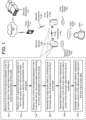
- FIG. 1 illustrates a system for beamforming including a first device 110a (e.g., a primary earbud) and a second device 110b (e.g., a secondary earbud).
- the first device 110a and the second device 110b may communicate using a first wireless connection 114a, which may be a Bluetooth, NFMI, or similar connection.
- the first device 110a and second device 110b communicate using a wired connection.
- the first device 110a communicates with a third device 112, such as a smartphone, smart watch, or similar device, using a second connection 114b, which may also be a wireless connection such as a Bluetooth Wi-Fi connection or a wired connection.
- a first wireless connection 114a between the first device 110a and the second device 110b is a low-power connection such as BLE; the second wireless connection 114b may include a high-bandwidth connection such as EDR in addition to or instead of a BLE connection.
- the third device 112 may communicate with one or more remote device(s) 120, which may be server devices, via a network 199, which may be the Internet, a wide- or local-area network, or any other network.
- the first device 110a may output first output audio 15a
- the second device 110b may output second output audio 15b.
- the first device 110a and second device 110b may capture input audio 11 from a user 5, process the input audio 11, and/or send the input audio 11 and/or processed input audio to the third device 112 and/or remote device(s) 120, as described in greater detail below.
- the device 110a/110b generates (136) first output audio data by combining the first audio data with at least a portion of the third audio data.
- the device 110a/110b generates (138) reference audio data by subtracting at least a portion of the first audio data and at least a portion of the third audio data from the second audio data.
- the device 110a/110b generates (140) generates second output audio data by subtracting at least a portion of the reference audio data from the first output audio data.
- the device 110a/110b may send the second output audio data to another device for output and/or for analysis, such as automatic speech recognition.
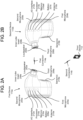
- FIGS. 2A and 2B illustrate an embodiment of the first device 110a and second device 110b, respectively.
- the first device 110a and second device 110b have similar features; in other embodiments, as noted above, the second device 110b (i.e., the secondary device) may have only a subset of the features of the first device 110a.
- the first device 110a and second device 110b are depicted as wireless earbuds having an inner-lobe insert; as mentioned above, however, the present disclosure is not limited to only wireless earbuds, and any wearable audio input/output system, such as a headset, over-the-ear headphones, or other such systems, is within the scope of the present disclosure.
- the devices 110a/110b may include a loudspeaker 202a/202b, one or more external microphone(s) (such as first microphones 204a/204b and second microphones 205a/205b) and one or more internal microphones (such as third microphones 206a/206b).
- the loudspeaker 202a/202b may be any type of loudspeaker, such as an electrodynamic speaker, electrostatic speaker, diaphragm speaker, or piezoelectric loudspeaker; the microphones 204a/204b/205a/205b/206a/206b may be any type of microphones, such as piezoelectric or MEMS microphones.
- Each device 110a/110b may include one or more microphones 204a/204b/205a/205b/206a/206b.
- the loudspeaker 202a/202b and microphones 204a/204b/205a/205b/206a/206b may be mounted on, disposed on, or otherwise connected to the device 110a/110b.
- the devices 110a/110b further include an inner-lobe insert 208a/208b that may bring the loudspeaker 202a/202b and/or third microphone(s) 206a/206b closer to the eardrum of the user and/or block some ambient noise.
- One or more batteries 207a/207b may be used to supply power to the devices 110a/110b.
- One or more antennas 210a/210b may be used to transmit and/or receive wireless signals over the first connection 114a and/or second connection 114b; an I/O interface 212a/212b contains software and hardware to control the antennas 210a/210b and transmit signals to and from other components.
- a processor 214a/214b may be used to execute instructions in a memory 216a/216b; the memory 216a/216b may include volatile memory (e.g., random-access memory) and/or non-volatile memory or storage (e.g., flash memory).
- One or more sensors 218a/218b such as accelerometers, gyroscopes, or any other such sensor may be used to sense physical properties related to the devices 110a/110b, such as orientation; this orientation may be used to determine whether either or both of the devices 110a/110b are currently disposed in an ear of the user (i.e., the "in-ear" status of each device).
- the instructions may correspond to the audio-processing component 226, voice-activity detection component 228, wakeword detection component 229, and/or other components discussed above.
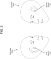
- FIG. 3 illustrates a right view 302a and a left view 302b of a user of the first device 110a and the second device 110b.
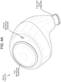
- FIG. 4B illustrates another one embodiment of the placement of the first microphone 204a/204b and the second microphone 205a/205b.
- FIG. 4C illustrates one embodiment of the placement of the loudspeaker 202a/202b, third microphone 206a/206b, inner-lobe insert 208a/208b, and sensor(s) 218a/218b.
- the present disclosure is not limited, however, to only these placements, and other placements of the microphones are within its scope.
- FIG. 5 illustrates a system for beamforming an audio signal received from first, second, and third microphones according to embodiments of the present disclosure.
- the first microphone 204a/204b is used as the sole primary microphone
- the second microphone 205a/205b and the third microphone 206a/206b are used as secondary microphones.
- a first filter 502 which may be a finite-impulse-response (FIR) filter, infinite-impulse-response (IIR) filter, other filter, or other signal-processing element, receives audio data from the first microphone 204a/204b and modifies it in accordance with a first steering coefficient ⁇ 1 .
- FIR finite-impulse-response
- IIR infinite-impulse-response
- a first summing component 506 subtracts the output of the first filter 502 from audio data received from the third microphone 206a/206b, and a second summing component 508 subtracts the output of the second filter 504 from audio data received from the second microphone 205a/205b.
- the summing components 506, 508 may be hardware or software adder components; in some embodiments, the summing components 506, 508 are part of the filters 502/504.
- a third filter 510 and a fourth filter 512 may then use the outputs of the summing components 506 and 508 to cancel and/or suppress residual echoes.
- a third coefficient ⁇ 1 may be associated with the third filter 510 and a fourth coefficient ⁇ 1 may be associated with the fourth filter 512, which may implement the coefficients using a corresponding set of filter coefficients.
- the third coefficient ⁇ 1 and the fourth coefficient ⁇ 2 may be selected to maximize a signal-to-noise ratio of output audio data 516.
- the device 110a/110b may determine the third coefficient ⁇ 1 and the fourth coefficient ⁇ 2 using any technique known in the art, such as gradient descent or least-mean-squares.
- a fifth summing component 514 may then subtract the output of the third filter 510 and the fourth filter 512 from the audio data from the first microphone 204a/204b to create the output audio data 516.
- the device 110a/110b also receives a far-end reference signal 518.
- This far-end reference signal 518 may correspond to audio data received by the device 110a/110b for playback thereon, such as voice data representing speech during (e.g.) a phone call, music data corresponding to music, or other data.
- a fifth filter 520 may modify the far-end reference signal 518 by, for example, changing its phase and/or magnitude, and the fifth summing element 514 may subtract the result from the output audio data 516.
- FIG. 6 illustrates another system for beamforming an audio signal received from first, second, and third microphones according to embodiments of the present disclosure.
- the first microphone 204a/204b is used as the first primary microphone
- the third microphone 206a/206b is used as the second primary microphone
- the second microphone 205a/205b is used as a secondary microphone.
- the primary microphones may be used to generate target audio (i.e., desired audio from a selected direction) and the secondary microphone may be used to generate reference or noise audio, which may be removed from the target audio as described below.
- a first summing component 602 adds the output of the first microphone 204a/204b with the output of the third microphone 206a/206b, as modified by a first filter 604 having a first steering coefficient ⁇ 0 .
- the summing component 602 may be a hardware or software adder component; in some embodiments, the summing component 602 is part of the first filter 604.
- the first filter 604 may be an FIR or other filter and may include a set of filter coefficients that correspond to the first steering coefficient ⁇ 1 , and the first filter 604 may modify the phase and/or magnitude of the audio data.
- the first steering coefficient ⁇ 1 may correspond to the relative placement, properties, and orientation of the microphones 204/205/206 and may vary in accordance with a desired steering angle (e.g., the first steering coefficient ⁇ 1 may have different values for 0°, 45°, and 90° steering angles).
- the first steering coefficient ⁇ 1 may be determined by simulation and/or experimentation.
- a second summing element 606 removes audio data received by the first microphone 204a/204b - as modified by a second filter 608 having a second steering coefficient ⁇ 1 - and audio data received by the third microphone 206a/206b - as modified by a third filter 610 having a third steering coefficient ⁇ 2 - from audio data from the second microphone 205a/205b.
- the output of the second summing element 606 may be referred to as a reference signal or as a noise signal.
- the device 110a/110b also receives a far-end reference signal 618.
- This far-end reference signal 618 may correspond to audio data received by the device 110a/110b for playback thereon, such as voice data representing speech during (e.g.) a phone call, music data corresponding to music, or other data.
- a fifth filter 620 may modify the far-end reference signal 618 by, for example, changing its phase and/or magnitude, and the fifth summing element 614 may subtract the result from the output audio data 616.
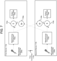
- FIG. 7 illustrates a system for beamforming an audio signal received from first, second, and third microphones from each of two devices according to embodiments of the present disclosure.
- the first device 110a includes a first beamforming component 802a, which may include the system of FIG. 6 as explained in greater detail below.
- the second device 110b includes a second beamforming component 802b.
- the first beamforming component 802a sends, via the first connection 114a, output audio data to the second device 110b;
- the second beamforming component 802b sends, via the first connection 114a, output audio data to the first device 110a.
- the first device 110a receives the output audio data from the second device 110b, and a first summing component 704a combines the output of the beamforming component 802a with the audio data received from the second device 110b to create output audio data 706a.
- the second device 110a receives the output audio data from the first device 110a, and a second summing component 704b combines the output of the beamforming component 802b with the audio data received from the first device 110a to create output audio data 706b.
- the output of each beamforming component 702a, 702b may be filtered to change its phase, amplitude, or other property prior to being added with the other output of the other beamforming component 702a, 702b using filters 708a, 708b.
- the first device 110a and second device 110b may similarly share one or more filter coefficients using the first connection 114a.
- the second device 110b sends one or more filter coefficients, such as the filter coefficients corresponding to the ⁇ 1 or ⁇ 1 coefficients described above, to the first device 110a.
- the first device 110a may then aggregate corresponding coefficients by, for example, finding an average value between corresponding coefficients.
- the first device 110a may thereafter update its filters with the aggregated coefficients and/or send the aggregated coefficients to the second device 110b, which may similarly update its filters.
- the first device 110a sends data received by one or more microphones 204a, 205a, 206a to the second device 110b; the second device 110b may similarly send data received by one or more microphones 204b, 205b, 206b to the first device 110a.
- the first device 110a may thus, for example, use four microphones as primary microphones: the first microphone 204a and third microphone 205a of the first device 110a and the first microphone 204b and third microphone 205b of the second device 110b.
- the first device 110a may use the second microphone 205a and the second microphone 205b as secondary microphones.
- either the second microphone 206a or the first microphone 205b is designated as a secondary microphone.
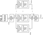
- FIG. 8 illustrates components of the system in greater detail.
- An analysis filterbank 802 receives the first audio signal 814a from the first microphone array 102a and the second audio signal 814b from the second microphone array 102b. Each audio signal 814a/814b may correspond to one or more microphones.
- the analysis filterbank 802 may include hardware, software, and/or firmware for processing audio signals and may convert the first and/or second audio data 814a/814b from the time domain into the frequency / sub-band domain.
- the analysis filterbank 802 may thus create one or more frequency-domain signals 816; the frequency-domain signals 816 may correspond to multiple adjacent frequency bands.
- the analysis filterbank 110 may include, for example, a uniform discrete Fourier transform (DFT) filterbank that converts the time-domain input audio data 102a/102b into one or more frequency-domain signals 816.
- the frequency-domain signal 816 may incorporate audio signals corresponding to multiple different microphones as well as different sub-bands (i.e., frequency ranges) as well as different frame indices (i.e., time ranges).
- the frequency-domain signal(s) 816 created by the analysis filterbank 802 is/are received by one or more beamforming components 804a, 804b, ... 804n, collectively referred to herein as beamforming components 804.
- the number of beamforming components 804 corresponds to the number of frequency sub-bands of the frequency-domain signal 816; if, for example, the analysis filterbank 802 breaks the audio signals 102a/102b into ten different frequency sub-bands, the system includes ten beamforming components 804 to process each of the ten different frequency sub-bands.
- Each beamforming component 804 may include the filters and summing components described above with reference to FIGS. 6 and 7 .
- a sound (such as an utterance) may be received by more than one microphone, such as by the first microphone 204a/204b, the second microphone 205a/205b, and the third microphone 206a/206b. Because the microphones are disposed at different locations, each microphone may capture a different version of the sound; each version may differ in one or more properties or attributes, such as volume, time delay, frequency spectrum, power level, amount and type of background noise, or any other similar factor. Each beamforming component 804 may utilize these differences to isolate and boost sound from a particular azimuth direction and/or elevation while suppressing sounds from other azimuth directions and/or elevation. Any particular system and method for beamforming is within the scope of the present invention.
- the beamforming component is a minimum-variance distortionless-response (MVDR) beamformer.
- MVDR minimum-variance distortionless-response
- Q is the covariance matrix and may correspond to the cross-power spectral density (CPSD) of a noise field surrounding the system 100
- d is a steering vector that corresponds to a transfer function between the system 100 and a target source of sound located at a distance (e.g., two meters) from the system 100.
- the covariance matrix may define the spatial relationships between the microphones; this covariance matrix may include a number of covariance values corresponding to each pair of microphones.
- the covariance matrix is a matrix whose covariance value in the i, j position represents the covariance between the i th and j th elements of the microphone arrays.
- the covariance matrix is a spatial covariance matrix (SCM).
- a covariance value corresponding to the second row and third column of the matrix corresponds to the relationship between second and third microphones.
- the values of the diagonal of the covariance matrix differ for the first and second microphone arrays; the covariance values of the diagonal corresponding to the first microphone may, for example, be greater than the covariance values of the diagonal corresponding to the second microphone.
- a different covariance matrix is determined for each of multiple frequency sub-bands. For example, a first covariance matrix is determined for frequencies between 20 Hz and 5 kHz; a second covariance matrix is determined for frequencies between 5 kHz and 10 kHz; a third covariance matrix is determined for frequencies between 10 kHz and 15 kHz; and a fourth covariance matrix is determined for frequencies between 15 kHz and 20 kHz. Any number of covariance matrices for any number or breakdown of frequency sub-bands is, however, within the scope of the present disclosure.
- Each beamforming component 804 may create a beamformed frequency-domain signal 818 that, as described above, emphasizes or boosts audio from a particular azimuth direction and/or elevation for, in some embodiments, the frequency sub-band associated with each beamforming component 804.
- the beamformed frequency-domain signal(s) 818 may be combined, if necessary, using a summation component 808.
- synthesis filterbank 810 converts the combined signal into time-domain audio output data 812 which may be sent to a downstream component (such as a speech processing system) for further operations (such as determining speech processing results using the audio output data).
- the synthesis filterbank 810 may include an inverse FFT function for synthesizing the time-domain audio output data; any system or method for creating time-domain signals from frequency-domain signals is, however, within the scope of the present disclosure.
- Boost short for "Adaptive Boosting" combined with decision trees, and random forests.
- CRFs are a type of discriminative undirected probabilistic graphical models and may predict a class label for a sample while taking into account contextual information for the sample.
- CRFs may be used to encode known relationships between observations and construct consistent interpretations.
- a CRF model may thus be used to label or parse certain sequential data, like query text as described above.
- Classifiers may issue a "score" indicating which category the data most closely matches. The score may provide an indication of how closely the data matches the category.
- Training a machine learning component such as, in this case, one of the first or second models, requires establishing a "ground truth" for the training examples.
- the term "ground truth” refers to the accuracy of a training set's classification for supervised learning techniques.
- known types for previous queries may be used as ground truth data for the training set used to train the various components / models.
- Various techniques may be used to train the models including backpropagation, statistical learning, supervised learning, semi-supervised learning, stochastic learning, stochastic gradient descent, or other known techniques.
- many different training examples may be used to train the classifier(s) / model(s) discussed herein.
- new classifiers / models may be trained to update the classifiers / models as desired.
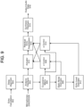
- FIG. 9 is another diagram of a beamforming system in accordance with embodiments of the present disclosure.
- the analysis filterbank 802 receives audio data from the microphones 204/205/205 and, as described above, creates one or more frequency bins corresponding to different frequencies of the audio data.
- Echo-cancellation data 902 may be received from for example, the far-end reference signal 618, and the delay of the echo-cancellation data 902 may be changed with a delay-alignment unit 904; this delay-adjusted echo-cancellation data may be used by the analysis filterbank 802 to create the frequency data.
- the beamforming component may include the covariance matrix described above.
- the beamforming unit may further include a static noise estimator 906 for estimating static noise in the audio data, such as constant noise.
- the beamforming unit 802 may further include a ⁇ control unit 908 for determining the ⁇ coefficients described above; each ⁇ control unit 908 may determine different ⁇ coefficients for each frequency bin, and the ⁇ coefficients may vary based on the look angle or steering angle.
- the beamforming unit 802 may further include an actuator 910 that includes the filters and summing components described above with reference to FIGS. 6 and 7 .
- a residual echo level may be estimated by an echo level estimator 912; the residual echo level may be used by an ⁇ control unit 914 to determine the ⁇ coefficients, as described above.
- a residual echo suppression unit 916 may use the ⁇ coefficients to suppress a residual echo, as described above.
- a synthesis filterbank 810 may combine the frequency-domain outputs corresponding to the one or more frequency bins and create time-domain audio output data 918.
- FIG. 10 is a block diagram conceptually illustrating example components of the system 100.
- the system 100 may include computer-readable and computer-executable instructions that reside on the system, as will be discussed further below.
- the system 100 may include one or more audio capture device(s), such as a first microphone array 102a and a second microphone array 102b, each of which may include a plurality of microphones.
- the audio capture device(s) may be integrated into a single device or may be separate.
- the system 100 may also include an audio output device for producing sound, such as speaker(s) 1010.
- the audio output device may be integrated into a single device or may be separate.
- the system 100 may include an address/data bus 1012 for conveying data among components of the system 100. Each component within the system may also be directly connected to other components in addition to (or instead of) being connected to other components across the bus 1012.
- the system 100 may include one or more controllers/processors 1004 that may each include a central processing unit (CPU) for processing data and computer-readable instructions, and a memory 1006 for storing data and instructions.
- the memory 1006 may include volatile random access memory (RAM), non-volatile read only memory (ROM), non-volatile magnetoresistive (MRAM) and/or other types of memory.
- the system 100 may also include a data storage component 1008, for storing data and controller/processor-executable instructions (e.g., instructions to perform operations discussed herein).
- the data storage component 1008 may include one or more non-volatile storage types such as magnetic storage, optical storage, solid-state storage, etc.
- the system 100 may also be connected to removable or external non-volatile memory and/or storage (such as a removable memory card, memory key drive, networked storage, etc.) through the input/output device interfaces 1002.
- Computer instructions for operating the system 100 and its various components may be executed by the controller(s)/processor(s) 1004, using the memory 1006 as temporary "working" storage at runtime.
- the computer instructions may be stored in a non-transitory manner in non-volatile memory 1006, storage 1008, and/or an external device.
- some or all of the executable instructions may be embedded in hardware or firmware in addition to or instead of software.
- the system may include input/output device interfaces 1002.
- input/output device interfaces 1002 A variety of components may be connected through the input/output device interfaces 1002, such as the speaker(s) 1010, the microphone arrays 102a/102b, and a media source such as a digital media player (not illustrated).
- the input/output interfaces 1002 may include A/D converters (not shown) and/or D/A converters (not shown).
- the system may include one or more beamforming components 802 - which may each include one or more covariance matrix(es) 806 - analysis filterbank 802, synthesis filterbank 810, and/or other components for performing the processes discussed above.
- the input/output device interfaces 1002 may also include an interface for an external peripheral device connection such as universal serial bus (USB), FireWire, Thunderbolt or other connection protocol.
- the input/output device interfaces 1002 may also include a connection to one or more networks 1099 via an Ethernet port, a wireless local area network (WLAN) (such as WiFi) radio, Bluetooth, and/or wireless network radio, such as a radio capable of communication with a wireless communication network such as a Long Term Evolution (LTE) network, WiMAX network, 3G network, etc.
- WLAN wireless local area network
- LTE Long Term Evolution
- 3G 3G network
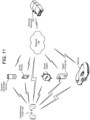
- multiple devices may contain components of the system 100 and the devices may be connected over a network 199.
- the network 199 may include one or more local-area or private networks and/or a wide-area network, such as the internet.
- Local devices may be connected to the network 199 through either wired or wireless connections.
- a speech-controlled device, a tablet computer, a smart phone, a smart watch, and/or a vehicle may be connected to the network 199.
- One or more remote device(s) 120 may be connected to the network 199 and may communicate with the other devices therethrough.
- the devices 110a/110b may similarly be connected to the remote device(s) 120 either directly or via a network connection to one or more of the local devices.
- the devices 110a/110b may capture audio using one or more microphones or other such audio-capture devices; the headphones 110a/110b may perform audio processing, voice-activity detection, and/or wakeword detection, and the remove device(s) 120 may perform automatic speech recognition, natural-language processing, or other functions.
- each of the devices may include different components for performing different aspects of the processes discussed above.
- the multiple devices may include overlapping components.
- the components listed in any of the figures herein are exemplary, and may be included a stand-alone device or may be included, in whole or in part, as a component of a larger device or system.
- certain components, such as the beamforming components 802 may be arranged as illustrated or may be arranged in a different manner, or removed entirely and/or joined with other non-illustrated components.
- the concepts disclosed herein may be applied within a number of different devices and computer systems, including, for example, general-purpose computing systems, multimedia set-top boxes, televisions, stereos, radios, server-client computing systems, telephone computing systems, laptop computers, cellular phones, personal digital assistants (PDAs), tablet computers, wearable computing devices (watches, glasses, etc.), other mobile devices, etc.
- general-purpose computing systems multimedia set-top boxes, televisions, stereos, radios
- server-client computing systems telephone computing systems
- laptop computers cellular phones
- PDAs personal digital assistants
- tablet computers wearable computing devices (watches, glasses, etc.), other mobile devices, etc.
- aspects of the disclosed system may be implemented as a computer method or as an article of manufacture such as a memory device or non-transitory computer readable storage medium.
- the computer readable storage medium may be readable by a computer and may comprise instructions for causing a computer or other device to perform processes described in the present disclosure.
- the computer readable storage medium may be implemented by a volatile computer memory, non-volatile computer memory, hard drive, solid-state memory, flash drive, removable disk and/or other media.
- components of system may be implemented in firmware and/or hardware, such as an acoustic front end (AFE), which comprises, among other things, analog and/or digital filters (e.g., filters configured as firmware to a digital signal processor (DSP)).
- AFE acoustic front end
- DSP digital signal processor
- Some or all of the beamforming component 802 may, for example, be implemented by a digital signal processor (DSP).
- Disjunctive language such as the phrase "at least one of X, Y, Z," unless specifically stated otherwise, is understood with the context as used in general to present that an item, term, etc., may be either X, Y, or Z, or any combination thereof (e.g., X, Y, and/or Z). Thus, such disjunctive language is not generally intended to, and should not, imply that certain embodiments require at least one of X, at least one of Y, or at least one of Z to each be present.
- the term “a” or “one” may include one or more items unless specifically stated otherwise.
- the phrase “based on” is intended to mean “based at least in part on” unless specifically stated otherwise.
Landscapes
- Engineering & Computer Science (AREA)
- Physics & Mathematics (AREA)
- Acoustics & Sound (AREA)
- Signal Processing (AREA)
- Health & Medical Sciences (AREA)
- Otolaryngology (AREA)
- Audiology, Speech & Language Pathology (AREA)
- Human Computer Interaction (AREA)
- Multimedia (AREA)
- General Health & Medical Sciences (AREA)
- Theoretical Computer Science (AREA)
- Quality & Reliability (AREA)
- Computational Linguistics (AREA)
- General Engineering & Computer Science (AREA)
- General Physics & Mathematics (AREA)
- Circuit For Audible Band Transducer (AREA)
- Obtaining Desirable Characteristics In Audible-Bandwidth Transducers (AREA)
Claims (15)
- Computerimplementiertes Verfahren, das Folgendes umfasst:Empfangen (130), von einem ersten Mikrofon (204a, 204b), das auf einer In-Ear-Audiovorrichtung (110a, 110b) angeordnet ist, erster Audiodaten, die einer ersten Repräsentation eines ersten Audios entsprechen;Empfangen (132), von einem zweiten Mikrofon (205a, 205b), das auf der In-Ear-Audiovorrichtung (110a, 110b) angeordnet ist, zweiter Audiodaten, die einer zweiten Repräsentation des ersten Audios entsprechen;Empfangen, von einem dritten Mikrofon (206a, 206b), das auf einem Innenläppcheneinsatz (208a, 208b) der In-Ear-Audiovorrichtung (110a, 110b) angeordnet ist, dritter Audiodaten, die einer dritten Repräsentation des ersten Audios entsprechen;Erzeugen (136) erster Ausgabeaudiodaten durch Kombinieren der ersten Audiodaten mit mindestens einem Teil der dritten Audiodaten;Erzeugen (138) von Referenzaudiodaten durch Subtrahieren mindestens eines Teils der ersten Audiodaten und mindestens eines Teils der dritten Audiodaten von den zweiten Audiodaten; undErzeugen (140) zweiter Ausgabeaudiodaten durch Subtrahieren mindestens eines Teils der Referenzaudiodaten von den ersten Ausgabeaudiodaten.
- Computerimplementiertes Verfahren nach Anspruch 1, wobei das Erzeugen der ersten Ausgabeaudiodaten ferner Folgendes umfasst:Erzeugen, unter Verwendung eines Satzes von Filterkoeffizienten, modifizierter zweiter Audiodaten durch Ändern einer Phase der zweiten Audiodaten; undHinzufügen der ersten Audiodaten und der modifizierten zweiten Audiodaten.
- Computerimplementiertes Verfahren nach Anspruch 1 oder 2, wobei das Erzeugen der Referenzaudiodaten ferner Folgendes umfasst:Erzeugen modifizierter erster Audiodaten durch Ändern einer Phase der ersten Audiodaten gemäß einer ersten Übertragungsfunktion, die eine Beziehung zwischen dem ersten Mikrofon (204a, 204b) und dem zweiten Mikrofon (205a, 205b) definiert;Erzeugen modifizierter zweiter Audiodaten durch Ändern einer Phase der zweiten Audiodaten gemäß einer zweiten Übertragungsfunktion, die eine Beziehung zwischen dem zweiten Mikrofon (205a, 205b) und dem dritten Mikrofon definiert; undSubtrahieren der modifizierten ersten Audiodaten und der modifizierten zweiten Audiodaten von den dritten Audiodaten.
- Computerimplementiertes Verfahren nach Anspruch 1, 2 oder 3, das ferner Folgendes umfasst:Bestimmen, dass eine Verstärkung, die den zweiten Ausgabeaudiodaten entspricht, größer oder gleich 1 ist;Bestimmen eines Verstärkungskoeffizienten, der der Verstärkung entspricht; undErzeugen dritter Ausgabeaudiodaten durch Modifizieren der zweiten Ausgabeaudiodaten, unter Verwendung des Verstärkungskoeffizienten.
- Computerimplementiertes Verfahren nach Anspruch 1, 2, 3 oder 4, das ferner Folgendes umfasst:Empfangen, von einer zweiten In-Ear-Audiovorrichtung (110b), von dritten Ausgabeaudiodaten;Erzeugen, unter Verwendung eines Satzes von Filterkoeffizienten, modifizierter dritter Ausgabeaudiodaten durch Ändern einer Phase der dritten Ausgabeaudiodaten; undErzeugen vierter Ausgabeaudiodaten durch Hinzufügen der zweiten Ausgabeaudiodaten und der modifizierten dritten Ausgabeaudiodaten.
- Computerimplementiertes Verfahren nach Anspruch 1, 2, 3, 4 oder 5, das ferner Folgendes umfasst:Bestimmen, basierend auf einem Signal-Rausch-Verhältnis der zweiten Ausgabeaudiodaten, eines ersten Filterkoeffizienten;Empfangen, von einer zweiten In-Ear-Audiovorrichtung (110b), eines zweiten Filterkoeffizienten;Bestimmen eines dritten Filterkoeffizienten zumindest teilweise basierend auf dem Mitteln des ersten Filterkoeffizienten und des zweiten Filterkoeffizienten; undSenden, an die zweite In-Ear-Audiovorrichtung (110b), des dritten Filterkoeffizienten.
- Computerimplementiertes Verfahren nach Anspruch 1, 2, 3, 4, 5 oder 6, das ferner Folgendes umfasst:Bestimmen, basierend auf einem Signal-Rausch-Verhältnis der zweiten Ausgabeaudiodaten, eines ersten Satzes von Filterkoeffizienten;Bestimmen einer Verringerung des Signal-Rausch-Verhältnisses von einem ersten Wert zu einem zweiten Wert;Bestimmen eines Gradienten, der einer Differenz zwischen dem ersten Wert und dem zweiten Wert entspricht; undBestimmen eines zweiten Satzes von Filterkoeffizienten basierend auf dem Gradienten und dem ersten Satz von Filterkoeffizienten.
- System, das Folgendes umfasst:eine In-Ear-Audiovorrichtung (110a, 110b);ein erstes Mikrofon (204a, 204b), das auf der In-Ear-Audiovorrichtung (110a, 110b) angeordnet ist;ein zweites Mikrofon (205a, 205b), das auf der In-Ohr-Audiovorrichtung (110a, 110b) angeordnet ist;ein drittes Mikrofon (206a, 206b), das auf einem Innenläppcheneinsatz (208a, 208b) der In-Ear-Audiovorrichtung (110a, 110b) angeordnet ist;mindestens einen Prozessor (214a, 214b); undmindestens einen Speicher (216a, 216b), der Anweisungen beinhaltet, die, wenn sie durch den mindestens einen Prozessor (214a, 214b) ausgeführt werden, die In-Ear-Audiovorrichtung (110a, 110b) veranlassen, um:von dem ersten Mikrofon (204a, 204b), erste Audiodaten, zu empfangen (130), die einer ersten Repräsentation des ersten Audios entsprechen;von dem zweiten Mikrofon (205a, 205b), zweite Audiodaten zu empfangen (132), die einer zweiten Repräsentation des ersten Audios entsprechen;von dem dritten Mikrofon, dritte Audiodaten zu empfangen, die einer dritten Repräsentation des ersten Audios entsprechen;erste Ausgabeaudiodaten durch Kombinieren der ersten Audiodaten mit mindestens einem Teil der dritten Audiodaten zu erzeugen (136);Referenzaudiodaten durch Subtrahieren mindestens eines Teils der ersten Audiodaten und mindestens eines Teils der dritten Audiodaten von den zweiten Audiodaten zu erzeugen (138); undzweite Ausgabeaudiodaten durch Subtrahieren mindestens eines Teils der Referenzaudiodaten von den ersten Ausgabeaudiodaten zu erzeugen (140).
- System nach Anspruch 8, wobei der mindestens eine Speicher (216a, 216b) ferner Anweisungen beinhaltet, die, wenn Sie durch den mindestens einen Prozessor (214a, 214b) ausgeführt werden, die In-Ear-Audiovorrichtung (110a, 110b) ferner veranlassen, um:unter Verwendung eines Satzes von Filterkoeffizienten modifizierte zweite Audiodaten durch Ändern einer Phase der zweiten Audiodaten zu erzeugen; unddie ersten Audiodaten und die modifizierten zweiten Audiodaten hinzuzufügen.
- System nach Anspruch 8 oder 9, wobei der mindestens eine Speicher (216a, 216b) ferner Anweisungen beinhaltet, die, wenn sie durch den mindestens einen Prozessor (214a, 214b) ausgeführt werden, die In-Ear-Audiovorrichtung (110a, 110b) veranlassen, um:modifizierte erste Audiodaten durch Ändern einer ersten Phase der ersten Audiodaten gemäß einer ersten Übertragungsfunktion zu erzeugen, die eine Beziehung zwischen dem ersten Mikrofon (204a, 204b) und dem zweiten Mikrofon (205a, 205b) definiert;unter Verwendung eines zweiten Satzes von Filterkoeffizienten modifizierte zweite Audiodaten durch Ändern einer zweiten Phase der zweiten Audiodaten gemäß einer zweiten Übertragungsfunktion zu erzeugen, die eine Beziehung zwischen dem zweiten Mikrofon (205a, 205b) unddem dritten Mikrofon definiert; unddie modifizierten ersten Audiodaten und die modifizierten zweiten Audiodaten von den dritten Audiodaten zu subtrahieren.
- System nach Anspruch 8, 9 oder 10, wobei der mindestens eine Speicher (216a, 216b) ferner Anweisungen beinhaltet, die, wenn sie durch den mindestens einen Prozessor (214a, 214b) ausgeführt werden, die In-Ear-Audiovorrichtung (110a, 110b) ferner veranlassen, um:zu bestimmen, dass eine Verstärkung, die den zweiten Ausgabeaudiodaten entspricht, größer oder gleich 1 ist;einen Verstärkungskoeffizienten zu bestimmen, der der Verstärkung entspricht; unddritte Ausgabeaudiodaten durch Modifizieren die zweiten Ausgabeaudiodaten unter Verwendung des Verstärkungskoeffizienten zu erzeugen.
- System nach Anspruch 8, 9, 10 oder 11, wobei der mindestens eine Speicher (216a, 216b) ferner Anweisungen beinhaltet, die, wenn sie durch den mindestens einen Prozessor (214a, 214b) ausgeführt werden, die In-Ear-Audiovorrichtung (110a, 110b) ferner veranlassen, um:von einer zweiten In-Ear-Audiovorrichtung (110b), dritte Ausgabeaudiodaten zu empfangen;unter Verwendung eines Satzes von Filterkoeffizienten modifizierte dritte Ausgabeaudiodaten durch Ändern einer Phase der dritten Ausgabeaudiodaten zu erzeugen; undvierte Ausgabeaudiodaten durch Hinzufügen der zweiten Ausgabeaudiodaten und der modifizierten dritten Ausgabeaudiodaten zu erzeugen.
- System nach Anspruch 8, 9, 10, 11 oder 12, wobei der mindestens eine Speicher (216a, 216b) ferner Anweisungen beinhaltet, die, wenn sie durch den mindestens einen Prozessor (214a, 214b) ausgeführt werden, die In-Ear-Audiovorrichtung (110a, 110b) ferner veranlassen, um:basierend auf einem Signal-Rausch-Verhältnis der zweiten Ausgabeaudiodaten, einen ersten Filterkoeffizienten zu bestimmen;von einer zweiten In-Ear-Audiovorrichtung (110b) einen zweiten Filterkoeffizienten zu empfangen;einen dritten Filterkoeffizienten zumindest teilweise basierend auf dem Mitteln des ersten Filterkoeffizienten und des zweiten Filterkoeffizienten zu bestimmen; undan die zweite In-Ear-Audiovorrichtung (110b) die dritten Filterkoeffizienten zu senden.
- System nach Anspruch 8, 9, 10, 11, 12 oder 13, wobei der mindestens eine Speicher (216a, 216b) ferner Anweisungen beinhaltet, die, wenn sie durch den mindestens einen Prozessor (214a, 214b) ausgeführt werden, die In-Ear-Audiovorrichtung (110a, 110b) ferner veranlassen, um:basierend auf einem Signal-Rausch-Verhältnis der zweiten Ausgabeaudiodaten einen ersten Satz von Filterkoeffizienten zu bestimmen;eine Verringerung des Signal-Rausch-Verhältnisses von einem ersten Wert zu einem zweiten Wert zu bestimmen;einen Gradienten zu bestimmen, der einer Differenz zwischen dem ersten Wert und dem zweiten Wert entspricht; undeinen zweiten Satz von Filterkoeffizienten basierend auf dem Gradienten und dem ersten Satz von Filterkoeffizienten zu bestimmen.
- System nach Anspruch 8, 9, 10, 11, 12, 13 oder 14, wobei der mindestens eine Speicher (216a, 216b) ferner Anweisungen beinhaltet, die, wenn sie durch den mindestens einen Prozessor (214a, 214b) ausgeführt werden, die In-Ear-Audiovorrichtung (110a, 110b) ferner veranlassen, um:von einer Benutzervorrichtung Referenzaudiodaten zu empfangen, die Referenzaudios entsprechen;unter Verwendung eines Satzes von Filterkoeffizienten, modifizierte Referenzaudiodaten durch Ändern einer Phase der Referenzaudiodaten zu erzeugen;dritte Ausgabeaudiodaten durch Subtrahieren mindestens eines Teils der modifizierten Referenzaudiodaten von den ersten Ausgabeaudiodaten zu erzeugen.
Applications Claiming Priority (2)
| Application Number | Priority Date | Filing Date | Title |
|---|---|---|---|
| US16/142,992 US10516934B1 (en) | 2018-09-26 | 2018-09-26 | Beamforming using an in-ear audio device |
| PCT/US2019/046749 WO2020068294A1 (en) | 2018-09-26 | 2019-08-16 | Beamforming using an in-ear audio device |
Publications (3)
| Publication Number | Publication Date |
|---|---|
| EP3857912A1 EP3857912A1 (de) | 2021-08-04 |
| EP3857912B1 true EP3857912B1 (de) | 2025-04-30 |
| EP3857912B8 EP3857912B8 (de) | 2025-06-11 |
Family
ID=67809694
Family Applications (1)
| Application Number | Title | Priority Date | Filing Date |
|---|---|---|---|
| EP19762032.1A Active EP3857912B8 (de) | 2018-09-26 | 2019-08-16 | Strahlformung unter verwendung eines im-ohr-hörgerätes |
Country Status (3)
| Country | Link |
|---|---|
| US (2) | US10516934B1 (de) |
| EP (1) | EP3857912B8 (de) |
| WO (1) | WO2020068294A1 (de) |
Families Citing this family (16)
| Publication number | Priority date | Publication date | Assignee | Title |
|---|---|---|---|---|
| US10516934B1 (en) * | 2018-09-26 | 2019-12-24 | Amazon Technologies, Inc. | Beamforming using an in-ear audio device |
| US11115885B2 (en) * | 2019-04-19 | 2021-09-07 | Qualcomm Incorporated | Audio synchronization during handover |
| CN113038318B (zh) * | 2019-12-25 | 2022-06-07 | 荣耀终端有限公司 | 一种语音信号处理方法及装置 |
| USD945405S1 (en) | 2020-04-01 | 2022-03-08 | Target Brands, Inc. | Earphone |
| WO2021241667A1 (ja) * | 2020-05-29 | 2021-12-02 | 株式会社Jvcケンウッド | 音声入力装置、音声入力システム及び入力音声処理方法 |
| JP7512684B2 (ja) * | 2020-05-29 | 2024-07-09 | 株式会社Jvcケンウッド | 音声入力システム及び入力音声処理方法 |
| US12294828B2 (en) | 2020-09-09 | 2025-05-06 | Audio-Technica Corporation | Wireless earphone |
| US20220101870A1 (en) * | 2020-09-29 | 2022-03-31 | Zinfanite Technologies, Inc. | Noise filtering and voice isolation device and method |
| USD951916S1 (en) * | 2020-11-19 | 2022-05-17 | Shenzhen Ginto E-commerce Co., Limited | Earphone |
| USD973637S1 (en) | 2021-01-12 | 2022-12-27 | Target Brands, Inc. | Earphone |
| USD1013663S1 (en) * | 2021-08-19 | 2024-02-06 | Harman International Industries, Incorporated | Headphone |
| US12418756B2 (en) * | 2022-01-14 | 2025-09-16 | Chromatic Inc. | System and method for enhancing speech of target speaker from audio signal in an ear-worn device using voice signatures |
| US12075215B2 (en) | 2022-01-14 | 2024-08-27 | Chromatic Inc. | Method, apparatus and system for neural network hearing aid |
| US11950056B2 (en) | 2022-01-14 | 2024-04-02 | Chromatic Inc. | Method, apparatus and system for neural network hearing aid |
| US11832061B2 (en) | 2022-01-14 | 2023-11-28 | Chromatic Inc. | Method, apparatus and system for neural network hearing aid |
| US11818547B2 (en) | 2022-01-14 | 2023-11-14 | Chromatic Inc. | Method, apparatus and system for neural network hearing aid |
Citations (4)
| Publication number | Priority date | Publication date | Assignee | Title |
|---|---|---|---|---|
| EP2362677A2 (de) | 2010-02-24 | 2011-08-31 | Yamaha Corporation | Kopfhörermikrophon |
| KR101149981B1 (ko) | 2011-04-19 | 2012-05-31 | 신두식 | 이어마이크로폰 |
| US20140086425A1 (en) | 2012-09-24 | 2014-03-27 | Apple Inc. | Active noise cancellation using multiple reference microphone signals |
| US20180268837A1 (en) | 2017-03-20 | 2018-09-20 | Bose Corporation | Audio signal processing for noise reduction |
Family Cites Families (18)
| Publication number | Priority date | Publication date | Assignee | Title |
|---|---|---|---|---|
| US7039195B1 (en) * | 2000-09-01 | 2006-05-02 | Nacre As | Ear terminal |
| US8452023B2 (en) * | 2007-05-25 | 2013-05-28 | Aliphcom | Wind suppression/replacement component for use with electronic systems |
| FI114358B (fi) | 2002-05-29 | 2004-09-30 | Nokia Corp | Menetelmä digitaalisessa verkkojärjestelmässä päätelaitteen lähetyksen ohjaamiseksi |
| US9099094B2 (en) * | 2003-03-27 | 2015-08-04 | Aliphcom | Microphone array with rear venting |
| US20050058313A1 (en) * | 2003-09-11 | 2005-03-17 | Victorian Thomas A. | External ear canal voice detection |
| US8577062B2 (en) * | 2007-04-27 | 2013-11-05 | Personics Holdings Inc. | Device and method for controlling operation of an earpiece based on voice activity in the presence of audio content |
| JP5549299B2 (ja) * | 2010-03-23 | 2014-07-16 | ヤマハ株式会社 | ヘッドフォン |
| JP6069830B2 (ja) | 2011-12-08 | 2017-02-01 | ソニー株式会社 | 耳孔装着型収音装置、信号処理装置、収音方法 |
| US8798283B2 (en) * | 2012-11-02 | 2014-08-05 | Bose Corporation | Providing ambient naturalness in ANR headphones |
| WO2014075195A1 (en) * | 2012-11-15 | 2014-05-22 | Phonak Ag | Own voice shaping in a hearing instrument |
| WO2014184394A2 (en) | 2014-09-15 | 2014-11-20 | Phonak Ag | Hearing assistance system and method |
| US10616693B2 (en) | 2016-01-22 | 2020-04-07 | Staton Techiya Llc | System and method for efficiency among devices |
| US10080078B2 (en) | 2016-09-16 | 2018-09-18 | Intel Corporation | Battery-less, noise-cancellation headset |
| US10499139B2 (en) | 2017-03-20 | 2019-12-03 | Bose Corporation | Audio signal processing for noise reduction |
| US10575086B2 (en) | 2017-03-22 | 2020-02-25 | Bragi GmbH | System and method for sharing wireless earpieces |
| US10249323B2 (en) * | 2017-05-31 | 2019-04-02 | Bose Corporation | Voice activity detection for communication headset |
| US10229698B1 (en) * | 2017-06-21 | 2019-03-12 | Amazon Technologies, Inc. | Playback reference signal-assisted multi-microphone interference canceler |
| US10516934B1 (en) * | 2018-09-26 | 2019-12-24 | Amazon Technologies, Inc. | Beamforming using an in-ear audio device |
-
2018
- 2018-09-26 US US16/142,992 patent/US10516934B1/en active Active
-
2019
- 2019-08-16 WO PCT/US2019/046749 patent/WO2020068294A1/en not_active Ceased
- 2019-08-16 EP EP19762032.1A patent/EP3857912B8/de active Active
- 2019-11-18 US US16/686,786 patent/US11303991B2/en active Active
Patent Citations (4)
| Publication number | Priority date | Publication date | Assignee | Title |
|---|---|---|---|---|
| EP2362677A2 (de) | 2010-02-24 | 2011-08-31 | Yamaha Corporation | Kopfhörermikrophon |
| KR101149981B1 (ko) | 2011-04-19 | 2012-05-31 | 신두식 | 이어마이크로폰 |
| US20140086425A1 (en) | 2012-09-24 | 2014-03-27 | Apple Inc. | Active noise cancellation using multiple reference microphone signals |
| US20180268837A1 (en) | 2017-03-20 | 2018-09-20 | Bose Corporation | Audio signal processing for noise reduction |
Non-Patent Citations (1)
| Title |
|---|
| NILS WESTERLUND, DAHL MATTIAS, CLAESSON INGVAR: "In-Ear Microphone Techniques for Severe Noise Situations", RESEARCH REPORT NO. 2005:12, BLEKINGE INSTITUTE OF TECHNOLOGY, 1 January 2005 (2005-01-01), XP055330914, Retrieved from the Internet <URL:https://www.diva-portal.org/smash/get/diva2:837857/FULLTEXT01.pdf> |
Also Published As
| Publication number | Publication date |
|---|---|
| US11303991B2 (en) | 2022-04-12 |
| US10516934B1 (en) | 2019-12-24 |
| US20200100018A1 (en) | 2020-03-26 |
| EP3857912A1 (de) | 2021-08-04 |
| EP3857912B8 (de) | 2025-06-11 |
| WO2020068294A1 (en) | 2020-04-02 |
Similar Documents
| Publication | Publication Date | Title |
|---|---|---|
| EP3857912B1 (de) | Strahlformung unter verwendung eines im-ohr-hörgerätes | |
| EP3726856B1 (de) | Hörgerät mit einem schlüsselwortdetektor und einem eigenen sprachdetektor | |
| US10535362B2 (en) | Speech enhancement for an electronic device | |
| WO2022135340A1 (zh) | 一种主动降噪的方法、设备及系统 | |
| CN112767908A (zh) | 基于关键声音识别的主动降噪方法、电子设备及存储介质 | |
| US10154353B2 (en) | Monaural speech intelligibility predictor unit, a hearing aid and a binaural hearing system | |
| CN103392349A (zh) | 用于空间选择性音频增强的系统、方法、设备和计算机可读媒体 | |
| EP4118648B1 (de) | Audioverarbeitung unter verwendung eines verteilten maschinenlernmodells | |
| US11582562B2 (en) | Hearing system comprising a personalized beamformer | |
| US20240422481A1 (en) | A hearing aid configured to select a reference microphone | |
| US12526586B2 (en) | Hearing device comprising an own voice estimator | |
| US12317037B2 (en) | Hearing device comprising a speech intelligibility estimator | |
| EP2916320A1 (de) | Multi-Mikrofonverfahren zur Schätzung von Ziel- und Rauschspektralvarianzen | |
| US12063477B2 (en) | Hearing system comprising a database of acoustic transfer functions | |
| WO2020033245A1 (en) | Audio device using a microphone with pre-adaptation | |
| EP4329335A1 (de) | Verfahren zur reduzierung von windgeräuschen in einem hörgerät | |
| US12300261B1 (en) | Neural sidelobe canceller for target speech separation | |
| US12249311B1 (en) | Multimodal active noise cancellation | |
| EP4597135A1 (de) | Verfahren zur schätzung eines ladezustands für ein hörgerät |
Legal Events
| Date | Code | Title | Description |
|---|---|---|---|
| STAA | Information on the status of an ep patent application or granted ep patent |
Free format text: STATUS: UNKNOWN |
|
| STAA | Information on the status of an ep patent application or granted ep patent |
Free format text: STATUS: THE INTERNATIONAL PUBLICATION HAS BEEN MADE |
|
| PUAI | Public reference made under article 153(3) epc to a published international application that has entered the european phase |
Free format text: ORIGINAL CODE: 0009012 |
|
| STAA | Information on the status of an ep patent application or granted ep patent |
Free format text: STATUS: REQUEST FOR EXAMINATION WAS MADE |
|
| 17P | Request for examination filed |
Effective date: 20210416 |
|
| AK | Designated contracting states |
Kind code of ref document: A1 Designated state(s): AL AT BE BG CH CY CZ DE DK EE ES FI FR GB GR HR HU IE IS IT LI LT LU LV MC MK MT NL NO PL PT RO RS SE SI SK SM TR |
|
| DAV | Request for validation of the european patent (deleted) | ||
| DAX | Request for extension of the european patent (deleted) | ||
| STAA | Information on the status of an ep patent application or granted ep patent |
Free format text: STATUS: EXAMINATION IS IN PROGRESS |
|
| 17Q | First examination report despatched |
Effective date: 20220426 |
|
| P01 | Opt-out of the competence of the unified patent court (upc) registered |
Effective date: 20230515 |
|
| GRAP | Despatch of communication of intention to grant a patent |
Free format text: ORIGINAL CODE: EPIDOSNIGR1 |
|
| STAA | Information on the status of an ep patent application or granted ep patent |
Free format text: STATUS: GRANT OF PATENT IS INTENDED |
|
| RIC1 | Information provided on ipc code assigned before grant |
Ipc: G10L 21/0216 20130101ALN20240108BHEP Ipc: G10L 21/0208 20130101ALI20240108BHEP Ipc: H04R 1/10 20060101ALI20240108BHEP Ipc: H04R 3/00 20060101AFI20240108BHEP |
|
| INTG | Intention to grant announced |
Effective date: 20240124 |
|
| RIC1 | Information provided on ipc code assigned before grant |
Ipc: G10L 21/0216 20130101ALN20240112BHEP Ipc: G10L 21/0208 20130101ALI20240112BHEP Ipc: H04R 1/10 20060101ALI20240112BHEP Ipc: H04R 3/00 20060101AFI20240112BHEP |
|
| GRAJ | Information related to disapproval of communication of intention to grant by the applicant or resumption of examination proceedings by the epo deleted |
Free format text: ORIGINAL CODE: EPIDOSDIGR1 |
|
| STAA | Information on the status of an ep patent application or granted ep patent |
Free format text: STATUS: EXAMINATION IS IN PROGRESS |
|
| INTC | Intention to grant announced (deleted) | ||
| GRAP | Despatch of communication of intention to grant a patent |
Free format text: ORIGINAL CODE: EPIDOSNIGR1 |
|
| STAA | Information on the status of an ep patent application or granted ep patent |
Free format text: STATUS: GRANT OF PATENT IS INTENDED |
|
| INTG | Intention to grant announced |
Effective date: 20241126 |
|
| RIC1 | Information provided on ipc code assigned before grant |
Ipc: G10L 21/0216 20130101ALN20241120BHEP Ipc: G10L 21/0208 20130101ALI20241120BHEP Ipc: H04R 1/10 20060101ALI20241120BHEP Ipc: H04R 3/00 20060101AFI20241120BHEP |
|
| RIN1 | Information on inventor provided before grant (corrected) |
Inventor name: SOLBACH, LUDGER |
|
| GRAS | Grant fee paid |
Free format text: ORIGINAL CODE: EPIDOSNIGR3 |
|
| GRAA | (expected) grant |
Free format text: ORIGINAL CODE: 0009210 |
|
| STAA | Information on the status of an ep patent application or granted ep patent |
Free format text: STATUS: THE PATENT HAS BEEN GRANTED |
|
| GRAT | Correction requested after decision to grant or after decision to maintain patent in amended form |
Free format text: ORIGINAL CODE: EPIDOSNCDEC |
|
| AK | Designated contracting states |
Kind code of ref document: B1 Designated state(s): AL AT BE BG CH CY CZ DE DK EE ES FI FR GB GR HR HU IE IS IT LI LT LU LV MC MK MT NL NO PL PT RO RS SE SI SK SM TR |
|
| REG | Reference to a national code |
Ref country code: CH Ref legal event code: EP Ref country code: GB Ref legal event code: FG4D |
|
| RAP4 | Party data changed (patent owner data changed or rights of a patent transferred) |
Owner name: AMAZON TECHNOLOGIES, INC. |
|
| REG | Reference to a national code |
Ref country code: CH Ref legal event code: PK Free format text: BERICHTIGUNG B8 Ref country code: DE Ref legal event code: R096 Ref document number: 602019069336 Country of ref document: DE |
|
| REG | Reference to a national code |
Ref country code: IE Ref legal event code: FG4D |
|
| REG | Reference to a national code |
Ref country code: DE Ref legal event code: R081 Ref document number: 602019069336 Country of ref document: DE Owner name: AMAZON TECHNOLOGIES, INC., SEATTLE, US Free format text: FORMER OWNER: AMAZON TECHNOLOGIES INC., SEATTLE, WA, US |
|
| REG | Reference to a national code |
Ref country code: NL Ref legal event code: MP Effective date: 20250430 |
|
| REG | Reference to a national code |
Ref country code: AT Ref legal event code: MK05 Ref document number: 1791208 Country of ref document: AT Kind code of ref document: T Effective date: 20250430 |
|
| PG25 | Lapsed in a contracting state [announced via postgrant information from national office to epo] |
Ref country code: PT Free format text: LAPSE BECAUSE OF FAILURE TO SUBMIT A TRANSLATION OF THE DESCRIPTION OR TO PAY THE FEE WITHIN THE PRESCRIBED TIME-LIMIT Effective date: 20250901 Ref country code: FI Free format text: LAPSE BECAUSE OF FAILURE TO SUBMIT A TRANSLATION OF THE DESCRIPTION OR TO PAY THE FEE WITHIN THE PRESCRIBED TIME-LIMIT Effective date: 20250430 Ref country code: ES Free format text: LAPSE BECAUSE OF FAILURE TO SUBMIT A TRANSLATION OF THE DESCRIPTION OR TO PAY THE FEE WITHIN THE PRESCRIBED TIME-LIMIT Effective date: 20250430 |
|
| PGFP | Annual fee paid to national office [announced via postgrant information from national office to epo] |
Ref country code: DE Payment date: 20250827 Year of fee payment: 7 |
|
| REG | Reference to a national code |
Ref country code: LT Ref legal event code: MG9D |
|
| PG25 | Lapsed in a contracting state [announced via postgrant information from national office to epo] |
Ref country code: NO Free format text: LAPSE BECAUSE OF FAILURE TO SUBMIT A TRANSLATION OF THE DESCRIPTION OR TO PAY THE FEE WITHIN THE PRESCRIBED TIME-LIMIT Effective date: 20250730 Ref country code: GR Free format text: LAPSE BECAUSE OF FAILURE TO SUBMIT A TRANSLATION OF THE DESCRIPTION OR TO PAY THE FEE WITHIN THE PRESCRIBED TIME-LIMIT Effective date: 20250731 |
|
| PG25 | Lapsed in a contracting state [announced via postgrant information from national office to epo] |
Ref country code: PL Free format text: LAPSE BECAUSE OF FAILURE TO SUBMIT A TRANSLATION OF THE DESCRIPTION OR TO PAY THE FEE WITHIN THE PRESCRIBED TIME-LIMIT Effective date: 20250430 Ref country code: NL Free format text: LAPSE BECAUSE OF FAILURE TO SUBMIT A TRANSLATION OF THE DESCRIPTION OR TO PAY THE FEE WITHIN THE PRESCRIBED TIME-LIMIT Effective date: 20250430 |
|
| PG25 | Lapsed in a contracting state [announced via postgrant information from national office to epo] |
Ref country code: BG Free format text: LAPSE BECAUSE OF FAILURE TO SUBMIT A TRANSLATION OF THE DESCRIPTION OR TO PAY THE FEE WITHIN THE PRESCRIBED TIME-LIMIT Effective date: 20250430 |
|
| PGFP | Annual fee paid to national office [announced via postgrant information from national office to epo] |
Ref country code: GB Payment date: 20250827 Year of fee payment: 7 |
|
| PG25 | Lapsed in a contracting state [announced via postgrant information from national office to epo] |
Ref country code: HR Free format text: LAPSE BECAUSE OF FAILURE TO SUBMIT A TRANSLATION OF THE DESCRIPTION OR TO PAY THE FEE WITHIN THE PRESCRIBED TIME-LIMIT Effective date: 20250430 |
|
| PG25 | Lapsed in a contracting state [announced via postgrant information from national office to epo] |
Ref country code: AT Free format text: LAPSE BECAUSE OF FAILURE TO SUBMIT A TRANSLATION OF THE DESCRIPTION OR TO PAY THE FEE WITHIN THE PRESCRIBED TIME-LIMIT Effective date: 20250430 |
|
| PGFP | Annual fee paid to national office [announced via postgrant information from national office to epo] |
Ref country code: FR Payment date: 20250825 Year of fee payment: 7 |
|
| PG25 | Lapsed in a contracting state [announced via postgrant information from national office to epo] |
Ref country code: RS Free format text: LAPSE BECAUSE OF FAILURE TO SUBMIT A TRANSLATION OF THE DESCRIPTION OR TO PAY THE FEE WITHIN THE PRESCRIBED TIME-LIMIT Effective date: 20250731 |
|
| PG25 | Lapsed in a contracting state [announced via postgrant information from national office to epo] |
Ref country code: IS Free format text: LAPSE BECAUSE OF FAILURE TO SUBMIT A TRANSLATION OF THE DESCRIPTION OR TO PAY THE FEE WITHIN THE PRESCRIBED TIME-LIMIT Effective date: 20250830 |
|
| PG25 | Lapsed in a contracting state [announced via postgrant information from national office to epo] |
Ref country code: LV Free format text: LAPSE BECAUSE OF FAILURE TO SUBMIT A TRANSLATION OF THE DESCRIPTION OR TO PAY THE FEE WITHIN THE PRESCRIBED TIME-LIMIT Effective date: 20250430 |
|
| PG25 | Lapsed in a contracting state [announced via postgrant information from national office to epo] |
Ref country code: SM Free format text: LAPSE BECAUSE OF FAILURE TO SUBMIT A TRANSLATION OF THE DESCRIPTION OR TO PAY THE FEE WITHIN THE PRESCRIBED TIME-LIMIT Effective date: 20250430 Ref country code: DK Free format text: LAPSE BECAUSE OF FAILURE TO SUBMIT A TRANSLATION OF THE DESCRIPTION OR TO PAY THE FEE WITHIN THE PRESCRIBED TIME-LIMIT Effective date: 20250430 |
|
| PG25 | Lapsed in a contracting state [announced via postgrant information from national office to epo] |
Ref country code: CZ Free format text: LAPSE BECAUSE OF FAILURE TO SUBMIT A TRANSLATION OF THE DESCRIPTION OR TO PAY THE FEE WITHIN THE PRESCRIBED TIME-LIMIT Effective date: 20250430 |
|
| PG25 | Lapsed in a contracting state [announced via postgrant information from national office to epo] |
Ref country code: SK Free format text: LAPSE BECAUSE OF FAILURE TO SUBMIT A TRANSLATION OF THE DESCRIPTION OR TO PAY THE FEE WITHIN THE PRESCRIBED TIME-LIMIT Effective date: 20250430 Ref country code: RO Free format text: LAPSE BECAUSE OF FAILURE TO SUBMIT A TRANSLATION OF THE DESCRIPTION OR TO PAY THE FEE WITHIN THE PRESCRIBED TIME-LIMIT Effective date: 20250430 |
|
| PG25 | Lapsed in a contracting state [announced via postgrant information from national office to epo] |
Ref country code: IT Free format text: LAPSE BECAUSE OF FAILURE TO SUBMIT A TRANSLATION OF THE DESCRIPTION OR TO PAY THE FEE WITHIN THE PRESCRIBED TIME-LIMIT Effective date: 20250430 |
|
| PLBI | Opposition filed |
Free format text: ORIGINAL CODE: 0009260 |
|
| REG | Reference to a national code |
Ref country code: CH Ref legal event code: L10 Free format text: ST27 STATUS EVENT CODE: U-0-0-L10-L00 (AS PROVIDED BY THE NATIONAL OFFICE) Effective date: 20260211 |
|
| PLAX | Notice of opposition and request to file observation + time limit sent |
Free format text: ORIGINAL CODE: EPIDOSNOBS2 |