EP3857660B1 - Module de gestion de la foudre pour câble structurel et procédé et câble structurel correspondants - Google Patents
Module de gestion de la foudre pour câble structurel et procédé et câble structurel correspondants Download PDFInfo
- Publication number
- EP3857660B1 EP3857660B1 EP18811343.5A EP18811343A EP3857660B1 EP 3857660 B1 EP3857660 B1 EP 3857660B1 EP 18811343 A EP18811343 A EP 18811343A EP 3857660 B1 EP3857660 B1 EP 3857660B1
- Authority
- EP
- European Patent Office
- Prior art keywords
- sheath
- lightning
- consolidated
- management module
- structural cable
- Prior art date
- Legal status (The legal status is an assumption and is not a legal conclusion. Google has not performed a legal analysis and makes no representation as to the accuracy of the status listed.)
- Active
Links
- 238000000034 method Methods 0.000 title description 3
- 210000002435 tendon Anatomy 0.000 claims description 28
- 239000004020 conductor Substances 0.000 claims description 23
- 239000000463 material Substances 0.000 claims description 20
- 238000010276 construction Methods 0.000 claims description 10
- 238000004873 anchoring Methods 0.000 description 12
- 229920001903 high density polyethylene Polymers 0.000 description 8
- 239000004700 high-density polyethylene Substances 0.000 description 8
- 229910000831 Steel Inorganic materials 0.000 description 4
- 239000010959 steel Substances 0.000 description 4
- 229920003023 plastic Polymers 0.000 description 3
- 239000004033 plastic Substances 0.000 description 3
- 230000008901 benefit Effects 0.000 description 2
- 230000006872 improvement Effects 0.000 description 2
- 230000008018 melting Effects 0.000 description 2
- 238000002844 melting Methods 0.000 description 2
- 230000008569 process Effects 0.000 description 2
- 230000001681 protective effect Effects 0.000 description 2
- 230000000087 stabilizing effect Effects 0.000 description 2
- 238000004381 surface treatment Methods 0.000 description 2
- 230000009466 transformation Effects 0.000 description 2
- 239000004698 Polyethylene Substances 0.000 description 1
- 230000004913 activation Effects 0.000 description 1
- 239000000956 alloy Substances 0.000 description 1
- 229910045601 alloy Inorganic materials 0.000 description 1
- 238000006243 chemical reaction Methods 0.000 description 1
- 230000002301 combined effect Effects 0.000 description 1
- 238000004891 communication Methods 0.000 description 1
- 229920001971 elastomer Polymers 0.000 description 1
- 239000000806 elastomer Substances 0.000 description 1
- 239000013536 elastomeric material Substances 0.000 description 1
- 239000012530 fluid Substances 0.000 description 1
- 239000004519 grease Substances 0.000 description 1
- 238000010438 heat treatment Methods 0.000 description 1
- 239000011810 insulating material Substances 0.000 description 1
- 238000009413 insulation Methods 0.000 description 1
- 230000007257 malfunction Effects 0.000 description 1
- 239000000203 mixture Substances 0.000 description 1
- 230000008520 organization Effects 0.000 description 1
- 230000021715 photosynthesis, light harvesting Effects 0.000 description 1
- -1 polyethylene Polymers 0.000 description 1
- 229920000573 polyethylene Polymers 0.000 description 1
- 229920001296 polysiloxane Polymers 0.000 description 1
- 239000000126 substance Substances 0.000 description 1
- 230000008016 vaporization Effects 0.000 description 1
- 238000009834 vaporization Methods 0.000 description 1
Images


Classifications
-
- H—ELECTRICITY
- H02—GENERATION; CONVERSION OR DISTRIBUTION OF ELECTRIC POWER
- H02G—INSTALLATION OF ELECTRIC CABLES OR LINES, OR OF COMBINED OPTICAL AND ELECTRIC CABLES OR LINES
- H02G13/00—Installations of lightning conductors; Fastening thereof to supporting structure
- H02G13/80—Discharge by conduction or dissipation, e.g. rods, arresters, spark gaps
-
- D—TEXTILES; PAPER
- D07—ROPES; CABLES OTHER THAN ELECTRIC
- D07B—ROPES OR CABLES IN GENERAL
- D07B1/00—Constructional features of ropes or cables
- D07B1/14—Ropes or cables with incorporated auxiliary elements, e.g. for marking, extending throughout the length of the rope or cable
- D07B1/148—Ropes or cables with incorporated auxiliary elements, e.g. for marking, extending throughout the length of the rope or cable comprising marks or luminous elements
-
- E—FIXED CONSTRUCTIONS
- E01—CONSTRUCTION OF ROADS, RAILWAYS, OR BRIDGES
- E01D—CONSTRUCTION OF BRIDGES, ELEVATED ROADWAYS OR VIADUCTS; ASSEMBLY OF BRIDGES
- E01D19/00—Structural or constructional details of bridges
- E01D19/16—Suspension cables; Cable clamps for suspension cables ; Pre- or post-stressed cables
-
- D—TEXTILES; PAPER
- D07—ROPES; CABLES OTHER THAN ELECTRIC
- D07B—ROPES OR CABLES IN GENERAL
- D07B2201/00—Ropes or cables
- D07B2201/20—Rope or cable components
- D07B2201/2083—Jackets or coverings
- D07B2201/2084—Jackets or coverings characterised by their shape
- D07B2201/2085—Jackets or coverings characterised by their shape concerning the internal shape
-
- D—TEXTILES; PAPER
- D07—ROPES; CABLES OTHER THAN ELECTRIC
- D07B—ROPES OR CABLES IN GENERAL
- D07B2201/00—Ropes or cables
- D07B2201/20—Rope or cable components
- D07B2201/2083—Jackets or coverings
- D07B2201/2087—Jackets or coverings being of the coated type
-
- D—TEXTILES; PAPER
- D07—ROPES; CABLES OTHER THAN ELECTRIC
- D07B—ROPES OR CABLES IN GENERAL
- D07B2201/00—Ropes or cables
- D07B2201/20—Rope or cable components
- D07B2201/2083—Jackets or coverings
- D07B2201/2088—Jackets or coverings having multiple layers
-
- D—TEXTILES; PAPER
- D07—ROPES; CABLES OTHER THAN ELECTRIC
- D07B—ROPES OR CABLES IN GENERAL
- D07B2401/00—Aspects related to the problem to be solved or advantage
- D07B2401/20—Aspects related to the problem to be solved or advantage related to ropes or cables
- D07B2401/202—Environmental resistance
- D07B2401/2035—High temperature resistance
-
- D—TEXTILES; PAPER
- D07—ROPES; CABLES OTHER THAN ELECTRIC
- D07B—ROPES OR CABLES IN GENERAL
- D07B2501/00—Application field
- D07B2501/20—Application field related to ropes or cables
- D07B2501/2015—Construction industries
- D07B2501/203—Bridges
-
- H—ELECTRICITY
- H02—GENERATION; CONVERSION OR DISTRIBUTION OF ELECTRIC POWER
- H02G—INSTALLATION OF ELECTRIC CABLES OR LINES, OR OF COMBINED OPTICAL AND ELECTRIC CABLES OR LINES
- H02G13/00—Installations of lightning conductors; Fastening thereof to supporting structure
- H02G13/40—Connection to earth
Definitions
- the present invention relates to the field of structural cables used in the construction industry. It is applicable, in particular, to stay cables used for supporting, stiffening or stabilizing structures.
- Stay cables are widely used to support suspended structures such as bridge decks or roofs. They can also be used to stabilize erected structures such as towers or masts.
- a typical structure of a stay cable includes a bundle of tendons, for example wires or strands, housed in a collective plastic sheath.
- the sheath protects the metallic tendons of the bundle and provides a smooth appearance of the stay cable.
- the sheath is in the form of an integral tube which extends from the lower anchoring point to the upper anchoring point of the stay cable.
- the tendons are threaded, usually one by one or small groups by small groups, into the sheath before anchoring them at both ends.
- the sheath is made of segments following each other along the cable.
- Each segment can be made of several sectors assembled around the bundle of tendons.
- WO 2018/142174 A1 discloses a structural cable comprising a sheath having an internal housing.
- WO 2018/020289 A1 discloses a double-sheathed structural cable.
- DE 10233528 A1 discloses a lightning conductor for electrically connecting a collector to a grounding system for external lightning protection.
- WO 2018/130271 A1 discloses a hybrid pipe for stay cable.
- stay cables Due to their stabilizing role, stay cables are often used in high outside location. As such, these tend to draw lightning bolts, which can induce a fast and important heating of the stay cables, susceptible to turn into fire.
- Such auxiliary cable is made of steel and linked to the ground.
- An object of the present invention is to provide an improved lightning protection to structural cables.
- the load-bearing tendons are meant to carry important weights and are the backbone of the structural cable. They can be made of any material presenting the required mechanical properties for the use the structural cable is intended for. Typically, the tendons are made of steel.
- the bundle can consist in a plurality of load-bearing tendons which are consolidated together by additional linker. Alternatively, the load-bearing tendons can be consolidated into a bundle by their very organization and without necessitating such additional linker. For instance, the load-bearing tendons can be twisted together.
- the sheath is typically made of high density polyethylene (HDPE) which is a material easy to process and presenting a high strength to density ratio. Furthermore, HDPE is a durable material which is safer than most its alternative (e.g. PVC) due to the fact that it tends to rip or tear in a malfunction instead of shattering and becoming brittle like other materials.
- HDPE high density polyethylene
- the sheath preferably tightly surrounds the bundle of load-bearing tendons so as to benefit from their mechanical properties as much as possible whilst saving as much place as possible.
- the lightning management module is located on the sheath, i.e. on the external portion of the sheath. Any suitable means for fixing the lightning management module on the sheath can be used as long as the lightning conductor is not in direct contact with the sheath.
- the fireproof insulating protection element is the only part of the lightning management module which is in direct contact with the sheath.
- the lightning conductor is thermally and electrically insulated from the sheath.
- the lightning conductor can be made of any element susceptible to draw and withstand a lightning bolt. These are typically made of steel.
- the term lightning conductor is to be understood as a synonym of lightning rod, except it does not necessarily present a rod shape. Parts of the lightning management modules which are not configured to draw and withstand lightning bolts are not parts of the lightning conductor.
- the fireproof insulating protection element is designed to limit as much as possible any damage on the sheath in case the lightning conductor's temperature reaches high level, in case it ignites, or in case it becomes susceptible to transmit a high current to the sheath. These situations are typically generated by a lightning bolt. As long as it meets these requirements, the fireproof insulating protection element can be made of any suitable material.
- a preferred material for the fireproof insulating protection element is a plastic or elastomeric material, for instance an elastomer silicone pre-molded or cast-in place when installing each lightning management module.
- the material for the fireproof insulating protection element is also an intumescent material.
- Intumescent material can advantageously further retard or even prevent the ignition of the material and, eventually, of the cable.
- two elements are in direct contact if at least one portion of an element mechanically touches another portion of the other element, without any intermediary.
- an element mechanically touches another portion of the other element, without any intermediary.
- the apple is in direct contact with the table, and the table is in direct contact with the floor, but the apple is not in direct contact with the floor.
- the present invention allows protecting a structural cable from lightning without the need of an additional auxiliary cable.
- the lightning management module can have a polygonal or round slab shape which allows a high flexibility regarding the location of the lightning management module.
- Several modules can be located anywhere on a structural cable sheath. For instance, several slabs, preferably up to six slabs, can be positioned on a same section of a sheath so as to surround the sheath, or alternatively, the slab can be positioned on the parts of the sheath which are most vulnerable to lightning, or most susceptible to lightning bolts.
- the slab can present a size comprised between 1 and 10 cm.
- the at least one consolidated lightning management module has a ring shape.
- a ring shape is to be understood as meaning any shape homeomorphic to a torus, i.e. any shape susceptible to surround a cable sheath section.
- a lightning management module with a ring shape allows protecting the cable in all direction and can be self-sustaining provided it surrounds the sheath tightly enough.
- Securing at least one lightning management module on the sheath can comprise surrounding the sheath with a lightning management module.
- Said at least one consolidated lightning management module may have an open ring shape closed around the sheath.
- the means for closing the open ring shape around the sheath can be of any type and can consist e.g.in tightening the ring around the sheath, and in securing the open ring with shear pins at joints.
- the module can be deformable.
- the module can consist of several rigid portions articulated together.
- Said at least one consolidated lightning management modules can consist of a plurality of lightning management modules, and the distance between two consolidated lightning management modules can be comprised between 1 and 30 meters, preferably between 5 and 25 meters.
- Such repartition allows a long structural cable such as a stay cable used to support the construction of a bridge to be consistently protected from lightning on it whole length.
- the distance between two consecutive modules can be constant or, alternatively, can vary based on the criticality of the exposure to lightning.
- Said at least one consolidated lightning management module is provided with means for energy or electrical charge dissipation.
- the energy or electrical charge dissipation results from grounding the module: said at least one consolidated lightning management module is advantageously grounded.
- the link between the module and the ground can be of any type as long as it is electrically conductive and able to withstand the current induced by a lightning bolt.
- the link itself is thermally and electrically insulated from the sheath so as to provide improved protection to the cable.
- the link between the module and the ground can be added on a preexisting cable in case the consolidated lightning management modules are added on a preexisting cable.
- the link can be added between the sheath and the bundle of load bearing cables as long as it is electrically and thermally insulated from both the sheath and the bundle of load-bearing tendons.
- the insulation can be performed or supplemented by injecting an electrically and thermally insulating material, preferably the same material that is used in the fireproof insulating protection element.
- Said at least one consolidated lightning management module can for example be grounded by a conductive material located into an insulated cavity within the sheath. It can advantageously prevent any hindering of the set-up of the structural elements of the cable, such as strands.
- the whole path from the consolidated lightning management module to the ground is preferably insulated and fireproof.
- the opening in the sheath between the module and the cavity is preferably insulated and fireproof.
- the cavity can also be injected with said material.
- said at least one consolidated lightning management module can be ungrounded.
- other means for energy dissipation must be provided so that the module can withstand a lightning bolt.
- Such means can include a material susceptible of a highly endothermic transformation, e.g. melting, vaporization, or a chemical reaction with a high activation energy.
- the endothermic transformation would allow dissipating the energy of the lightning bolt, thus preventing its transfer to the cable.
- a conductor made of an alloy presenting a very high melting temperature could be used.
- FIG. 1 shows a structural cable 10 according to the invention, hereinafter cable 10.
- the cable 10 is preferentially a stay cable.
- the cable 10 is configured to take up efforts applied to a structure 12 to which it is anchored. To that end, it extends between two parts 14, 16 of a construction work.
- the first part 14 is for instance at a higher position than the second part 16.
- the first part 14 belongs to the structure 12, such as a tower, while the second part 16 belongs to a foundation to stabilize the structure.
- the first part 14 may belong to a pylon, while the second part 16 belongs to some structure suspended from the pylon.
- the construction work typically includes a number of structural cables 10, only one of them being shown in figure 1 .
- the structural cable 10 comprises a load-bearing part 18 which comprises a bundle of tendons 20 disposed parallel to each other ( Figure 2 ).
- the bundled tendons may be strands of the same type as used to prestress concrete structures. They are for instance made of steel. Each strand may optionally be protected by a substance such as grease or wax and/or individually contained in a respective plastic sheath ( Figure 2 ).
- the bundle 20 forms the structural core of the cable 10, i.e. a main load-bearing component of the cable.
- the structural cable 10 may include additional load-bearing components, such as additional tendons, which are at a distance from the bundle 20.
- the cable 10 may have a length of up to several hundred meters.
- the bundle 20 may include a few tens of tendons.
- the tendons of the bundle 20 are anchored at both ends of the bundle using an upper anchoring device 22 mounted on the first part 14 of the construction work and a lower anchoring device 24 mounted on the second part 16 of the construction work. Between the two anchoring devices 22, 24, the bundle of tendons for instance follows a catenary curve due to the weight of the cable and the tensile force maintained by the anchoring devices.
- the anchoring devices 22, 24 are positioned on the first and second parts 14, 16 by taking into account the pre-calculated catenary curve of each cable 10.
- the cable 10 in addition to the load-bearing part 18, the cable 10 includes a sheath 26 within which the bundle 20 is received.
- the sheath forms a protective structure for the bundle.
- the sheath 26 extends over more than 80% of the length of the bundle of tendons 20 between the anchoring devices 22, 24, or even more than 90% for long stay cables.
- the first end of the sheath 26 bears on a guide tube through which the bundle of tendons passes near the lower anchoring device 24, while the second end of the sheath 26 penetrates into another tube disposed on the first part 14 of the construction work, through which the upper end of the bundle of tendons passes to reach the upper anchoring device 22.
- the sheath 26 has a cross-section which has any known shape.
- this shape is chosen among polygonal, elliptical or circular.
- this cross-section is circular.
- the shape of the cross-section may vary along the longitudinal direction of the cable. Preferably however, it does not.
- the sheath 26 is for instance made of high density polyethylene (known as PEHD or HDPE).
- At least part of the outer surface of the sheath 26 has a color adapted to reflect light. For instance, it is thus white. Additionally or alternatively, at least the outer surface of the sheath 26 is resistant to ultraviolet rays. This may be the result of a surface treatment and/or of a specific composition of the material of the sheath itself over at least part of its thickness.
- the outer surface of the sheath 26 is destined to be in contact with the surrounding environment, it advantageously presents a surface treatment and/or structure destined to increase its resistance to the combined effects of rain and wind.
- the outer surface of the second sheath 26 thus presents at least one helical rib, and advantageously a double helical rib, running helically along all or part of the length of the outer surface of the sheath 26 (not shown).
- the sheath 26 may be an integral member between its extremities.
- the sheath 26 includes longitudinal segments which are assembled together in an aligned manner, for instance through any known process. For instance, each segment has a length of a few meters, for instance between 6 and 12 m.
- Each segment may present itself in the form of an integral piece of tube.
- one or more segment includes a plurality of sector-shaped elements assembled together by their edges.
- the bundle of tendons 20 is located within the sheath 26 at a distance from the inner surface of the sheath 26.
- the bundle occupies a central position within the sheath, i.e. the bundle 20 is substantially centered with respect to the cross-section of the sheath 26 (i.e. its cross-section transversely relative to the longitudinal direction of the cable).
- the bundle 20 is off-center relative to the cross-section of the sheath 26.
- the bundle of tendons is advantageously compacted as illustrated in Figure 2 over at least part of its length, and advantageously at least over all its running part, i.e. its entire length optionally minus a few percents of its length or even less which are located in the vicinity of the anchoring devices 22, 24.
- the bundle of the tendons is compacted at least over the length of the cable 10 over which the housing 28 stretches.
- the cable 10 according to the invention also includes a housing 28.
- the housing 28 is located within the sheath 26.
- the housing 28 is fixed relative to the sheath 28.
- the housing 28 defines a cavity 30.
- the housing 28 and the cavity 30 are at a distance from the bundle 20, the bundle 20 being located outside the cavity and the housing. In other words, the bundle 20 is not received in the cavity 30 or the housing 28.
- the housing 28 and the cavity 30 stretch longitudinally along the bundle 20 and the structural cable 10.
- the housing 28 and the cavity 30 are arranged so as to run along the longitudinal direction of the cable 10.
- the housing 28 defines the cavity over substantially its entire length.
- the cavity 30 is continuous along its length.
- the cavity is not interrupted along the longitudinal direction of the cable.
- the cavity may be interrupted, for instance by one or more transverse element such as an inner wall.
- the cavity may be seen as a group of adjacent cavities separated from one other by transverse element(s) which exhibit openings, whereby pieces of equipment may be laid out in continuous fashion in the cavity regardless of the transverse elements, and/or so that the various cavities are in fluid communication with one another.
- the cross-section of the cavity with respect to the longitudinal direction of the cable has a substantially constant shape along this longitudinal direction.
- the cross-section of the housing 28 transversely relative to the cable defines a single cavity at a given location along the housing 28.
- this cross-section defines one cavity and one only, as opposed to a plurality of cavities which may for instance be separated by a component of the housing or added to the housing such as a wall.
- the housing 28 comprises a plurality of longitudinal segments which are aligned with one another along the cable 10.
- each segment stretches over several meters, for instance six or more meters.
- each segment is associated to a segment of the sheath, and has substantially the same length.
- each segment is arranged in the corresponding sheath segment so as to have extremities which are located at a same position as that of the sheath segment.
- Two consecutive segments of the housing are for instance connected to one other. For instance, they are thus interlocked. For instance, one end of a given segment is inserted in the adjacent end of the consecutive segments, which exhibits an appropriate configuration to that end.
- This clearance is for instance smaller than 1 cm.
- the longitudinal interruptions of the housing 28 are minimal.
- the housing is substantially continuous over its length.
- the housing may be an integral member over its entire length.
- the cable 10 may include a plurality of housings 28 which are at a distance from each other, either longitudinally along the direction of the cable 10, and/or circumferentially within the sheath 26.
- the housing 28 is advantageously made of polyethylene, such as PEHD.
- the housing 28 may be made of the same material as the sheath 26. Alternatively, the housing 28 is made of a material which differs from that of the sheath 26.
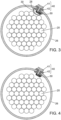
- Each lightning management module 40 consists of a lightning conductor 41 and an insulating fireproof protection 42 element which prevents any direct contact between the lightning conductor 41 and the cable 10.
- the cavity 30 is advantageously destined to receive a grounding element 50 consisting of a conductive cable running all along the cavity from the lightning management modules 40 to the ground.
- the sheath is not provided with a housing and the grounding element 50 is located between the sheath and the bundle of load-bearing tendons.
- the grounding element is provided with an insulating fireproof protection layer or sheathing which allows to protect the cable in case of a lightning bolt although no housing is provided.
- the grounding element 50 is connected to every lightning conductor 41 through an opening made into the sheath 26 and the protective element 42 of the conductor 41.
- This opening is designed so as to prevent any direct contact between any conductive element linked to the lightning conductor 41 and the sheath 26.
- the opening is advantageously covered with the same material than the insulating fireproof protection element so as to impede any contact with the HDPE of the sheath 26.
- the lightning management module has a slab shape. Although only one lightning management module is illustrated, up to six modules can be located on a single section of the cable 10. They can be linked to a single grounding element or, alternatively, each of the up to six elements can be linked to corresponding up to six different grounding elements located in corresponding up to six cavities.
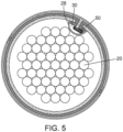
- the lightning management module 40 has a ring shape.
- the lightning conductor consists in a conductive outer ring 41 which is isolated from the sheath by an inner ring 42 made of insulating fireproof material.
- the inner ring corresponds to the insulating fireproof protection element of the invention and the outer ring corresponds to the lightning conductor.
- the outer ring is linked to the grounding element 50 through a pin connection consisting of an insulated opening through the inner ring 42 and the sheath 26.
- the outer ring consists in a ribbon closed onto itself and presenting an outgrowth in the most central and external part of the ring.
- any suitable cross section designed to improve the capacity of the ring to withstand a lightning bolt could be used.
- the housing 28 and the cavity 30 may present different configurations, in particular in terms of cross-section of the housing.
Landscapes
- Engineering & Computer Science (AREA)
- Architecture (AREA)
- Civil Engineering (AREA)
- Structural Engineering (AREA)
- Bridges Or Land Bridges (AREA)
- Installation Of Indoor Wiring (AREA)
- Laying Of Electric Cables Or Lines Outside (AREA)
- Cable Accessories (AREA)
- Communication Cables (AREA)
Claims (9)
- Câble structurel (10) d'un ouvrage de construction, le câble structurel comprenant :un faisceau (20) de tendons porteurs,une gaine (26) à l'intérieur de laquelle est situé le faisceau de tendons,au moins un module de gestion de la foudre (40) consolidé situé sur la gaine (26),dans lequel au moins un module de gestion de la foudre consolidé comprend un paratonnerre (41) et un élément de protection (42) isolant ignifuge,dans lequel l'élément de protection (42) est configuré de manière à empêcher tout contact direct entre le paratonnerre (41) et la gaine (26),dans lequel l'au moins un module de gestion de la foudre (40) consolidé a une parmi une forme de dalle polygonale, une forme de dalle ronde et une forme d'anneau entourant une section de la gaine (26),dans lequel l'au moins un module de gestion de la foudre (40) consolidé est mis à la terre par un matériau conducteur (50) allant de l'au moins un module de gestion de la foudre (40) consolidé à la terre,dans lequel le matériau conducteur de mise à la terre (50) est connecté au paratonnerre (41) de chaque module de gestion de la foudre (40) consolidé à travers une ouverture respective prévue dans la gaine (26) et l'élément de protection (42) dudit au moins un module de gestion de la foudre (40) consolidé.
- Câble structurel selon la revendication 1, dans lequel l'au moins un module de gestion de la foudre consolidé a une forme d'anneau ouvert fermé autour de la gaine.
- Câble structurel selon la revendication 1, dans lequel une pluralité de modules de gestion de la foudre consolidés (42) ayant une forme de dalle polygonale ou ronde sont disposés sur une même section d'une gaine.
- Câble structurel selon la revendication 1, dans lequel l'au moins un module de gestion de la foudre consolidé (42) a une forme de dalle polygonale ou ronde et une taille entre 1 et 10 cm.
- Câble structurel selon l'une quelconque des revendications 1 à 4, dans lequel les au moins un modules de gestion de la foudre (40) consolidés consistent en une pluralité de modules de gestion de la foudre (40), et dans lequel la distance entre deux modules de gestion de la foudre (40) consolidés est entre 1 et 30 mètres, de préférence entre 5 et 25 mètres.
- Câble structurel selon l'une quelconque des revendications 1 à 5, dans lequel le matériau conducteur (50) est situé dans une cavité isolée (30) à l'intérieur de la gaine (26).
- Câble structurel selon la revendication 1, dans lequel le paratonnerre comprend un anneau extérieur (41) conducteur isolé de la gaine (26) par un anneau intérieur (42) correspondant à un élément de protection ignifuge isolant.
- Câble structurel selon la revendication 7, dans lequel l'anneau extérieur (41) est relié à un élément de mise à la terre (50) s'étendant à l'intérieur de la gaine (26) à travers une connexion à broche comportant une ouverture isolée à travers l'anneau intérieur (42) et la gaine (26).
- Câble structurel selon la revendication 7 ou la revendication 8, dans lequel l'anneau extérieur (42) consiste en un ruban fermé sur lui-même et présentant une excroissance dans une partie centrale et externe de celui-ci.
Applications Claiming Priority (1)
| Application Number | Priority Date | Filing Date | Title |
|---|---|---|---|
| PCT/IB2018/001327 WO2020065364A1 (fr) | 2018-09-28 | 2018-09-28 | Module de gestion de la foudre pour câble structurel et procédé et câble structurel correspondants |
Publications (2)
| Publication Number | Publication Date |
|---|---|
| EP3857660A1 EP3857660A1 (fr) | 2021-08-04 |
| EP3857660B1 true EP3857660B1 (fr) | 2023-06-07 |
Family
ID=64556948
Family Applications (1)
| Application Number | Title | Priority Date | Filing Date |
|---|---|---|---|
| EP18811343.5A Active EP3857660B1 (fr) | 2018-09-28 | 2018-09-28 | Module de gestion de la foudre pour câble structurel et procédé et câble structurel correspondants |
Country Status (5)
| Country | Link |
|---|---|
| EP (1) | EP3857660B1 (fr) |
| DK (1) | DK3857660T3 (fr) |
| ES (1) | ES2950627T3 (fr) |
| PT (1) | PT3857660T (fr) |
| WO (1) | WO2020065364A1 (fr) |
Citations (1)
| Publication number | Priority date | Publication date | Assignee | Title |
|---|---|---|---|---|
| WO2018130271A1 (fr) * | 2017-01-10 | 2018-07-19 | Vsl International Ag | Tuyau hybride pour câble de support et son procédé de fabrication |
Family Cites Families (3)
| Publication number | Priority date | Publication date | Assignee | Title |
|---|---|---|---|---|
| DE10233528B4 (de) * | 2002-06-27 | 2008-01-24 | Dehn + Söhne Gmbh + Co. Kg | Blitzstromableiteinrichtung |
| WO2018020288A1 (fr) * | 2016-07-27 | 2018-02-01 | Soletanche Freyssinet | Câble de structure à double gaine |
| MX2019009238A (es) * | 2017-02-03 | 2019-09-19 | Soletanche Freyssinet | Un cable estructural que tiene un alojamiento interior. |
-
2018
- 2018-09-28 WO PCT/IB2018/001327 patent/WO2020065364A1/fr unknown
- 2018-09-28 ES ES18811343T patent/ES2950627T3/es active Active
- 2018-09-28 DK DK18811343.5T patent/DK3857660T3/da active
- 2018-09-28 PT PT188113435T patent/PT3857660T/pt unknown
- 2018-09-28 EP EP18811343.5A patent/EP3857660B1/fr active Active
Patent Citations (1)
| Publication number | Priority date | Publication date | Assignee | Title |
|---|---|---|---|---|
| WO2018130271A1 (fr) * | 2017-01-10 | 2018-07-19 | Vsl International Ag | Tuyau hybride pour câble de support et son procédé de fabrication |
Also Published As
| Publication number | Publication date |
|---|---|
| EP3857660A1 (fr) | 2021-08-04 |
| PT3857660T (pt) | 2023-08-17 |
| WO2020065364A1 (fr) | 2020-04-02 |
| ES2950627T3 (es) | 2023-10-11 |
| DK3857660T3 (da) | 2023-08-07 |
Similar Documents
| Publication | Publication Date | Title |
|---|---|---|
| AU751536B2 (en) | Hybrid electrical-optical cable for overhead installations | |
| US9633766B2 (en) | Energy efficient conductors with reduced thermal knee points and the method of manufacture thereof | |
| US4662712A (en) | Non-metallic self-supporting aerial optical cable | |
| EP3568526B1 (fr) | Tuyau hybride pour câble de support et son procédé de fabrication | |
| US10886036B2 (en) | Energy efficient conductors with reduced thermal knee points and the method of manufacture thereof | |
| US11355263B2 (en) | Insulated submarine cable | |
| US10000899B1 (en) | Fire protection device for a structural cable | |
| EP3577274B1 (fr) | Câble structurel ayant un boîtier interne | |
| US20170001404A1 (en) | Cylindrical thermal protection sheath | |
| JP2018529858A (ja) | 円筒形状の熱保護シースおよびキャップ | |
| EP3857660B1 (fr) | Module de gestion de la foudre pour câble structurel et procédé et câble structurel correspondants | |
| CN208400549U (zh) | 一种抗拉镀锌钢绞线 | |
| EP3026768B1 (fr) | Élément d'espacement phase-terre anti-ratés | |
| CN106024182A (zh) | 一种改进阻燃型架空绝缘电缆 | |
| US20220236036A1 (en) | An armoury element for the protection of a structural material and/or load-carrying element | |
| CN110629660A (zh) | 一种防火及防爆拉索 | |
| RU226362U1 (ru) | Трос несущий изолированный для контактной сети | |
| KR0116313Y1 (ko) | 고압 배전선로용 케이블 다발 | |
| Sharma | Solutions for fibre-optic cables installed on overhead power transmission lines-A review | |
| Bartlett et al. | Integrating optical communications within the power network-the practice | |
| CZ18227U1 (cs) | Zaoblený energetický stožár |
Legal Events
| Date | Code | Title | Description |
|---|---|---|---|
| STAA | Information on the status of an ep patent application or granted ep patent |
Free format text: STATUS: UNKNOWN |
|
| STAA | Information on the status of an ep patent application or granted ep patent |
Free format text: STATUS: THE INTERNATIONAL PUBLICATION HAS BEEN MADE |
|
| PUAI | Public reference made under article 153(3) epc to a published international application that has entered the european phase |
Free format text: ORIGINAL CODE: 0009012 |
|
| STAA | Information on the status of an ep patent application or granted ep patent |
Free format text: STATUS: REQUEST FOR EXAMINATION WAS MADE |
|
| 17P | Request for examination filed |
Effective date: 20210310 |
|
| AK | Designated contracting states |
Kind code of ref document: A1 Designated state(s): AL AT BE BG CH CY CZ DE DK EE ES FI FR GB GR HR HU IE IS IT LI LT LU LV MC MK MT NL NO PL PT RO RS SE SI SK SM TR |
|
| TPAC | Observations filed by third parties |
Free format text: ORIGINAL CODE: EPIDOSNTIPA |
|
| DAV | Request for validation of the european patent (deleted) | ||
| DAX | Request for extension of the european patent (deleted) | ||
| STAA | Information on the status of an ep patent application or granted ep patent |
Free format text: STATUS: EXAMINATION IS IN PROGRESS |
|
| 17Q | First examination report despatched |
Effective date: 20220307 |
|
| GRAP | Despatch of communication of intention to grant a patent |
Free format text: ORIGINAL CODE: EPIDOSNIGR1 |
|
| STAA | Information on the status of an ep patent application or granted ep patent |
Free format text: STATUS: GRANT OF PATENT IS INTENDED |
|
| INTG | Intention to grant announced |
Effective date: 20221213 |
|
| GRAS | Grant fee paid |
Free format text: ORIGINAL CODE: EPIDOSNIGR3 |
|
| GRAA | (expected) grant |
Free format text: ORIGINAL CODE: 0009210 |
|
| STAA | Information on the status of an ep patent application or granted ep patent |
Free format text: STATUS: THE PATENT HAS BEEN GRANTED |
|
| AK | Designated contracting states |
Kind code of ref document: B1 Designated state(s): AL AT BE BG CH CY CZ DE DK EE ES FI FR GB GR HR HU IE IS IT LI LT LU LV MC MK MT NL NO PL PT RO RS SE SI SK SM TR |
|
| REG | Reference to a national code |
Ref country code: GB Ref legal event code: FG4D |
|
| REG | Reference to a national code |
Ref country code: CH Ref legal event code: EP Ref country code: AT Ref legal event code: REF Ref document number: 1577769 Country of ref document: AT Kind code of ref document: T Effective date: 20230615 |
|
| REG | Reference to a national code |
Ref country code: DE Ref legal event code: R096 Ref document number: 602018051355 Country of ref document: DE |
|
| P01 | Opt-out of the competence of the unified patent court (upc) registered |
Effective date: 20230526 |
|
| REG | Reference to a national code |
Ref country code: DK Ref legal event code: T3 Effective date: 20230802 Ref country code: NO Ref legal event code: T2 Effective date: 20230607 |
|
| REG | Reference to a national code |
Ref country code: PT Ref legal event code: SC4A Ref document number: 3857660 Country of ref document: PT Date of ref document: 20230817 Kind code of ref document: T Free format text: AVAILABILITY OF NATIONAL TRANSLATION Effective date: 20230802 |
|
| REG | Reference to a national code |
Ref country code: SE Ref legal event code: TRGR |
|
| REG | Reference to a national code |
Ref country code: LT Ref legal event code: MG9D |
|
| REG | Reference to a national code |
Ref country code: NL Ref legal event code: MP Effective date: 20230607 Ref country code: ES Ref legal event code: FG2A Ref document number: 2950627 Country of ref document: ES Kind code of ref document: T3 Effective date: 20231011 |
|
| PGFP | Annual fee paid to national office [announced via postgrant information from national office to epo] |
Ref country code: NO Payment date: 20230823 Year of fee payment: 6 Ref country code: GB Payment date: 20230823 Year of fee payment: 6 |
|
| REG | Reference to a national code |
Ref country code: GR Ref legal event code: EP Ref document number: 20230401143 Country of ref document: GR Effective date: 20231010 |
|
| REG | Reference to a national code |
Ref country code: AT Ref legal event code: MK05 Ref document number: 1577769 Country of ref document: AT Kind code of ref document: T Effective date: 20230607 |
|
| PG25 | Lapsed in a contracting state [announced via postgrant information from national office to epo] |
Ref country code: RS Free format text: LAPSE BECAUSE OF FAILURE TO SUBMIT A TRANSLATION OF THE DESCRIPTION OR TO PAY THE FEE WITHIN THE PRESCRIBED TIME-LIMIT Effective date: 20230607 Ref country code: NL Free format text: LAPSE BECAUSE OF FAILURE TO SUBMIT A TRANSLATION OF THE DESCRIPTION OR TO PAY THE FEE WITHIN THE PRESCRIBED TIME-LIMIT Effective date: 20230607 Ref country code: LV Free format text: LAPSE BECAUSE OF FAILURE TO SUBMIT A TRANSLATION OF THE DESCRIPTION OR TO PAY THE FEE WITHIN THE PRESCRIBED TIME-LIMIT Effective date: 20230607 Ref country code: LT Free format text: LAPSE BECAUSE OF FAILURE TO SUBMIT A TRANSLATION OF THE DESCRIPTION OR TO PAY THE FEE WITHIN THE PRESCRIBED TIME-LIMIT Effective date: 20230607 Ref country code: HR Free format text: LAPSE BECAUSE OF FAILURE TO SUBMIT A TRANSLATION OF THE DESCRIPTION OR TO PAY THE FEE WITHIN THE PRESCRIBED TIME-LIMIT Effective date: 20230607 |
|
| PGFP | Annual fee paid to national office [announced via postgrant information from national office to epo] |
Ref country code: SE Payment date: 20230822 Year of fee payment: 6 Ref country code: PT Payment date: 20230823 Year of fee payment: 6 Ref country code: GR Payment date: 20230823 Year of fee payment: 6 Ref country code: FR Payment date: 20230822 Year of fee payment: 6 Ref country code: DK Payment date: 20230822 Year of fee payment: 6 Ref country code: DE Payment date: 20230822 Year of fee payment: 6 |
|
| PG25 | Lapsed in a contracting state [announced via postgrant information from national office to epo] |
Ref country code: FI Free format text: LAPSE BECAUSE OF FAILURE TO SUBMIT A TRANSLATION OF THE DESCRIPTION OR TO PAY THE FEE WITHIN THE PRESCRIBED TIME-LIMIT Effective date: 20230607 |
|
| PG25 | Lapsed in a contracting state [announced via postgrant information from national office to epo] |
Ref country code: SK Free format text: LAPSE BECAUSE OF FAILURE TO SUBMIT A TRANSLATION OF THE DESCRIPTION OR TO PAY THE FEE WITHIN THE PRESCRIBED TIME-LIMIT Effective date: 20230607 |
|
| PGFP | Annual fee paid to national office [announced via postgrant information from national office to epo] |
Ref country code: ES Payment date: 20231002 Year of fee payment: 6 |
|
| PG25 | Lapsed in a contracting state [announced via postgrant information from national office to epo] |
Ref country code: IS Free format text: LAPSE BECAUSE OF FAILURE TO SUBMIT A TRANSLATION OF THE DESCRIPTION OR TO PAY THE FEE WITHIN THE PRESCRIBED TIME-LIMIT Effective date: 20231007 |
|
| PG25 | Lapsed in a contracting state [announced via postgrant information from national office to epo] |
Ref country code: SM Free format text: LAPSE BECAUSE OF FAILURE TO SUBMIT A TRANSLATION OF THE DESCRIPTION OR TO PAY THE FEE WITHIN THE PRESCRIBED TIME-LIMIT Effective date: 20230607 Ref country code: SK Free format text: LAPSE BECAUSE OF FAILURE TO SUBMIT A TRANSLATION OF THE DESCRIPTION OR TO PAY THE FEE WITHIN THE PRESCRIBED TIME-LIMIT Effective date: 20230607 Ref country code: RO Free format text: LAPSE BECAUSE OF FAILURE TO SUBMIT A TRANSLATION OF THE DESCRIPTION OR TO PAY THE FEE WITHIN THE PRESCRIBED TIME-LIMIT Effective date: 20230607 Ref country code: IS Free format text: LAPSE BECAUSE OF FAILURE TO SUBMIT A TRANSLATION OF THE DESCRIPTION OR TO PAY THE FEE WITHIN THE PRESCRIBED TIME-LIMIT Effective date: 20231007 Ref country code: EE Free format text: LAPSE BECAUSE OF FAILURE TO SUBMIT A TRANSLATION OF THE DESCRIPTION OR TO PAY THE FEE WITHIN THE PRESCRIBED TIME-LIMIT Effective date: 20230607 Ref country code: CZ Free format text: LAPSE BECAUSE OF FAILURE TO SUBMIT A TRANSLATION OF THE DESCRIPTION OR TO PAY THE FEE WITHIN THE PRESCRIBED TIME-LIMIT Effective date: 20230607 Ref country code: AT Free format text: LAPSE BECAUSE OF FAILURE TO SUBMIT A TRANSLATION OF THE DESCRIPTION OR TO PAY THE FEE WITHIN THE PRESCRIBED TIME-LIMIT Effective date: 20230607 |
|
| PGFP | Annual fee paid to national office [announced via postgrant information from national office to epo] |
Ref country code: CH Payment date: 20231001 Year of fee payment: 6 |
|
| PG25 | Lapsed in a contracting state [announced via postgrant information from national office to epo] |
Ref country code: PL Free format text: LAPSE BECAUSE OF FAILURE TO SUBMIT A TRANSLATION OF THE DESCRIPTION OR TO PAY THE FEE WITHIN THE PRESCRIBED TIME-LIMIT Effective date: 20230607 |
|
| REG | Reference to a national code |
Ref country code: DE Ref legal event code: R097 Ref document number: 602018051355 Country of ref document: DE |
|
| PLBE | No opposition filed within time limit |
Free format text: ORIGINAL CODE: 0009261 |
|
| STAA | Information on the status of an ep patent application or granted ep patent |
Free format text: STATUS: NO OPPOSITION FILED WITHIN TIME LIMIT |
|
| PG25 | Lapsed in a contracting state [announced via postgrant information from national office to epo] |
Ref country code: SI Free format text: LAPSE BECAUSE OF FAILURE TO SUBMIT A TRANSLATION OF THE DESCRIPTION OR TO PAY THE FEE WITHIN THE PRESCRIBED TIME-LIMIT Effective date: 20230607 |
|
| 26N | No opposition filed |
Effective date: 20240308 |
|
| PG25 | Lapsed in a contracting state [announced via postgrant information from national office to epo] |
Ref country code: LU Free format text: LAPSE BECAUSE OF NON-PAYMENT OF DUE FEES Effective date: 20230928 |
|
| REG | Reference to a national code |
Ref country code: BE Ref legal event code: MM Effective date: 20230930 |
|
| PG25 | Lapsed in a contracting state [announced via postgrant information from national office to epo] |
Ref country code: SI Free format text: LAPSE BECAUSE OF FAILURE TO SUBMIT A TRANSLATION OF THE DESCRIPTION OR TO PAY THE FEE WITHIN THE PRESCRIBED TIME-LIMIT Effective date: 20230607 Ref country code: LU Free format text: LAPSE BECAUSE OF NON-PAYMENT OF DUE FEES Effective date: 20230928 Ref country code: IT Free format text: LAPSE BECAUSE OF FAILURE TO SUBMIT A TRANSLATION OF THE DESCRIPTION OR TO PAY THE FEE WITHIN THE PRESCRIBED TIME-LIMIT Effective date: 20230607 Ref country code: MC Free format text: LAPSE BECAUSE OF FAILURE TO SUBMIT A TRANSLATION OF THE DESCRIPTION OR TO PAY THE FEE WITHIN THE PRESCRIBED TIME-LIMIT Effective date: 20230607 |
|
| REG | Reference to a national code |
Ref country code: IE Ref legal event code: MM4A |
|
| PG25 | Lapsed in a contracting state [announced via postgrant information from national office to epo] |
Ref country code: IE Free format text: LAPSE BECAUSE OF NON-PAYMENT OF DUE FEES Effective date: 20230928 |
|
| PG25 | Lapsed in a contracting state [announced via postgrant information from national office to epo] |
Ref country code: IE Free format text: LAPSE BECAUSE OF NON-PAYMENT OF DUE FEES Effective date: 20230928 |
|
| PG25 | Lapsed in a contracting state [announced via postgrant information from national office to epo] |
Ref country code: BE Free format text: LAPSE BECAUSE OF NON-PAYMENT OF DUE FEES Effective date: 20230930 |