EP3857572B1 - Integrierte einquellenkühlung von supraleitenden magneten und hf-spulen in kernspintomografievorrichtungen - Google Patents
Integrierte einquellenkühlung von supraleitenden magneten und hf-spulen in kernspintomografievorrichtungen Download PDFInfo
- Publication number
- EP3857572B1 EP3857572B1 EP19864624.2A EP19864624A EP3857572B1 EP 3857572 B1 EP3857572 B1 EP 3857572B1 EP 19864624 A EP19864624 A EP 19864624A EP 3857572 B1 EP3857572 B1 EP 3857572B1
- Authority
- EP
- European Patent Office
- Prior art keywords
- coils
- stage
- mri
- coil
- cooling
- Prior art date
- Legal status (The legal status is an assumption and is not a legal conclusion. Google has not performed a legal analysis and makes no representation as to the accuracy of the status listed.)
- Active
Links
Images

Classifications
-
- G—PHYSICS
- G01—MEASURING; TESTING
- G01R—MEASURING ELECTRIC VARIABLES; MEASURING MAGNETIC VARIABLES
- G01R33/00—Arrangements or instruments for measuring magnetic variables
- G01R33/02—Measuring direction or magnitude of magnetic fields or magnetic flux
- G01R33/035—Measuring direction or magnitude of magnetic fields or magnetic flux using superconductive devices
-
- G—PHYSICS
- G01—MEASURING; TESTING
- G01R—MEASURING ELECTRIC VARIABLES; MEASURING MAGNETIC VARIABLES
- G01R33/00—Arrangements or instruments for measuring magnetic variables
- G01R33/20—Arrangements or instruments for measuring magnetic variables involving magnetic resonance
- G01R33/28—Details of apparatus provided for in groups G01R33/44 - G01R33/64
- G01R33/32—Excitation or detection systems, e.g. using radio frequency signals
- G01R33/34—Constructional details, e.g. resonators, specially adapted to MR
- G01R33/34015—Temperature-controlled RF coils
- G01R33/3403—Means for cooling of the RF coils, e.g. a refrigerator or a cooling vessel specially adapted for housing an RF coil
-
- G—PHYSICS
- G01—MEASURING; TESTING
- G01R—MEASURING ELECTRIC VARIABLES; MEASURING MAGNETIC VARIABLES
- G01R33/00—Arrangements or instruments for measuring magnetic variables
- G01R33/20—Arrangements or instruments for measuring magnetic variables involving magnetic resonance
-
- G—PHYSICS
- G01—MEASURING; TESTING
- G01R—MEASURING ELECTRIC VARIABLES; MEASURING MAGNETIC VARIABLES
- G01R33/00—Arrangements or instruments for measuring magnetic variables
- G01R33/20—Arrangements or instruments for measuring magnetic variables involving magnetic resonance
- G01R33/28—Details of apparatus provided for in groups G01R33/44 - G01R33/64
- G01R33/38—Systems for generation, homogenisation or stabilisation of the main or gradient magnetic field
- G01R33/3804—Additional hardware for cooling or heating of the magnet assembly, for housing a cooled or heated part of the magnet assembly or for temperature control of the magnet assembly
-
- G—PHYSICS
- G01—MEASURING; TESTING
- G01R—MEASURING ELECTRIC VARIABLES; MEASURING MAGNETIC VARIABLES
- G01R33/00—Arrangements or instruments for measuring magnetic variables
- G01R33/20—Arrangements or instruments for measuring magnetic variables involving magnetic resonance
- G01R33/28—Details of apparatus provided for in groups G01R33/44 - G01R33/64
- G01R33/38—Systems for generation, homogenisation or stabilisation of the main or gradient magnetic field
- G01R33/381—Systems for generation, homogenisation or stabilisation of the main or gradient magnetic field using electromagnets
- G01R33/3815—Systems for generation, homogenisation or stabilisation of the main or gradient magnetic field using electromagnets with superconducting coils, e.g. power supply therefor
-
- G—PHYSICS
- G01—MEASURING; TESTING
- G01R—MEASURING ELECTRIC VARIABLES; MEASURING MAGNETIC VARIABLES
- G01R33/00—Arrangements or instruments for measuring magnetic variables
- G01R33/20—Arrangements or instruments for measuring magnetic variables involving magnetic resonance
- G01R33/44—Arrangements or instruments for measuring magnetic variables involving magnetic resonance using nuclear magnetic resonance [NMR]
- G01R33/46—NMR spectroscopy
-
- H—ELECTRICITY
- H01—ELECTRIC ELEMENTS
- H01F—MAGNETS; INDUCTANCES; TRANSFORMERS; SELECTION OF MATERIALS FOR THEIR MAGNETIC PROPERTIES
- H01F6/00—Superconducting magnets; Superconducting coils
-
- H—ELECTRICITY
- H01—ELECTRIC ELEMENTS
- H01F—MAGNETS; INDUCTANCES; TRANSFORMERS; SELECTION OF MATERIALS FOR THEIR MAGNETIC PROPERTIES
- H01F6/00—Superconducting magnets; Superconducting coils
- H01F6/04—Cooling
-
- H—ELECTRICITY
- H01—ELECTRIC ELEMENTS
- H01F—MAGNETS; INDUCTANCES; TRANSFORMERS; SELECTION OF MATERIALS FOR THEIR MAGNETIC PROPERTIES
- H01F6/00—Superconducting magnets; Superconducting coils
- H01F6/06—Coils, e.g. winding, insulating, terminating or casing arrangements therefor
-
- F—MECHANICAL ENGINEERING; LIGHTING; HEATING; WEAPONS; BLASTING
- F25—REFRIGERATION OR COOLING; COMBINED HEATING AND REFRIGERATION SYSTEMS; HEAT PUMP SYSTEMS; MANUFACTURE OR STORAGE OF ICE; LIQUEFACTION SOLIDIFICATION OF GASES
- F25B—REFRIGERATION MACHINES, PLANTS OR SYSTEMS; COMBINED HEATING AND REFRIGERATION SYSTEMS; HEAT PUMP SYSTEMS
- F25B9/00—Compression machines, plants or systems, in which the refrigerant is air or other gas of low boiling point
- F25B9/10—Compression machines, plants or systems, in which the refrigerant is air or other gas of low boiling point with several cooling stages
Definitions
- This application relates generally to devices that are based on Nuclear Magnetic Resonance (NMR). More specifically, this application relates to a system for cooling superconducting magnets and Radio Frequency (RF) coils with a single integrated cooling system in an NMR device, where the system is defined by the features of claim 1.
- NMR Nuclear Magnetic Resonance
- RF Radio Frequency
- NMR Nuclear magnetic resonance
- NMR is a physical phenomenon in which nuclei in a magnetic field absorb and re-emit electromagnetic radiation (signal).
- the signal is a function of specific resonance frequency which depends on the strength of the magnetic field and the magnetic properties of the isotope of specific atoms.
- NMR phenomenon is at the core of MRI scanners and NMR spectrometers.
- subjects are placed in background fields of power magnets generating fields of 0.5 to 20 T, or even higher.
- Radiofrequency coils (RF coils) are used as transmitters, receivers, and sometimes also as tranceivers, of radiofrequency (RF) signals in NMR devices.
- High resolution MRI scanners and NMR spectrometer use superconducting magnets to facilitate the generation of strong signal, and specially designed RF coils to generate strong RF signal.
- MRI scanners are used as examples to describe method of improving their performance.
- the methods described in this disclosure apply equally to both MRI scanners and NMR spectrometers.
- Nuclear Magnetic Resonance is a physical phenomenon in which nuclei in a magnetic field absorb and re-emit electromagnetic radiation. This energy is at a specific resonance frequency which depends on the strength of the magnetic field and the magnetic properties of the isotope of the atoms; in practical applications, the frequency is similar to VHF and UHF television broadcasts (60-1000 MHz). NMR allows the observation of specific quantum mechanical magnetic properties of the atomic nucleus. Many scientific techniques exploit NMR phenomena to study molecular physics, crystals, and non-crystalline materials through NMR spectroscopy. NMR is also routinely used in advanced medical imaging techniques, such as in magnetic resonance imaging (MRI).
- MRI magnetic resonance imaging
- Radiofrequency coils are the transmitters, receivers, and sometimes as dual purpose transmit-and-receives, of radiofrequency (RF) signals in the magnetic resonance imaging (MRI).
- the MR signal in MRI is produced by the process of resonance, which is the result of radiofrequency coils. They consist of two electromagnetic coils, the transmitter and receiver coils generating and receiving electromagnetic fields. Atomic nuclei of interest in MRI studies have their own resonant frequencies, in the radiofrequency portion of the electromagnetic spectrum.
- a method for obtaining imaging data from human head and brain using a Head-scanning MRI (HMRI) system configured to provide highly accurate images with high Signal-to-Noise Ratio (SNR or S/N) using superconducting magnets of moderate field strengths primarily in the range of 0.5 Tesla (T) to 1.5 T, but also applicable, to various extents, to other field strengths outside this range.
- HMRI Head-scanning MRI
- the HMRI may include a scanning bore deployed within an actively or passively shielded, Cryogen-Free (CF), conduction-cooled superconducting magnet.
- CF Cryogen-Free
- the CF magnet uses a two stage cryocooler, in which a first stage cools a certain part of the magnet system (target first-stage body to be cooled, like the radiation shield of the superconducting magnet) down to a mid-level temperature range, such as 30-85 degrees Kelvin (K), and the second stage cools certain other parts of the superconducting magnet (target second-stage body to be cooled like the cold mass of the superconducting magnet) further down to lower temperature range, for example, about 3-20 degrees K, near absolute zero temperature.
- a first stage cools a certain part of the magnet system (target first-stage body to be cooled, like the radiation shield of the superconducting magnet) down to a mid-level temperature range, such as 30-85 degrees Kelvin (K)
- K degrees Kelvin
- the first stage of the two-stage CF magnet system is used to cool both the target body and the receiving RF coil to create a higher SNR relative to when RF coils are not cooled.
- cooling substrates made from sapphire are used to cool the RF coils by conduction because sapphire conducts heat efficiently but not electricity, hence it cools but does not increase or contribute to generation of electromagnetic noise.
- a vacuum vessel of the CF magnet in which the superconducting magnet is deployed, is configured to have a patient bore as well as an annulus to allow fitting of gradient coil.
- the vacuum vessel wall separating the patient bore and the vacuum space is made from a material that is electrically non-conducting so that the said wall doesn't contribute to generation of electromagnetic noise.
- MRI is a technique for accurate and high-resolution visualization of interior of animal tissues among other applications. This technique is based on the Nuclear Magnetic Resonance (NMR) property.
- NMR Nuclear Magnetic Resonance
- MRI is often implemented in the form of a scanning device or scanner in which the patient lies horizontally or is positioned within a scanning bore (see Figure 1 ) of sufficient size to accommodate the whole body or parts of the body of the patient, such as limbs or head.
- the main components of an MRI scanning system include a scanning bore surrounded by various devices including a primary field magnet, usually a superconducting electromagnet, including several superconducting coils, generating a powerful static and stable magnetic field that surrounds the patient positioned within the scanning bore.
- the static magnetic field aligns atomic nuclei in the patient's tissues in the direction of the magnetic field.
- the MRI system further includes one or two sets of Radio Frequency (RF) coils for transmitting, receiving, or both, a set of magnetic gradient coils, an active or passive magnetic shield, and various mechanical and thermal insulation components that enable the superconducting magnet to have structural integrity and remain cold.
- RF Radio Frequency
- Other mechanical, electrical and software components are used in conjunction with the above components to create a working MRI system.
- the hydrogen (H) atoms contained in the soft tissue align in the direction of the static magnetic field, along the axis of the scanning bore of the MRI.
- an RF pulse which is frequency-tuned to the static magnetic field is generated by the RF transmit coil to create resonance in the H atoms.
- the alignment directions (or state) of the H molecules are changed by the RF pulse.
- the RF pulse ends, the alignment of H atoms reverts to its original state while at the same time emitting signals.
- the RF receive coil picks up the emitted signals and sends to a computer for conversion to an image using mathematical calculations such as Fourier Transform.
- An assemblage of magnetic gradient coil which usually includes three sets (one set for each dimension of space), collectively often called gradient coil, are used to encode the magnetic field in the bore of the magnet so that RF signals emitted from H atoms can be referenced to where the atoms are located within the bore of the magnet.
- the MRI image is subsequently constructed with computer software based on the known and detected changes in the magnetic field and RF signal, allowing for spatial information needed to construct an image to be recovered from the measured signals using various mathematical techniques, such as Fourier analysis.
- various mathematical techniques such as Fourier analysis.
- two Dimensional (2D) images or 3D volumes can be obtained in any arbitrary orientation.
- MRI in part uses the fact that body tissue contains a large proportion of water, and hence protons (Hydrogen nuclei), the orientation of which are aligned in a particular direction when placed within a large static magnetic field.
- protons Hydrogen nuclei
- Each water molecule has two hydrogen nuclei or protons.
- the average magnetic moment of many protons becomes aligned with the direction of the field.
- RF transmitter coils are used to produce a momentary RF varying electromagnetic field with a resonance frequency, which changes or flips the spin of the protons. After the RF coils are turned off, the varying magnetic field disappears causing the spins of the protons to return to their original states and be re-aligned with the static magnetic field. This return to original spin state is called relaxation.
- an RF signal is generated by the change in the spin, which can be detected by instruments such as receiver RF coils.
- 3D information about the origin of the signal in the body may be obtained by applying additional gradient magnetic fields. These known additional gradient magnetic fields may be applied to specify the location from which RF signal is received.
- MRI Magnetic resonance Imaging
- MRI Magnetic resonance Imaging
- Imaging by an MRI scanner requires a very uniform, constant, and stable magnetic field over a specific volume.
- a magnetic field often referred to as a B 0 field
- MRI devices that use permanent magnets typically generate a B 0 magnetic field of less than one Tesla (T).
- T Tesla
- superconducting electromagnets producing higher magnetic fields are used.
- high resolution human MRI scanners use magnets that generate fields of 0.5 T or higher.
- superconducting MRI magnets that generate a field of higher than 0.5 T have a cylindrical bore for equipment and patient access (patient bore).
- Open MRI machines (which do not have a tubular bore that is closed on all sides except its two ends, to contain the patient or body parts) can also achieve 0.5 T and even 1 T, but become proportionally large, heavy, and expensive to buy, install, and operate. If the patient bore is large enough to allow for the whole human body to fit through the scanner, it is referred to as a whole body scanner. Such scanners are large and expensive. There are certain other smaller scanners that have smaller bores, allowing the extremities, head, arms and legs, to fit through. These scanners, referred to as head-scanners and extremities scanners, are smaller and less expensive but offer acceptable scanning over the head, or arms and legs.
- the magnetic fields of superconducting magnets with cylindrical bores are typically generated by a number of solenoid type superconducting coils within the overall superconducting magnet.
- Superconducting B 0 magnets use coils that need to be maintained at cryogenic temperatures that are lower than the critical temperature of the superconducting coils to allow superconductor mode of the coil material to appear, in which electrical resistance is zero.
- the coils of a superconducting MRI magnet operate in a pool of liquid helium, at close to atmospheric pressure that keeps the coils at about 4.2 K.
- cryocooler that is physically and thermally connected to the coils by solid materials that conduct heat away from the coils.
- these types of magnets are called cryogen-free (CF) or conduction-cooled magnets.
- One of the customary methods of achieving a substantially constant magnetic field is to operate the superconducting magnet of an MRI system in a "Persistent Mode," in which mode the current circulates, almost perpetually, without applying further power, through a substantially zero-resistance closed-loop set of coils.
- the advantage of the persistent mode is the constancy of the magnetic field, which is better than what can be achieved in a normal, driven, or non-persistent mode of operation (in which mode power is applied to maintain the current), even with the best regulated power supplies. Furthermore, in the persistent mode no additional energy is needed to power the windings and, therefore, the power supply can be turned off.
- MRI scanners are used and operated within an area where the magnetic field outside of the area is less than 5 Gauss.
- the area inside of the 5 Gauss line is sometimes called the MRI magnet's 5-Gauss footprint.
- superconducting magnets used in MRI applications are magnetically shielded to minimize the 5-Gauss footprint.
- MRI superconducting magnets may be shielded actively or passively.
- all field coils and shielding coils, as well as the persistent mode switch coil are connected in series by superconducting electrical joints.
- the shield coils are connected to the rest of coils such that the sense of the currents (direction of current flow) in the shielding coils are opposite those of the other coils.
- the quality and resolution of MRI-generated image depends on a number of factors.
- One factor is a strong, uniform, and stable primary field generated by the primary superconducting magnet.
- the stronger the field the higher the SNR and the better the resolution and quality of the resulting image.
- increasing the strength of the primary magnetic field from 0.5 T to 1.5 T improves SNR.
- Further increase in the primary magnetic field for example, up to 3 T leads to higher SNR.
- more powerful magnets are also more expensive, bigger, heavier, and face more limitations in choice of installation sites.
- Another factor that affects SNR is the electrical conductivity of the NMR probe, or receiver RF coil, used to detect signals generated during the relaxation process.
- the electrical conductivity of preferred RF coil materials for example copper
- SNR Signal to Noise Ratio
- the transmitter RF coil may remain at room temperature or cryogenic temperatures.
- the gain in SNR is mostly associated with conductivity of the receiver RF coil.
- a smaller primary magnetic field, B0 may be used to obtain the same image quality as a more powerful primary magnet and a non-cooled RF coil.
- cooling the probe (receiver RF coil) made from high purity copper to about 40 degrees K using a first stage of the two-stage cryocooler, may, in principle, increase electrical conductivity by a factor of about 20, which may create multiple times or significant increase in SNR.
- Figure 1 shows an example arrangement for using a Magnetic Resonance Imaging (MRI) system for medical diagnostics.
- a diagnostic arrangement 100 includes a whole-body MRI scanner 102 having a scanning bore 104, which is a tunnel-like opening, to accommodate the whole body of a patient 106 lying on a bed 108.
- the bed 108 slides into the opening 104 to position the appropriate portion of the patient's body within the MRI magnet system to start the scanning process.
- the first stage of a two-stage cryocooler cold-head used in MRI CF magnets operates at about 40-60° K and can remove about 30-50 Watts (W) of heat
- the second stage operates at about 4-6 ° K and can remove additional about 1-2 W of heat.
- W Power
- the entire cooling power of the two stages of the cryocooler cold-head is no longer needed.
- some of the extra cooling power of the first stage or the second stages of the same cryocooler may be used to cool the RF coil and some of its electronics.
- the conductivity of copper that typically makes up the RF receiver coil increases by a factor of about 20 when at 40K and a factor of 4 when at 80K, thereby allowing for higher signal-noise ratio and therefore high resolution for the MRI scanner. If the second stage of the cryocooler cold-head were used to cool the RF receive coil to even lower temperatures than 40 K then the conductivity of copper improves further and therefore further improvements in SNR would be achievable.
- the present disclosure further teaches that conduction of heat from the RF coil and its electronics may be advantageously accomplished by heat conduction members made from sapphire, including sapphire fibers and composite members that include sapphire.
- Sapphire may be chosen for its high heat conductivity relative to other material while at the same time lacking electrical conductivity. The low or non-existent electrical conductivity reduces or substantially eliminates the generation of eddy current by the heat conducting members.
- the heat conduction may be via composite materials made from Litz copper wires or cables similar to those discussed by Pourrahimi in patent US 8,275,429 .
- Litz copper wire/cable is chosen for its high heat conductivity and generation of low levels of eddy current within the heat conducting members. The elimination of eddy currents reduces electrical noise and thus increases SNR.
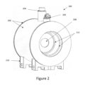
- FIG. 2 shows an example configuration of an HMRI system for medical diagnostics having an integral cooling system for cooling both the superconducting magnet and RF coils.
- MRI magnet system 200 includes body enclosure or vacuum vessel 202 (cryostat), cooling port with cryocooler cold-head 204, instrument and vacuum port 206, scanning bore 208, support structure 210, and asymmetric gradient coil 212 fitted inside an annulus designed as part of the exterior of the vacuum vessel 202.
- the cryocooler cold-head 204 is a two-stage cryocooler cold-head connected to the first stage body and second stage body within the enclosure 202 to conduct heat away from the overall superconducting magnet. Radiation shield (part of the target first stage body) and vacuum created inside the enclosure 202 substantially reduce heat transfer between the cold-mass and the external environment in which the MRI system is placed. Hence, the only mode of heat transfer is conduction via cold-head 204.
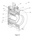
- FIG. 3 shows a perspective cross-section of the example HMRI system of Figure 2 .
- MRI magnet system cross-section 300 shows external enclosure or vacuum vessel 302 (cryostat), non-conducting magnet cryostat bore 304, gradient coil 306, first stage of cryocooler 310, second stage of cryocooler 312, heat-conducting tubular member 314, sapphire heat exchanger 316 bonded to non-conducting tubular member 318 and extended over and bonded to tubular member 314, receiver RF coils 320, inner layer and radiation shield 324 of cryostat 302, and superconducting coils 326 that is a part of the cold mass 328.
- cryostat cryostat
- non-conducting magnet cryostat bore 304 shows external enclosure or vacuum vessel 302 (cryostat), non-conducting magnet cryostat bore 304, gradient coil 306, first stage of cryocooler 310, second stage of cryocooler 312, heat-conducting tubular member 314, sapphire heat exchanger
- FIG. 3 shows an example of HMRI with a closed end bore. Those skilled in the art realize that the present disclosure applies to open bore HMRI as well.
- a number of elements are needed. These elements include a strong, uniform, and stable primary field, RF transmitter coils, magnetic gradient coil, and cooled RF receiver coils. In some embodiments, the same RF coil may be used as both a transmitter RF coil and a receiver RF coil. Cooling both the first stage body, which includes the optional radiation shield, and the receiver RF coils by conduction by the first stage of the cryocooler cold-head 310 allows the RF receiver coils to cool to temperature of 40-80 K, resulting in a clearer MRI image than without cooling the receiver RF coils.
- cryostat 302 is a vessel which is pumped to create a vacuum inside to substantially prevent convective and heat transfer through space within the cryostat.
- radiation shield 324 radiative mode of heat transfer to the cold-mass is also substantially reduced. This leaves heat conduction via solid members and electrical instrumentation wiring as the only paths for heat transfer to the radiation shield and the cold-mass.
- cryostat the major, but not the only, components needed for mechanical support and cooling down the first stage body of the magnet system (radiation shield), the receiver RF coils 320, and the second stage body (cold-mass) of the CF magnet system, to their operating temperatures using the two-stage cryocooler.
- the configuration of the thermal and physical connections between the cryocooler cold-head and the first stage body, RF coils, and the second stage body may vary in details, but direct or indirect strategic physical thermal connections are needed to cool these components.
- the first stage 310 of the cryocooler cold-head is physically coupled with the radiation shield 324, and the second stage 312 of the cold-head is physically coupled with the cold-mass 328.
- the first stage may cool the radiation shield down to about 40-80° K, while the second stage may further cool down the cold-mass to about 3-6° K.
- the first stage is also strategically coupled to the receiver RF coils 320, via the radiation shield 324, to the heat-conducting tubular member 314, further connected to non-conducting tube 318, further connected to bars or sheets of heat-conducting but not electricity-conducting material 316, such as sapphire, as shown. Sapphire, or other material with similar properties are used to remove heat from the receiver RF coils 320 and their wiring to cool them down, while at the same time substantially not conducting electricity to reduce electrical noise and increase SNR.
- receiver RF coils 320 With this cooling configuration, in operation, heat is removed from receiver RF coils 320 by thermal conduction via sapphire bars 316 to conductive tube 314, to radiation shield 324, and eventually to the first stage cold-head 310. This way the receiver RF coil is cooled down to about 40-80° K, improving SNR.
- the cold-mass 328, which includes the superconducting coils 326 are cooled via the second stage 312 of the cryocooler down to 3-6 K.
- the gradient coil 306 may be symmetrical or asymmetrical in design, and therefore the physical configuration.
- the asymmetrical gradient coil, shown in Figure 3 may have two sections, each with a different internal diameter, creating a geometric discontinuity like a step between the two sections, as shown in Figure 3 .
- the bigger diameter section can accommodate a patient's shoulders while the head is placed inside the scanning bore 304.
- the MRI system may be specialized for head and brain scanning. Such an MRI system will be more compact relative to full body scanners and will be more readily available and affordable to medical clinics and research institutes.
- the cooling system may include a single-stage cryocooler physically coupled with both an optional radiation shield, the cold-mass, and the receiver RF coils to cool them.
- the cooling system may include two or more cooling stages in which all or some of the cooling stages may be physically coupled with both or one of the primary field magnet and the receiver RF coils.
- the common method in all these examples is that at least one of the stages of the same cryocooler cold-head, regardless of the number of cooling stages it may have and how such stages may be coupled with the cold-masses, cools the target body to be cooled as well as the receiver RF coils to increase SNR. This approach to increasing SNR reduces both the complexity and the cost of high resolution MRI scanners.
- both the target body to be cooled for example first stage body that is often the radiation shield, and the receiver RF coils are cooled by the first stage of the cryocooler cold-head to temperatures of 40-80 K, achieving higher SNR relative to non-cooled receiver RF coils.
- the second stages of a cryocooler cold-head cools cold-mass of the magnet systems that included the superconducting coils to about 3-6 K, and the RF receive coils to temperatures below 40 K, achieving even higher SNR relative to non-cooled receiver RF coils.
Landscapes
- Physics & Mathematics (AREA)
- Condensed Matter Physics & Semiconductors (AREA)
- General Physics & Mathematics (AREA)
- Engineering & Computer Science (AREA)
- Power Engineering (AREA)
- Thermal Sciences (AREA)
- Electromagnetism (AREA)
- Spectroscopy & Molecular Physics (AREA)
- High Energy & Nuclear Physics (AREA)
- Magnetic Resonance Imaging Apparatus (AREA)
Claims (5)
- Magnetresonanztomografie-(MRT)-Magnetsystem mit Bilderzeugungsfähigkeit bei hohem Signal-Rausch-Verhältnis (SRV), wobei das System Folgendes umfasst:einen äußeren Vakuumbehälter (202) mit einer Patientenöffnung (104) und einem Ring für eine Gradientenspule (212),einen von dem Vakuumbehälter (202) umschlossenen Hauptteil der ersten Stufe,einen von dem Hauptteil der ersten Stufe umschlossenen Hauptteil der zweiten Stufe mit supraleitenden Spulen (326),eine RF-Transceiverspule oder eine Radiofrequenzsenderspule (RF-Senderspule) und eine RF-Empfängerspule (320), die in dem Hauptteil der ersten Stufe angeordnet sind, wobei der Hauptteil der ersten Stufe und die RF-Spulen und der Hauptteil der zweiten Stufe gemeinsam von dem Vakuumbehälter (202) umschlossen sind, undeinen Kryokühler (310) mit zumindest einer ersten und einer zweiten Stufe, der mit dem Vakuumbehälter (202) gekoppelt ist, wobei die erste Stufe (310) so konfiguriert ist, dass sie den Hauptteil der ersten Stufe und den RF-Empfänger oder die RF-Empfängerspulen auf eine Temperatur von T1 Grad kühlt, und die zweite Stufe (312) so konfiguriert ist, dass sie den Hauptteil der zweiten Stufe auf eine Temperatur von T2 Grad kühlt, und wobei T1 > T2.
- System nach Anspruch 1, wobei die Temperatur T1 zwischen 30 und 85 Grad K und die Temperatur T2 zwischen 3 und 20 Grad K liegt.
- System nach Anspruch 1, wobei die erste Stufe (310) des Kryokühlers auch die RF-Senderspule kühlt.
- System nach Anspruch 1, das ferner ein Kühlsubstrat zum Leitungskühlen der RF-Empfängerspule aufweist, wobei das Kühlsubstrat zwar wärmeleitend, aber elektrisch im Wesentlichen nichtleitend ist.
- System nach Anspruch 4, wobei es sich bei dem Kühlsubstrat um Saphir oder Saphirverbundstoffe handelt.
Applications Claiming Priority (2)
| Application Number | Priority Date | Filing Date | Title |
|---|---|---|---|
| US16/140,466 US11009572B2 (en) | 2018-09-24 | 2018-09-24 | Integrated single-sourced cooling of superconducting magnets and RF coils in nuclear magnetic resonance devices |
| PCT/US2019/052513 WO2020068708A1 (en) | 2018-09-24 | 2019-09-23 | Integrated single-sourced cooling of superconducting magnets and rf coils in nuclear magnetic resonance devices |
Publications (5)
| Publication Number | Publication Date |
|---|---|
| EP3857572A1 EP3857572A1 (de) | 2021-08-04 |
| EP3857572A4 EP3857572A4 (de) | 2023-03-01 |
| EP3857572C0 EP3857572C0 (de) | 2025-04-23 |
| EP3857572B1 true EP3857572B1 (de) | 2025-04-23 |
| EP3857572B8 EP3857572B8 (de) | 2025-06-04 |
Family
ID=69885410
Family Applications (1)
| Application Number | Title | Priority Date | Filing Date |
|---|---|---|---|
| EP19864624.2A Active EP3857572B8 (de) | 2018-09-24 | 2019-09-23 | Integrierte einquellenkühlung von supraleitenden magneten und hf-spulen in kernspintomografievorrichtungen |
Country Status (6)
| Country | Link |
|---|---|
| US (1) | US11009572B2 (de) |
| EP (1) | EP3857572B8 (de) |
| CN (2) | CN118098750A (de) |
| AU (1) | AU2019347727B2 (de) |
| CA (1) | CA3113951A1 (de) |
| WO (1) | WO2020068708A1 (de) |
Families Citing this family (8)
| Publication number | Priority date | Publication date | Assignee | Title |
|---|---|---|---|---|
| US11221382B2 (en) * | 2017-10-06 | 2022-01-11 | Advanced Imaging Research, Inc. | Optimized infant MRI system with cryocooled RF coil |
| US11543476B2 (en) * | 2020-08-06 | 2023-01-03 | Chengdu Yijian Medical Technology Co., Ltd | Conduction-cooled radiofrequency coil subsystem and magnetic resonance imaging magnet system having the same |
| CN112630710A (zh) * | 2020-11-03 | 2021-04-09 | 成都易检医疗科技有限公司 | 冷却装置、系统及磁共振设备 |
| CN112433188A (zh) * | 2020-11-27 | 2021-03-02 | 中国科学院深圳先进技术研究院 | 用于射频线圈的冷却系统、磁共振成像设备 |
| CN114252929B (zh) * | 2021-11-23 | 2024-11-22 | 山东能源集团有限公司 | 一种矿井底板水源核磁共振探测装置及其工作方法 |
| CN117767691A (zh) * | 2022-09-22 | 2024-03-26 | 空中客车简化股份公司 | 改进的超导电机定子、飞行器超导电机及飞行器 |
| EP4343355A1 (de) * | 2022-09-23 | 2024-03-27 | Siemens Healthcare Limited | Kryogengekühlte supraleitende magnetanordnung für einen magnetresonanzbildgebungsscanner |
| DE102023204264A1 (de) * | 2023-05-09 | 2024-11-14 | Siemens Healthineers Ag | Computerimplementiertes Verfahren zum Betrieb einer Magnetresonanzeinrichtung, Magnetresonanzeinrichtung, Computerprogramm und elektronisch lesbarer Datenträger |
Family Cites Families (9)
| Publication number | Priority date | Publication date | Assignee | Title |
|---|---|---|---|---|
| DE4013111C2 (de) * | 1990-04-25 | 1994-05-26 | Spectrospin Ag | HF-Empfangsspulenanordnung für NMR-Spektrometer |
| GB0401835D0 (en) * | 2004-01-28 | 2004-03-03 | Oxford Instr Superconductivity | Magnetic field generating assembly |
| US20050179512A1 (en) * | 2004-02-12 | 2005-08-18 | Ge Medical Systems Global Technology Company, Llc | Mri system with liquid cooled rf space |
| US8253416B2 (en) * | 2009-03-10 | 2012-08-28 | Time Medical Holdings Company Limited | Superconductor magnetic resonance imaging system and method (super-MRI) |
| US8275429B1 (en) | 2010-04-08 | 2012-09-25 | Stern Magnetics, LLC | High magnetic field gradient strength superconducting coil system |
| US8729894B2 (en) * | 2010-07-30 | 2014-05-20 | General Electric Company | System and method for operating a magnetic resonance imaging system during ramping |
| US8676282B2 (en) * | 2010-10-29 | 2014-03-18 | General Electric Company | Superconducting magnet coil support with cooling and method for coil-cooling |
| RU2013154560A (ru) * | 2011-05-10 | 2015-06-20 | Тайм Медикал Холдингз Компани Лимитед | Компоновка rf катушек всего тела, имеющих криогенное охлаждение, и система mri с такой компоновкой |
| US20180151280A1 (en) * | 2016-11-25 | 2018-05-31 | Shahin Pourrahimi | Pre-cooling and increasing thermal heat capacity of cryogen-free magnets |
-
2018
- 2018-09-24 US US16/140,466 patent/US11009572B2/en active Active
-
2019
- 2019-09-23 CN CN202410234008.8A patent/CN118098750A/zh active Pending
- 2019-09-23 AU AU2019347727A patent/AU2019347727B2/en active Active
- 2019-09-23 EP EP19864624.2A patent/EP3857572B8/de active Active
- 2019-09-23 CN CN201980066269.0A patent/CN112840415A/zh active Pending
- 2019-09-23 WO PCT/US2019/052513 patent/WO2020068708A1/en not_active Ceased
- 2019-09-23 CA CA3113951A patent/CA3113951A1/en active Pending
Also Published As
| Publication number | Publication date |
|---|---|
| US11009572B2 (en) | 2021-05-18 |
| US20200096581A1 (en) | 2020-03-26 |
| AU2019347727A1 (en) | 2021-05-06 |
| WO2020068708A1 (en) | 2020-04-02 |
| EP3857572C0 (de) | 2025-04-23 |
| EP3857572A4 (de) | 2023-03-01 |
| EP3857572B8 (de) | 2025-06-04 |
| CA3113951A1 (en) | 2020-04-02 |
| CN112840415A (zh) | 2021-05-25 |
| AU2019347727B2 (en) | 2025-04-17 |
| EP3857572A1 (de) | 2021-08-04 |
| CN118098750A (zh) | 2024-05-28 |
Similar Documents
| Publication | Publication Date | Title |
|---|---|---|
| EP3857572B1 (de) | Integrierte einquellenkühlung von supraleitenden magneten und hf-spulen in kernspintomografievorrichtungen | |
| CN102483447B (zh) | 包含超导主磁体、超导梯度场线圈和冷却rf线圈的mri系统 | |
| US7777491B2 (en) | Magnetic resonance coil system | |
| US7772842B2 (en) | Dedicated superconductor MRI imaging system | |
| RU2572650C2 (ru) | Модуль с градиентными катушками из сверхпроводника с криогенным охлаждением для магнитно-резонансной томографии | |
| Kathiravan et al. | A review on potential issues and challenges in MR imaging | |
| US5185576A (en) | Local gradient coil | |
| US7728592B2 (en) | Integrated superconductor MRI imaging system | |
| US7498810B2 (en) | Systems, methods and apparatus for specialized magnetic resonance imaging with dual-access conical bore | |
| US7084629B2 (en) | Parallel imaging compatible birdcage resonator | |
| WO2006075213A2 (en) | Nmr mas probe with cryogenically cooled critical circuit components | |
| EP2483702A2 (de) | Mr-bildgebungssystem mit frei zugänglichem untersuchungsvolumen | |
| JP2005152632A (ja) | 補助的な静磁場成形コイルを利用するmriシステム | |
| JPH0479304A (ja) | 超電導マグネット装置 | |
| DE102021205916A1 (de) | Magnetresonanzvorrichtung mit einer thermisch gekoppelten Hochfrequenzeinheit | |
| Ginefri et al. | Technical aspects: development, manufacture and installation of a cryo-cooled HTS coil system for high-resolution in-vivo imaging of the mouse at 1.5 T | |
| Wang | Hardware of mri system | |
| US8598877B2 (en) | System and method for coil disabling in magnetic resonance imaging | |
| US7250764B2 (en) | Shielded dome resonator for MR scanning of a cerebrum | |
| Hu et al. | A Novel Receive-Only Liquid Nitrogen ($\hbox {LN} _ {2} $)-Cooled RF Coil for High-Resolution In Vivo Imaging on a 3-Tesla Whole-Body Scanner | |
| US20180151280A1 (en) | Pre-cooling and increasing thermal heat capacity of cryogen-free magnets | |
| Felder et al. | MRI Instrumentation | |
| JP4503405B2 (ja) | 超電導磁石装置及びこれを用いた磁気共鳴イメージング装置 | |
| Sattarov et al. | New magnet technology for a 1.5 T open-MRI breast imager |
Legal Events
| Date | Code | Title | Description |
|---|---|---|---|
| STAA | Information on the status of an ep patent application or granted ep patent |
Free format text: STATUS: THE INTERNATIONAL PUBLICATION HAS BEEN MADE |
|
| PUAI | Public reference made under article 153(3) epc to a published international application that has entered the european phase |
Free format text: ORIGINAL CODE: 0009012 |
|
| STAA | Information on the status of an ep patent application or granted ep patent |
Free format text: STATUS: REQUEST FOR EXAMINATION WAS MADE |
|
| 17P | Request for examination filed |
Effective date: 20210319 |
|
| AK | Designated contracting states |
Kind code of ref document: A1 Designated state(s): AL AT BE BG CH CY CZ DE DK EE ES FI FR GB GR HR HU IE IS IT LI LT LU LV MC MK MT NL NO PL PT RO RS SE SI SK SM TR |
|
| DAV | Request for validation of the european patent (deleted) | ||
| DAX | Request for extension of the european patent (deleted) | ||
| REG | Reference to a national code |
Ref country code: DE Ref legal event code: R079 Free format text: PREVIOUS MAIN CLASS: H01F0006060000 Ipc: G01R0033340000 Ref document number: 602019069133 Country of ref document: DE |
|
| A4 | Supplementary search report drawn up and despatched |
Effective date: 20230127 |
|
| RIC1 | Information provided on ipc code assigned before grant |
Ipc: G01R 33/3815 20060101ALN20230123BHEP Ipc: F25B 9/10 20060101ALI20230123BHEP Ipc: G01R 33/38 20060101ALI20230123BHEP Ipc: G01R 33/34 20060101AFI20230123BHEP |
|
| GRAP | Despatch of communication of intention to grant a patent |
Free format text: ORIGINAL CODE: EPIDOSNIGR1 |
|
| STAA | Information on the status of an ep patent application or granted ep patent |
Free format text: STATUS: GRANT OF PATENT IS INTENDED |
|
| RIC1 | Information provided on ipc code assigned before grant |
Ipc: G01R 33/3815 20060101ALN20241112BHEP Ipc: F25B 9/10 20060101ALI20241112BHEP Ipc: G01R 33/38 20060101ALI20241112BHEP Ipc: G01R 33/34 20060101AFI20241112BHEP |
|
| INTG | Intention to grant announced |
Effective date: 20241121 |
|
| GRAS | Grant fee paid |
Free format text: ORIGINAL CODE: EPIDOSNIGR3 |
|
| GRAA | (expected) grant |
Free format text: ORIGINAL CODE: 0009210 |
|
| STAA | Information on the status of an ep patent application or granted ep patent |
Free format text: STATUS: THE PATENT HAS BEEN GRANTED |
|
| REG | Reference to a national code |
Ref country code: DE Ref legal event code: R081 Ref document number: 602019069133 Country of ref document: DE Owner name: SUPERCONDUCTING SYSTEMS, INC., BILLERICA, US Free format text: FORMER OWNER: POURRAHIMI, SHAHIN, BROOKLINE, MA, US |
|
| AK | Designated contracting states |
Kind code of ref document: B1 Designated state(s): AL AT BE BG CH CY CZ DE DK EE ES FI FR GB GR HR HU IE IS IT LI LT LU LV MC MK MT NL NO PL PT RO RS SE SI SK SM TR |
|
| REG | Reference to a national code |
Ref country code: GB Ref legal event code: FG4D |
|
| RAP2 | Party data changed (patent owner data changed or rights of a patent transferred) |
Owner name: SUPERCONDUCTING SYSTEMS, INC. |
|
| REG | Reference to a national code |
Ref country code: CH Ref legal event code: EP |
|
| RIN2 | Information on inventor provided after grant (corrected) |
Inventor name: SUPERCONDUCTING SYSTEMS, INC. |
|
| REG | Reference to a national code |
Ref country code: CH Ref legal event code: PK Free format text: BERICHTIGUNG B8 Ref country code: DE Ref legal event code: R096 Ref document number: 602019069133 Country of ref document: DE |
|
| REG | Reference to a national code |
Ref country code: IE Ref legal event code: FG4D |
|
| U01 | Request for unitary effect filed |
Effective date: 20250523 |
|
| U07 | Unitary effect registered |
Designated state(s): AT BE BG DE DK EE FI FR IT LT LU LV MT NL PT RO SE SI Effective date: 20250606 |
|
| PG25 | Lapsed in a contracting state [announced via postgrant information from national office to epo] |
Ref country code: ES Free format text: LAPSE BECAUSE OF FAILURE TO SUBMIT A TRANSLATION OF THE DESCRIPTION OR TO PAY THE FEE WITHIN THE PRESCRIBED TIME-LIMIT Effective date: 20250423 |
|
| PG25 | Lapsed in a contracting state [announced via postgrant information from national office to epo] |
Ref country code: NO Free format text: LAPSE BECAUSE OF FAILURE TO SUBMIT A TRANSLATION OF THE DESCRIPTION OR TO PAY THE FEE WITHIN THE PRESCRIBED TIME-LIMIT Effective date: 20250723 Ref country code: GR Free format text: LAPSE BECAUSE OF FAILURE TO SUBMIT A TRANSLATION OF THE DESCRIPTION OR TO PAY THE FEE WITHIN THE PRESCRIBED TIME-LIMIT Effective date: 20250724 |
|
| PG25 | Lapsed in a contracting state [announced via postgrant information from national office to epo] |
Ref country code: PL Free format text: LAPSE BECAUSE OF FAILURE TO SUBMIT A TRANSLATION OF THE DESCRIPTION OR TO PAY THE FEE WITHIN THE PRESCRIBED TIME-LIMIT Effective date: 20250423 |
|
| PGFP | Annual fee paid to national office [announced via postgrant information from national office to epo] |
Ref country code: GB Payment date: 20250930 Year of fee payment: 7 |
|
| PG25 | Lapsed in a contracting state [announced via postgrant information from national office to epo] |
Ref country code: HR Free format text: LAPSE BECAUSE OF FAILURE TO SUBMIT A TRANSLATION OF THE DESCRIPTION OR TO PAY THE FEE WITHIN THE PRESCRIBED TIME-LIMIT Effective date: 20250423 |
|
| PG25 | Lapsed in a contracting state [announced via postgrant information from national office to epo] |
Ref country code: RS Free format text: LAPSE BECAUSE OF FAILURE TO SUBMIT A TRANSLATION OF THE DESCRIPTION OR TO PAY THE FEE WITHIN THE PRESCRIBED TIME-LIMIT Effective date: 20250723 |
|
| PG25 | Lapsed in a contracting state [announced via postgrant information from national office to epo] |
Ref country code: IS Free format text: LAPSE BECAUSE OF FAILURE TO SUBMIT A TRANSLATION OF THE DESCRIPTION OR TO PAY THE FEE WITHIN THE PRESCRIBED TIME-LIMIT Effective date: 20250823 |
|
| U20 | Renewal fee for the european patent with unitary effect paid |
Year of fee payment: 7 Effective date: 20250929 |
|
| PG25 | Lapsed in a contracting state [announced via postgrant information from national office to epo] |
Ref country code: SM Free format text: LAPSE BECAUSE OF FAILURE TO SUBMIT A TRANSLATION OF THE DESCRIPTION OR TO PAY THE FEE WITHIN THE PRESCRIBED TIME-LIMIT Effective date: 20250423 |
|
| PG25 | Lapsed in a contracting state [announced via postgrant information from national office to epo] |
Ref country code: CZ Free format text: LAPSE BECAUSE OF FAILURE TO SUBMIT A TRANSLATION OF THE DESCRIPTION OR TO PAY THE FEE WITHIN THE PRESCRIBED TIME-LIMIT Effective date: 20250423 |
|
| PG25 | Lapsed in a contracting state [announced via postgrant information from national office to epo] |
Ref country code: SK Free format text: LAPSE BECAUSE OF FAILURE TO SUBMIT A TRANSLATION OF THE DESCRIPTION OR TO PAY THE FEE WITHIN THE PRESCRIBED TIME-LIMIT Effective date: 20250423 |
|
| PLBE | No opposition filed within time limit |
Free format text: ORIGINAL CODE: 0009261 |
|
| STAA | Information on the status of an ep patent application or granted ep patent |
Free format text: STATUS: NO OPPOSITION FILED WITHIN TIME LIMIT |
|
| REG | Reference to a national code |
Ref country code: CH Ref legal event code: L10 Free format text: ST27 STATUS EVENT CODE: U-0-0-L10-L00 (AS PROVIDED BY THE NATIONAL OFFICE) Effective date: 20260304 |