EP3856615B1 - System and method for controlling movement of vehicle, corresponding non-transitory readable storage medium - Google Patents
System and method for controlling movement of vehicle, corresponding non-transitory readable storage medium Download PDFInfo
- Publication number
- EP3856615B1 EP3856615B1 EP19727521.7A EP19727521A EP3856615B1 EP 3856615 B1 EP3856615 B1 EP 3856615B1 EP 19727521 A EP19727521 A EP 19727521A EP 3856615 B1 EP3856615 B1 EP 3856615B1
- Authority
- EP
- European Patent Office
- Prior art keywords
- node
- vehicle
- primitive
- cost
- target
- Prior art date
- Legal status (The legal status is an assumption and is not a legal conclusion. Google has not performed a legal analysis and makes no representation as to the accuracy of the status listed.)
- Active
Links
Images













Classifications
-
- B—PERFORMING OPERATIONS; TRANSPORTING
- B62—LAND VEHICLES FOR TRAVELLING OTHERWISE THAN ON RAILS
- B62D—MOTOR VEHICLES; TRAILERS
- B62D15/00—Steering not otherwise provided for
- B62D15/02—Steering position indicators ; Steering position determination; Steering aids
- B62D15/027—Parking aids, e.g. instruction means
- B62D15/0285—Parking performed automatically
-
- G—PHYSICS
- G05—CONTROLLING; REGULATING
- G05D—SYSTEMS FOR CONTROLLING OR REGULATING NON-ELECTRIC VARIABLES
- G05D1/00—Control of position, course, altitude or attitude of land, water, air or space vehicles, e.g. using automatic pilots
- G05D1/02—Control of position or course in two dimensions
- G05D1/021—Control of position or course in two dimensions specially adapted to land vehicles
- G05D1/0212—Control of position or course in two dimensions specially adapted to land vehicles with means for defining a desired trajectory
- G05D1/0217—Control of position or course in two dimensions specially adapted to land vehicles with means for defining a desired trajectory in accordance with energy consumption, time reduction or distance reduction criteria
-
- B—PERFORMING OPERATIONS; TRANSPORTING
- B60—VEHICLES IN GENERAL
- B60W—CONJOINT CONTROL OF VEHICLE SUB-UNITS OF DIFFERENT TYPE OR DIFFERENT FUNCTION; CONTROL SYSTEMS SPECIALLY ADAPTED FOR HYBRID VEHICLES; ROAD VEHICLE DRIVE CONTROL SYSTEMS FOR PURPOSES NOT RELATED TO THE CONTROL OF A PARTICULAR SUB-UNIT
- B60W30/00—Purposes of road vehicle drive control systems not related to the control of a particular sub-unit, e.g. of systems using conjoint control of vehicle sub-units
- B60W30/06—Automatic manoeuvring for parking
-
- B—PERFORMING OPERATIONS; TRANSPORTING
- B60—VEHICLES IN GENERAL
- B60W—CONJOINT CONTROL OF VEHICLE SUB-UNITS OF DIFFERENT TYPE OR DIFFERENT FUNCTION; CONTROL SYSTEMS SPECIALLY ADAPTED FOR HYBRID VEHICLES; ROAD VEHICLE DRIVE CONTROL SYSTEMS FOR PURPOSES NOT RELATED TO THE CONTROL OF A PARTICULAR SUB-UNIT
- B60W30/00—Purposes of road vehicle drive control systems not related to the control of a particular sub-unit, e.g. of systems using conjoint control of vehicle sub-units
- B60W30/08—Active safety systems predicting or avoiding probable or impending collision or attempting to minimise its consequences
- B60W30/09—Taking automatic action to avoid collision, e.g. braking and steering
-
- G—PHYSICS
- G05—CONTROLLING; REGULATING
- G05D—SYSTEMS FOR CONTROLLING OR REGULATING NON-ELECTRIC VARIABLES
- G05D1/00—Control of position, course, altitude or attitude of land, water, air or space vehicles, e.g. using automatic pilots
- G05D1/0088—Control of position, course, altitude or attitude of land, water, air or space vehicles, e.g. using automatic pilots characterized by the autonomous decision making process, e.g. artificial intelligence, predefined behaviours
-
- G—PHYSICS
- G06—COMPUTING OR CALCULATING; COUNTING
- G06Q—INFORMATION AND COMMUNICATION TECHNOLOGY [ICT] SPECIALLY ADAPTED FOR ADMINISTRATIVE, COMMERCIAL, FINANCIAL, MANAGERIAL OR SUPERVISORY PURPOSES; SYSTEMS OR METHODS SPECIALLY ADAPTED FOR ADMINISTRATIVE, COMMERCIAL, FINANCIAL, MANAGERIAL OR SUPERVISORY PURPOSES, NOT OTHERWISE PROVIDED FOR
- G06Q10/00—Administration; Management
- G06Q10/04—Forecasting or optimisation specially adapted for administrative or management purposes, e.g. linear programming or "cutting stock problem"
- G06Q10/047—Optimisation of routes or paths, e.g. travelling salesman problem
-
- B—PERFORMING OPERATIONS; TRANSPORTING
- B60—VEHICLES IN GENERAL
- B60W—CONJOINT CONTROL OF VEHICLE SUB-UNITS OF DIFFERENT TYPE OR DIFFERENT FUNCTION; CONTROL SYSTEMS SPECIALLY ADAPTED FOR HYBRID VEHICLES; ROAD VEHICLE DRIVE CONTROL SYSTEMS FOR PURPOSES NOT RELATED TO THE CONTROL OF A PARTICULAR SUB-UNIT
- B60W2420/00—Indexing codes relating to the type of sensors based on the principle of their operation
- B60W2420/40—Photo, light or radio wave sensitive means, e.g. infrared sensors
-
- B—PERFORMING OPERATIONS; TRANSPORTING
- B60—VEHICLES IN GENERAL
- B60W—CONJOINT CONTROL OF VEHICLE SUB-UNITS OF DIFFERENT TYPE OR DIFFERENT FUNCTION; CONTROL SYSTEMS SPECIALLY ADAPTED FOR HYBRID VEHICLES; ROAD VEHICLE DRIVE CONTROL SYSTEMS FOR PURPOSES NOT RELATED TO THE CONTROL OF A PARTICULAR SUB-UNIT
- B60W2420/00—Indexing codes relating to the type of sensors based on the principle of their operation
- B60W2420/40—Photo, light or radio wave sensitive means, e.g. infrared sensors
- B60W2420/403—Image sensing, e.g. optical camera
-
- B—PERFORMING OPERATIONS; TRANSPORTING
- B60—VEHICLES IN GENERAL
- B60W—CONJOINT CONTROL OF VEHICLE SUB-UNITS OF DIFFERENT TYPE OR DIFFERENT FUNCTION; CONTROL SYSTEMS SPECIALLY ADAPTED FOR HYBRID VEHICLES; ROAD VEHICLE DRIVE CONTROL SYSTEMS FOR PURPOSES NOT RELATED TO THE CONTROL OF A PARTICULAR SUB-UNIT
- B60W2420/00—Indexing codes relating to the type of sensors based on the principle of their operation
- B60W2420/40—Photo, light or radio wave sensitive means, e.g. infrared sensors
- B60W2420/408—Radar; Laser, e.g. lidar
-
- B—PERFORMING OPERATIONS; TRANSPORTING
- B60—VEHICLES IN GENERAL
- B60W—CONJOINT CONTROL OF VEHICLE SUB-UNITS OF DIFFERENT TYPE OR DIFFERENT FUNCTION; CONTROL SYSTEMS SPECIALLY ADAPTED FOR HYBRID VEHICLES; ROAD VEHICLE DRIVE CONTROL SYSTEMS FOR PURPOSES NOT RELATED TO THE CONTROL OF A PARTICULAR SUB-UNIT
- B60W2710/00—Output or target parameters relating to a particular sub-units
- B60W2710/20—Steering systems
- B60W2710/207—Steering angle of wheels
-
- B—PERFORMING OPERATIONS; TRANSPORTING
- B60—VEHICLES IN GENERAL
- B60W—CONJOINT CONTROL OF VEHICLE SUB-UNITS OF DIFFERENT TYPE OR DIFFERENT FUNCTION; CONTROL SYSTEMS SPECIALLY ADAPTED FOR HYBRID VEHICLES; ROAD VEHICLE DRIVE CONTROL SYSTEMS FOR PURPOSES NOT RELATED TO THE CONTROL OF A PARTICULAR SUB-UNIT
- B60W2720/00—Output or target parameters relating to overall vehicle dynamics
- B60W2720/10—Longitudinal speed
-
- B—PERFORMING OPERATIONS; TRANSPORTING
- B60—VEHICLES IN GENERAL
- B60W—CONJOINT CONTROL OF VEHICLE SUB-UNITS OF DIFFERENT TYPE OR DIFFERENT FUNCTION; CONTROL SYSTEMS SPECIALLY ADAPTED FOR HYBRID VEHICLES; ROAD VEHICLE DRIVE CONTROL SYSTEMS FOR PURPOSES NOT RELATED TO THE CONTROL OF A PARTICULAR SUB-UNIT
- B60W2720/00—Output or target parameters relating to overall vehicle dynamics
- B60W2720/24—Direction of travel
Definitions
- This invention relates generally to path planning for vehicles, and more particularly to a path planning method for controlling a movement of a vehicle from an initial state into a target space in a deterministic manner.
- control systems employed by vehicles either autonomous vehicles or vehicles executing in autonomous-driving mode, predict future, safe motions, or paths, of the vehicle, both in order to avoid obstacles, such as other vehicles or pedestrians, but also to optimize some criteria associated to the operation of the vehicle.
- the target state can either be a fixed location, a moving location, a velocity vector, a region, or a combination thereof.
- the surroundings, such as road edges, pedestrians, and other vehicles, are sensed by the sensors of the vehicle and/or are at least partially known by a priori given information.
- Path planning arises in a variety of applications such as autonomous vehicles, robotics, manufacturing, and computer vision applications.
- Many planning algorithms have been proposed, including, to name a few, graph-based A* and D* methods, continuous approaches involving navigation function and potential fields; more recently, sampling-based method such as probabilistic roadmaps (PRM), expansive-space trees, rapidly-exploring random trees (RRT), optimal variants RRT* and PRM*, and anytime RRT.
- PRM probabilistic roadmaps
- RRT rapidly-exploring random trees
- the parking task can be formulated as the following. Given vehicle dynamics, a map of the parking space, an initial state representing the vehicle's start position and orientation, and a target state representing the vehicle's target parked position and orientation, determine a desired path or motion of the vehicle from the initial state to the target state and then control the actuators of the vehicle, e.g., vehicle's gas pedal and steering wheel, to ensure that the vehicle follows the desired path or motion.
- the actuators of the vehicle e.g., vehicle's gas pedal and steering wheel
- a broad spectrum of graph-based approaches search a pre-defined graph, which approximates the configuration space of a robot.
- the graph is somewhat static in the sense that each node and edge represent the same configuration and connecting path, respectively. Both nodes and edges of the graph are marked as collision-free or occupied during the exploration of search algorithms.
- Well-established algorithms such as A* and D* achieve resolution-completeness, with optimality guarantee under certain circumstances. Since the complexity of the pre-defined graph grows exponentially along with the dimension of the configuration space, these approaches become practically infeasible for high dimensional systems.
- Sampling-based methods may overcome the dimensionality problem, and gain prevalence on high dimensional systems. According to sampling-based methods, instead of using a pre-defined graph, a graph is constructed on-the-fly, where its nodes are randomly drawn from the configuration space. The effectiveness of these methods pivots on efficiency of the graph construction (or equivalently space exploration).
- an automated vehicle control system for controlling a movement of a vehicle from an initial state of the vehicle and a target state of the vehicle can include a motion planner configured to construct a graph having multiple nodes defining states of the vehicle.
- a motion planner can use such a graph to explore the state space of the vehicle and to select control actions for moving a vehicle.
- the nodes of the graph include an initial node defining the initial state of the vehicle and a target node defining the target state of the vehicle.
- Each pair of nodes in the graph is connected with an edge defined by one of collision free primitive motions moving the vehicle between the states of the connected nodes.
- a primitive motion is formed by a combination of a control action and an integration time defining the type and the extend of the primitive motion.
- sampling-based path planning methods can be used to find a desired path through a state space having an arbitrarily layout.
- an application of sampling-based path planning methods such as a rapid-exploring random tree (RRT) method and its variants, to the automated control problem can result in a number of wasted computations making this task computationally impractical for real time applications.
- RRT rapid-exploring random tree
- the path to the target state can have different forms and shapes.
- the entire state space may need to be sampled and tested for the path feasibility.
- probabilistic sampling-based path planning methods can unnecessarily sample all unexplored state space resulting in an impractical solution for real-time vehicle control applications.
- the probabilistic planner outputs a path that is inconsistent with human's intuition.
- Such a path can be uncomfortable and confusing for a human driver.
- Some implementations are based on several realizations gleaned from observations on behavior and/or rationale of human operators for selecting a path for driving vehicle through a space having obstacles. These observations collectively or individually lead to some implementations of automatic path planning and control.
- one implementation is based on recognition that exploration of the space should be deterministic, i.e., not probabilistic, as how it would be performed by a human operator.
- Some implementations incorporate this realization into a planning and control system by constructing a graph connecting an initial state of the vehicle and the target vehicle in a deterministic manner. For example, one implementation constructs the graph (or tree) by iteratively selecting a node and expanding the selected node with a finite set of pre-defined primitive motions. The challenge of this method is in determining of how to deterministically identify the node to expand and/or how to deterministically select a motion primitive for expending the node to ensure computational efficiency of the method.
- one implementation is based on recognition that a human operator performs the space exploration using not only local, but also global information. For example, a human operator would evaluate a space around the current, i.e., the initial, state of the vehicle and the space around the target state of the vehicle to make a decision about path of the vehicle.
- Some implementations are based on realization that the global information can be incorporated into the deterministic graph-based path planning method by constructing two trees forming the graph instead of one tree, i.e., by constructing an initial tree of nodes originating at the initial node corresponding to the initial state of the vehicle and by constructing a target tree of nodes originating at the target node corresponding to the target state of the vehicle.
- the initial tree represents local information around vehicle
- the target tree represents local information around the target of the vehicle
- the relationships between the initial tree and the target tree provide insights on global information.
- one implementation is based on realization than a node expansion, in addition to a node selection, can also be performed in a deterministic manner to reduce the need to explore the space around the node with all possible primitive motions.
- the invention selects a first collision free primitive motion that reduces the cost of the expandable node, i.e., without testing subsequent primitive motions.
- the invention orders a set of primitive motions based on similarity of each of the primitive motions to a primitive motion defining an edge of the graph leading to the expandable node and tests the primitive motions in that order. This encourages smoothness of vehicle movement, as human operator would want, and, in practice, helps to reduce the complexity of the constructed graph.
- a path is kinematically feasible if it is a solution of the kinematic model (2).
- a vehicle state X ( x, y, ⁇ ) is collision free only if the vehicle located at X does not collide with any obstacle, and lies completely inside the boundary 105. All collision free vehicle states constitute a collision free configuration space .
- the vehicle state For a specific parking task with a parking space represented by a rectangle L ⁇ H , the vehicle state always belongs to a state space : [0, L ) ⁇ [0, H ) ⁇ [0,2 ⁇ ).
- An edge E ( X i ,X j ) ⁇ represents a collision free kinematically feasible path between nodes X i and X j .
- denotes the number of its elements.
- Some embodiments determine whether a vehicle state is without collision based on a geometric representation of the parking space, which is also referred to as a map of the parking space.
- the map of the parking space is derived by approximating all obstacles and the boundary of the parking space as simple geometric shapes.
- obstacles 103 in the environment can be approximated as rectangles, which are derived by constructing a minimal bounding box for each obstacle.
- the parking space or the environment can be fully described by a list of geometric objects.
- a node 313 from the initial or the target tree is selected based on its cost.
- the node 313 is selected from the initial tree.
- the nodes from the initial or the target tree are selected interchangeably.
- the node 313 has the minimum cost for reaching the target node from the initial node through the node 313 among all nodes of the initial tree. This node is aimed to be expanded with a child node, and, thus, this node is referred as an expandable node.
- cost of a node is a minimum cost for reaching the target node from the initial node through the node and includes a first cost of a first path through nodes of the initial tree (to consider local information around the initial state), a second cost of a second path through nodes of the target tree (to consider local information around the target state), and a third cost of a third path between nodes of the initial tree and the target tree (to consider relationship between initial and target states).
- cost of a node is a minimum cost for reaching the target node from the initial node through the node and includes a first cost of a first path through nodes of the initial tree (to consider local information around the initial state), a second cost of a second path through nodes of the target tree (to consider local information around the target state), and a third cost of a third path between nodes of the initial tree and the target tree (to consider relationship between initial and target states).
- Some embodiments are based on additional realization than a node expansion, in addition to a node selection, can also be performed in a deterministic manner to reduce the need to explore the space around the node with all possible primitive motions. To that end, one embodiment selects a first collision free primitive motion that reduces the cost of the expandable node. To further reduce the computational burden, some embodiments order a set of primitive motions based on similarity of each of the primitive motions to a primitive motion defining an edge of the graph leading to the expandable node and tests the primitive motions in that order.
- the attraction region of a state is its neighborhood which includes all possible states within a certain distance from the state.
- a primitive motion is represented by a pair of a pre-defined control action A i and its integration time t fi , or a sequence of states results from applying the pair ( A i , t fi ) to the vehicle model.
- control actions such accelerations are applied to the vehicle dynamic model to obtain states.
- control actions such as velocity and steering angle are applied to the vehicle kinematic model to produce the corresponding states.
- a pre-defined control action for the vehicle is a composition of steering angle and longitudinal velocity.
- a control action of the vehicle will be defined over a domain [-1,1] ⁇ [-1,1].
- the domain needs approximated to produce pre-defined control actions.
- an approximation of the domain is obtained by discretizing the range of the steering angle [-1,1] into several (e.g. 5) possible actions ⁇ -1,-0.5,0.,0.5,+1 ⁇ ; whereas the range of the longitudinal velocity is discretized into several (e.g. 2) possible actions ⁇ -1,+1 ⁇ .
- the discretization induces a pre-defined action set including pre-defined control actions.
- the pre-defined action set A includes ten elements: ⁇ (-1,1),(-0.5,1),(0,1),(+0.5,1),(1,1), (-1,-1),(-0.5,-1),(0,-1),(+0.5,-1),(1,-1) ⁇ .
- the pre-defined control action A i can be any element of A.
- the integration time is a finite positive real number.
- the graph includes a list 425 of expandable node L s for the initial tree 426, and another expandable node list L g 427 for the target tree 428.
- the graph initialization 345 creates a target node based on the target state, and adds the initial node and target node to the list L s and L g respectively.
- Figure 4C shows a data structure of a node according to one embodiment.
- a node 441 has properties of a state 441a, node cost 441b, collision probability of motion primitives 441c, priority of motion primitives 441d, and motion primitive with the highest priority 441e.
- a state 441a describes the vehicle configuration or location;
- the cost 441b describes an estimated cost of a path which passes through the node and connects the initial and target states; collision probability of a motion primitive specifies the estimated likelihood that the motion primitive leads to collision; priority 441d determines which primitive mostly likely leads to reduction of cost.
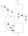
- Figure 6B shows the schematics of a method to determine a cost F(X) for a node X when the target tree includes multiple nodes according to one embodiment.
- expanding X 0 leads to a tree of nodes with subscript s
- expanding X f leads to a tree of nodes with subscript g.
- L g is selected 511 for growing, and specifically node X bestg is selected for expansion since it has the lowest cost among L g .
- Its expansion, with a control action A g results in a child node X g .
- ⁇ is a positive finite constant
- d ( X i , X j ) is a distance function between arbitrary two nodes X i and X j .
- X nears contains all nodes on which is within ⁇ distance from X g .
- X bests represents the node on the tree which gives the minimum estimated cost-to-go h ( X 0 , X g ) .
- kinematically/dynamically feasible paths 612 between X g and X bests are, with a higher probability, shorter (thus can be approximated better by l e ( X g , X bests )) than kinematically/dynamically feasible paths 611 between X 0 and X g , and thus a kinematically/dynamically feasible path between X bests and X g is much less likely to collide obstacles, and offers much better estimate of the cost-to-go.
- Figure 6C shows schematics of examples illustrating benefits of different embodiments.
- the vehicle needs to move from an initial state 101 to a target state 102, within an environment including various obstacles 103.
- a method without prioritizing control actions leads to a dense and complex tree 621 that includes of 6339 nodes according to a simulation.
- An embodiment with deterministic node expansion based on prioritized motion primitives achieves the desired motion with a simpler tree 622 that has only 2465 nodes.
- An embodiment that uses a doubletree construction achieves the desired motion with an even more simpler tree 623 of only 1325 nodes.
- Figure 7A shows a schematic that illustrates primitive motions associated with a set of control actions and integration times according to some embodiments.
- the set of all control actions and the set of integration times are designed such that distances between all node candidates of a given expandable node are at least greater than a certain threshold ⁇ defining sparsity of the graph.
- the distance function between two nodes corresponding to states X i and X j are defined as a weighted p-norm of the vector X i - X j :
- the kinematic vehicle model is used to generate node candidates based on the primitive motions, where a primitive motion includes a control action A i : ( s i , v i ) and integration time t fi .
- a primitive motion includes a control action A i : ( s i , v i ) and integration time t fi .
- s i and v i is a steering angle of the vehicle steering wheel and a longitudinal velocity of the vehicle, respectively.
- the dynamic vehicle model can be used to generate node candidates based on the primitive motions, where a primitive motion includes a control action A i : ( a si , a vi ) and integration time t fi .
- a si and a vi is a steering velocity of the vehicle steering wheel and a longitudinal acceleration of the vehicle, respectively.
- Some embodiments perform a node expansion, in addition to a node selection, in a deterministic manner to reduce the need to explore the space around the node with all possible primitive motions.
- an embodiment selects a first collision free primitive motion that reduces the cost of the expandable node, i.e., without testing subsequent primitive motions.
- some embodiments order a set of primitive motions based on similarity of each of the primitive motions to a primitive motion defining an edge of the graph leading to the expandable node and tests the primitive motions in that order.
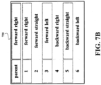
- Figure 7B shows an ordered list 720 of primitive motions used by some embodiments to expand a node.
- Some embodiments are based on understanding that there is no need to test all possible primitive motions, only one that is collision free and reduces the cost of the node we want to expand.
- one control action reduces the cost of a parent node, similar control action probably also would reduce the cost of the child node.
- a forward right primitive motion of a parent node is collision free, it make sense to start testing the motion primitives in an order governed by the similarity to the control action leading to the parent node.
- one embodiment tests the primitive motions starting with a primitive motion of an edge leading to the expandable node. Additionally, or alternatively, one embodiments, to increase space awareness of the graph, tests the primitive motions starting with primitive motions of a driving mode including a primitive motion of an edge leading to the expandable node.
- the driving mode can be a forward driving mode or a backward driving mode, in which the forward driving mode includes forward primitive motions defining a straight movement, a right turn movement, and a left turn movement in a forward direction, and the backward driving mode includes backward primitive motions defining a straight movement, a right turn movement, and a left turn movement in a backward direction. Additionally, or alternatively, the driving mode can be a straight driving mode or a turn driving mode, wherein the turn driving mode includes different primitive motions for turning movements of the vehicle with different curvatures.
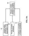
- Figure 8A shows a block diagram of a method for determining 541 a motion primitive or a subset of motion primitives to expand a selected node X best according to one embodiment.
- the embodiment selects 802 a motion primitive or a subset of motion primitives according to untried motion primitives, priority of untried motion primitives 803, and collision probability of untried motion primitives 804.
- the information 803 and 804 can be readily inferred from properties of the node 441c and 441d, as shown in Figure 4C
- Figure 8B shows a block diagram of a method for selecting a motion primitive during the expansion of the expandable node X best according to another embodiment.
- the embodiment selects 812 a motion primitive among untried motion primitives 801 such that the distance between the motion primitive and the motion primitive with the highest priority 441e is minimal.
- This rule is based on the realization that the motion primitive with highest priority 441e is more likely to produce a child node having the lowest cost. That is: the highest priority is assigned to the motion primitive, which gives the lowest node cost among all tried motion primitives. In case that no motion primitive has been tried, motion primitive with the highest priority 441e of X best is inherited from its parent node.
- a node is the root node of a tree, the collision probability of all motion primitives are zero (meaning all motion primitives are assumed to be collision free), and the priority of motion primitives 441d are initialized to 1 (means all motion primitives have the same priority).
- the priority and collision probability are initially inherited from its parent node.
- FIG. 9 shows a schematic of a system according to one embodiment.
- the system includes a vehicle 901 including a processor 902 configured for performing an automated parking 950.
- the vehicle also includes at least one sensor, such as a LIDAR 910 and/or a camera 920.
- the LIDAR sensor 910 is the low-resolution first sensor and the camera 920 is the high-resolution second sensor.
- the sensor 910 and/or 920 is operatively connected to the processor 902 and is configured for sensing information indicative of the geometry of at least part of the parking space. Using this information, the processor 902 determines and/or updates the map of the parking space 130. To that end, the processor 902 performs the automated parking 950 using the map 130.
- Figure 10 shows a block diagram of an automated parking system 1000 according to some embodiments.
- the system 1000 can be implemented internal to the vehicle 901. Additionally, or alternatively, the system 1000 can be communicatively connected to the vehicle 901.
- the senor 1010 can include color or grayscale cameras, which provide "color information.”
- color information refers to color and/or grayscale information.
- a color image or color information can be viewed as comprising 1 to N channels, where N is some integer dependent on the color space being used to store the image.
- N is some integer dependent on the color space being used to store the image.
- an RGB image comprises three channels, with one channel each for Red, Blue and Green information.
- the senor 1010 can include a depth sensor for providing "depth information.”
- the depth information can be acquired in a variety of ways using depth sensors.
- depth sensor is used to refer to functional units that may be used to obtain depth information independently and/or in conjunction with some other cameras.
- the depth sensor and the optical camera can be part of the sensor 1010.
- the sensor 1010 includes RGBD cameras, which may capture per-pixel depth (D) information when the depth sensor is enabled, in addition to color (RGB) images.
- the senor 1010 includes stereoscopic cameras.
- a depth sensor may form part of a passive stereo vision sensor, which may use two or more cameras to obtain depth information for a scene.
- the pixel coordinates of points common to both cameras in a captured scene may be used along with camera pose information and/or triangulation techniques to obtain per-pixel depth information.
- the processor 450 can be implemented using a combination of hardware, firmware, and software.
- the processor 450 can represent one or more circuits configurable to perform at least a portion of a computing procedure or process related to sensor fusion and/or methods for further processing the fused measurements.
- the processor 450 retrieves instructions and/or data from memory 1060.
- the memory 1060 can be implemented within the processor 450 and/or external to the processor 450.
- the term "memory” refers to any type of long term, short term, volatile, nonvolatile, or other memory and is not to be limited to any particular type of memory or number of memories, or type of physical media upon which memory is stored.
- the memory 1060 holds program codes that facilitate the automated parking.
- the memory 1060 can store the measurements of the sensors, such as still images, depth information, video frames, program results, as well as data provided by the IMU 1030 and other sensors.
- the memory 1060 can store a memory storing a geometry of the vehicle, a map of the parking space, a kinematic model of the vehicle, and a dynamic model of the vehicle.
- the memory 1060 can represent any data storage mechanism.
- the memory 1060 can include, for example, a primary memory and/or a secondary memory.
- the primary memory can include, for example, a random access memory, read only memory, etc. While illustrated in Figure 104 as being separate from the processors 450, it should be understood that all or part of a primary memory can be provided within or otherwise co-located and/or coupled to the processors 450.
- the above-described embodiments of the present invention can be implemented in any of numerous ways.
- the embodiments may be implemented using hardware, software or a combination thereof.
- the software code can be executed on any suitable processor or collection of processors, whether provided in a single computer or distributed among multiple computers.
- processors may be implemented as integrated circuits, with one or more processors in an integrated circuit component.
- a processor may be implemented using circuitry in any suitable format.
- embodiments of the invention may be embodied as a method, of which an example has been provided.
- the acts performed as part of the method may be ordered in any suitable way. Accordingly, embodiments may be constructed in which acts are performed in an order different than illustrated, which may include performing some acts simultaneously, even though shown as sequential acts in illustrative embodiments.
Landscapes
- Engineering & Computer Science (AREA)
- Business, Economics & Management (AREA)
- Automation & Control Theory (AREA)
- Mechanical Engineering (AREA)
- Transportation (AREA)
- Physics & Mathematics (AREA)
- Human Resources & Organizations (AREA)
- General Physics & Mathematics (AREA)
- Aviation & Aerospace Engineering (AREA)
- Strategic Management (AREA)
- Remote Sensing (AREA)
- Radar, Positioning & Navigation (AREA)
- Economics (AREA)
- Game Theory and Decision Science (AREA)
- Entrepreneurship & Innovation (AREA)
- Quality & Reliability (AREA)
- Medical Informatics (AREA)
- Evolutionary Computation (AREA)
- Operations Research (AREA)
- General Business, Economics & Management (AREA)
- Marketing (AREA)
- Development Economics (AREA)
- Tourism & Hospitality (AREA)
- Theoretical Computer Science (AREA)
- Health & Medical Sciences (AREA)
- Artificial Intelligence (AREA)
- Combustion & Propulsion (AREA)
- Chemical & Material Sciences (AREA)
- Traffic Control Systems (AREA)
- Control Of Position, Course, Altitude, Or Attitude Of Moving Bodies (AREA)
- Control Of Driving Devices And Active Controlling Of Vehicle (AREA)
Description
- This invention relates generally to path planning for vehicles, and more particularly to a path planning method for controlling a movement of a vehicle from an initial state into a target space in a deterministic manner.
- Document LONG HAN ET AL, "Unified path planner for parking an autonomous vehicle based on RRT", ROBOTICS AND AUTOMATION (ICRA), 2011 IEEE INTERNATIONAL CONFERENCE ON, IEEE, (20110509), doi:10.1109/ICRA.2011.5980105, ISBN 978-1-61284-386-5, pages 5622 - 5627, XP032033928 discloses a Rapidly-exploring Random Tree (RRT) based path planner.
- Document CSORVASI GABOR ET AL, "RTR+C*CS: An effective geometric planner for car-like robots", PROCEEDINGS OF THE 2015 16TH INTERNATIONAL CARPATHIAN CONTROL CONFERENCE (ICCC), IEEE, (20150527), doi:10.1109/CARPATHIANCC.2015.7145051, pages 85 - 90, XP033166594 discloses a global geometric path planning method for car-like robots.
- Document SARTINI T ET AL, "A resolution-adaptive strategy for probabilistic motion planning", WORLD AUTOMATION CONGRESS, 2002. PROCEEDINGS OF THE 5TH BIANNUAL JUNE 9-13, 2002, PISCATAWAY, NJ, USA, IEEE, (20020609), vol. 14, ISBN 978-1-889335-18-6, pages 591 - 596, XP010616555 discloses a resolution-adaptive strategy aimed at increasing the efficiency of probabilistic path planning.
- Several control systems employed by vehicles, either autonomous vehicles or vehicles executing in autonomous-driving mode, predict future, safe motions, or paths, of the vehicle, both in order to avoid obstacles, such as other vehicles or pedestrians, but also to optimize some criteria associated to the operation of the vehicle. The target state can either be a fixed location, a moving location, a velocity vector, a region, or a combination thereof. The surroundings, such as road edges, pedestrians, and other vehicles, are sensed by the sensors of the vehicle and/or are at least partially known by a priori given information.
- Path planning arises in a variety of applications such as autonomous vehicles, robotics, manufacturing, and computer vision applications. Many planning algorithms have been proposed, including, to name a few, graph-based A* and D* methods, continuous approaches involving navigation function and potential fields; more recently, sampling-based method such as probabilistic roadmaps (PRM), expansive-space trees, rapidly-exploring random trees (RRT), optimal variants RRT* and PRM*, and anytime RRT.
- One of the tasks for controlling the autonomous or semi-autonomous vehicles executing in autonomous-driving mode automatically parks a vehicle into a parked position and orientation referred herein as a target state. The parking task can be formulated as the following. Given vehicle dynamics, a map of the parking space, an initial state representing the vehicle's start position and orientation, and a target state representing the vehicle's target parked position and orientation, determine a desired path or motion of the vehicle from the initial state to the target state and then control the actuators of the vehicle, e.g., vehicle's gas pedal and steering wheel, to ensure that the vehicle follows the desired path or motion. However, due to nonholonomic constraints on the motion of the vehicle and a typically narrow free space in the parking space, such as a parking garage or a parking lot, path planning for automatically parking a vehicle is challenging.
- A broad spectrum of graph-based approaches search a pre-defined graph, which approximates the configuration space of a robot. The graph is somewhat static in the sense that each node and edge represent the same configuration and connecting path, respectively. Both nodes and edges of the graph are marked as collision-free or occupied during the exploration of search algorithms. Well-established algorithms such as A* and D* achieve resolution-completeness, with optimality guarantee under certain circumstances. Since the complexity of the pre-defined graph grows exponentially along with the dimension of the configuration space, these approaches become practically infeasible for high dimensional systems.
- Sampling-based methods may overcome the dimensionality problem, and gain prevalence on high dimensional systems. According to sampling-based methods, instead of using a pre-defined graph, a graph is constructed on-the-fly, where its nodes are randomly drawn from the configuration space. The effectiveness of these methods pivots on efficiency of the graph construction (or equivalently space exploration).
- However, the sampling-based methods, such as RRT methods, are computationally expensive. To that end, a number of work exploits biased sampling schemes to improve computation efficiency. For instance,
U.S. biases the sampling by a set of waypoints, where represent intermediate but milestone configurations. However, even biased sampling can be computationally impractical for some applications.Application 15/402353 - It is an object of some embodiments to disclose a motion planning method that allows real-time path generation for automated vehicle control. It is another object of some embodiments to disclose a motion planning method that allows real-time automated vehicle control, e.g., suitable for automated parking system and method. It is another object of some embodiments to provide such a method that reduce the computational cost of the path planning caused by probabilistic nature of sampling methods exploring the state space of a vehicle. It is another object of some embodiments to provide system and method for deterministic exploration of the state space of the vehicle with reduce computational complexity and/or memory requirements.
- The invention is defined by the independent claims. Preferable embodiments are defined by the dependent claims.
- The present invention is based on recognition that an automated vehicle control system for controlling a movement of a vehicle from an initial state of the vehicle and a target state of the vehicle can include a motion planner configured to construct a graph having multiple nodes defining states of the vehicle. A motion planner can use such a graph to explore the state space of the vehicle and to select control actions for moving a vehicle. For example, the nodes of the graph include an initial node defining the initial state of the vehicle and a target node defining the target state of the vehicle. Each pair of nodes in the graph is connected with an edge defined by one of collision free primitive motions moving the vehicle between the states of the connected nodes. A primitive motion is formed by a combination of a control action and an integration time defining the type and the extend of the primitive motion.
- Having this graph, the motion planner can determine a path through the graph connecting the initial node with the target node, such that the path defines a sequence of primitive motions moving the vehicle from the initial state to the target state to control the movement of the vehicle using the sequence of primitive motions. However, the challenge for such a system is in constructing the graph in a computationally efficient manner suitable for real-time path generation and control.
- Some implementations are based on understanding that sampling-based path planning methods can be used to find a desired path through a state space having an arbitrarily layout. However, an application of sampling-based path planning methods such as a rapid-exploring random tree (RRT) method and its variants, to the automated control problem can result in a number of wasted computations making this task computationally impractical for real time applications. For example, due to a number of obstacles that can separate a target state from the initial, e.g., current, state of a vehicle, the path to the target state can have different forms and shapes. To that end, in order to find such a path the entire state space may need to be sampled and tested for the path feasibility.
- As a result, probabilistic sampling-based path planning methods can unnecessarily sample all unexplored state space resulting in an impractical solution for real-time vehicle control applications. In addition, due to that unnecessary sampling, it is likely that the probabilistic planner outputs a path that is inconsistent with human's intuition. Such a path can be uncomfortable and confusing for a human driver. To that end, additionally or alternatively to an object of computational efficiency, it is an object of some implementations to generate paths resembling paths that a human operator may select.
- Some implementations are based on several realizations gleaned from observations on behavior and/or rationale of human operators for selecting a path for driving vehicle through a space having obstacles. These observations collectively or individually lead to some implementations of automatic path planning and control.
- First, one implementation is based on recognition that exploration of the space should be deterministic, i.e., not probabilistic, as how it would be performed by a human operator. Some implementations incorporate this realization into a planning and control system by constructing a graph connecting an initial state of the vehicle and the target vehicle in a deterministic manner. For example, one implementation constructs the graph (or tree) by iteratively selecting a node and expanding the selected node with a finite set of pre-defined primitive motions. The challenge of this method is in determining of how to deterministically identify the node to expand and/or how to deterministically select a motion primitive for expending the node to ensure computational efficiency of the method.
- Second, one implementation is based on recognition that a human operator performs the space exploration using not only local, but also global information. For example, a human operator would evaluate a space around the current, i.e., the initial, state of the vehicle and the space around the target state of the vehicle to make a decision about path of the vehicle. Some implementations are based on realization that the global information can be incorporated into the deterministic graph-based path planning method by constructing two trees forming the graph instead of one tree, i.e., by constructing an initial tree of nodes originating at the initial node corresponding to the initial state of the vehicle and by constructing a target tree of nodes originating at the target node corresponding to the target state of the vehicle. The initial tree represents local information around vehicle, the target tree represents local information around the target of the vehicle, and the relationships between the initial tree and the target tree provide insights on global information.
- In addition, this implementation is based on intuition confirmed by a number of simulations and experiments, that the obstacles surrounding a space can be more efficiently avoided by constructing an "outward tree" from the occluded space to a free space, rather than by constructing an "inward tree" from the free space toward the occluded space. In a number of applications, such as autonomous parking systems, the parking space is typically more occluded than the space in a garage or a parking lot leading toward the parking space. To that end, some implementations are based on realization that doubletree space exploration can be more computationally efficient than a singletree space exploration and can better adhere to a human intuition.
- The invention takes advantage of computational efficiency of doubletree space exploration by selecting the node on the initial or target tree to expand. Specifically, the invention selects an expandable node in the initial tree or the target tree based on a cost of the expandable node, and expend the graph by adding a child node connected to the expandable node with an edge defined by a collision free primitive motion, such that a cost of the child node is less than the cost of the expandable node. In such a manner, deterministic selection and expansion of the trees are achieved.
- In addition, as used herein, a cost of a node is a minimum cost for reaching the target node from the initial node through the node and includes a first cost of a first path through nodes of the initial tree (to consider local information around the initial state), a second cost of a second path through nodes of the target tree (to consider local information around the target state), and a third cost of a third path between nodes of the initial tree and the target tree (to consider relationship between initial and target states). Such a selection of expandable nodes allows considering information gleaned from the construction of both trees making the graph extension more computationally efficient. For example, a number of experiments demonstrated that doubletree graph construction determines the graph with less nodes than a singletree graph construction.
- Third, one implementation is based on realization than a node expansion, in addition to a node selection, can also be performed in a deterministic manner to reduce the need to explore the space around the node with all possible primitive motions. To that end, the invention selects a first collision free primitive motion that reduces the cost of the expandable node, i.e., without testing subsequent primitive motions. To further reduce the computational burden, the invention orders a set of primitive motions based on similarity of each of the primitive motions to a primitive motion defining an edge of the graph leading to the expandable node and tests the primitive motions in that order. This encourages smoothness of vehicle movement, as human operator would want, and, in practice, helps to reduce the complexity of the constructed graph. The reduction of node expansions reduces the sparsity of the constructed graph that on one hand improve computation efficiency, while on another hand reduces options for space exploration. To address this problem created by deterministic node expansions of some implementations, some implementations vary the sparsity of the graph at different portions of the graph. For example, one implementation maintains a list of potentially expandable node in a memory of motion planner and selects a value of the sparsity based on a length of a list of expandable nodes. The value of the sparsity can be defined by one or combination of an integration time of control actions forming the primitive motions, and a minimum allowed distance between the child node of the expandable nodes to a nearest node in the graph.
- Accordingly, this invention is directed to a system for controlling a movement of a vehicle from an initial state of the vehicle and a target state of the vehicle. The system includes a motion planner including a processor configured to construct a graph having multiple nodes defining states of the vehicle, wherein the nodes include an initial node defining the initial state of the vehicle and a target node defining the target state of the vehicle, wherein each pair of nodes in the graph is connected with an edge defined by one of collision free primitive motions moving the vehicle between the states of the connected nodes, determine a path through the graph connecting the initial node with the target node, such that the path defines a sequence of primitive motions moving the vehicle from the initial state to the target state; and transmit the sequence of primitive motions to a controller of the vehicle configured to control the movement of the vehicle using the sequence of primitive motions.
- The motion planner is configured to determine the graph by constructing an initial tree of nodes originating at the initial node and by constructing a target tree of nodes originating at the target node, wherein, to construct the initial tree or the target tree, the motion planner is configured to select an expandable node in the initial tree or the target tree based on a cost of the expandable node, and expand the graph by adding a child node connected to the expandable node with an edge defined by a collision free primitive motion, such that a cost of the child node is less than the cost of the expandable node, wherein the cost of a node is a minimum cost for reaching the target node from the initial node through the node and includes a first cost of a first path through nodes of the initial tree, a second cost of a second path through nodes of the target tree, and a third cost of a third path between nodes of the initial tree and the target tree.
- Further, the motion planner, to expand the expandable node, is configured to order a set of primitive motions based on similarity of each of the primitive motion in the set to a primitive motion defining an edge of the graph leading to the expandable node, to produce an ordered set of primitive motions; select, from the ordered set of primitive motions, a first collision free primitive motion that reduces the cost of the expandable node; and expand the graph with the first collision free primitive motion.
- This invention is also directed to a method for controlling a movement of a vehicle from an initial state of the vehicle and a target state of the vehicle, wherein the method uses a processor coupled with stored instructions implementing the method, wherein the instructions, when executed by the processor carry out steps of the method that includes constructing a graph having multiple nodes defining states of the vehicle, wherein the nodes include an initial node defining the initial state of the vehicle and a target node defining the target state of the vehicle, wherein each pair of nodes in the graph is connected with an edge defined by one of collision free primitive motions moving the vehicle between the states of the connected nodes, wherein the graph includes an initial tree of nodes originating at the initial node and a target tree of nodes originating at the target node, wherein, to construct the initial tree or the target tree, the processor is configured to select an expandable node in the initial tree or the target tree based on a cost of the expandable node, and expand the graph by adding a child node connected to the expandable node with an edge defined by a collision free primitive motion, such that a cost of the child node is less than the cost of the expandable node, wherein the cost of a node is a minimum cost for reaching the target node from the initial node through the node and includes a first cost of a first path through nodes of the initial tree, a second cost of a second path through nodes of the target tree, and a third cost of a third path between nodes of the initial tree and the target tree; determining a path through the graph connecting the initial node with the target node, such that the path defines a sequence of primitive motions moving the vehicle from the initial state to the target state; and transmitting the sequence of primitive motions to a controller of the vehicle configured to control the movement of the vehicle using the sequence of primitive motions.
- Further, to expand the expandable node, the method further comprises ordering a set of primitive motions based on similarity of each of the primitive motion in the set to a primitive motion defining an edge of the graph leading to the expandable node, to produce an ordered set of primitive motions; selecting, from the ordered set of primitive motions, a first collision free primitive motion that reduces the cost of the expandable node; and expanding the graph with the first collision free primitive motion.
- This invention is also directed to a non-transitory computer readable storage medium embodied thereon a program executable by a processor for performing a method that includes constructing a graph having multiple nodes defining states of the vehicle, wherein the nodes include an initial node defining the initial state of the vehicle and a target node defining the target state of the vehicle, wherein each pair of nodes in the graph is connected with an edge defined by one of collision free primitive motions moving the vehicle between the states of the connected nodes, wherein the graph includes an initial tree of nodes originating at the initial node and a target tree of nodes originating at the target node, wherein, to construct the initial tree or the target tree, the processor is configured to select an expandable node in the initial tree or the target tree based on a cost of the expandable node, and expand the graph by adding a child node connected to the expandable node with an edge defined by a collision free primitive motion, such that a cost of the child node is less than the cost of the expandable node, wherein the cost of a node is a minimum cost for reaching the target node from the initial node through the node and includes a first cost of a first path through nodes of the initial tree, a second cost of a second path through nodes of the target tree, and a third cost of a third path between nodes of the initial tree and the target tree; determining a path through the graph connecting the initial node with the target node, such that the path defines a sequence of primitive motions moving the vehicle from the initial state to the target state; and transmitting the sequence of primitive motions to a controller of the vehicle configured to control the movement of the vehicle using the sequence of primitive motions.
- Further, to expand the expandable node, the method further comprises ordering a set of primitive motions based on similarity of each of the primitive motion in the set to a primitive motion defining an edge of the graph leading to the expandable node, to produce an ordered set of primitive motions; selecting, from the ordered set of primitive motions, a first collision free primitive motion that reduces the cost of the expandable node; and expanding the graph with the first collision free primitive motion.
-
- [
Fig. 1A ]
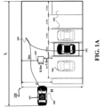
Figure 1A shows an example of a parking scenario addressed by some embodiments. - [
Fig. 1B ]
Figure 1B shows an exemplar schematic of geometrical representation of a vehicle according to some embodiments. - [
Fig. 1C ]
Figure 1C shows a map of a parking space corresponding to the parking scenario ofFigure 1A . - [
Fig. 2A ]
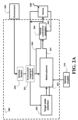
Figure 2A shows a block diagram of an automated vehicle control system according to one embodiment. - [
Fig. 2B ]
Figure 2B shows a block diagram of a general structure of the motion-planning system according to one embodiment. - [
Fig. 3A ]
Figure 3A shows a block diagram of a method performed by a motion planner according to some embodiments. - [
Fig. 3B ]
Figure 3B shows a schematic of determining the graph using doubletree construction according to one embodiment. - [
Fig. 3C ]
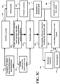
Figure 3C shows a block diagram of a method for a motion planning method according to some embodiments. - [
Fig. 4A ]
Figure 4A shows a block diagram of a graph construction method according to one embodiment. - [
Fig. 4B ]
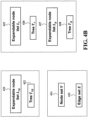
Figure 4B shows exemplars of data structures representing a graph according to some embodiments. - [
Fig. 4C ]
Figure 4C shows a data structure of a node according to one embodiment. - [
Fig. 5A ]
Figure 5A shows a flow chart of a method for tuning graph growth parameters according to principles of some embodiments. - [
Fig. 5B ]
Figure 5B shows a flow chart of a method for tuning graph growth parameters according to another embodiment. - [
Fig. 5C ]
Figure 5C shows a block diagram of a method for selecting an expandable node from the list of expandable nodes according to some embodiments. - [
Fig. 5D ]
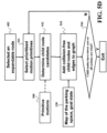
Figure 5D shows a block diagram of node expansion according to one embodiment. - [
Fig. 5E ]
Figure 5E shows a block diagram of several stop criteria used by some embodiments to terminate the iterative graph construction. - [
Fig. 6A ]
Figure 6A shows schematics of a method to determine a cost F(X) for a node X when the target tree includes only a target node according to one embodiment. - [
Fig. 6B ]
Figure 6B shows the schematics of a method to determine a cost F(X) for a node X when the target tree includes multiple nodes according to one embodiment. - [
Fig. 6C ]
Figure 6C shows schematics of examples illustrating benefits of different embodiments. - [
Fig. 7A ]
Figure 7A shows a schematic that illustrates primitive motions associated with a set of control actionsand integration times according to some embodiments.
- [
Fig. 7B ]
Figure 7B shows an ordered list of primitive motions used by some embodiments to expand a node. - [
Fig. 8A ]
Figure 8A shows a block diagram of a method for determining a motion primitive or a subset of motion primitives to expand a selected node according to one embodiment. - [
Fig. 8B ]
Figure 8B shows a block diagram of a method for selecting a motion primitive during the expansion of the expandable node according to another embodiment. - [
Fig. 9 ]
Figure 9 shows a schematic of a system according to one embodiment. - [
Fig. 10 ]
Figure 10 shows a block diagram of an automated parking system according to some embodiments. - It is an object of some embodiments to disclose a path and/or motion planning method that allows real-time path generation for automated vehicle control. It is another object of some embodiments to disclose a motion planning method that allows real-time automated vehicle control, e.g., suitable for automated parking system and method. For clarity purposes only, some embodiments are described in relation to automated parking scenario. However, principles explained in relation to parking scenarios are used by alternative embodiments in other automated vehicle control applications.
-
Figure 1A shows an example of a parking scenario addressed by some embodiments. In this example, the boundary of aparking space 150 is represented by a rectangle with a size of L × H. Thevehicle 100 has aninitial state 101 and needs to be parked at a parking spot defined by atarget state 102. Each state, e.g., the initial and the target state, define position and orientation of the vehicle. Theparking space 150 includes obstacles. The obstacles can be part of the layout of the parking space, i.e.,permanent obstacles 103, such as walls and/or columns of the parking space. Dimensions of the permanent obstacles are usually known, or can be estimated to a reasonable extent.Figure 1A depicts non-limiting examples of such dimensions. - Additionally, or alternatively, obstacles can include other parked or moving
vehicles 104. Geometrical dimensions of thevehicles 104 and thevehicle 100 to be parked can be determined based on the type of the vehicle. For clarity, this invention considers a front wheel drive vehicle; although different embodiments are applied to other vehicles including rear wheel drive and full wheel drive vehicles. - In some embodiments, layout of the parking space and position of the
obstacles 103 are specified on the map of the parking space. Such a map can be predetermined or constructed in real time during or before the parking task. Various embodiments determine akinematic path 105 connecting the initial state and the target state such that the kinematic path is feasible and collision free. -
Figure 1B shows an exemplar schematic of geometrical representation of a vehicle according to some embodiments. In this example, the vehicle is abstracted as arectangle 115. The vehicle state includes the position (x, y) 110, which represents the midpoint of its rear wheel axis, and theorientation θ 120, which denotes the angle between the vehicle body axis and the horizontal axis. - Path planning is to solve the following problem. Given an initial configuration X 0 ∈, a goal configuration Xf ∈
 , and system (2), find a collision free kinematically feasible path
 which
which
- starts at X 0 and ends at Xf ;
- lies in the collision-free configuration space ;

- satisfies the system kinematics (2).
- Let J(·) be a cost function that assigns to each non-trivial path a non-negative cost. Optimal path planning is to find a collision free kinematically feasible path

- Motion planning of different embodiments determine how the vehicle moves along the path using kinematic and/or dynamic model of the
vehicle 100. For example, a dynamic model of a vehicle accounts for time-dependent changes in the state of the vehicle. Dynamic models typically are represented by differential equations. In one embodiment, the dynamic model of the vehicle is fifth order differential equations
- In some embodiments, a path is generated according to the dynamic model (1). A dynamically feasible path is a solution of the dynamic model (1). Accordingly, a vehicle state is X = (x, y, θ, v, ζ). Since a vehicle typically starts and ends with zero velocity and steering angle, thus the initial and target state for the dynamic model (1) is X 0 = (x 0 , y 0 , θ 0 , 0,0) and Xf = (xf, yf, θf, 0,0), respectively.
- Additionally, or alternatively, some embodiments use a kinematic model of the vehicle for the motion planning that describes motion of the vehicle without consideration of mass of the vehicle or forces that caused the motion. In one embodiment, the following kinematic model is considered

- According to this embodiment, a path is kinematically feasible if it is a solution of the kinematic model (2). A vehicle state X = (x, y, θ) is collision free only if the vehicle located at X does not collide with any obstacle, and lies completely inside the
boundary 105. All collision free vehicle states constitute a collision free configuration space. Theinitial state 101 is abbreviated as X 0 = (x 0 , y 0 , θ 0), and thetarget state 102 is denoted by Xf = (xf, yf, θf ). For a specific parking task with a parking space represented by a rectangle L × H, the vehicle state always belongs to a state space: [0, L) × [0, H) × [0,2π).
- In such a manner, different embodiments can be applied to both the kinematic model and the dynamic model. Without loss of generality, the following description is developed on the basis of the kinematic model.
- A treeis a union of a node set
 ⊂
⊂ and an edge set, i.e.,
 = (,). Without causing confusion, node, configuration, and vehicle state are used interchangeably below. An edge E(Xi,Xj ) ∈represents a collision free kinematically feasible path between nodes Xi and Xj. For a finite set, || denotes the number of its elements.
 - Some embodiments determine whether a vehicle state is without collision based on a geometric representation of the parking space, which is also referred to as a map of the parking space. The map of the parking space is derived by approximating all obstacles and the boundary of the parking space as simple geometric shapes. In one embodiment,
obstacles 103 in the environment (equivalently the parking space) can be approximated as rectangles, which are derived by constructing a minimal bounding box for each obstacle. With geometric approximation of obstacles and boundary of the parking space, the parking space or the environment can be fully described by a list of geometric objects. -
Figure 1C shows amap 130 of a parking space corresponding to the parking scenario ofFigure 1A . Both types of obstacles are merged together as one type ofpermanent obstacles 103 using a rectangular representation. An obstacle can be approximated by multiple geometric shapes, depending on computing power of an onboard processor for path planning. For instance, in another embodiment, obstacles can be approximated by constructing a bounding circle for each obstacle if the computing power is not sufficient. Alternatively, an obstacle can be approximated by a polytope, which however may increase computation burden in path planning. Also, obstacles in the parking space might not be approximated by the same geometric shape. In some embodiments, the environmental map is decomposed into a group of cells, each of which corresponds to a configuration and its neighborhood with a certain volume. Cells could have different volumes. Obstacles in the parking space can be represented by a group of cells. -
Figure 2A shows a block diagram of automatedvehicle control system 299 according to one embodiment. Environment mapping andlocalization block 201 constructs or updates the map of the space, e.g., parking space, and determines the current location of the vehicle by sensing the environment and vehicle operation condition. For example, an inertial measurement unit (IMU), which may include 3-axis accelerometer(s), 3-axis gyroscope(s), and/or magnetometer(s), can be used to sense the vehicle operation. A global positioning system sensor can be used to provide position and velocity of the vehicle. Sensors to sense theenvironment 200 can be video cameras capturing obstacles including other vehicles, pedestrians, and buildings, ultrasonic/radar and LiDAR sensors detecting distance between the vehicle and obstacles, etc. In one embodiment, the environment map is further processed to generate a geometric representation of the parking space as shown inFigure 1C . -
Target state selection 202 selects a target state for a parking spot to park the vehicle by identifying parking lot candidates, and submits the target state to amotion planning block 203. In one embodiment, the available parking spots are tracked by a separate system associated with the management of the parking garage. Additionally, or alternatively, the parking spots can be detected using thesensors 230 of the automated system. In one embodiment, themotion planning block 203 checks to determine whether the target state is parkable, i.e., there is a feasible path to the parking spot, or not, and notifies the targetstate selection block 202 the check result. If the target state is not parkable, thetarget selection block 202 selects another target state for evaluation. In another embodiment, the targetstate selection block 202 can also evaluate whether the target state is parkable, and only sends a parkable target state to the motion planning block. - If the target state is parkable, then the
motion planning 203 initiates a complete motion planning procedure to determine areference trajectory 241 based on one or combination of thevehicle models 210, the initial and target states of the vehicle, and the map of the parking space. The reference trajectory is a sequence of primitive motions of the vehicle. For example, in one embodiment, the reference trajectory defines profiles of the vehicle velocity and steer angle over time. In another embodiment, the reference trajectory defines the profile of the vehicle state (x, y, θ) over time. In most of cases, the reference trajectories various forms are equivalent and one trajectory defines another via the vehicle model. - The motion-planner transmits the reference trajectory determined by the sequence of primitive motions to
controller 204 of the vehicle. Given thereference trajectory 241, vehicle controllers andactuators 204 determine and exert control commands to enforce the vehicle state track itsreference trajectory 241. In one embodiment, the control commands could be gas pedal pressure and/or steering torque. The vehicle controller/actuators may use signal 243 and 244 to determine control commands. Thesignal 243 can be a measured steering angle, or measured currents of motors moving the steering wheel or the gas pedal, the output of the IMU, and the current state of the vehicle estimated by thelocalization block 201. -
Figure 2B shows a block diagram of a general structure of the motion-planningsystem 203 according to one embodiment. The motion-planningsystem 203 includes at least oneprocessor 270 for executing modules of the motion-planningsystem 203. Theprocessor 270 is connected 271 to amemory 280 that storesgeometrical information 281 such as geometry of the vehicle and a map of the parking space. Thememory 280 can also store the models of thevehicle 282 such as a kinematic model of the vehicle and/or a dynamic model of the vehicle. Thememory 280 can also store theinternal information 283 of the motion planner, including, but not limited to, an initial state of the vehicle, a target state of parked vehicle, cost function, values of each computed state, the motion leading up to each state, a geometric graph, a kinematic graph, waypoints, reference trajectory. In some embodiments, thememory 280 can include stored instructions implementing the method for the automated vehicle control, wherein the instructions, when executed by theprocessor 270 carry out at least some steps of the method. -
Figure 3A shows a block diagram of a method performed by amotion planner 203 of asystem 299 for controlling a movement of a vehicle from an initial state of the vehicle and a target state of the vehicle according to some embodiments. The motion planner is configured to construct 310 a graph having multiple nodes defining states of the vehicle. The nodes include an initial node defining the initial state of the vehicle and a target node defining the target state of the vehicle. Each pair of nodes in the graph is connected with an edge defined by one of collision free primitive motions moving the vehicle between the states of the connected nodes. - The motion planner also configured to determine 330 a path through the graph connecting the initial node with the target node, such that the path defines a sequence of primitive motions moving the vehicle from the initial state to the target state; and to transmit 335 the sequence of primitive motions to a controller of the vehicle configured to control the movement of the vehicle using the sequence of primitive motions. Having the graph, the path can be determined using various optimization techniques optimizing a parameter of the path, such as one or combination of its cost and smoothness.
- In some embodiments, the motion planner constructs 310 the graph using doubletree construction. Specifically, motion planner determines the graph by constructing an initial tree of nodes originating at the initial node and by constructing a target tree of nodes originating at the target node. To construct the initial tree or the target tree, the motion planner is configured to select 315 an expandable node in the initial tree or the target tree based on a cost of the expandable node, and expend 320 the graph by adding a child node connected to the expandable node with an edge defined by a collision free primitive motion, such that a cost of the child node is less than the cost of the expandable node.
- As used herein, the cost of a node is a minimum cost for reaching the target node from the initial node through the node and includes a first cost of a first path through nodes of the initial tree, a second cost of a second path through nodes of the target tree, and a third cost of a third path between nodes of the initial tree and the target tree. In various embodiments, the cost of the node is indicative of one or combination of a travel time of the vehicle from the initial state to the target state through the state of the node, a distance the vehicle travels from the initial state to the target state through the state of the node, a rate of change of a mode of movement of the vehicle traveling from the initial state to the target state through the state of the node.
- Some embodiments are based on intuition confirmed by a number of simulations and experiments, that the obstacles surrounding a space can be more efficiently avoided by constructing an "outward tree" from the occluded space to a free space, rather than by constructing an "inward tree" from the free space toward the occluded space. In a number of applications, such as applications of autonomous parking systems, the parking space is typically more occluded than the space in a garage or a parking lot leading toward the parking space. To that end, some embodiments are based on realization that double tree space exploration can be more computationally efficient than a single tree space exploration and better adhere to a human intuition.
- Some embodiments take advantage of computational efficiency of double trees space exploration by selecting the node on the initial or target tree to expand. Specifically, some embodiments select an expandable node in the initial tree or the target tree based on a cost of the expandable node, and expend the graph by adding a child node connected to the expandable node with an edge defined by a collision free primitive motion, such that a cost of the child node is less than the cost of the expandable node.
-
Figure 3B shows a schematic of determining the graph using doubletree construction according to one embodiment. In this example, the graph is constructed from both ends using aninitial tree 321, having aninitial node 311 corresponding to theinitial state 101, and atarget tree 322, having atarget node 312 corresponding to thetarget state 102. The initial tree has a node set and an edge set. The target tree also has a node set and an edge set. - During a current iteration, a
node 313 from the initial or the target tree is selected based on its cost. In this example, thenode 313 is selected from the initial tree. For example, in one implementation, the nodes from the initial or the target tree are selected interchangeably. Thenode 313 has the minimum cost for reaching the target node from the initial node through thenode 313 among all nodes of the initial tree. This node is aimed to be expanded with a child node, and, thus, this node is referred as an expandable node. - The
node 313 is selected as an expandable node only if there is a collision free motion primitive that can expand the initial tree by adding a child node connected to the expandable node with an edge defined by that collision free primitive motion. Otherwise, thenode 313 is not expandable. To that end, in some embodiments, the motion planner, for selecting the expandable node, is configured to test multiple nodes in an order of their respective costs and to select the first of the tested nodes with the collision free primitive motion reducing the cost of the selected node as the expandable node. - For example, if all primitive motions that can reduce the cost of the
node 313 lead to theobstacles 103, then thenode 313 is not expandable, and the embodiments select another node, e.g., anode 331 with cost greater than the cost of thenode 313 to expand. If thenode 331 is expandable, i.e., there is a collision free motion primitive, such as 336 that reduces the cost of theexpandable node 331, the embodiment uses theedge 336 defined by this collision free motion primitive to add to the initial tree 321 achild node 337 that have a cost less than the cost of thenode 331. - Next, in some implementations, the embodiment expands the target tree, e.g., from the node 341. For example, some embodiments construct initial and target trees alternatively, i.e. one after another. The graph construction continues until a termination condition is reached. For example, in one embodiment, the motion planner stops constructing the graph when the initial tree and the target tree are connected with a collision free Reed-Shepp's path.
- In such a manner, deterministic selection and expansion of the trees are achieved. In addition, as used herein, cost of a node is a minimum cost for reaching the target node from the initial node through the node and includes a first cost of a first path through nodes of the initial tree (to consider local information around the initial state), a second cost of a second path through nodes of the target tree (to consider local information around the target state), and a third cost of a third path between nodes of the initial tree and the target tree (to consider relationship between initial and target states). Such a selection of expandable nodes allows considering information gleaned from the construction of both trees making the graph extension more computationally efficient. For example, a number of experiments demonstrated that doubletree graph construction determines the graph with less nodes than a singletree graph construction.
- Some embodiments are based on additional realization than a node expansion, in addition to a node selection, can also be performed in a deterministic manner to reduce the need to explore the space around the node with all possible primitive motions. To that end, one embodiment selects a first collision free primitive motion that reduces the cost of the expandable node. To further reduce the computational burden, some embodiments order a set of primitive motions based on similarity of each of the primitive motions to a primitive motion defining an edge of the graph leading to the expandable node and tests the primitive motions in that order. These embodiments encourage smoothness of vehicle movement, as human operator would want, and, in practice, help to reduce the complexity of the constructed graph, because if a motion primitive leading to a node is collision free, it is possible and even likely that the same motion primitive originating at the node is also collision free.
- For example, the
edge 336 is created by the same primitive motion defining an edge of the graph leading to theexpandable node 331. Even if there are other primitive motions that can even further reduce the cost of thenode 331, the first tested primitive motion is selected to expand the node. -
Figure 3C shows a block diagram of a method for a motion planning method according to some embodiments. Beginning with the geometry of vehicle, the map of the parking space, and initial and target states, the method first initializes 345 a graphand outputs an
initial graph 350. Based on the initial graph andprimitive motions 355, the graph is constructed 360 by repeating two steps: node selection and node expansion using prioritized control actions. As a result, agraph 365 connecting the initial state and the target state or growing into an attraction region of the target state is obtained, and used to determine 370 a kinematic ordynamic path 375. A graph is said growing into an attraction region of the target state if it includes a node which is within ε distance from the target node. The path can include a sequence of primitive motions driving the vehicle from the initial state to the target state. In some embodiments, a reference trajectory is determined 385 on the basis of a kinematic path and the dynamic model of thevehicle 380. In another embodiment a reference trajectory is determined by smoothing thedynamic path 375 based on thedynamic model 380.Reference trajectory 390 is fed into a control module to control 395 the motion of the vehicle such that the vehicle motion follows the reference trajectory, based on sensedsignal 391 such as vehicle's current state. -
Figure 4A shows a block diagram of a graph construction method according to one embodiment. The graph is initialized 345 based on the initial and/or target states, pre-set graph growth parameters are first adjusted 401 according to a combination of several metrics. For example, the growth parameters can include one or combination of a set of motion primitives, sparsity of the graph, order of selecting motion primitive for node expansion. The growth parameters allows to construct the graph with non-uniformly distributed nodes having different values of sparsity at different portions of the graph. In some embodiments, the motion planner selects a value of the sparsity based on a length of a list of expandable nodes. The value of the sparsity is defined by one or combination of an integration time of control actions forming the primitive motions, and a minimum allowed distance between the child node to a nearest node in the graph. - In some embodiments, the motion planner stores in a memory one or more lists of expandable nodes. If all expandable node lists are empty, the graph construction stops to select different grows parameters or the method returns failure. Otherwise, an
expandable node 441 is selected 402 from an expandable node list. Theexpandable node 441 is further expanded 403, where prioritized control actions are applied to fulfill the node expansion. Based on the map of the parking space, thenode expansion 403 determines possibly none, one, or a set of collision-free child nodes of the expandable node, and accordingly none, one, or a set of collision-free edges between the expandable node and its child nodes. These collision-free child nodes and edges are added to the graph. The construction algorithm terminates if the newly constructed graph meets certain stop criteria; otherwise, repeatstuning 401,selection 402, andexpansion 403. -
Figure 4B shows exemplars of data structures representing a graph according to some embodiments. For example, in one embodiment, a graphincludes at least aset 431 of nodes, and aset 432 of edges, where a node is created based on a certain collision-free state of the vehicle X. An edge represents a collision free kinematically/dynamically feasible path between two nodes. In one embodiment, the graph includes at least alist 421 of expandable node
tree 422. The
graph initialization 345 creates an initial node based on the initial state, and adds the initial node to the expandable list
- In one embodiment, the attraction region of a state is its neighborhood which includes all possible states within a certain distance from the state. A primitive motion is represented by a pair of a pre-defined control action Ai and its integration time tfi , or a sequence of states results from applying the pair (Ai, tfi ) to the vehicle model. In some embodiments, control actions such accelerations are applied to the vehicle dynamic model to obtain states. In another embodiment, control actions such as velocity and steering angle are applied to the vehicle kinematic model to produce the corresponding states.
- In some embodiments, a pre-defined control action for the vehicle is a composition of steering angle and longitudinal velocity. For simplicity, let us normalize the steering angle and the longitudinal velocity so that both take values within [-1,1]. Therefore a control action of the vehicle will be defined over a domain [-1,1]×[-1,1]. In order to apply methods taught in this invention, the domain needs approximated to produce pre-defined control actions. In one embodiment, an approximation of the domain is obtained by discretizing the range of the steering angle [-1,1] into several (e.g. 5) possible actions {-1,-0.5,0.,0.5,+1}; whereas the range of the longitudinal velocity is discretized into several (e.g. 2) possible actions {-1,+1}. The discretization induces a pre-defined action set including pre-defined control actions. For example, in one embodiment, the pre-defined action set A includes ten elements: {(-1,1),(-0.5,1),(0,1),(+0.5,1),(1,1), (-1,-1),(-0.5,-1),(0,-1),(+0.5,-1),(1,-1)}. The pre-defined control action Ai can be any element of A.
- Similarly, the integration time is a finite positive real number. In one embodiment, the integration time is also normalized such that its domain is [0,1]. For example, one embodiment discretizes its domain into several values. For instance, the domain is uniformly discretized into a finite set of five elements TF = {0.2,0.4,0.6,0.8,1}, and value of tfi is selected from the finite set TF.
- Given action set A and integration time set TF, a motion primitive is associated with a pair of (Ai,tfi). In some embodiments, a set of control actions is pre-defined as


- Accordingly, || primitive motions are defined, with the ith primitive motion corresponds to a pair (Ai, tfi ).

- In some embodiment, each action Ai could have the same integration time. That is TF only contains one element. Motion primitives can be defined accordingly.
- In another embodiment, the graph includes a
list 425 of expandable node
initial tree 426, and another expandable node
list 
target tree 428. The
graph initialization 345 creates a target node based on the target state, and adds the initial node and target node to the list

-
Figure 4C shows a data structure of a node according to one embodiment. Anode 441 has properties of astate 441a,node cost 441b, collision probability ofmotion primitives 441c, priority ofmotion primitives 441d, and motion primitive with thehighest priority 441e. For example, astate 441a describes the vehicle configuration or location; thecost 441b describes an estimated cost of a path which passes through the node and connects the initial and target states; collision probability of a motion primitive specifies the estimated likelihood that the motion primitive leads to collision;priority 441d determines which primitive mostly likely leads to reduction of cost. - In some embodiment, the collision probability takes a real value on a continuous domain between 0 and 1; and the priority probability takes a real value on a bounded continuous domain. In another embodiment, the collision probability takes a discrete value from a finite set containing two elements {0,1}|; and the priority takes a discrete value from a finite set containing two elements {0,1}.
- In some embodiments, a new child node initially inherits collision probability and priority of motion primitives from its parent, when the node is generated by applying a primitive to the parent. After the parent node is expanded by applying a motion primitive, the collision probability and the priority of the applied primitive is updated according to the outcome of the primitive. For example, if the primitive leads to the new node and a path between the new node and the parent node in collision, then the collision probability of the primitive of the parent node is increased. In an extreme case, the collision probability is set to one. If the primitive leads to the new node giving a lower cost than the parent node, the priority of the primitive of the parent node is increased, otherwise decreased. In some cases, the priority is increased to one or reduced to zero, depending on the cost of the new node. In such a manner, the deterministic approach that takes advantage of the probabilistic estimation of the motion primitives for each expandable node reduces the computational complexity of graph construction.
- In one embodiment, the priority of a motion primitive is increased or decreased by an amount, which is linearly proportional to the difference between costs of the parent node and the new node. This embodiment increases relative priority of other motion primitives with respect to parent motion primitive to better consider various options in deterministic graph expansion.
- Some embodiments are based on realization that
deterministic graph construction 360 leads to the reduction in the number of expandable nodes. In turn, reduction of node expansions increases the sparsity of the constructed graph that on one hand improve computation efficiency, while on another hand reduces options for space exploration. To address this problem created by deterministic node expansion, some embodiments vary sparsity of the graph at different portions of the graph. For example, one implementation maintains a list of potentially expandable node in a memory of motion planner and selects a value of the sparsity based on a length of a list of expandable nodes. For example, the value of the sparsity is defined by one or combination of an integration time of control actions forming the primitive motions, and a minimum allowed distance between the child node of the expandable nodes to a nearest node in the graph. -
Figure 5A shows a flow chart of a method for tuninggraph growth parameters 401 for a single treeof the
graph 365 according to principles of some embodiments. The value of the sparsity defining the neighbor of a vehicle state is adjusted 503 according to the length of theexpandable node list 502. In particular, if the length of the expandable node list
-
Figure 5B shows a flow chart of a method for tuninggraph growth parameter 402, for a doubletree graph,according to some embodiments. Some principles of these embodiments are similar to sparsity adjustment ofFigure 5A . Theblock 402 returns failure only if both expandable node lists
-
Figure 5C shows a block diagram of a method for selecting 402 an expandable node from the list of expandable nodes according to some embodiments. Normally, some embodiments select the node having the lowest estimated cost in the expandable node list. If the expandable node has been fully expanded (all control actions have been tried), the node is removed 523 from the list, and the algorithm ought to find the lowest cost node from the new expandable node list. -
Figure 5D shows a block diagram ofnode expansion 403 according to one embodiment. With the selected expandable node Xbest, a control action Ai or a subset of control actions
- In some embodiments, a primitive motion specifies a control action Ai and time period tfi applied to the vehicle model. A primitive motion is stored in memory either in the form of the pair (Ai, tfi ), or a sequence of states result from the corresponding control action and time period. The sequence of states are obtained by integrating the vehicle kinematic or dynamic model with a zero initial condition and the corresponding primitive motion.
- As shown in
Figure 5D , a child node candidate X and the edge (Xbest, X) are added to the node set and the edge set of the graph, respectively, only if the path as a result of the primitive motion between Xbest and X is collision free, using themap information 130. A node cost of the child node X is estimated as F(X), and checked 544 whether it is lower than the node cost of Xbest. If yes, the node expansion exits; otherwise, which is the case Xbest still has the lowest node cost, another control action or a subset of control actions is selected to continue the expansion of the node Xbest. -
Figure 5E shows a block diagram of several stop criteria used 404 by some embodiments to terminate the iterative graph construction. In one embodiment, a test is conducted 551 to check whether the added child node is close enough to Xf (reaches a pre-defined neighbor of Xf ). In another embodiment, one tries to construct 552 a standard Reeds-Shepp's path between the added child node and Xf and verifies 552 if the Reeds-Shepp's path is collision free. If it is, then the Reeds-Shepp's path is added to the edge set of the graph, and the graph construction stops. The graph construction can terminate if the number of nodes exceeds a threshold, in which case the method fails to find a feasible path between X 0 and Xf. - Some embodiments, in order to perform deterministic selection and expansion of the trees determine the cost of the node to expand by taking an advantage from doubletree graph construction. In some embodiments, the cost of a node is a minimum cost for reaching the target node from the initial node through the node and includes a first cost of a first path through nodes of the initial tree (to consider local information around the initial state), a second cost of a second path through nodes of the target tree (to consider local information around the target state), and a third cost of a third path between nodes of the initial tree and the target tree (to consider relationship between initial and target states). Such a selection of expandable nodes allows considering information gleaned from the construction of both trees making the graph extension more computationally efficient. For example, a number of experiments demonstrated that doubletree graph construction determines the graph with less nodes than a singletree graph construction.
- In some embodiments, the graph includes two treesand, where the former has a root node X 0 , and the latter has a root node Xf. Treeandare alternatively chosen for expansion in 511. That is, block 511 selects the expandable node list by alternatingly choosing list


- In one embodiment, each node (state) X is assigned a cost through a properly defined function F(·):

- In one embodiment, the arrival cost g(X 0 , X) sums up the costs of all edges from X 0 to X, where a cost of an edge is a path-cost l(X 0 , X) representing the length of a collision-free kinematically/dynamically feasible path between X 0 and X. In another embodiment, the arrival cost additionally includes a control-cost c(u(X 0), u(X)) penalizing the change of control actions along the path from X 0 to X, where u(X) denotes the action leading to X.
-
Figure 6A shows schematics of a method to determine a cost F(X) for a node X when the target tree includes only a target node according to one embodiment. InFigure 6A , the path between X 0 and Xf is represented by edges (X 0 , X 1), ... , (Xbest, X), and thus path-cost can be exactly determined by the length of these edges, i.e.,
- Similarly, the control cost is

- In some embodiments, the cost-to-go h(X, Xf ) captures exactly the path-cost l(X, Xf ) representing the length of a collision-free kinematically/dynamically feasible path between X and Xf. Since the graph constructed hasn't reached the target Xf, one could not find a series of edges connecting X to Xf which means l(X, Xf ) is unknown. Hence the estimated cost-to-go h(X, Xf ) is in place of l(X, Xf ). In some implementations, h(X, Xf ) is an estimated path-cost le (X, Xf ) representing a kinematically/dynamically feasible path between X and Xf without considering obstacles and a collision-cost lc (X, Xf ) accounting for the impact that the obstacles impose on the estimated path-cost.
- For example, assume there exists a kinematically/ dynamically
feasible path 601 between X and Xf and its cost le (X, Xf ). In fact, thepath 601 is in collision with acircular obstacle 103, and thus le (X, Xf ) is not the true cost-to-go. Instead, the true cost-to-go corresponds to apath 602, which has a higher cost-to-go than le (X, Xf ). lc (X, Xf ) is used to approximate the difference l(X, Xf ) - le (X, Xf ). - In some embodiments, le (X,Xf ) is calculated according to a p-norm of the vector X - Xf denoted by |Xf - X| p. In another embodiment, le (X, Xf ) is the length of a Reeds-Shepp's path between X and Xf. In some embodiments, l(X, Xf ) - le (X, Xf ) is a monotonic function of a collision metric fc (·). The collision metric can be constructed as a group Gaussian mixture models, where all vertices of each obstacle are used to construct a Gaussian model. For a node, its collision metric can be evaluated as fc(X). The higher fc (X) is, the more likely the neutral path between X and Xf ends up with collision.
-
Figure 6B shows the schematics of a method to determine a cost F(X) for a node X when the target tree includes multiple nodes according to one embodiment. As shown inFigure 6B , expanding X 0 leads to a treeof nodes with subscript s, whereas expanding Xf leads to a treeof nodes with subscript g. Assume that


- Note that the estimated cost-to-go approximates the path-cost between Xg and X 0.
- In some embodiments, h(Xg, X 0) is approximated as le (Xg, X 0) and lc (Xg, X 0) as above. In another embodiment, h(Xg, X 0) is approximated as follows


- In one embodiment, Xbests is the node of the treewhich is closest to Xg. In another embodiment, Xbests is the node listwhich is obtained by solving the following optimization problem


- Note that γ is a positive finite constant, and d(Xi, Xj ) is a distance function between arbitrary two nodes Xi and Xj. Xnears contains all nodes onwhich is within γ distance from Xg. Xbests represents the node on the treewhich gives the minimum estimated cost-to-go h(X 0 , Xg ).
- As shown in
Figure 6B , kinematically/dynamicallyfeasible paths 612 between Xg and Xbests are, with a higher probability, shorter (thus can be approximated better by le (Xg, Xbests )) than kinematically/dynamicallyfeasible paths 611 between X 0 and Xg, and thus a kinematically/dynamically feasible path between Xbests and Xg is much less likely to collide obstacles, and offers much better estimate of the cost-to-go. Similarly, a cost of a node Xs on the treecan be estimated as follows

- In one embodiment, Xbestg is the node of the treewhich is closest to Xs. In another embodiment, Xbestg is the node listwhich is obtained by solving the following optimization problem

- where Xnearg is a set of nodes on such that
- Xnearg = {X: d(X, Xs ) ≤ γ, X ∈ }.
- Xnearg includes all nodes on which is within γ distance from Xs. Xbestg represents the node on the treewhich gives the minimum estimated cost-to-go h(Xs, Xf ).
-
Figure 6C shows schematics of examples illustrating benefits of different embodiments. In these examples, the vehicle needs to move from aninitial state 101 to atarget state 102, within an environment includingvarious obstacles 103. A method without prioritizing control actions leads to a dense andcomplex tree 621 that includes of 6339 nodes according to a simulation. An embodiment with deterministic node expansion based on prioritized motion primitives achieves the desired motion with asimpler tree 622 that has only 2465 nodes. An embodiment that uses a doubletree construction, achieves the desired motion with an even moresimpler tree 623 of only 1325 nodes. -
Figure 7A shows a schematic that illustrates primitive motions associated with a set of control actionsand integration timesaccording to some embodiments. Given theinitial condition X o 701 of the vehicle model, applyingprimitive motion 751 corresponding to a left turn movement with a curvature yields achild node 711. Similarly, applying primitive 75i corresponding to a different movement, e.g., a straight movement or a turn movement with different curvature, yields achild node 71i. The set of all control actionsand the set of integration timesare designed such that distances between all node candidates of a given expandable node are at least greater than a certain threshold δ defining sparsity of the graph. In some embodiments, the distance function between two nodes corresponding to states Xi and Xj are defined as a weighted p-norm of the vector Xi - Xj : |Xi - Xj | p. - In some embodiments, the kinematic vehicle model is used to generate node candidates based on the primitive motions, where a primitive motion includes a control action Ai : (si, vi ) and integration time tfi. Specifically, si and vi is a steering angle of the vehicle steering wheel and a longitudinal velocity of the vehicle, respectively. In some embodiment, si, 1 ≤ i ≤ || uniformly distributes over [-1,1]; and vi only takes value on {-1, +1}.
- Alternatively, the dynamic vehicle model can be used to generate node candidates based on the primitive motions, where a primitive motion includes a control action Ai : (asi, avi ) and integration time tfi . Specifically, asi and avi is a steering velocity of the vehicle steering wheel and a longitudinal acceleration of the vehicle, respectively.
- Some embodiments perform a node expansion, in addition to a node selection, in a deterministic manner to reduce the need to explore the space around the node with all possible primitive motions. To that end, an embodiment selects a first collision free primitive motion that reduces the cost of the expandable node, i.e., without testing subsequent primitive motions. To further reduce the computational burden, some embodiments order a set of primitive motions based on similarity of each of the primitive motions to a primitive motion defining an edge of the graph leading to the expandable node and tests the primitive motions in that order. These embodiments encourage smoothness of vehicle movement, as human operator would want, and, in practice, help to reduce the complexity of the constructed graph.
-
Figure 7B shows an orderedlist 720 of primitive motions used by some embodiments to expand a node. Some embodiments are based on understanding that there is no need to test all possible primitive motions, only one that is collision free and reduces the cost of the node we want to expand. In addition, if one control action reduces the cost of a parent node, similar control action probably also would reduce the cost of the child node. To that end, if a forward right primitive motion of a parent node is collision free, it make sense to start testing the motion primitives in an order governed by the similarity to the control action leading to the parent node. - To that end, one embodiment tests the primitive motions starting with a primitive motion of an edge leading to the expandable node. Additionally, or alternatively, one embodiments, to increase space awareness of the graph, tests the primitive motions starting with primitive motions of a driving mode including a primitive motion of an edge leading to the expandable node. For example, the driving mode can be a forward driving mode or a backward driving mode, in which the forward driving mode includes forward primitive motions defining a straight movement, a right turn movement, and a left turn movement in a forward direction, and the backward driving mode includes backward primitive motions defining a straight movement, a right turn movement, and a left turn movement in a backward direction. Additionally, or alternatively, the driving mode can be a straight driving mode or a turn driving mode, wherein the turn driving mode includes different primitive motions for turning movements of the vehicle with different curvatures.
-
Figure 8A shows a block diagram of a method for determining 541 a motion primitive or a subset of motion primitives to expand a selected node Xbest according to one embodiment. The embodiment selects 802 a motion primitive or a subset of motion primitives according to untried motion primitives, priority ofuntried motion primitives 803, and collision probability ofuntried motion primitives 804. Theinformation node Figure 4C -
Figure 8B shows a block diagram of a method for selecting a motion primitive during the expansion of the expandable node Xbest according to another embodiment. The embodiment selects 812 a motion primitive amonguntried motion primitives 801 such that the distance between the motion primitive and the motion primitive with thehighest priority 441e is minimal. This rule is based on the realization that the motion primitive withhighest priority 441e is more likely to produce a child node having the lowest cost. That is: the highest priority is assigned to the motion primitive, which gives the lowest node cost among all tried motion primitives. In case that no motion primitive has been tried, motion primitive with thehighest priority 441e of Xbest is inherited from its parent node. - If a node is the root node of a tree, the collision probability of all motion primitives are zero (meaning all motion primitives are assumed to be collision free), and the priority of
motion primitives 441d are initialized to 1 (means all motion primitives have the same priority). For a child node, its priority and collision probability are initially inherited from its parent node. - In some embodiment, the collision probability of motion primitives of an expandable node is updated 543 according to the outcome of collision check for its child node candidates. Similarly, the priority of motion primitives of an expandable node is updated 544 according to the node cost result from tried motion primitives. For example, among all child nodes of the expandable node Xbest, the priority of a motion primitive is defined as a monotonic function of the cost of the resultant child node: the lower the cost of the child node is, the higher the priority of the motion primitive is.
-
Figure 9 shows a schematic of a system according to one embodiment. The system includes avehicle 901 including aprocessor 902 configured for performing anautomated parking 950. The vehicle also includes at least one sensor, such as aLIDAR 910 and/or acamera 920. TheLIDAR sensor 910 is the low-resolution first sensor and thecamera 920 is the high-resolution second sensor. Thesensor 910 and/or 920 is operatively connected to theprocessor 902 and is configured for sensing information indicative of the geometry of at least part of the parking space. Using this information, theprocessor 902 determines and/or updates the map of theparking space 130. To that end, theprocessor 902 performs theautomated parking 950 using themap 130. -
Figure 10 shows a block diagram of anautomated parking system 1000 according to some embodiments. Thesystem 1000 can be implemented internal to thevehicle 901. Additionally, or alternatively, thesystem 1000 can be communicatively connected to thevehicle 901. - The
system 1000 can include one or combination of acamera 1010, an inertial measurement unit (IMU) 1030, aprocessor 450, amemory 1060, atransceiver 1070, and a display/screen 1080, which can be operatively coupled to other components throughconnections 1020. Theconnections 1020 can comprise buses, lines, fibers, links or combination thereof. - The
transceiver 1070 can, for example, include a transmitter enabled to transmit one or more signals over one or more types of wireless communication networks and a receiver to receive one or more signals transmitted over the one or more types of wireless communication networks. Thetransceiver 1070 can permit communication with wireless networks based on a variety of technologies such as, but not limited to, femtocells, Wi-Fi networks or Wireless Local Area Networks (WLANs), which may be based on the IEEE 802.11 family of standards, Wireless Personal Area Networks (WPANS) such Bluetooth, Near Field Communication (NFC), networks based on the IEEE 802.15x family of standards, and/or Wireless Wide Area Networks (WWANs) such as LTE, WiMAX, etc. Thesystem 1000 can also include one or more ports for communicating over wired networks. - In some embodiments, the
system 1000 can comprise image sensors such as CCD or CMOS sensors, lasers and/orcamera 1010, which are hereinafter referred to as "sensor 1010". For example, thesensor 1010 can convert an optical image into an electronic or digital image and can send acquired images toprocessor 450. Additionally, or alternatively, thesensor 1010 can sense the light reflected from a target object in a scene and submit the intensities of the captured light to theprocessor 450. - For example, the
sensor 1010 can include color or grayscale cameras, which provide "color information." The term "color information" as used herein refers to color and/or grayscale information. In general, as used herein, a color image or color information can be viewed as comprising 1 to N channels, where N is some integer dependent on the color space being used to store the image. For example, an RGB image comprises three channels, with one channel each for Red, Blue and Green information. - For example, the
sensor 1010 can include a depth sensor for providing "depth information." The depth information can be acquired in a variety of ways using depth sensors. The term "depth sensor" is used to refer to functional units that may be used to obtain depth information independently and/or in conjunction with some other cameras. For example, in some embodiments, the depth sensor and the optical camera can be part of thesensor 1010. For example, in some embodiments, thesensor 1010 includes RGBD cameras, which may capture per-pixel depth (D) information when the depth sensor is enabled, in addition to color (RGB) images. - As another example, in some embodiments, the
sensor 1010 can include a 3D Time Of Flight (3DTOF) camera. In embodiments with 3DTOF camera, the depth sensor can take the form of a strobe light coupled to the 3DTOF camera, which can illuminate objects in a scene and reflected light can be captured by a CCD/CMOS sensor in thesensor 1010. Depth information can be obtained by measuring the time that the light pulses take to travel to the objects and back to the sensor. - As a further example, the depth sensor can take the form of a light source coupled to the
sensor 1010. In one embodiment, the light source projects a structured or textured light pattern, which can include one or more narrow bands of light, onto objects in a scene. Depth information is obtained by exploiting geometrical distortions of the projected pattern caused by the surface shape of the object. One embodiment determines depth information from stereo sensors such as a combination of an infra-red structured light projector and an infra-red camera registered to a RGB camera. - In some embodiments, the
sensor 1010 includes stereoscopic cameras. For example, a depth sensor may form part of a passive stereo vision sensor, which may use two or more cameras to obtain depth information for a scene. The pixel coordinates of points common to both cameras in a captured scene may be used along with camera pose information and/or triangulation techniques to obtain per-pixel depth information. - In some embodiments, the
system 1000 can be operatively connected tomultiple sensors 1010, such as dual front cameras and/or a front and rear-facing cameras, which may also incorporate various sensors. In some embodiments, thesensors 1010 can capture both still and video images. In some embodiments, thesensor 1010 can include RGBD or stereoscopic video cameras capable of capturing images at, e.g., 30 frames per second (fps). In one embodiment, images captured by thesensor 1010 can be in a raw uncompressed format and can be compressed prior to being processed and/or stored inmemory 1060. In some embodiments, image compression can be performed by theprocessor 450 using lossless or lossy compression techniques. - In some embodiments, the
processor 450 can also receive input fromIMU 1030. In other embodiments, theIMU 1030 can comprise 3-axis accelerometer(s), 3-axis gyroscope(s), and/or magnetometer(s). TheIMU 1030 can provide velocity, orientation, and/or other position related information to theprocessor 450. In some embodiments, theIMU 1030 can output measured information in synchronization with the capture of each image frame by thesensor 1010. In some embodiments, the output of theIMU 1030 is used in part by theprocessor 450 to fuse the sensor measurements and/or to further process the fused measurements. - The
system 1000 can also include a screen ordisplay 1080 rendering images, such as color and/or depth images. In some embodiments, thedisplay 1080 can be used to display live images captured by thesensor 1010, fused images, augmented reality (AR) images, graphical user interfaces (GUIs), and other program outputs. In some embodiments, thedisplay 1080 can include and/or be housed with a touchscreen to permit users to input data via some combination of virtual keyboards, icons, menus, or other GUIs, user gestures and/or input devices such as styli and other writing implements. In some embodiments, thedisplay 1080 can be implemented using a liquid crystal display (LCD) display or a light emitting diode (LED) display, such as an organic LED (OLED) display. In other embodiments, thedisplay 1080 can be a wearable display. In some embodiments, the result of the fusion can be rendered on thedisplay 1080 or submitted to different applications that can be internal or external to thesystem 1000. -
Exemplary system 1000 can also be modified in various ways in a manner consistent with the disclosure, such as, by adding, combining, or omitting one or more of the functional blocks shown. For example, in some configurations, thesystem 1000 does not include theIMU 1030 or thetransceiver 1070. Further, in certain example implementations, thesystem 1000 include a variety of other sensors (not shown) such as an ambient light sensor, microphones, acoustic sensors, ultrasonic sensors, laser range finders, etc. In some embodiments, portions of thesystem 1000 take the form of one or more chipsets, and/or the like. - The
processor 450 can be implemented using a combination of hardware, firmware, and software. Theprocessor 450 can represent one or more circuits configurable to perform at least a portion of a computing procedure or process related to sensor fusion and/or methods for further processing the fused measurements. Theprocessor 450 retrieves instructions and/or data frommemory 1060. Theprocessor 450 can be implemented using one or more application specific integrated circuits (ASICs), central and/or graphical processing units (CPUs and/or GPUs), digital signal processors (DSPs), digital signal processing devices (DSPDs), programmable logic devices (PLDs), field programmable gate arrays (FPGAs), controllers, micro-controllers, microprocessors, embedded processor cores, electronic devices, other electronic units designed to perform the functions described herein, or a combination thereof. - The
memory 1060 can be implemented within theprocessor 450 and/or external to theprocessor 450. As used herein the term "memory" refers to any type of long term, short term, volatile, nonvolatile, or other memory and is not to be limited to any particular type of memory or number of memories, or type of physical media upon which memory is stored. In some embodiments, thememory 1060 holds program codes that facilitate the automated parking. - For example, the
memory 1060 can store the measurements of the sensors, such as still images, depth information, video frames, program results, as well as data provided by theIMU 1030 and other sensors. Thememory 1060 can store a memory storing a geometry of the vehicle, a map of the parking space, a kinematic model of the vehicle, and a dynamic model of the vehicle. In general, thememory 1060 can represent any data storage mechanism. Thememory 1060 can include, for example, a primary memory and/or a secondary memory. The primary memory can include, for example, a random access memory, read only memory, etc. While illustrated in Figure 104 as being separate from theprocessors 450, it should be understood that all or part of a primary memory can be provided within or otherwise co-located and/or coupled to theprocessors 450. - Secondary memory can include, for example, the same or similar type of memory as primary memory and/or one or more data storage devices or systems, such as, for example, flash/USB memory drives, memory card drives, disk drives, optical disc drives, tape drives, solid state drives, hybrid drives etc. In certain implementations, secondary memory can be operatively receptive of, or otherwise configurable to a non-transitory computer-readable medium in a removable media drive (not shown). In some embodiments, the non-transitory computer readable medium forms part of the
memory 1060 and/or theprocessor 450. - The above-described embodiments of the present invention can be implemented in any of numerous ways. For example, the embodiments may be implemented using hardware, software or a combination thereof. When implemented in software, the software code can be executed on any suitable processor or collection of processors, whether provided in a single computer or distributed among multiple computers. Such processors may be implemented as integrated circuits, with one or more processors in an integrated circuit component. Though, a processor may be implemented using circuitry in any suitable format.
- Also, the embodiments of the invention may be embodied as a method, of which an example has been provided. The acts performed as part of the method may be ordered in any suitable way. Accordingly, embodiments may be constructed in which acts are performed in an order different than illustrated, which may include performing some acts simultaneously, even though shown as sequential acts in illustrative embodiments.
- Use of ordinal terms such as "first," "second," in the claims to modify a claim element does not by itself connote any priority, precedence, or order of one claim element over another or the temporal order in which acts of a method are performed, but are used merely as labels to distinguish one claim element having a certain name from another element having a same name (but for use of the ordinal term) to distinguish the claim elements.
Claims (19)
- A system for controlling a movement of a vehicle (100) from an initial state (101) of the vehicle and a target state (102) of the vehicle, comprising:a motion planner (203) including a processor configured toconstruct a graph (365) having multiple nodes defining states of the vehicle (100), wherein the nodes include an initial node (311) defining the initial state (101) of the vehicle and a target node (312) defining the target state (102) of the vehicle, wherein each pair of nodes in the graph (365) is connected with an edge (336) defined by one of collision free primitive motions (355, 751) moving the vehicle (100) between the states of the connected nodes,determine a path through the graph (365) connecting the initial node (311) with the target node (312), such that the path defines a sequence of primitive motions (355, 751) moving the vehicle (100) from the initial state (101) to the target state (102); andtransmit the sequence of primitive motions (355, 751) to a controller (204) of the vehicle configured to control the movement of the vehicle (100) using the sequence of primitive motions (355, 751);wherein the motion planner (203) is configured to determine the graph (365) by constructing an initial tree (321) of nodes originating at the initial node (311) and by constructing a target tree (322) of nodes originating at the target node (312), wherein, to construct the initial tree (321) or the target tree (322), the motion planner (203) is configured to select an expandable node (331, 411) in the initial tree (321) or the target tree (322) based on a cost of the expandable node (331, 411), and expand the graph (365) by adding a child node (337, 71i, 711) connected to the expandable node (331, 411) with an edge (336) defined by a collision free primitive motion (355, 751), such that a cost of the child node (337, 71i, 711) is less than the cost of the expandable node (331, 411), wherein the cost of a node is a minimum cost for reaching the target node (312) from the initial node (311) through the node and includes a first cost of a first path through nodes of the initial tree (321), a second cost of a second path through nodes of the target tree (322), and a third cost of a third path between nodes of the initial tree (321) and the target tree (322);characterized in that the motion planner (203), to expand the expandable node (331, 411), is configured toorder a set of primitive motions (355, 751) based on similarity of each of the primitive motion (355, 751) in the set to a primitive motion (355, 751) defining an edge (336) of the graph (365) leading to the expandable node (331, 411), to produce an ordered set of primitive motions (355, 751);select, from the ordered set of primitive motions (355, 751), a first collision free primitive motion (355, 751) that reduces the cost of the expandable node (331, 411); andexpand the graph (365) with the first collision free primitive motion (355, 751).
- The system of claim 1, wherein the cost of the node is indicative of one or combination of a travel time of the vehicle (100) from the initial state (101) to the target state (102) through the state of the node, a distance the vehicle (100) travels from the initial state (101) to the target state (102) through the state of the node, a rate of change of a mode of movement of the vehicle (100) traveling from the initial state (101) to the target state (102) through the state of the node.
- The system of claim 1, wherein the motion planner (203), for selecting the expandable node (331, 411), is configured to test multiple nodes in an order of their respective costs and to select the first of the tested nodes, with the collision free primitive motion (355, 751) reducing the cost of the selected node, as the expandable node (331, 411).
- The system of claim 1, wherein the motion planner (203) tests the primitive motions (355, 751) starting with a primitive motion (355, 751) of an edge (336) leading to the expandable node (331, 411).
- The system of claim 1, wherein the motion planner (203) tests the primitive motions (355, 751) starting with primitive motions (355, 751) of a driving mode including a primitive motion (355, 751) of an edge (336) leading to the expandable node (331, 411).
- The system claim 1, wherein the motion planner (203) tests the primitive motions (355, 751) starting with a primitive motion (355, 751) of the expandable node (331, 411) with a highest priority.
- The system of claim 6, wherein the priority of the primitive motion (355, 751) of the expandable node (331, 411) increases if the primitive motion (355, 751) leads to a new node having lower cost than the expandable node (331, 411); and decreases otherwise decreases.
- The system of claim 7, wherein the increment or decrement of the priority is linearly proportional to difference of costs of the expandable node (331, 411) and the new node.
- The system of claim 6, wherein the priority of the primitive motion (355, 751) of the expandable node (331, 411) is set to one if the primitive motion (355, 751) leads to the new node having a lower cost than the expandable node (331, 411); and otherwise the priority of the primitive motion (355, 751) of the expandable node (331, 411) is set to zero.
- The system of claim 1, wherein the nodes of the graph (365) are non-uniformly distributed with different values of sparsity at different portions of the graph (365).
- The system of claim 10, wherein the motion planner (203) selects a value of the sparsity based on a length of a list of expandable nodes, wherein the value of the sparsity is defined by one or combination of an integration time of control actions forming the primitive motions (355, 751), and a minimum allowed distance between the child node (337, 71i, 711) to a nearest node in the graph (365).
- The system of claim 1, wherein the second path is determined by selecting its end node from the expandable node list of the target tree (322), wherein the end node has the lowest cost.
- The system of claim 1, wherein the second path is determined by selecting its end node from the target tree (322), wherein the end node has is closest to an end node of the first path.
- The system of claim 1, wherein the second path is determined by selecting its end node from the target tree (322), such that the sum of the second cost and third cost is minimized.
- The system of claim 1, wherein the motion planner (203) stops constructing the graph (365) when the initial tree (321) and the target tree (322) are connected with a collision free Reed-Shepp's path.
- The system of claim 1, wherein the target state (102) defines a parking space for the vehicle (100).
- The system of claim 1, further comprising:
a navigation system including at least one sensor to estimate the initial state (101) of the vehicle (100) and the target state (102) of the vehicle (100). - A method for controlling a movement of a vehicle (100) from an initial state (101) of the vehicle and a target state (102) of the vehicle, wherein the method uses a processor coupled with stored instructions implementing the method, wherein the instructions, when executed by the processor carry out steps of the method, comprising:constructing a graph (365) having multiple nodes defining states of the vehicle, wherein the nodes include an initial node (311) defining the initial state (101) of the vehicle and a target node (312) defining the target state (102) of the vehicle, wherein each pair of nodes in the graph (365) is connected with an edge (336) defined by one of collision free primitive motions (355, 751) moving the vehicle (100) between the states of the connected nodes, wherein the graph (365) includes an initial tree (321) of nodes originating at the initial node (311) and a target tree (322) of nodes originating at the target node (312), wherein, to construct the initial tree (321) or the target tree (322), the processor is configured to select an expandable node (331, 411) in the initial tree (321) or the target tree (322) based on a cost of the expandable node (331, 411), and expand the graph (365) by adding a child node (337, 71i, 711) connected to the expandable node (331, 411) with an edge (336) defined by a collision free primitive motion (355, 751), such that a cost of the child node (337, 71i, 711) is less than the cost of the expandable node (331, 411), wherein the cost of a node is a minimum cost for reaching the target node (312) from the initial node (311) through the node and includes a first cost of a first path through nodes of the initial tree (321), a second cost of a second path through nodes of the target tree (322), and a third cost of a third path between nodes of the initial tree (321) and the target tree (322);determining a path through the graph (365) connecting the initial node (311) with the target node (312), such that the path defines a sequence of primitive motions (355, 751) moving the vehicle (100) from the initial state (101) to the target state (102); andtransmitting the sequence of primitive motions (355, 751) to a controller (204) of the vehicle configured to control the movement of the vehicle (100) using the sequence of primitive motions (355, 751);characterized in that, to expand the expandable node (331, 411), the method further comprisesordering a set of primitive motions (355, 751) based on similarity of each of the primitive motion (355, 751) in the set to a primitive motion (355, 751) defining an edge (336) of the graph (365) leading to the expandable node (331, 411), to produce an ordered set of primitive motions (355, 751);selecting, from the ordered set of primitive motions (355, 751), a first collision free primitive motion (355, 751) that reduces the cost of the expandable node (331, 411); andexpanding the graph (365) with the first collision free primitive motion (355, 751).
- A non-transitory computer readable storage medium embodied thereon a program executable by a processor for performing a method, the method comprising:constructing a graph (365) having multiple nodes defining states of the vehicle (100), wherein the nodes include an initial node (311) defining the initial state (101) of the vehicle and a target node (312) defining the target state (102) of the vehicle, wherein each pair of nodes in the graph (365) is connected with an edge (336) defined by one of collision free primitive motions (355, 751) moving the vehicle (100) between the states of the connected nodes, wherein the graph (365) includes an initial tree (321) of nodes originating at the initial node (311) and a target tree (322) of nodes originating at the target node (312), wherein, to construct the initial tree (321) or the target tree (322), the processor is configured to select an expandable node (331, 411) in the initial tree (321) or the target tree (322) based on a cost of the expandable node (331, 411), and expand the graph (365) by adding a child node (337, 71i, 711) connected to the expandable node (331, 411) with an edge (336) defined by a collision free primitive motion (355, 751), such that a cost of the child node (337, 71i, 711) is less than the cost of the expandable node (331, 411), wherein the cost of a node is a minimum cost for reaching the target node (312) from the initial node (311) through the node and includes a first cost of a first path through nodes of the initial tree (321), a second cost of a second path through nodes of the target tree (322), and a third cost of a third path between nodes of the initial tree (321) and the target tree (322);determining a path through the graph (365) connecting the initial node (311) with the target node (312), such that the path defines a sequence of primitive motions (355, 751) moving the vehicle (100) from the initial state (101) to the target state (102); andtransmitting the sequence of primitive motions (355, 751) to a controller (204) of the vehicle configured to control the movement of the vehicle (100) using the sequence of primitive motions (355, 751);characterized in that, to expand the expandable node (331, 411), the method further comprisesordering a set of primitive motions (355, 751) based on similarity of each of the primitive motion (355, 751) in the set to a primitive motion (355, 751) defining an edge (336) of the graph (365) leading to the expandable node (331, 411), to produce an ordered set of primitive motions (355, 751);selecting, from the ordered set of primitive motions (355, 751), a first collision free primitive motion (355, 751) that reduces the cost of the expandable node (331, 411); andexpanding the graph (365) with the first collision free primitive motion (355, 751).
Applications Claiming Priority (2)
| Application Number | Priority Date | Filing Date | Title |
|---|---|---|---|
| US16/140,591 US10809732B2 (en) | 2018-09-25 | 2018-09-25 | Deterministic path planning for controlling vehicle movement |
| PCT/JP2019/017827 WO2020066104A1 (en) | 2018-09-25 | 2019-04-19 | System and method for controlling movement of vehicle |
Publications (2)
| Publication Number | Publication Date |
|---|---|
| EP3856615A1 EP3856615A1 (en) | 2021-08-04 |
| EP3856615B1 true EP3856615B1 (en) | 2024-12-11 |
Family
ID=66676866
Family Applications (1)
| Application Number | Title | Priority Date | Filing Date |
|---|---|---|---|
| EP19727521.7A Active EP3856615B1 (en) | 2018-09-25 | 2019-04-19 | System and method for controlling movement of vehicle, corresponding non-transitory readable storage medium |
Country Status (5)
| Country | Link |
|---|---|
| US (1) | US10809732B2 (en) |
| EP (1) | EP3856615B1 (en) |
| JP (1) | JP7090751B2 (en) |
| CN (1) | CN112703147B (en) |
| WO (1) | WO2020066104A1 (en) |
Families Citing this family (44)
| Publication number | Priority date | Publication date | Assignee | Title |
|---|---|---|---|---|
| WO2019139815A1 (en) | 2018-01-12 | 2019-07-18 | Duke University | Apparatus, method and article to facilitate motion planning of an autonomous vehicle in an environment having dynamic objects |
| TWI822729B (en) | 2018-02-06 | 2023-11-21 | 美商即時機器人股份有限公司 | Method and apparatus for motion planning of a robot storing a discretized environment on one or more processors and improved operation of same |
| WO2019183141A1 (en) | 2018-03-21 | 2019-09-26 | Realtime Robotics, Inc. | Motion planning of a robot for various environments and tasks and improved operation of same |
| WO2020040979A1 (en) | 2018-08-23 | 2020-02-27 | Realtime Robotics, Inc. | Collision detection useful in motion planning for robotics |
| US12204336B2 (en) | 2018-12-04 | 2025-01-21 | Duke University | Apparatus, method and article to facilitate motion planning in an environment having dynamic objects |
| WO2020214723A1 (en) | 2019-04-17 | 2020-10-22 | Real Time Robotics, Inc. | Motion planning graph generation user interface, systems, methods and articles |
| WO2020219694A1 (en) * | 2019-04-23 | 2020-10-29 | Apple Inc. | Systems and methods for resolving hidden features in a field of view |
| EP3745157B1 (en) * | 2019-05-31 | 2023-11-29 | Aptiv Technologies Limited | Method for detecting non-visible vehicles and system thereof |
| EP3977226B1 (en) * | 2019-06-03 | 2025-08-06 | Realtime Robotics, Inc. | Apparatus and method to facilitate motion planning in environments having dynamic obstacles |
| TWI873149B (en) | 2019-06-24 | 2025-02-21 | 美商即時機器人股份有限公司 | Motion planning system and method for multiple robots in shared workspace |
| WO2021041223A1 (en) | 2019-08-23 | 2021-03-04 | Realtime Robotics, Inc. | Motion planning for robots to optimize velocity while maintaining limits on acceleration and jerk |
| KR102916297B1 (en) * | 2019-11-15 | 2026-01-21 | 엘지전자 주식회사 | Method of identifying dynamic obstacle and robot implementing thereof |
| US20210197377A1 (en) * | 2019-12-26 | 2021-07-01 | X Development Llc | Robot plan online adjustment |
| TWI887329B (en) | 2020-01-22 | 2025-06-21 | 美商即時機器人股份有限公司 | Method and system for configuration of robots in multi-robot operational environment |
| US12194639B2 (en) | 2020-03-18 | 2025-01-14 | Realtime Robotics, Inc. | Digital representations of robot operational environment, useful in motion planning for robots |
| WO2021211420A1 (en) * | 2020-04-14 | 2021-10-21 | Realtime Robotics, Inc. | Configuration of robot operational environment including layout of sensors |
| RU2764479C2 (en) * | 2020-04-23 | 2022-01-17 | Общество с ограниченной ответственностью «Яндекс Беспилотные Технологии» | Method and system for controlling the operation of a self-propelled car |
| CN111824131B (en) * | 2020-07-10 | 2021-10-12 | 广州小鹏自动驾驶科技有限公司 | Method and vehicle for automatic parking |
| CN111844072B (en) * | 2020-07-21 | 2022-03-15 | 上海高仙自动化科技发展有限公司 | Automatic garbage dumping method and device for intelligent robot, intelligent robot and medium |
| US11767035B2 (en) * | 2020-09-04 | 2023-09-26 | Mitsubishi Electric Research Laboratories, Inc. | Autonomous parking with hybrid exploration of parking space |
| CA3196537A1 (en) * | 2020-10-24 | 2022-04-28 | Ajay VISHNU | Spatial blind spot monitoring systems and related methods of use |
| GB2606752A (en) * | 2021-05-20 | 2022-11-23 | Continental Automotive Gmbh | Robot fleet management method and system using a graph neural network |
| CN113358119B (en) * | 2021-06-01 | 2023-03-24 | 中国工商银行股份有限公司 | Path planning method and device, electronic equipment and storage medium |
| CN113359796B (en) * | 2021-06-08 | 2022-09-06 | 同济大学 | A UAV exploration method for underground multi-branch caves |
| CN113515123B (en) * | 2021-06-25 | 2024-04-12 | 北京精密机电控制设备研究所 | Robot real-time path planning method based on improved RRT algorithm |
| CN113633219B (en) * | 2021-07-23 | 2022-12-20 | 美智纵横科技有限责任公司 | Recharging path determination method, device, equipment and computer-readable storage medium |
| CN113485373B (en) * | 2021-08-12 | 2022-12-06 | 苏州大学 | A Real-time Motion Planning Method for Robot Based on Gaussian Mixture Model |
| US11906314B2 (en) | 2021-09-10 | 2024-02-20 | Nec Corporation | System for waypoint selection and method of using |
| JP7578089B2 (en) * | 2021-10-05 | 2024-11-06 | トヨタ自動車株式会社 | Automatic parking system, setting method and computer program |
| US12104910B2 (en) * | 2022-02-23 | 2024-10-01 | Toyota Research Institute, Inc. | Systems and methods for informable multi-objective and multi-direction rapidly exploring random tree route planning |
| US12157502B2 (en) | 2022-03-01 | 2024-12-03 | Mitsubishi Electric Research Laboratories, Inc. | System and method for parking an autonomous ego-vehicle in a dynamic environment of a parking area |
| CN114834481A (en) * | 2022-04-07 | 2022-08-02 | 武汉路特斯汽车有限公司 | Speed planning method, terminal and computer readable storage medium |
| CN114701489B (en) * | 2022-04-12 | 2025-11-21 | 江苏盛海智能科技有限公司 | REEDSSHEPP curve-based unmanned autonomous parking method and terminal |
| US20230331217A1 (en) * | 2022-04-14 | 2023-10-19 | Mitsubishi Electric Research Laboratories, Inc. | System and Method for Motion and Path Planning for Trailer-Based Vehicle |
| US20230356710A1 (en) * | 2022-05-04 | 2023-11-09 | Faraday&Future Inc. | Auto parking planning system and method |
| US12280797B2 (en) * | 2022-07-13 | 2025-04-22 | Waymo Llc | Validation of trajectory planning for autonomous vehicles |
| US12311975B2 (en) | 2022-08-19 | 2025-05-27 | Mitsubishi Electric Research Laboratories, Inc. | System and method for controlling movement of a vehicle |
| DE102022133408A1 (en) * | 2022-12-15 | 2024-06-20 | Valeo Schalter Und Sensoren Gmbh | PATH PLANNING PROCEDURE |
| JP7796688B2 (en) * | 2023-03-08 | 2026-01-09 | 三菱電機モビリティ株式会社 | Route generation device, parking assistance system, and route generation method |
| CN116674529A (en) * | 2023-06-16 | 2023-09-01 | 无锡学院 | Parking path planning and parking method for self-driving vehicles in unstructured scenes |
| CN116578121B (en) * | 2023-07-10 | 2023-11-03 | 广东电网有限责任公司云浮供电局 | Constraint sampling-based generation method and track planning method for extended random tree |
| US20250206342A1 (en) * | 2023-12-22 | 2025-06-26 | Zoox, Inc. | Trajectory planning based on tree search expansion |
| CN117734676B (en) * | 2024-02-19 | 2024-05-03 | 知行汽车科技(苏州)股份有限公司 | Automatic parking method, device, equipment and storage medium |
| CN119556701B (en) * | 2024-11-29 | 2025-11-25 | 华南理工大学 | A multi-robot path planning algorithm based on priority game theory and A3C |
Family Cites Families (35)
| Publication number | Priority date | Publication date | Assignee | Title |
|---|---|---|---|---|
| US7330784B2 (en) * | 1998-11-17 | 2008-02-12 | Automotive Technologies International, Inc. | Weight measuring systems and methods for vehicles |
| US7447593B2 (en) * | 2004-03-26 | 2008-11-04 | Raytheon Company | System and method for adaptive path planning |
| US8874477B2 (en) * | 2005-10-04 | 2014-10-28 | Steven Mark Hoffberg | Multifactorial optimization system and method |
| US10331136B2 (en) * | 2006-02-27 | 2019-06-25 | Perrone Robotics, Inc. | General purpose robotics operating system with unmanned and autonomous vehicle extensions |
| JP4900174B2 (en) * | 2007-10-03 | 2012-03-21 | アイシン・エィ・ダブリュ株式会社 | Parking assistance device, parking assistance method, and computer program |
| JP5262368B2 (en) * | 2008-07-09 | 2013-08-14 | 日産自動車株式会社 | Parking assistance device and parking assistance method |
| US8099214B2 (en) * | 2009-02-09 | 2012-01-17 | GM Global Technology Operations LLC | Path planning for autonomous parking |
| US8392117B2 (en) * | 2009-05-22 | 2013-03-05 | Toyota Motor Engineering & Manufacturing North America, Inc. | Using topological structure for path planning in semi-structured environments |
| US9253012B2 (en) * | 2010-11-19 | 2016-02-02 | Nec Corporation | Path selection device, program and method |
| JP2012153324A (en) * | 2011-01-28 | 2012-08-16 | Daihatsu Motor Co Ltd | Track calculation device |
| US11074495B2 (en) * | 2013-02-28 | 2021-07-27 | Z Advanced Computing, Inc. (Zac) | System and method for extremely efficient image and pattern recognition and artificial intelligence platform |
| KR101360424B1 (en) * | 2011-12-09 | 2014-02-10 | 현대자동차주식회사 | Method for computing parking locus |
| WO2015008032A1 (en) * | 2013-07-15 | 2015-01-22 | Bae Systems Plc | Route planning |
| ES2649193T3 (en) * | 2013-07-15 | 2018-01-10 | Bae Systems Plc | Route planning |
| US9358685B2 (en) * | 2014-02-03 | 2016-06-07 | Brain Corporation | Apparatus and methods for control of robot actions based on corrective user inputs |
| JP6067634B2 (en) * | 2014-09-12 | 2017-01-25 | アイシン精機株式会社 | Parking assistance device and route determination method |
| WO2016050274A1 (en) * | 2014-09-30 | 2016-04-07 | Nec Europe Ltd. | Method and system for determining a path of an object for moving from a starting state to an end state set avoiding one or more obstacles |
| CN111380545B (en) * | 2015-02-10 | 2024-11-12 | 御眼视觉技术有限公司 | Method, server, autonomous vehicle and medium for autonomous vehicle navigation |
| EP3078575B1 (en) * | 2015-04-10 | 2018-03-21 | Ford Global Technologies, LLC | Method for automatically parking a vehicle and automatically parking vehicle |
| US9685088B2 (en) * | 2015-04-10 | 2017-06-20 | Architecture Technology, Inc. | Communication travel plan generation system |
| US10012984B2 (en) * | 2015-12-14 | 2018-07-03 | Mitsubishi Electric Research Laboratories, Inc. | System and method for controlling autonomous vehicles |
| BR102016024151B1 (en) * | 2016-01-06 | 2021-10-13 | Cnh Industrial America Llc | COMPUTER-READABLE TANGIBLE NON TRANSITIONAL MEDIUM, SYSTEM AND METHOD FOR CONTROLLING AT LEAST ONE STANDALONE AGRICULTURAL VEHICLE |
| WO2017139613A1 (en) * | 2016-02-11 | 2017-08-17 | Massachusetts Institute Of Technology | Motion planning for robotic systems |
| US10754334B2 (en) * | 2016-05-09 | 2020-08-25 | Strong Force Iot Portfolio 2016, Llc | Methods and systems for industrial internet of things data collection for process adjustment in an upstream oil and gas environment |
| PL3449214T3 (en) * | 2016-06-10 | 2022-04-04 | Duke University | Motion planning for autonomous vehicles and reconfigurable motion planning processors |
| EP3306431B1 (en) * | 2016-10-06 | 2021-04-14 | The Boeing Company | A computer-implemented method and a system for guiding a vehicle within a scenario with obstacles |
| US10031523B2 (en) * | 2016-11-07 | 2018-07-24 | Nio Usa, Inc. | Method and system for behavioral sharing in autonomous vehicles |
| US9969386B1 (en) * | 2017-01-10 | 2018-05-15 | Mitsubishi Electric Research Laboratories, Inc. | Vehicle automated parking system and method |
| US10796204B2 (en) * | 2017-02-27 | 2020-10-06 | Huawei Technologies Co., Ltd. | Planning system and method for controlling operation of an autonomous vehicle to navigate a planned path |
| WO2018160724A1 (en) * | 2017-02-28 | 2018-09-07 | Wayfarer, Inc. | Transportation system |
| DE102017205782A1 (en) * | 2017-04-05 | 2018-10-11 | Continental Teves Ag & Co. Ohg | Control device and method |
| US10688991B2 (en) * | 2018-01-24 | 2020-06-23 | GM Global Technology Operations LLC | Systems and methods for unprotected maneuver mitigation in autonomous vehicles |
| US20180150081A1 (en) * | 2018-01-24 | 2018-05-31 | GM Global Technology Operations LLC | Systems and methods for path planning in autonomous vehicles |
| CN108444489A (en) * | 2018-03-07 | 2018-08-24 | 北京工业大学 | A kind of paths planning method improving RRT algorithms |
| CN117022255A (en) * | 2018-03-20 | 2023-11-10 | 御眼视觉技术有限公司 | Autonomous driving systems, machine-readable storage media and devices for host vehicles |
-
2018
- 2018-09-25 US US16/140,591 patent/US10809732B2/en active Active
-
2019
- 2019-04-19 CN CN201980060745.8A patent/CN112703147B/en not_active Expired - Fee Related
- 2019-04-19 WO PCT/JP2019/017827 patent/WO2020066104A1/en not_active Ceased
- 2019-04-19 JP JP2020570585A patent/JP7090751B2/en not_active Expired - Fee Related
- 2019-04-19 EP EP19727521.7A patent/EP3856615B1/en active Active
Non-Patent Citations (2)
| Title |
|---|
| T. SARTINI ET AL: "A resolution-adaptive strategy for probabilistic motion planning", WORLD AUTOMATION CONGRESS, 2002. PROCEEDINGS OF THE 5TH BIANNUAL JUNE 9-13, 2002, 1 January 2002 (2002-01-01), pages 591 - 596, XP055601945, ISBN: 978-1-889335-18-6, DOI: 10.1109/WAC.2002.1049501 * |
| WANG YEBIN ET AL: "A two-stage RRT path planner for automated parking", 2017 13TH IEEE CONFERENCE ON AUTOMATION SCIENCE AND ENGINEERING (CASE), IEEE, 20 August 2017 (2017-08-20), pages 496 - 502, XP033299294, DOI: 10.1109/COASE.2017.8256153 * |
Also Published As
| Publication number | Publication date |
|---|---|
| CN112703147A (en) | 2021-04-23 |
| US20200097014A1 (en) | 2020-03-26 |
| US10809732B2 (en) | 2020-10-20 |
| CN112703147B (en) | 2023-04-28 |
| JP7090751B2 (en) | 2022-06-24 |
| WO2020066104A1 (en) | 2020-04-02 |
| JP2021528307A (en) | 2021-10-21 |
| EP3856615A1 (en) | 2021-08-04 |
Similar Documents
| Publication | Publication Date | Title |
|---|---|---|
| EP3856615B1 (en) | System and method for controlling movement of vehicle, corresponding non-transitory readable storage medium | |
| EP3568334B1 (en) | System, method and non-transitory computer readable storage medium for parking vehicle | |
| US11767035B2 (en) | Autonomous parking with hybrid exploration of parking space | |
| US20230331217A1 (en) | System and Method for Motion and Path Planning for Trailer-Based Vehicle | |
| US11960290B2 (en) | Systems and methods for end-to-end trajectory prediction using radar, LIDAR, and maps | |
| US10663966B2 (en) | Vehicle motion control system and method | |
| JP7785201B2 (en) | System and method for parking an autonomous vehicle in a dynamic parking lot environment | |
| Furgale et al. | Toward automated driving in cities using close-to-market sensors: An overview of the v-charge project | |
| US10591915B2 (en) | Motion controller for real-time continuous curvature path planning | |
| US12340520B2 (en) | System and method for motion prediction in autonomous driving | |
| US12311975B2 (en) | System and method for controlling movement of a vehicle | |
| WO2023166845A1 (en) | System and method for parking an autonomous ego- vehicle in a dynamic environment of a parking area | |
| KR102607390B1 (en) | Checking method for surrounding condition of vehicle | |
| EP4377759B1 (en) | System and method for controlling movement of a vehicle | |
| WO2023199610A1 (en) | System and method for motion and path planning for trailer-based vehicle | |
| US20250306590A1 (en) | Systems and Methods for Dynamic Object Removal from Three-Dimensional Data | |
| US11615544B2 (en) | Systems and methods for end-to-end map building from a video sequence using neural camera models | |
| CN118225078A (en) | Vehicle positioning method and device, vehicle and storage medium | |
| Kim | Multi-layer approach to motion planning in obstacle rich environment |
Legal Events
| Date | Code | Title | Description |
|---|---|---|---|
| STAA | Information on the status of an ep patent application or granted ep patent |
Free format text: STATUS: UNKNOWN |
|
| STAA | Information on the status of an ep patent application or granted ep patent |
Free format text: STATUS: THE INTERNATIONAL PUBLICATION HAS BEEN MADE |
|
| PUAI | Public reference made under article 153(3) epc to a published international application that has entered the european phase |
Free format text: ORIGINAL CODE: 0009012 |
|
| STAA | Information on the status of an ep patent application or granted ep patent |
Free format text: STATUS: REQUEST FOR EXAMINATION WAS MADE |
|
| 17P | Request for examination filed |
Effective date: 20210223 |
|
| AK | Designated contracting states |
Kind code of ref document: A1 Designated state(s): AL AT BE BG CH CY CZ DE DK EE ES FI FR GB GR HR HU IE IS IT LI LT LU LV MC MK MT NL NO PL PT RO RS SE SI SK SM TR |
|
| DAV | Request for validation of the european patent (deleted) | ||
| DAX | Request for extension of the european patent (deleted) | ||
| STAA | Information on the status of an ep patent application or granted ep patent |
Free format text: STATUS: EXAMINATION IS IN PROGRESS |
|
| 17Q | First examination report despatched |
Effective date: 20230306 |
|
| GRAP | Despatch of communication of intention to grant a patent |
Free format text: ORIGINAL CODE: EPIDOSNIGR1 |
|
| STAA | Information on the status of an ep patent application or granted ep patent |
Free format text: STATUS: GRANT OF PATENT IS INTENDED |
|
| RIC1 | Information provided on ipc code assigned before grant |
Ipc: B60W 30/06 20060101ALI20240708BHEP Ipc: G05D 1/00 20060101ALI20240708BHEP Ipc: B62D 15/02 20060101AFI20240708BHEP |
|
| INTG | Intention to grant announced |
Effective date: 20240724 |
|
| GRAS | Grant fee paid |
Free format text: ORIGINAL CODE: EPIDOSNIGR3 |
|
| GRAA | (expected) grant |
Free format text: ORIGINAL CODE: 0009210 |
|
| STAA | Information on the status of an ep patent application or granted ep patent |
Free format text: STATUS: THE PATENT HAS BEEN GRANTED |
|
| AK | Designated contracting states |
Kind code of ref document: B1 Designated state(s): AL AT BE BG CH CY CZ DE DK EE ES FI FR GB GR HR HU IE IS IT LI LT LU LV MC MK MT NL NO PL PT RO RS SE SI SK SM TR |
|
| REG | Reference to a national code |
Ref country code: GB Ref legal event code: FG4D |
|
| REG | Reference to a national code |
Ref country code: CH Ref legal event code: EP |
|
| REG | Reference to a national code |
Ref country code: DE Ref legal event code: R096 Ref document number: 602019063351 Country of ref document: DE |
|
| REG | Reference to a national code |
Ref country code: IE Ref legal event code: FG4D |
|
| REG | Reference to a national code |
Ref country code: LT Ref legal event code: MG9D |
|
| PG25 | Lapsed in a contracting state [announced via postgrant information from national office to epo] |
Ref country code: HR Free format text: LAPSE BECAUSE OF FAILURE TO SUBMIT A TRANSLATION OF THE DESCRIPTION OR TO PAY THE FEE WITHIN THE PRESCRIBED TIME-LIMIT Effective date: 20241211 |
|
| PG25 | Lapsed in a contracting state [announced via postgrant information from national office to epo] |
Ref country code: FI Free format text: LAPSE BECAUSE OF FAILURE TO SUBMIT A TRANSLATION OF THE DESCRIPTION OR TO PAY THE FEE WITHIN THE PRESCRIBED TIME-LIMIT Effective date: 20241211 |
|
| PG25 | Lapsed in a contracting state [announced via postgrant information from national office to epo] |
Ref country code: BG Free format text: LAPSE BECAUSE OF FAILURE TO SUBMIT A TRANSLATION OF THE DESCRIPTION OR TO PAY THE FEE WITHIN THE PRESCRIBED TIME-LIMIT Effective date: 20241211 |
|
| REG | Reference to a national code |
Ref country code: NL Ref legal event code: MP Effective date: 20241211 |
|
| PG25 | Lapsed in a contracting state [announced via postgrant information from national office to epo] |
Ref country code: ES Free format text: LAPSE BECAUSE OF FAILURE TO SUBMIT A TRANSLATION OF THE DESCRIPTION OR TO PAY THE FEE WITHIN THE PRESCRIBED TIME-LIMIT Effective date: 20241211 |
|
| PG25 | Lapsed in a contracting state [announced via postgrant information from national office to epo] |
Ref country code: NO Free format text: LAPSE BECAUSE OF FAILURE TO SUBMIT A TRANSLATION OF THE DESCRIPTION OR TO PAY THE FEE WITHIN THE PRESCRIBED TIME-LIMIT Effective date: 20250311 |
|
| PG25 | Lapsed in a contracting state [announced via postgrant information from national office to epo] |
Ref country code: GR Free format text: LAPSE BECAUSE OF FAILURE TO SUBMIT A TRANSLATION OF THE DESCRIPTION OR TO PAY THE FEE WITHIN THE PRESCRIBED TIME-LIMIT Effective date: 20250312 Ref country code: LV Free format text: LAPSE BECAUSE OF FAILURE TO SUBMIT A TRANSLATION OF THE DESCRIPTION OR TO PAY THE FEE WITHIN THE PRESCRIBED TIME-LIMIT Effective date: 20241211 |
|
| PG25 | Lapsed in a contracting state [announced via postgrant information from national office to epo] |
Ref country code: RS Free format text: LAPSE BECAUSE OF FAILURE TO SUBMIT A TRANSLATION OF THE DESCRIPTION OR TO PAY THE FEE WITHIN THE PRESCRIBED TIME-LIMIT Effective date: 20250311 |
|
| PG25 | Lapsed in a contracting state [announced via postgrant information from national office to epo] |
Ref country code: NL Free format text: LAPSE BECAUSE OF FAILURE TO SUBMIT A TRANSLATION OF THE DESCRIPTION OR TO PAY THE FEE WITHIN THE PRESCRIBED TIME-LIMIT Effective date: 20241211 |
|
| REG | Reference to a national code |
Ref country code: AT Ref legal event code: MK05 Ref document number: 1750198 Country of ref document: AT Kind code of ref document: T Effective date: 20241211 |
|
| PG25 | Lapsed in a contracting state [announced via postgrant information from national office to epo] |
Ref country code: SM Free format text: LAPSE BECAUSE OF FAILURE TO SUBMIT A TRANSLATION OF THE DESCRIPTION OR TO PAY THE FEE WITHIN THE PRESCRIBED TIME-LIMIT Effective date: 20241211 |
|
| PG25 | Lapsed in a contracting state [announced via postgrant information from national office to epo] |
Ref country code: PL Free format text: LAPSE BECAUSE OF FAILURE TO SUBMIT A TRANSLATION OF THE DESCRIPTION OR TO PAY THE FEE WITHIN THE PRESCRIBED TIME-LIMIT Effective date: 20241211 |
|
| PG25 | Lapsed in a contracting state [announced via postgrant information from national office to epo] |
Ref country code: IS Free format text: LAPSE BECAUSE OF FAILURE TO SUBMIT A TRANSLATION OF THE DESCRIPTION OR TO PAY THE FEE WITHIN THE PRESCRIBED TIME-LIMIT Effective date: 20250411 |
|
| PG25 | Lapsed in a contracting state [announced via postgrant information from national office to epo] |
Ref country code: PT Free format text: LAPSE BECAUSE OF FAILURE TO SUBMIT A TRANSLATION OF THE DESCRIPTION OR TO PAY THE FEE WITHIN THE PRESCRIBED TIME-LIMIT Effective date: 20250411 |
|
| PG25 | Lapsed in a contracting state [announced via postgrant information from national office to epo] |
Ref country code: EE Free format text: LAPSE BECAUSE OF FAILURE TO SUBMIT A TRANSLATION OF THE DESCRIPTION OR TO PAY THE FEE WITHIN THE PRESCRIBED TIME-LIMIT Effective date: 20241211 |
|
| PG25 | Lapsed in a contracting state [announced via postgrant information from national office to epo] |
Ref country code: RO Free format text: LAPSE BECAUSE OF FAILURE TO SUBMIT A TRANSLATION OF THE DESCRIPTION OR TO PAY THE FEE WITHIN THE PRESCRIBED TIME-LIMIT Effective date: 20241211 Ref country code: AT Free format text: LAPSE BECAUSE OF FAILURE TO SUBMIT A TRANSLATION OF THE DESCRIPTION OR TO PAY THE FEE WITHIN THE PRESCRIBED TIME-LIMIT Effective date: 20241211 |
|
| PG25 | Lapsed in a contracting state [announced via postgrant information from national office to epo] |
Ref country code: SK Free format text: LAPSE BECAUSE OF FAILURE TO SUBMIT A TRANSLATION OF THE DESCRIPTION OR TO PAY THE FEE WITHIN THE PRESCRIBED TIME-LIMIT Effective date: 20241211 |
|
| PG25 | Lapsed in a contracting state [announced via postgrant information from national office to epo] |
Ref country code: CZ Free format text: LAPSE BECAUSE OF FAILURE TO SUBMIT A TRANSLATION OF THE DESCRIPTION OR TO PAY THE FEE WITHIN THE PRESCRIBED TIME-LIMIT Effective date: 20241211 |
|
| PG25 | Lapsed in a contracting state [announced via postgrant information from national office to epo] |
Ref country code: IT Free format text: LAPSE BECAUSE OF FAILURE TO SUBMIT A TRANSLATION OF THE DESCRIPTION OR TO PAY THE FEE WITHIN THE PRESCRIBED TIME-LIMIT Effective date: 20241211 |
|
| PG25 | Lapsed in a contracting state [announced via postgrant information from national office to epo] |
Ref country code: SE Free format text: LAPSE BECAUSE OF FAILURE TO SUBMIT A TRANSLATION OF THE DESCRIPTION OR TO PAY THE FEE WITHIN THE PRESCRIBED TIME-LIMIT Effective date: 20241211 |
|
| REG | Reference to a national code |
Ref country code: DE Ref legal event code: R097 Ref document number: 602019063351 Country of ref document: DE |
|
| PG25 | Lapsed in a contracting state [announced via postgrant information from national office to epo] |
Ref country code: DK Free format text: LAPSE BECAUSE OF FAILURE TO SUBMIT A TRANSLATION OF THE DESCRIPTION OR TO PAY THE FEE WITHIN THE PRESCRIBED TIME-LIMIT Effective date: 20241211 |
|
| PLBE | No opposition filed within time limit |
Free format text: ORIGINAL CODE: 0009261 |
|
| STAA | Information on the status of an ep patent application or granted ep patent |
Free format text: STATUS: NO OPPOSITION FILED WITHIN TIME LIMIT |
|
| REG | Reference to a national code |
Ref country code: CH Ref legal event code: L10 Free format text: ST27 STATUS EVENT CODE: U-0-0-L10-L00 (AS PROVIDED BY THE NATIONAL OFFICE) Effective date: 20251022 |
|
| REG | Reference to a national code |
Ref country code: DE Ref legal event code: R119 Ref document number: 602019063351 Country of ref document: DE |
|
| 26N | No opposition filed |
Effective date: 20250912 |
|
| REG | Reference to a national code |
Ref country code: CH Ref legal event code: H13 Free format text: ST27 STATUS EVENT CODE: U-0-0-H10-H13 (AS PROVIDED BY THE NATIONAL OFFICE) Effective date: 20251125 |
|
| PG25 | Lapsed in a contracting state [announced via postgrant information from national office to epo] |
Ref country code: LU Free format text: LAPSE BECAUSE OF NON-PAYMENT OF DUE FEES Effective date: 20250419 |
|
| PG25 | Lapsed in a contracting state [announced via postgrant information from national office to epo] |
Ref country code: MC Free format text: LAPSE BECAUSE OF FAILURE TO SUBMIT A TRANSLATION OF THE DESCRIPTION OR TO PAY THE FEE WITHIN THE PRESCRIBED TIME-LIMIT Effective date: 20241211 |
|
| GBPC | Gb: european patent ceased through non-payment of renewal fee |
Effective date: 20250419 |
|
| REG | Reference to a national code |
Ref country code: BE Ref legal event code: MM Effective date: 20250430 |
|
| PG25 | Lapsed in a contracting state [announced via postgrant information from national office to epo] |
Ref country code: DE Free format text: LAPSE BECAUSE OF NON-PAYMENT OF DUE FEES Effective date: 20251104 |
|
| PG25 | Lapsed in a contracting state [announced via postgrant information from national office to epo] |
Ref country code: GB Free format text: LAPSE BECAUSE OF NON-PAYMENT OF DUE FEES Effective date: 20250419 |
|
| PG25 | Lapsed in a contracting state [announced via postgrant information from national office to epo] |
Ref country code: FR Free format text: LAPSE BECAUSE OF NON-PAYMENT OF DUE FEES Effective date: 20250430 |
|
| PG25 | Lapsed in a contracting state [announced via postgrant information from national office to epo] |
Ref country code: BE Free format text: LAPSE BECAUSE OF NON-PAYMENT OF DUE FEES Effective date: 20250430 |
|
| PG25 | Lapsed in a contracting state [announced via postgrant information from national office to epo] |
Ref country code: CH Free format text: LAPSE BECAUSE OF NON-PAYMENT OF DUE FEES Effective date: 20250430 |
|
| PG25 | Lapsed in a contracting state [announced via postgrant information from national office to epo] |
Ref country code: IE Free format text: LAPSE BECAUSE OF NON-PAYMENT OF DUE FEES Effective date: 20250419 |