EP3856483B1 - Device and method for reshaping plastic preforms into plastic containers with load compensation for media connections - Google Patents
Device and method for reshaping plastic preforms into plastic containers with load compensation for media connections Download PDFInfo
- Publication number
- EP3856483B1 EP3856483B1 EP19782952.6A EP19782952A EP3856483B1 EP 3856483 B1 EP3856483 B1 EP 3856483B1 EP 19782952 A EP19782952 A EP 19782952A EP 3856483 B1 EP3856483 B1 EP 3856483B1
- Authority
- EP
- European Patent Office
- Prior art keywords
- side part
- carrier
- connecting line
- actuator
- section
- Prior art date
- Legal status (The legal status is an assumption and is not a legal conclusion. Google has not performed a legal analysis and makes no representation as to the accuracy of the status listed.)
- Active
Links
- 238000000034 method Methods 0.000 title claims description 10
- 230000033001 locomotion Effects 0.000 claims description 34
- 239000007788 liquid Substances 0.000 claims description 11
- 230000009969 flowable effect Effects 0.000 claims description 7
- 230000008859 change Effects 0.000 claims description 3
- 239000000969 carrier Substances 0.000 description 6
- 230000008878 coupling Effects 0.000 description 5
- 238000010168 coupling process Methods 0.000 description 5
- 238000005859 coupling reaction Methods 0.000 description 5
- 238000007493 shaping process Methods 0.000 description 5
- 238000000071 blow moulding Methods 0.000 description 3
- 230000008901 benefit Effects 0.000 description 2
- 235000013361 beverage Nutrition 0.000 description 2
- 230000007246 mechanism Effects 0.000 description 2
- 238000005452 bending Methods 0.000 description 1
- 238000007664 blowing Methods 0.000 description 1
- 238000006243 chemical reaction Methods 0.000 description 1
- 230000001419 dependent effect Effects 0.000 description 1
- 238000011161 development Methods 0.000 description 1
- 230000018109 developmental process Effects 0.000 description 1
- 238000007599 discharging Methods 0.000 description 1
- 239000000463 material Substances 0.000 description 1
- 230000008569 process Effects 0.000 description 1
- XLYOFNOQVPJJNP-UHFFFAOYSA-N water Substances O XLYOFNOQVPJJNP-UHFFFAOYSA-N 0.000 description 1
Images


Classifications
-
- B—PERFORMING OPERATIONS; TRANSPORTING
- B29—WORKING OF PLASTICS; WORKING OF SUBSTANCES IN A PLASTIC STATE IN GENERAL
- B29C—SHAPING OR JOINING OF PLASTICS; SHAPING OF MATERIAL IN A PLASTIC STATE, NOT OTHERWISE PROVIDED FOR; AFTER-TREATMENT OF THE SHAPED PRODUCTS, e.g. REPAIRING
- B29C49/00—Blow-moulding, i.e. blowing a preform or parison to a desired shape within a mould; Apparatus therefor
- B29C49/42—Component parts, details or accessories; Auxiliary operations
- B29C49/58—Blowing means
-
- B—PERFORMING OPERATIONS; TRANSPORTING
- B29—WORKING OF PLASTICS; WORKING OF SUBSTANCES IN A PLASTIC STATE IN GENERAL
- B29C—SHAPING OR JOINING OF PLASTICS; SHAPING OF MATERIAL IN A PLASTIC STATE, NOT OTHERWISE PROVIDED FOR; AFTER-TREATMENT OF THE SHAPED PRODUCTS, e.g. REPAIRING
- B29C49/00—Blow-moulding, i.e. blowing a preform or parison to a desired shape within a mould; Apparatus therefor
- B29C49/28—Blow-moulding apparatus
- B29C49/30—Blow-moulding apparatus having movable moulds or mould parts
- B29C49/36—Blow-moulding apparatus having movable moulds or mould parts rotatable about one axis
-
- B—PERFORMING OPERATIONS; TRANSPORTING
- B29—WORKING OF PLASTICS; WORKING OF SUBSTANCES IN A PLASTIC STATE IN GENERAL
- B29C—SHAPING OR JOINING OF PLASTICS; SHAPING OF MATERIAL IN A PLASTIC STATE, NOT OTHERWISE PROVIDED FOR; AFTER-TREATMENT OF THE SHAPED PRODUCTS, e.g. REPAIRING
- B29C49/00—Blow-moulding, i.e. blowing a preform or parison to a desired shape within a mould; Apparatus therefor
- B29C49/42—Component parts, details or accessories; Auxiliary operations
- B29C49/56—Opening, closing or clamping means
- B29C2049/566—Locking means
-
- B—PERFORMING OPERATIONS; TRANSPORTING
- B29—WORKING OF PLASTICS; WORKING OF SUBSTANCES IN A PLASTIC STATE IN GENERAL
- B29C—SHAPING OR JOINING OF PLASTICS; SHAPING OF MATERIAL IN A PLASTIC STATE, NOT OTHERWISE PROVIDED FOR; AFTER-TREATMENT OF THE SHAPED PRODUCTS, e.g. REPAIRING
- B29C49/00—Blow-moulding, i.e. blowing a preform or parison to a desired shape within a mould; Apparatus therefor
- B29C49/42—Component parts, details or accessories; Auxiliary operations
- B29C49/58—Blowing means
- B29C2049/5858—Distributing blowing fluid to the moulds, e.g. rotative distributor or special connection
-
- B—PERFORMING OPERATIONS; TRANSPORTING
- B29—WORKING OF PLASTICS; WORKING OF SUBSTANCES IN A PLASTIC STATE IN GENERAL
- B29C—SHAPING OR JOINING OF PLASTICS; SHAPING OF MATERIAL IN A PLASTIC STATE, NOT OTHERWISE PROVIDED FOR; AFTER-TREATMENT OF THE SHAPED PRODUCTS, e.g. REPAIRING
- B29C2949/00—Indexing scheme relating to blow-moulding
- B29C2949/07—Preforms or parisons characterised by their configuration
- B29C2949/0715—Preforms or parisons characterised by their configuration the preform having one end closed
-
- B—PERFORMING OPERATIONS; TRANSPORTING
- B29—WORKING OF PLASTICS; WORKING OF SUBSTANCES IN A PLASTIC STATE IN GENERAL
- B29C—SHAPING OR JOINING OF PLASTICS; SHAPING OF MATERIAL IN A PLASTIC STATE, NOT OTHERWISE PROVIDED FOR; AFTER-TREATMENT OF THE SHAPED PRODUCTS, e.g. REPAIRING
- B29C49/00—Blow-moulding, i.e. blowing a preform or parison to a desired shape within a mould; Apparatus therefor
- B29C49/02—Combined blow-moulding and manufacture of the preform or the parison
- B29C49/06—Injection blow-moulding
-
- B—PERFORMING OPERATIONS; TRANSPORTING
- B29—WORKING OF PLASTICS; WORKING OF SUBSTANCES IN A PLASTIC STATE IN GENERAL
- B29C—SHAPING OR JOINING OF PLASTICS; SHAPING OF MATERIAL IN A PLASTIC STATE, NOT OTHERWISE PROVIDED FOR; AFTER-TREATMENT OF THE SHAPED PRODUCTS, e.g. REPAIRING
- B29C49/00—Blow-moulding, i.e. blowing a preform or parison to a desired shape within a mould; Apparatus therefor
- B29C49/42—Component parts, details or accessories; Auxiliary operations
- B29C49/56—Opening, closing or clamping means
-
- B—PERFORMING OPERATIONS; TRANSPORTING
- B29—WORKING OF PLASTICS; WORKING OF SUBSTANCES IN A PLASTIC STATE IN GENERAL
- B29L—INDEXING SCHEME ASSOCIATED WITH SUBCLASS B29C, RELATING TO PARTICULAR ARTICLES
- B29L2031/00—Other particular articles
- B29L2031/712—Containers; Packaging elements or accessories, Packages
- B29L2031/7158—Bottles
Definitions
- the present invention relates to a device and a method for forming plastic preforms into plastic containers.
- Such devices and methods have long been known from the prior art.
- heated plastic preforms are expanded within blow molds to form plastic containers, such as plastic bottles in particular.
- gaseous media such as compressed air in particular
- methods have recently also become known in which this expansion takes place directly with a liquid medium and in particular with a beverage to be bottled, for example.
- the present invention is directed to both configurations.
- Such prior art devices and methods are in the documents US2011/298162A1 , EN202015101602U1 described.
- Such forming stations usually have blow mold carriers on which blow mold parts are arranged directly or indirectly. It is sometimes necessary to supply these blow mold parts or other components of the forming stations, such as blow mold carrier shells or the blow mold carriers themselves, for example with electrical energy, but also in particular with temperature control media. Cables and wires are usually used for this purpose. When opening and closing these blow molds, the blow mold carriers are usually pivoted. This can lead to increased loads on these line connections, which is disadvantageous in that these connections are often expensive and can therefore be replaced relatively quickly.
- a temperature control medium flows through them. Due to the required movement of the mold carrier, it must therefore be supplied with the temperature control medium via a flexible hose line.
- these hose lines are permanently installed on one side, i.e. one side of the hose is connected to a distributor and the other side to the movable mold carrier.
- torsions and the like of these hoses occur during an opening and closing movement, and thus a high load.
- the present invention is therefore also based on the object of reducing such loads and, in particular, increasing the service life of such connecting lines in this way. According to the invention, these objects are achieved by the subject matter of the independent patent claims.
- a first side part of a blow mold can be fastened at least indirectly to the first side part carrier and a second side part of a blow mold can be fastened at least indirectly to the second side part carrier, with these side parts forming at least part of the cavity when the blow mold is in a closed state, within which the plastic preform passes through
- the forming device is arranged on a main carrier on which at least one side part carrier is arranged so that it can be moved relative to the other side part carrier for opening and/or closing the blow mold.
- the forming device has at least one supply device with at least one first connecting line, with at least one section of at least one connecting line being arranged in a stationary manner opposite the main beam by means of a fastening device, and with a section of this connecting line being attached to a device the forming unit is arranged in such a way that when the side part carrier moves relative to the main carrier, this section of the connecting line moves relative to the fastening device.
- the device has an actuator to which at least one section and in particular a further section of the connecting line is attached, this actuator also being movable with respect to the main support.
- this further section of the connecting line is at a distance from that section which is arranged on the device of the reshaping device and/or that section which is arranged on the fastening device.
- this section is between the section that is arranged on the device of the forming device and that section that is arranged on the fastening device
- the blow mold also has a base part.
- the two side parts, together with this base part form the cavity for expanding the plastic preforms into the plastic containers.
- a device can also be provided which advances the base part to the blow mold in order to close it.
- connection line be relieved in that a section to which the connection line is attached is also moved (in particular coupled to the movement of the side part supports) in order to prevent excessive twisting or bending of the connection line .
- the device has a rod-like body and in particular a stretching rod, which can be inserted into the plastic preforms in order to stretch them.
- the device also has an application device which applies the flowable medium to the plastic preform.
- this application device can be a so-called blowing nozzle, for example, which can be placed against a mouth edge of the plastic preforms and applies the flowable medium to them.
- this application device subject the plastic preforms both to a gaseous medium and to a liquid medium and in particular a beverage to be filled.
- blow mold shells can be arranged on the side part supports and the blow mold side parts can in turn be arranged on these blow mold shells.
- the movement of the at least one side part carrier is a pivoting movement and in particular a pivoting movement with respect to an axis which is parallel to the longitudinal direction of the plastic preform to be shaped.
- the second side part support is also particularly preferably pivoted. This can involve a symmetrical pivoting process, so that the two side part supports are pivoted equally and also at the same speed.
- Arranging the connecting line on at least one device of the reshaping unit means that it can be arranged on the side part carrier, for example.
- the line device can have corresponding coupling devices.
- the connecting line it would also be possible for the connecting line to extend in sections through the side part carrier in order to directly supply elements arranged within the side part carrier, such as in particular the side parts of the blow mold, for example with the temperature control medium.
- that section which is arranged on the device of the shaping unit is an end section of the connecting line.
- Supplying the forming station is understood to mean, in particular, supplying the forming station with a free-flowing, for example liquid, medium. However, it could also be a matter of supplying the forming station with electrical energy, for example if the blow-molded parts are electrically temperature-controlled, for example heated.
- the movement of the actuator is particularly preferably coupled to the movement of at least one side part carrier and preferably both side part carriers.
- a drive for opening and closing the blow mold is provided.
- This can be, for example, an electric drive or a pneumatic or hydraulic drive, but it would also be conceivable and preferable for guide cams to be used to carry out the opening and closing movement.
- the connecting line is a media line and in particular a liquid line.
- These media lines are particularly preferably used for conducting a liquid or gaseous medium, for example water or oil.
- the supply device serves to control the temperature of elements of the forming device and in particular of the blow mold side parts.
- the media lines are preferably hoses.
- At least one connecting line is a flexible connecting line.
- An end section of this connecting line preferably opens into the side part supports of the blow mold.
- a movement of the actuator relative to the main support is coupled to a movement of at least one side part support relative to the main support.
- a mechanical coupling takes place.
- a movement of the side part carrier can also set a carriage in motion, which in turn carries the actuator.
- the movement of the actuator is coupled to the movement of the side part carrier in such a way that this movement counteracts a change in the distance between the side part carrier and the actuator. In particular, this involves a change in distance between the end sections of the respective connecting line.
- At least one connecting line has a first connecting line section and at least one second connecting line section, the first connecting line section and the second connecting line section being flow-connected to one another.
- these connecting line sections it is possible for these connecting line sections to be coupled to one another, for example via couplings.
- this flow connection is particularly preferably established by the actuator.
- the actuator is movable in a linear direction.
- a carriage is preferably provided which carries the actuator or which is mechanically coupled to it. It is possible for the actuator to be moved by the same drive device that also causes the side part carriers to move.
- this linear movement can also be essentially perpendicular to an axis of the plastic preform.
- the movement it would also be possible for the movement to be oblique to the axis of the plastic preform, for example to a perpendicular direction with respect to the longitudinal direction of the plastic preform, by less than 30°, preferably by less than 20° and preferably by less than 10°.
- blow mold carrier parts can be moved symmetrically.
- the actuator can be moved in a plane of symmetry, which in a closed state of the blow mold through the two together lying side parts of the blow mold is formed. In this way, equal relief can be achieved for both blow mold carrier parts.
- the complex and unfavorable hose movement of the original hose is divided into two hoses. These hoses then have to perform a considerably smaller movement. However, this is only a very slight movement and torsion can preferably be completely avoided.
- the hose or hoses can be manufactured from a significantly cheaper hose material. In this way, cost savings can also be achieved for the connecting lines. Overall, a cost advantage is achieved here despite the increase in the number of hoses.
- the actuator is also designed as a liquid distribution device.
- the actuator can thus have a distribution space which, for example, distributes the liquid from a supplying line section to two discharging line sections. This applies in particular to the pre-run of temperature control for the blow moulds.
- the actuator can also act as a distributor device or as a collection device, which collects the return flow from two second line sections and supplies it to a first line section.
- the present invention is also aimed at an arrangement for forming plastic preforms into plastic containers with a movable and in particular rotatable central support, to which a multiplicity of devices of the claims described above are attached.
- this is an arrangement of the rotary type.
- the arrangement has a feed device and in particular a feed star wheel in order to feed the plastic preforms to the respective forming stations.
- the arrangement also has a discharge device and in particular a discharge star wheel in order to discharge the manufactured and in particular blown and/or already filled containers from the forming stations.
- the present invention is also directed to a method for forming plastic preforms into plastic containers by means of a forming unit which has a first side part carrier and a second side part carrier, with a first side part of a blow mold being or being fastened at least indirectly to the first side part carrier and to which second side part carrier a second side part of the blow mold is or will be attached at least indirectly and wherein these side parts form at least part of a cavity when the blow mold is in a closed state, within which the plastic preform is formed into the plastic container by being subjected to a flowable medium and wherein the Forming unit is arranged on a main carrier, on which at least one side part carrier is moved relative to the other side part carrier for opening and/or closing the blow mold, with at least one element of the order forming unit is supplied by means of a supply device and which has at least one first connecting line, with at least one section of at least one connecting line being arranged in a stationary manner opposite the main support by means of at least one fastening device, and with a section of
- the device has an actuator to which at least one section of the connecting line is attached, this actuator also moving relative to the main support when the blow mold is opened and/or closed.
- the plastic preforms are preferably expanded by means of a flowable medium and in particular by means of air and/or a liquid.
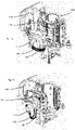
- Figure 1a shows a forming device according to the applicant's internal prior art in a closed state.
- This has a first side part carrier 142 and a second side part carrier 144 .
- These two side part supports 142 and 144 are arranged pivotably relative to a main support 106 .
- the reference number 112 designates a fastening device, by means of which two hose lines 182 and 184 are fastened to the main beam. The second ends of these hose lines open out here in an area of the side part support 142.
- Figure 1b shows the in Figure 1a shown forming device in an open state. It can be seen that here the side part supports move much closer to the fastening device 112 and in this way the hose lines 182, 184 are curved to a much greater extent and are therefore subjected to a much greater load.
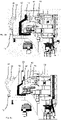
- Figure 2a shows a forming device according to the invention in a closed state.
- Reference number 42 refers to a first side part carrier and reference number 44 to a second side part carrier.
- These side part supports can be pivoted by means of a shaft to open and close the blow mold (not shown).
- the reference number 30 designates a locking device, by means of which the side part supports can be locked.
- the reference numeral 72 denotes a base part carrier, by means of which a base part (not shown) can also be brought up to the two side parts in order to close the blow mold.
- the reference number 70 designates a coupling mechanism, by means of which the movement of the base part carrier 72 is coupled to the movement of the side part carriers.
- Reference number 54 designates a drive device, here a cam roller, by means of which (with guide curves) the blow molds can be opened and closed.
- the reference number 12 designates a fastening device which is arranged on the main beam 6 .
- two first connecting line sections 92 and 94 lead to an actuator 14.
- two connecting line sections 82 and 84 in turn lead further to the blow mold support part 42 and two further connecting line sections 86 and 88 to the second side part support 44.
- Reference number 1 denotes the reshaping device and reference numeral 50 the reshaping device.
- Figure 2b shows the in figure 1 shown forming device in an open state. It can be seen that here the connecting line sections 82 and 84 are not significantly more curved than in the case of FIG Figure 2a Situation shown, since the actuator 14 with the opening movement here compared to figure 2 moved backwards.
- the reference numeral 52 designates an actuator carrier, which in turn is arranged on a carriage, the movement of which is mechanically coupled to the guide roller.
- the Figures 3a and 3b show a side view of the in the Figures 2a and 2b shown forming device.
- the carriage 52 is shown in particular, which (cf. figure 3 ) is placed in two different positions.
- the actuator 14 is also arranged on this carriage.
- the reference numeral 52′ accordingly indicates the position of the carrier 52 in FIG Figure 3a shown situation.
- FIGS. 4a and 4b show a plan view of the forming device according to the invention.
- the distance D1 along which the actuator 14 is moved can also be seen here in particular.
- the actuator also serves to distribute liquids to the two side part supports 42 and 44.
- the actuator 14 has a cavity in its interior in which liquid can be collected and/or distributed.
- figure 5 shows a schematic representation of an arrangement according to the invention for shaping plastic preforms 10 into plastic containers 20.
- This has a station support 15 on which a large number of shaping stations 1 and in particular shaping stations 1 according to the invention are arranged.
- Reference numerals 22 and 24 denote, roughly schematically, the side parts of a blow mold 2.
Landscapes
- Engineering & Computer Science (AREA)
- Manufacturing & Machinery (AREA)
- Mechanical Engineering (AREA)
- Blow-Moulding Or Thermoforming Of Plastics Or The Like (AREA)
- Moulds For Moulding Plastics Or The Like (AREA)
Description
Die vorliegende Erfindung bezieht sich auf eine Vorrichtung und ein Verfahren zum Umformen von Kunststoffvorformlingen zu Kunststoffbehältnissen. Derartige Vorrichtungen und Verfahren sind aus dem Stand der Technik seit langem bekannt. Dabei werden üblicherweise erwärmte Kunststoffvorformlinge innerhalb von Blasformen zu Kunststoffbehältnissen, wie insbesondere Kunststoffflaschen expandiert. Dies kann dabei mit gasförmigen Medien, wie insbesondere Druckluft, geschehen, neuerdings sind jedoch auch Verfahren bekannt geworden, bei denen diese Expansion unmittelbar mit einem flüssigen Medium und insbesondere mit einem beispielsweise abzufüllenden Getränk erfolgt. Die vorliegende Erfindung ist auf beide Ausgestaltungen gerichtet. Solche Vorrichtungen und Verfahren aus dem Stand der Technik sind in den Dokumente
Üblicherweise weisen derartige Umformungsstationen Blasformträger auf, an denen mittelbar oder unmittelbar Blasformteile angeordnet sind. Teilweise ist es erforderlich, diese Blasformteile oder andere Bestandteile der Umformungsstationen wie etwa Blasformträgerschalen oder auch die Blasformträger selbst zu versorgen, beispielsweise mit elektrischer Energie, aber auch insbesondere mit Temperiermedien. Zu diesem Zweck werden üblicherweise Kabel und Leitungen eingesetzt. Beim Öffnen und Schließen dieser Blasformen werden die Blasformträger üblicherweise geschwenkt. So kann es zu erhöhten Belastungen dieser Leitungsverbindungen kommen, was insofern nachteilig ist, da diese Verbindungen oft teuer sind und daher relativ schnell ausgewechselt werden.Such forming stations usually have blow mold carriers on which blow mold parts are arranged directly or indirectly. It is sometimes necessary to supply these blow mold parts or other components of the forming stations, such as blow mold carrier shells or the blow mold carriers themselves, for example with electrical energy, but also in particular with temperature control media. Cables and wires are usually used for this purpose. When opening and closing these blow molds, the blow mold carriers are usually pivoted. This can lead to increased loads on these line connections, which is disadvantageous in that these connections are often expensive and can therefore be replaced relatively quickly.
Insbesondere zur Temperierung des Formträgers oder der Blasformteile einer solchen Blas- oder Umformungsstation werden diese von einem Temperiermedium durchflossen. Aufgrund der erforderlichen Bewegung des Formträgers muss daher dieser über eine flexible Schlauchleitung mit dem Temperiermedium versorgt werden. Nach dem heutigen Stand der Technik werden diese Schlauchleitungen an der einen Seite fest eingebaut, das heißt eine Seite des Schlauchs wird an einem Verteiler angeschlossen und die andere Seite an dem beweglichen Formträger.In particular for temperature control of the mold carrier or the blow mold parts of such a blow molding or forming station, a temperature control medium flows through them. Due to the required movement of the mold carrier, it must therefore be supplied with the temperature control medium via a flexible hose line. According to the current state of the art, these hose lines are permanently installed on one side, i.e. one side of the hose is connected to a distributor and the other side to the movable mold carrier.
Wie oben erwähnt kommt es damit bei einer Öffnungs- und Schließbewegung zu Torsionen und dergleichen dieser Schläuche und damit zu einer hohen Belastung.As mentioned above, torsions and the like of these hoses occur during an opening and closing movement, and thus a high load.
Der vorliegenden Erfindung liegt daher weiterhin die Aufgabe zugrunde, derartige Belastungen zu reduzieren und insbesondere auf diese Weise die Lebensdauer derartiger Verbindungsleitungen zu erhöhen. Diese Aufgaben werden erfindungsgemäß durch die Gegenstände der unabhängigen Patentansprüche erreicht.The present invention is therefore also based on the object of reducing such loads and, in particular, increasing the service life of such connecting lines in this way. According to the invention, these objects are achieved by the subject matter of the independent patent claims.
Vorteilhafte Ausführungsformen und Weiterbildungen sind Gegenstand der Unteransprüche.Advantageous embodiments and developments are the subject of the dependent claims.
Eine erfindungsgemäße Vorrichtung zum Umformen von Kunststoffvorformlingen zu Kunststoffbehältnissen weist eine Umformungseinheit mit einem ersten Seitenteilträger und einem zweiten Seitenteilträger auf. Dabei ist an dem ersten Seitenteilträger ein erstes Seitenteil einer Blasform zumindest mittelbar befestigbar und an dem zweiten Seitenteilträger ist ein zweites Seitenteil einer Blasform zumindest mittelbar befestigbar, wobei diese Seitenteile in einem geschlossenen Zustand der Blasform wenigstens einen Teil des Hohlraums ausbilden, innerhalb dessen der Kunststoffvorformling durch Beaufschlagung mit einem fließfähigen Medium zu dem Kunststoffbehältnis umformbar ist und wobei die Umformungseinrichtung an einem Hauptträger angeordnet ist, an dem wenigstens ein Seitenteilträger bewegbar gegenüber dem anderen Seitenteilträger zum Öffnen und/oder Schließen der Blasform angeordnet ist.A device according to the invention for forming plastic preforms into plastic containers has a forming unit with a first side part carrier and a second side part carrier. A first side part of a blow mold can be fastened at least indirectly to the first side part carrier and a second side part of a blow mold can be fastened at least indirectly to the second side part carrier, with these side parts forming at least part of the cavity when the blow mold is in a closed state, within which the plastic preform passes through Being subjected to a flowable medium can be formed into the plastic container and the forming device is arranged on a main carrier on which at least one side part carrier is arranged so that it can be moved relative to the other side part carrier for opening and/or closing the blow mold.
Dabei weist die Umformungseinrichtung wenigstens eine Versorgungseinrichtung mit wenigstens einer ersten Verbindungsleitung auf, wobei wenigstens ein Abschnitt wenigstens einer Verbindungsleitung mittels einer Befestigungseinrichtung stationär gegenüber dem Hauptträger angeordnet ist und wobei ein Abschnitt dieser Verbindungsleitung an einer Einrichtung der Umformungseinheit angeordnet ist, derart, dass sich bei einer Bewegung des Seitenteilträgers gegenüber dem Hauptträger dieser Abschnitt der Verbindungsleitung gegenüber der Befestigungseinrichtung bewegt.The forming device has at least one supply device with at least one first connecting line, with at least one section of at least one connecting line being arranged in a stationary manner opposite the main beam by means of a fastening device, and with a section of this connecting line being attached to a device the forming unit is arranged in such a way that when the side part carrier moves relative to the main carrier, this section of the connecting line moves relative to the fastening device.
Erfindungsgemäß weist die Vorrichtung ein Stellglied auf, an dem wenigstens ein Abschnitt und insbesondere ein weiterer Abschnitt der Verbindungsleitung befestigt ist, wobei dieses Stellglied ebenfalls gegenüber dem Hauptträger bewegbar ist.According to the invention, the device has an actuator to which at least one section and in particular a further section of the connecting line is attached, this actuator also being movable with respect to the main support.
Insbesondere ist dieser weitere Abschnitt der Verbindungsleitung von demjenigen Abschnitt, der an der Einrichtung der Umformungseinrichtung angeordnet ist und/oder demjenigen Abschnitt, der an der Befestigungseinrichtung angeordnet ist, beabstandet. Insbesondere ist dieser Abschnitt zwischen dem Abschnitt, der an der Einrichtung der Umformungseinrichtung angeordnet ist und demjenigen Abschnitt, der an der Befestigungseinrichtung angeordnet istIn particular, this further section of the connecting line is at a distance from that section which is arranged on the device of the reshaping device and/or that section which is arranged on the fastening device. In particular, this section is between the section that is arranged on the device of the forming device and that section that is arranged on the fastening device
Bei einer weiteren vorteilhaften Ausführungsform weist die Blasform auch ein Bodenteil auf. Besonders bevorzugt bilden die beiden Seitenteile gemeinsam mit diesem Bodenteil den Hohlraum zum Expandieren der Kunststoffvorformlinge zu den Kunststoffbehältnissen aus. Dabei kann weiterhin auch eine Vorrichtung vorgesehen sein, welche zum Schließen der Blasform das Bodenteil an diese zustellt.In a further advantageous embodiment, the blow mold also has a base part. Particularly preferably, the two side parts, together with this base part, form the cavity for expanding the plastic preforms into the plastic containers. Furthermore, a device can also be provided which advances the base part to the blow mold in order to close it.
Die Erfindung schlägt daher vor, dass eine Entlastung dieser Verbindungsleitung dadurch vorgenommen wird, dass ein Abschnitt, an dem die Verbindungsleitung befestigt ist, (insbesondere gekoppelt an die Bewegung der Seitenteilträger) ebenfalls bewegt wird, um so ein übermäßiges Verdrillen oder Verbiegen der Verbindungsleitung zu verhindern.The invention therefore proposes that this connection line be relieved in that a section to which the connection line is attached is also moved (in particular coupled to the movement of the side part supports) in order to prevent excessive twisting or bending of the connection line .
Bei einer weiteren vorteilhaften Ausführungsform weist die Vorrichtung einen stangenartigen Körper und insbesondere einer Reckstange auf, welche zum Dehnen der Kunststoffvorformlinge in diese einführbar ist.In a further advantageous embodiment, the device has a rod-like body and in particular a stretching rod, which can be inserted into the plastic preforms in order to stretch them.
Bei einer weiteren vorteilhaften Ausführungsform weist die Vorrichtung auch eine Beaufschlagungseinrichtung auf, welche den Kunststoffvorformling mit dem fließfähigen Medium beaufschlagt. Wie oben erwähnt, kann dabei diese Beaufschlagungseinrichtung etwa eine sogenannte Blasdüse sein, welche an einem Mündungsrand der Kunststoffvorformlinge anlegbar ist und diese mit dem fließfähigen Medium beaufschlagt. Dabei kann diese Beaufschlagungseinrichtung die Kunststoffvorformlinge sowohl mit einem gasförmigen Medium beaufschlagen, als auch mit einem flüssigen Medium und insbesondere einem abzufüllenden Getränk.In a further advantageous embodiment, the device also has an application device which applies the flowable medium to the plastic preform. As mentioned above, this application device can be a so-called blowing nozzle, for example, which can be placed against a mouth edge of the plastic preforms and applies the flowable medium to them. In this case, this application device subject the plastic preforms both to a gaseous medium and to a liquid medium and in particular a beverage to be filled.
Bei einer weiteren vorteilhaften Ausführungsform ist es möglich, dass die Seitenteile der Blasformeinrichtung unmittelbar an den Seitenteilträgern angeordnet sind, es wäre jedoch auch möglich, dass noch weitere Elemente vorgesehen sind. So können beispielsweise an den Seitenteilträgern Blasformschalen angeordnet sein und an diesen Blasformschalen wiederum die Blasformseitenteile.In a further advantageous embodiment, it is possible for the side parts of the blow molding device to be arranged directly on the side part supports, but it would also be possible for further elements to be provided. For example, blow mold shells can be arranged on the side part supports and the blow mold side parts can in turn be arranged on these blow mold shells.
Bei einer weiteren bevorzugten Ausführungsform ist die Bewegung des wenigstens einen Seitenteilträgers eine Schwenkbewegung und insbesondere eine Schwenkbewegung bezüglich einer Achse, welche parallel ist zu der Längsrichtung des umzuformenden Kunststoffvorformlings. Besonders bevorzugt wird auch der zweite Seitenteilträger geschwenkt. Dabei kann es sich um einen symmetrischen Schwenkvorgang handeln, sodass die beiden Seitenteilträger gleichermaßen und auch mit der gleichen Geschwindigkeit geschwenkt werden.In a further preferred embodiment, the movement of the at least one side part carrier is a pivoting movement and in particular a pivoting movement with respect to an axis which is parallel to the longitudinal direction of the plastic preform to be shaped. The second side part support is also particularly preferably pivoted. This can involve a symmetrical pivoting process, so that the two side part supports are pivoted equally and also at the same speed.
Unter einer Anordnung der Verbindungsleitung an wenigstens einer Einrichtung der Umformungseinheit wird verstanden, dass diese beispielsweise an dem Seitenteilträger angeordnet werden kann. Zu diesem Zweck kann die Leitungseinrichtung entsprechende Kupplungseinrichtungen aufweisen. Es wäre jedoch auch möglich, dass sich die Verbindungsleitung abschnittsweise durch den Seitenteilträger hindurch erstreckt, um innerhalb der Seitenteilträgers angeordnete Elemente, wie insbesondere die Seitenteile der Blasform unmittelbar zu versorgen, etwa mit dem Temperiermedium zu temperieren.Arranging the connecting line on at least one device of the reshaping unit means that it can be arranged on the side part carrier, for example. For this purpose, the line device can have corresponding coupling devices. However, it would also be possible for the connecting line to extend in sections through the side part carrier in order to directly supply elements arranged within the side part carrier, such as in particular the side parts of the blow mold, for example with the temperature control medium.
Bei einer weiteren vorteilhaften Ausführungsform handelt es sich bei demjenigen Abschnitt, der an der Einrichtung der Umformungseinheit angeordnet ist, um einen Endabschnitt der Verbindungsleitung.In a further advantageous embodiment, that section which is arranged on the device of the shaping unit is an end section of the connecting line.
Unter einer Versorgung der Umformungsstation wird insbesondere die Versorgung der Umformungsstation mit einem fließfähigen, beispielsweise flüssigen Medium verstanden. Es könnte sich jedoch auch um die Versorgung der Umformungsstation mit elektrischer Energie handeln, beispielsweise wenn die Blasformteile elektrisch temperiert, beispielsweise erwärmt werden.Supplying the forming station is understood to mean, in particular, supplying the forming station with a free-flowing, for example liquid, medium. However, it could also be a matter of supplying the forming station with electrical energy, for example if the blow-molded parts are electrically temperature-controlled, for example heated.
Es wird daher vorgeschlagen, dass die im Stand der Technik an einem unbeweglichen Verteiler angeschlossenen Leitungsstücke nur an einem Verteiler angeschlossen werden, der insbesondere mit den Seitenteilträgern gekoppelt ist, wobei sich dieser Verteiler, im Folgenden als Stellglied bezeichnet -bevorzugt synchron- mit der Öffnungs- und Schließbewegung des Formträgers bewegt. Dieses Stellglied, bzw. dieser Verteilerklotz wird bevorzugt mit einem zusätzlichen Schlauch versorgt. Dies ist unten genauer erläutert.It is therefore proposed that the line sections connected to a stationary distributor in the prior art are only connected to one distributor, which is coupled in particular to the side part supports, with this distributor, referred to below as the actuator -preferably synchronously- with the opening and closing movement of the mold carrier moves. This actuator or this distributor block is preferably supplied with an additional hose. This is explained in more detail below.
Besonders bevorzugt ist die Bewegung des Stellglieds an die Bewegung wenigstens eines Seitenteilträgers und bevorzugt beider Seitenteilträger gekoppelt.The movement of the actuator is particularly preferably coupled to the movement of at least one side part carrier and preferably both side part carriers.
Bei einer weiteren bevorzugten Ausführungsform ist ein Antrieb zum Öffnen und Schließen der Blasform vorgesehen. Dieser kann beispielsweise ein elektrischer Antrieb oder auch ein pneumatischer oder hydraulischer Antrieb sein, es wäre jedoch auch denkbar und bevorzugt, dass zum Durchführen der Öffnungs- und Schließbewegung Führungskurven verwendet werden.In a further preferred embodiment, a drive for opening and closing the blow mold is provided. This can be, for example, an electric drive or a pneumatic or hydraulic drive, but it would also be conceivable and preferable for guide cams to be used to carry out the opening and closing movement.
Bei einer weiteren vorteilhaften Ausführungsform handelt es sich bei der Verbindungsleitung um eine Medienleitung und insbesondere um eine Flüssigkeitsleitung. Besonders bevorzugt dienen diese Medienleitungen zum Leiten eines flüssigen oder gasförmigen Mediums, beispielsweise Wasser oder Öl. Insbesondere dient die Versorgungseinrichtung zum Temperieren von Elementen der Umformungseinrichtung und insbesondere von den Blasformseitenteilen.In a further advantageous embodiment, the connecting line is a media line and in particular a liquid line. These media lines are particularly preferably used for conducting a liquid or gaseous medium, for example water or oil. In particular, the supply device serves to control the temperature of elements of the forming device and in particular of the blow mold side parts.
Bevorzugt handelt es sich bei den Medienleitungen um Schläuche.The media lines are preferably hoses.
Bei einer weiteren vorteilhaften Ausführungsform handelt es sich bei wenigstens einer Verbindungsleitung um eine flexible Verbindungsleitung. Bevorzugt mündet dabei ein Endabschnitt dieser Verbindungsleitung in den Seitenteilträgern der Blasform.In a further advantageous embodiment, at least one connecting line is a flexible connecting line. An end section of this connecting line preferably opens into the side part supports of the blow mold.
Bei einer weiteren vorteilhaften Ausführungsform ist eine Bewegung des Stellglieds gegenüber dem Hauptträger an eine Bewegung wenigstens eines Seitenteilträgers gegenüber dem Hauptträger gekoppelt. Dabei erfolgt insbesondere eine mechanische Kopplung. So kann beispielsweise durch eine Bewegung des Seitenteilträgers auch ein Schlitten in Bewegung gesetzt werden, der wiederum das Stellglied trägt.In a further advantageous embodiment, a movement of the actuator relative to the main support is coupled to a movement of at least one side part support relative to the main support. In this case, in particular, a mechanical coupling takes place. For example, a movement of the side part carrier can also set a carriage in motion, which in turn carries the actuator.
Auf diese Weise wird die komplexe und ungünstige Bewegung der Schläuche auf wenigstens zwei Abschnitte aufgeteilt.In this way the complex and awkward movement of the hoses is divided into at least two sections.
Bei einer weiteren bevorzugten Ausführungsform ist die Bewegung des Stellglieds derart an die Bewegung des Seitenteilträgers gekoppelt, dass diese Bewegung einer Abstandsänderung zwischen dem Seitenteilträger und dem Stellglied entgegenwirkt. Insbesondere handelt es sich dabei um eine Abstandsänderung zwischen den Endabschnitten der jeweiligen Verbindungsleitung.In a further preferred embodiment, the movement of the actuator is coupled to the movement of the side part carrier in such a way that this movement counteracts a change in the distance between the side part carrier and the actuator. In particular, this involves a change in distance between the end sections of the respective connecting line.
Bei einer weiteren vorteilhaften Ausführungsform weist wenigstens eine Verbindungsleitung einen ersten Verbindungsleitungsabschnitt auf und wenigstens einen zweiten Verbindungsleitungsabschnitt auf, wobei der erste Verbindungsleitungsabschnitt und der zweite Verbindungsleitungsabschnitt miteinander in Strömungsverbindung stehen. Dabei ist es möglich, dass diese Verbindungsleitungsabschnitte miteinander gekoppelt sind, beispielsweise über Kopplungen. Besonders bevorzugt wird jedoch diese Strömungsverbindung durch das Stellglied hergestellt.In a further advantageous embodiment, at least one connecting line has a first connecting line section and at least one second connecting line section, the first connecting line section and the second connecting line section being flow-connected to one another. In this case, it is possible for these connecting line sections to be coupled to one another, for example via couplings. However, this flow connection is particularly preferably established by the actuator.
Bei einer bevorzugten Ausführungsform ist das Stellglied in einer geradlinigen Richtung bewegbar. Bevorzugt wird dabei, wie unten genauer erläutert wird, ein Schlitten vorgesehen, der das Stellglied trägt bzw. der mechanisch mit diesem gekoppelt ist. Dabei ist es möglich, dass das Stellglied von der gleichen Antriebseinrichtung bewegt wird, welche auch eine Bewegung der Seitenteilträger bewirkt.In a preferred embodiment, the actuator is movable in a linear direction. As will be explained in more detail below, a carriage is preferably provided which carries the actuator or which is mechanically coupled to it. It is possible for the actuator to be moved by the same drive device that also causes the side part carriers to move.
Besonders bevorzugt kann diese geradlinige Bewegung im Wesentlichen auch senkrecht zu einer Achse des Kunststoffvorformlings sein. Es wäre jedoch auch möglich, dass die Bewegung schräg gegenüber der Achse des Kunststoffvorformlings ist, beispielsweise gegenüber einer senkrechten Richtung bezüglich der Längsrichtung des Kunststoffvorformlings, um weniger als 30°, bevorzugt um weniger als 20° und bevorzugt um weniger als 10° geneigt ist.Particularly preferably, this linear movement can also be essentially perpendicular to an axis of the plastic preform. However, it would also be possible for the movement to be oblique to the axis of the plastic preform, for example to a perpendicular direction with respect to the longitudinal direction of the plastic preform, by less than 30°, preferably by less than 20° and preferably by less than 10°.
Bei einer weiteren vorteilhaften Ausführungsform sind die Blasformträgerteile symmetrisch bewegbar.In a further advantageous embodiment, the blow mold carrier parts can be moved symmetrically.
Bei einer weiteren vorteilhaften Ausführungsform ist das Stellglied in einer Symmetrieebene bewegbar, die in einem geschlossenen Zustand der Blasform durch die beiden aneinander liegenden Seitenteile der Blasform gebildet wird. Auf diese Weise kann für beide Blasformträgerteile eine gleichwertige Entlastung erreicht werden. Durch die Verwendung von mehreren Verbindungsabschnitten der Leitungsverbindungen wird die komplexe und ungünstige Schlauchbewegung des ursprünglichen Schlauches auf zwei Schläuche aufgeteilt. Diese Schläuche müssen dann eine erheblich kleinere Bewegung vollziehen. Dabei handelt es sich jedoch nur noch um eine sehr leichte Bewegung und Torsionen können bevorzugt vollständig vermieden werden.In a further advantageous embodiment, the actuator can be moved in a plane of symmetry, which in a closed state of the blow mold through the two together lying side parts of the blow mold is formed. In this way, equal relief can be achieved for both blow mold carrier parts. By using multiple connection sections of the line connections, the complex and unfavorable hose movement of the original hose is divided into two hoses. These hoses then have to perform a considerably smaller movement. However, this is only a very slight movement and torsion can preferably be completely avoided.
Der Schlauch bzw. die Schläuche können dadurch aus einem deutlich günstigeren Schlauchmaterial gefertigt werden. Auf diese Weise kann auch eine Kosteneinsparung bei den Verbindungsleitungen erreicht werden. Insgesamt wird hier trotz der Erhöhung der Anzahl der Schläuche ein Kostenvorteil erreicht.As a result, the hose or hoses can be manufactured from a significantly cheaper hose material. In this way, cost savings can also be achieved for the connecting lines. Overall, a cost advantage is achieved here despite the increase in the number of hoses.
Bei einer weiteren vorteilhaften Ausführungsform ist das Stellglied auch als Flüssigkeitsverteileinrichtung ausgebildet. So kann das Stellglied einen Verteilraum aufweisen, der beispielsweise die Flüssigkeit von einem zuführenden Leitungsabschnitt auf zwei abführende Leitungsabschnitte verteilt. Dies gilt insbesondere für den Vorlauf einer Temperierung für die Blasformen. Entsprechend kann für den Rücklauf das Stellglied auch als Verteilereinrichtung bzw. als Sammeleinrichtung wirken, welche den Rückstrom von zwei zweiten Leitungsabschnitten sammelt und einen ersten Leitungsabschnitt zuführt.In a further advantageous embodiment, the actuator is also designed as a liquid distribution device. The actuator can thus have a distribution space which, for example, distributes the liquid from a supplying line section to two discharging line sections. This applies in particular to the pre-run of temperature control for the blow moulds. Correspondingly, for the return, the actuator can also act as a distributor device or as a collection device, which collects the return flow from two second line sections and supplies it to a first line section.
Die vorliegende Erfindung ist weiterhin auf eine Anordnung zum Umformen von Kunststoffvorformlingen zu Kunststoffbehältnissen mit einem bewegbaren und insbesondere drehbaren Zentralträger gerichtet, an dem eine Vielzahl von Vorrichtungen der oben beschriebenen Ansprüche befestigt ist. Insbesondere handelt es sich dabei um eine Anordnung vom Rundläufertyp.The present invention is also aimed at an arrangement for forming plastic preforms into plastic containers with a movable and in particular rotatable central support, to which a multiplicity of devices of the claims described above are attached. In particular, this is an arrangement of the rotary type.
Bei einer bevorzugten Ausführungsform weist die Anordnung eine Zuführeinrichtung und insbesondere einen Zuführstern auf, um die Kunststoffvorformlinge an die jeweiligen Umformungsstationen zuzuführen. Bei einer weiteren vorteilhaften Ausführungsform weist die Anordnung auch eine Abführeinrichtung und insbesondere einen Abführstern auf, um die gefertigten und insbesondere geblasenen und/ oder bereits gefüllten Behältnisse von den Umformungsstationen abzuführen.In a preferred embodiment, the arrangement has a feed device and in particular a feed star wheel in order to feed the plastic preforms to the respective forming stations. In a further advantageous embodiment, the arrangement also has a discharge device and in particular a discharge star wheel in order to discharge the manufactured and in particular blown and/or already filled containers from the forming stations.
Die vorliegende Erfindung ist weiterhin auf ein Verfahren zum Umformen von Kunststoffvorformlingen zu Kunststoffbehältnissen mittels einer Umformungseinheit gerichtet, welche einen ersten Seitenteilträger und einen zweiten Seitenteilträger aufweist, wobei an dem ersten Seitenteilträger ein erstes Seitenteil einer Blasform zumindest mittelbar befestigt ist bzw. befestigt wird und an dem zweiten Seitenteilträger ein zweites Seitenteil der Blasform wenigstens mittelbar befestigt ist bzw. befestigt wird und wobei diese Seitenteile in einem geschlossenen Zustand der Blasform wenigstens einen Teil eines Hohlraums ausbilden, innerhalb dessen der Kunststoffvorformling durch Beaufschlagung mit einem fließfähigen Medium zu dem Kunststoffbehältnis umgeformt wird und wobei die Umformungseinheit an einem Hauptträger angeordnet ist, an dem wenigstens ein Seitenteilträger gegenüber dem anderen Seitenteilträger zum Öffnen und/oder Schließen der Blasform bewegt wird, wobei wenigstens ein Element der Umformungseinheit mittels einer Versorgungseinrichtung versorgt wird und welche wenigstens eine erste Verbindungsleitung aufweist, wobei wenigstens ein Abschnitt wenigstens einer Verbindungsleitung mittels wenigstens einer Befestigungseinrichtung stationär gegenüber dem Hauptträger angeordnet wird und wobei ein Abschnitt dieser Verbindungsleitung an einer Einrichtung der Umformungseinheit angeordnet wird, derart, dass sich bei einer Bewegung des Seitenteilträgers gegenüber dem Hauptträger dieser Abschnitt der Verbindungsleitung gegenüber der Befestigungseinrichtung und/oder dem Hauptträger bewegt.The present invention is also directed to a method for forming plastic preforms into plastic containers by means of a forming unit which has a first side part carrier and a second side part carrier, with a first side part of a blow mold being or being fastened at least indirectly to the first side part carrier and to which second side part carrier a second side part of the blow mold is or will be attached at least indirectly and wherein these side parts form at least part of a cavity when the blow mold is in a closed state, within which the plastic preform is formed into the plastic container by being subjected to a flowable medium and wherein the Forming unit is arranged on a main carrier, on which at least one side part carrier is moved relative to the other side part carrier for opening and/or closing the blow mold, with at least one element of the order forming unit is supplied by means of a supply device and which has at least one first connecting line, with at least one section of at least one connecting line being arranged in a stationary manner opposite the main support by means of at least one fastening device, and with a section of this connecting line being arranged on a device of the forming unit in such a way that at a movement of the side part carrier relative to the main carrier moves this section of the connecting line relative to the fastening device and/or the main carrier.
Erfindungsgemäß weist die Vorrichtung ein Stellglied auf, an dem wenigstens ein Abschnitt der Verbindungsleitung befestigt ist, wobei sich dieses Stellglied beim Öffnen und/oder Schließen der Blasform ebenfalls gegenüber dem Hauptträger bewegt.According to the invention, the device has an actuator to which at least one section of the connecting line is attached, this actuator also moving relative to the main support when the blow mold is opened and/or closed.
Es wird daher auch verfahrensseitig eine Vorgehensweise vorgeschlagen, welche letztlich zur Entlastung der jeweiligen Verbindungsleitungen, insbesondere Schläuche, führt.A procedure is therefore also proposed in terms of the method, which ultimately leads to the relief of the respective connecting lines, in particular hoses.
Bevorzugt werden die Kunststoffvorformlinge mittels eines fließfähigen Mediums und insbesondere mittels Luft und/oder einer Flüssigkeit expandiert.The plastic preforms are preferably expanded by means of a flowable medium and in particular by means of air and/or a liquid.
Weitere Vorteile und Ausführungsformen ergeben sich aus den beigefügten Zeichnungen.Further advantages and embodiments result from the accompanying drawings.
Darin zeigen:
- Fig. 1a
- Eine Darstellung einer Umformungsstation nach dem internen Stand der Technik der Anmelderin in einem geschlossenen Zustand;
- Fig. 1b
- Die Umformungseinrichtung aus
Fig. 1a in einem geöffneten Zustand; - Fig. 2a
- Eine Darstellung einer erfindungsgemäßen Umformungseinrichtung in einem geschlossenen Zustand der Blasform bzw. Umformungseinheit;
- Fig.2b
- Die Vorrichtung aus
Figur 2a in einem geöffneten Zustand der Blasform bzw. Umformungseinheit; - Fig. 3a
- Eine Seitenansicht der Umformungseinrichtung in einem geschlossenen Zustand der Blasform;
- Fig. 3b
- Eine Seitenansicht der Umformungseinrichtung in einem geöffneten Zustand der Blasform;
- Fig. 4a
- Eine Ansicht von unten auf eine erfindungsgemäße Umformungseinrichtung in einem geschlossenen Zustand der Blasform;
- Fig. 4b
- Die Darstellung aus
Fig. 4a in einem geöffneten Zustand der Blasform; und - Fig. 5
- Eine schematische Darstellung einer Anordnung zum Umformen von Kunststoffvorformlingen zu Kunststoffbehältnissen.
- Fig. 1a
- An illustration of applicant's internal prior art forming station in a closed condition;
- Fig. 1b
- The conversion device off
Fig. 1a in an open state; - Figure 2a
- A representation of a forming device according to the invention in a closed state of the blow mold or forming unit;
- Fig.2b
- The device off
Figure 2a in an open state of the blow mold or forming unit; - Figure 3a
- A side view of the forming device in a closed state of the blow mold;
- Figure 3b
- A side view of the forming device in an open state of the blow mold;
- Figure 4a
- A view from below of a shaping device according to the invention in a closed state of the blow mold;
- Figure 4b
- The representation off
Figure 4a in an open state of the blow mold; and - figure 5
- A schematic representation of an arrangement for forming plastic preforms into plastic containers.
Das Bezugszeichen 72 kennzeichnet einen Bodenteilträger, mittels dessen ein (nicht gezeigtes) Bodenteil ebenfalls an die beiden Seitenteile herangeführt werden kann, um so die Blasform zu schließen. Das Bezugszeichen 70 kennzeichnet einen Kopplungsmechanismus, mittels dessen die Bewegung des Bodenteilträgers 72 an die Bewegung der Seitenteilträger gekoppelt ist.The
Das Bezugszeichen 54 kennzeichnet eine Antriebseinrichtung, hier eine Kurvenrolle, mittels der (mit Führungskurven) ein Öffnen und Schließen der Blasformen erreicht werden kann.
Das Bezugszeichen 12 kennzeichnet eine Befestigungseinrichtung, die an dem Hauptträger 6 angeordnet ist. Ausgehend von dieser Befestigungseinrichtung führen zwei erste Verbindungsleitungsabschnitte 92 und 94 zu einem Stellglied 14. Ausgehend von diesem Stellglied 14 führen wiederum zwei Verbindungsleitungsabschnitte 82 und 84 weiter zu dem Blasformträgerteil 42 und zwei weitere Verbindungsleitungsabschnitte 86 und 88 zu dem zweiten Seitenteilträger 44. Das Bezugszeichen 1 kennzeichnet die Umformungseinrichtung und das Bezugszeichen 50 die Umformungsvorrichtung.The
Das Bezugszeichen 52 kennzeichnet einen Stellgliedträger, der wiederum an einem Schlitten angeordnet ist, dessen Bewegung mechanisch mit der Führungsrolle gekoppelt ist.The
Die
Die
Wie oben erwähnt, dient das Stellglied auch zum Verteilen von Flüssigkeiten auf die beiden Seitenteilträger 42 und 44. Entsprechend weist das Stellglied 14 in seinem Inneren einen Hohlraum auf, in dem Flüssigkeit gesammelt und/oder verteilt werden kann.As mentioned above, the actuator also serves to distribute liquids to the two side part supports 42 and 44. Correspondingly, the
- 11
- Umformungseinrichtungforming device
- 22
- Blasformblow mold
- 66
- Hauptträgermain carrier
- 1010
- Kunststoffvorformlingeplastic preforms
- 1212
- Befestigungseinrichtungfastening device
- 1414
- Stellgliedactuator
- 1515
- Stationsträgerstation carrier
- 2020
- Kunststoffbehältnisseplastic containers
- 2222
- Seitenteil einer BlasformSide part of a blow mould
- 2424
- Seitenteil einer BlasformSide part of a blow mould
- 3030
- Verriegelungseinrichtunglocking device
- 4242
- Blasformträgerteilblow mold carrier part
- 4242
- erster Seitenteilträgerfirst side panel carrier
- 4444
- zweiter Seitenteilträgersecond side part carrier
- 5050
- Umformungsstationforming station
- 5252
- Stellgliedträger, Schlittenactuator carrier, slide
- 52'52'
- Position des Trägersposition of the wearer
- 5353
- Führungsrolleleadership role
- 5454
- Antriebseinrichtungdrive device
- 7070
- Kopplungsmechanismuscoupling mechanism
- 7272
- Seitenteil einer BlasformSide part of a blow mould
- 8282
- Leitungsabschnittline section
- 8484
- Leitungsabschnittline section
- 8686
- Verbindungsleitungsabschnittconnecting line section
- 8888
- Verbindungsleitungsabschnittconnecting line section
- 9292
- erster Leitungsabschnittfirst line section
- 9494
- erster Leitungsabschnittfirst line section
- 106106
- Hauptträger (Stand der Technik)Main beam (state of the art)
- 112112
- Befestigungseinrichtung (Stand der Technik)Fastening device (state of the art)
- 142142
- erster Seitenteilträger (Stand der Technik)first side part carrier (state of the art)
- 144144
- zweiter Seitenteilträger (Stand der Technik)second side part carrier (state of the art)
- 182182
- Schlauchleitung (Stand der Technik)hose line (state of the art)
- 184184
- Schlauchleitung (Stand der Technik)hose line (state of the art)
Claims (10)
- Apparatus (50) for forming plastic preforms (10) into plastic containers (20), having a forming device (1) with a first side part carrier (42) and a second side part carrier (44), wherein a first side part (22) of a blow mould (2) is fastened at least indirectly at the first side part carrier (42) and a second side part (24) of the blow mould (2) is fastened at least indirectly at the second side-part carrier (44), wherein these side parts (22, 24) in a closed state of the blow mould (2) form at least a part of a cavity within which the plastic preform (10) can be formed into the plastic container (20) by the application of a flowable medium, and wherein the forming device (1) is arranged on a main carrier (6), on which at least one side part carrier (42) is arranged movably relative to the other side part carrier (44) for opening and/or closing the blow mould (2), wherein the forming device (1) has at least one supply device (8) with at least one first connecting line (82, 84, 86, 88, 92, 94), wherein at least one section of at least one connecting line (82, 84, 86, 88, 92, 94) is arranged stationary with respect to the main carrier (6) by means of at least one fastening device (12) and wherein a section of this connecting line (82, 84, 86, 88, 92, 94) being arranged on a device of the forming device (1) in such a way that, in the event of a movement of the side part carrier (42, 44) with respect to the main carrier (6), this section of the connecting line (82, 84, 86, 88, 92, 94) moves with respect to the fastening device (14), characterized in that
an actuator (14) is arranged on the apparatus (50), to which at least one section of the connecting line (82, 84, 86, 88, 92, 94) is fastened, wherein this actuator (14) also being movable relative to the main carrier (6). - Apparatus (50) according to claim 1,
characterized in that
the connection line (82, 84, 86, 88, 92, 94) is a media line. - Apparatus (50) according to at least one of the preceding claims, characterized in that
the at least one connection line (82, 84, 86, 88, 92, 94) is a flexible connection line (82, 84, 86, 88, 92, 94). - Apparatus (50) according to at least one of the preceding claims, characterized in that
a movement of the actuator (14) relative to the main carrier (6) is coupled to a movement of at least one side part carrier (42, 44) relative to the main carrier (6). - Apparatus (50) according to the preceding claim,
characterized in that
the movement of the actuator (14) is coupled to the movement of the side part carrier (42, 44) in such a way that this movement counteracts a change in distance between the side part carrier and the actuator. - Apparatus (50) according to at least one of the preceding claims, characterized in that
at least one connecting line comprises a first connecting line section (92, 94) and a second connecting line section (82, 84, 86, 88), wherein the first connecting line section and the second connecting line section being in flow communication with each other. - Apparatus (50) according to at least one of the preceding claims, characterized in that
the actuator is movable in a rectilinear direction and / or the actuator is moveable in a plane of symmetry. - Apparatus (50) according to at least one of the preceding claims, characterized in that
the actuator is also designed as a liquid distribution device (14). - Arrangement (100) for forming plastic preforms (10) into plastic containers (20), having a movable and, in particular, rotatable central carrier (18) to which a plurality of apparatus (50) according to at least one of the preceding claims is attached.
- Method for forming plastic preforms (10) into plastic containers (20) by means of a forming device (1) with a first side part carrier (42) and a second side part carrier (44), wherein a first side part (22) of a blow mould (2) is at least indirectly fastened to the first side part carrier (42) and a second side part (24) of the blow mould (2) is at least indirectly fastened to the second side part carrier (44), wherein these side parts (22, 24) form at least part of a cavity in a closed state of the blow mould (2) within which the plastic preform (10) is formed into the plastic container (20) by being acted upon by a flowable medium, and wherein the forming device (1) is arranged on a main carrier (6) on which at least one side-part carrier (42) is moved relative to the other side-part carrier (44) in order to open and/or close the blow mould (2), wherein at least one element of the forming device (1) being supplied by means of a supply device (8) which has at least one first connecting line (82, 84, 86, 88, 92, 94), wherein at least a section of at least one connecting line (82, 84, 86, 88, 92, 94) is arranged in a stationary manner with respect to the main carrier (6) by means of at least one fastening device (12), and wherein a section of this connecting line (82, 84, 86, 88, 92, 94) is arranged on a device of the forming device (1) in such a way that, when the side part carrier (42) is moved relative to the main carrier (6), this section of the connecting line (82, 84, 86, 88, 92, 94) moves relative to the fastening device (14) and/or the main carrier,
characterized in that
the apparatus (50) has an actuator (14) to which at least one section of the connecting line (82, 84, 86, 88, 92, 94) is fastened, wherein this actuator (14) likewise moves relative to the main carrier (6) when the blow mould is opened and/or closed.
Applications Claiming Priority (2)
| Application Number | Priority Date | Filing Date | Title |
|---|---|---|---|
| DE102018123876.2A DE102018123876A1 (en) | 2018-09-27 | 2018-09-27 | Device and method for forming plastic preforms into plastic containers with load balancing for media connections |
| PCT/EP2019/076197 WO2020065018A1 (en) | 2018-09-27 | 2019-09-27 | Device and method for reshaping plastic preforms into plastic containers with load compensation for media connections |
Publications (2)
| Publication Number | Publication Date |
|---|---|
| EP3856483A1 EP3856483A1 (en) | 2021-08-04 |
| EP3856483B1 true EP3856483B1 (en) | 2022-11-23 |
Family
ID=68138049
Family Applications (1)
| Application Number | Title | Priority Date | Filing Date |
|---|---|---|---|
| EP19782952.6A Active EP3856483B1 (en) | 2018-09-27 | 2019-09-27 | Device and method for reshaping plastic preforms into plastic containers with load compensation for media connections |
Country Status (5)
| Country | Link |
|---|---|
| US (1) | US11390010B2 (en) |
| EP (1) | EP3856483B1 (en) |
| CN (1) | CN216885157U (en) |
| DE (1) | DE102018123876A1 (en) |
| WO (1) | WO2020065018A1 (en) |
Family Cites Families (7)
| Publication number | Priority date | Publication date | Assignee | Title |
|---|---|---|---|---|
| FR2939073B1 (en) * | 2008-12-03 | 2010-12-31 | Sidel Participations | FORMING THE CONTAINERS WITH LOCALIZED BACK PRESSURE |
| FR2939070A1 (en) * | 2008-12-03 | 2010-06-04 | Sidel Participations | FORMING THE CONTAINERS WITH LOCALIZED COOLING |
| FR2954207B1 (en) * | 2009-12-21 | 2013-09-27 | Sidel Participations | MACHINE FOR MANUFACTURING CONTAINERS COMPRISING A MOLD CHANGE ASSISTANCE SYSTEM |
| US20130207319A1 (en) * | 2010-10-13 | 2013-08-15 | Khs Corpoplast Gmbh | Method and device for blow moulding containers |
| DE102013113361A1 (en) * | 2013-12-03 | 2015-06-03 | Krones Ag | Blow molding machine with exchange elements arranged on the blowing wheel |
| DE202015101602U1 (en) * | 2015-03-30 | 2015-04-20 | Krones Ag | Blow molding machine with steamed blow mold base |
| DE102015117292A1 (en) * | 2015-10-09 | 2017-04-13 | Krones Ag | Blow molding machine with automatically operable ground coupling |
-
2018
- 2018-09-27 DE DE102018123876.2A patent/DE102018123876A1/en active Pending
-
2019
- 2019-09-27 EP EP19782952.6A patent/EP3856483B1/en active Active
- 2019-09-27 WO PCT/EP2019/076197 patent/WO2020065018A1/en unknown
- 2019-09-27 US US17/281,213 patent/US11390010B2/en active Active
- 2019-09-27 CN CN201990001029.8U patent/CN216885157U/en active Active
Also Published As
| Publication number | Publication date |
|---|---|
| DE102018123876A1 (en) | 2020-04-02 |
| EP3856483A1 (en) | 2021-08-04 |
| US11390010B2 (en) | 2022-07-19 |
| WO2020065018A1 (en) | 2020-04-02 |
| CN216885157U (en) | 2022-07-05 |
| US20210394422A1 (en) | 2021-12-23 |
Similar Documents
| Publication | Publication Date | Title |
|---|---|---|
| EP2144742B1 (en) | Device for blow molding containers | |
| EP1789247B1 (en) | Device for blow molding containers | |
| EP1979153B1 (en) | Apparatus for blow moulding containers, comprising transport elements with two gripper arms | |
| EP1871590B1 (en) | Method and device for blow-moulding containers | |
| EP2493674B1 (en) | Device for handling workpieces | |
| DE102005011805A1 (en) | Method and apparatus for blow molding containers | |
| EP2382076B1 (en) | Method and device for blow-forming containers | |
| DE102009021792A1 (en) | Apparatus and method for tempering plastic preforms | |
| EP2114804B1 (en) | Device for blow moulding containers | |
| WO2013034309A1 (en) | Device for transporting preforms for blow molding containers | |
| EP2952328B1 (en) | Blow moulding machine with pretensionable fixing for blow moulds as well as method for reshaping preforms | |
| WO2017140330A1 (en) | Tong assembly for handling preforms, and transfer wheel and container treatment machine comprising such a tongs arrangement | |
| DE102005020716A1 (en) | Method and apparatus for blow molding containers | |
| EP2694270B1 (en) | Device for blow-moulding containers | |
| EP3856483B1 (en) | Device and method for reshaping plastic preforms into plastic containers with load compensation for media connections | |
| DE102005045942A1 (en) | Method and apparatus for blow molding containers | |
| DE102005011804A1 (en) | Blow-molding method for containers involves introducing of sealing element loosely into mouth section of preform, in area of blowing device, and then sealing element is tightened in mouth section after introduction | |
| EP2803469B1 (en) | Blow-moulding machine with separate pressure pad device | |
| EP3088160B1 (en) | Method and device for reforming plastic preforms into plastic containers | |
| EP2768654B1 (en) | Device for holding workpieces | |
| DE102014019722A1 (en) | Blow mold with pre-tensioned attachment for blow molding |
Legal Events
| Date | Code | Title | Description |
|---|---|---|---|
| STAA | Information on the status of an ep patent application or granted ep patent |
Free format text: STATUS: UNKNOWN |
|
| STAA | Information on the status of an ep patent application or granted ep patent |
Free format text: STATUS: THE INTERNATIONAL PUBLICATION HAS BEEN MADE |
|
| PUAI | Public reference made under article 153(3) epc to a published international application that has entered the european phase |
Free format text: ORIGINAL CODE: 0009012 |
|
| STAA | Information on the status of an ep patent application or granted ep patent |
Free format text: STATUS: REQUEST FOR EXAMINATION WAS MADE |
|
| 17P | Request for examination filed |
Effective date: 20210426 |
|
| AK | Designated contracting states |
Kind code of ref document: A1 Designated state(s): AL AT BE BG CH CY CZ DE DK EE ES FI FR GB GR HR HU IE IS IT LI LT LU LV MC MK MT NL NO PL PT RO RS SE SI SK SM TR |
|
| DAV | Request for validation of the european patent (deleted) | ||
| DAX | Request for extension of the european patent (deleted) | ||
| GRAP | Despatch of communication of intention to grant a patent |
Free format text: ORIGINAL CODE: EPIDOSNIGR1 |
|
| STAA | Information on the status of an ep patent application or granted ep patent |
Free format text: STATUS: GRANT OF PATENT IS INTENDED |
|
| RIC1 | Information provided on ipc code assigned before grant |
Ipc: B29L 31/00 20060101ALN20220425BHEP Ipc: B29C 49/56 20060101ALN20220425BHEP Ipc: B29C 49/36 20060101ALN20220425BHEP Ipc: B29C 49/06 20060101ALN20220425BHEP Ipc: B29C 49/58 20060101ALI20220425BHEP Ipc: B29C 49/48 20060101AFI20220425BHEP |
|
| RIC1 | Information provided on ipc code assigned before grant |
Ipc: B29L 31/00 20060101ALN20220504BHEP Ipc: B29C 49/56 20060101ALN20220504BHEP Ipc: B29C 49/36 20060101ALN20220504BHEP Ipc: B29C 49/06 20060101ALN20220504BHEP Ipc: B29C 49/58 20060101ALI20220504BHEP Ipc: B29C 49/48 20060101AFI20220504BHEP |
|
| INTG | Intention to grant announced |
Effective date: 20220517 |
|
| GRAJ | Information related to disapproval of communication of intention to grant by the applicant or resumption of examination proceedings by the epo deleted |
Free format text: ORIGINAL CODE: EPIDOSDIGR1 |
|
| STAA | Information on the status of an ep patent application or granted ep patent |
Free format text: STATUS: REQUEST FOR EXAMINATION WAS MADE |
|
| GRAS | Grant fee paid |
Free format text: ORIGINAL CODE: EPIDOSNIGR3 |
|
| STAA | Information on the status of an ep patent application or granted ep patent |
Free format text: STATUS: GRANT OF PATENT IS INTENDED |
|
| GRAP | Despatch of communication of intention to grant a patent |
Free format text: ORIGINAL CODE: EPIDOSNIGR1 |
|
| INTC | Intention to grant announced (deleted) | ||
| RIC1 | Information provided on ipc code assigned before grant |
Ipc: B29L 31/00 20060101ALN20220906BHEP Ipc: B29C 49/56 20060101ALN20220906BHEP Ipc: B29C 49/36 20060101ALN20220906BHEP Ipc: B29C 49/06 20060101ALN20220906BHEP Ipc: B29C 49/58 20060101ALI20220906BHEP Ipc: B29C 49/48 20060101AFI20220906BHEP |
|
| INTG | Intention to grant announced |
Effective date: 20220922 |
|
| GRAA | (expected) grant |
Free format text: ORIGINAL CODE: 0009210 |
|
| STAA | Information on the status of an ep patent application or granted ep patent |
Free format text: STATUS: THE PATENT HAS BEEN GRANTED |
|
| AK | Designated contracting states |
Kind code of ref document: B1 Designated state(s): AL AT BE BG CH CY CZ DE DK EE ES FI FR GB GR HR HU IE IS IT LI LT LU LV MC MK MT NL NO PL PT RO RS SE SI SK SM TR |
|
| REG | Reference to a national code |
Ref country code: GB Ref legal event code: FG4D Free format text: NOT ENGLISH |
|
| REG | Reference to a national code |
Ref country code: CH Ref legal event code: EP |
|
| REG | Reference to a national code |
Ref country code: AT Ref legal event code: REF Ref document number: 1532876 Country of ref document: AT Kind code of ref document: T Effective date: 20221215 Ref country code: DE Ref legal event code: R096 Ref document number: 502019006368 Country of ref document: DE |
|
| REG | Reference to a national code |
Ref country code: IE Ref legal event code: FG4D Free format text: LANGUAGE OF EP DOCUMENT: GERMAN |
|
| REG | Reference to a national code |
Ref country code: LT Ref legal event code: MG9D |
|
| REG | Reference to a national code |
Ref country code: NL Ref legal event code: MP Effective date: 20221123 |
|
| PG25 | Lapsed in a contracting state [announced via postgrant information from national office to epo] |
Ref country code: SE Free format text: LAPSE BECAUSE OF FAILURE TO SUBMIT A TRANSLATION OF THE DESCRIPTION OR TO PAY THE FEE WITHIN THE PRESCRIBED TIME-LIMIT Effective date: 20221123 Ref country code: PT Free format text: LAPSE BECAUSE OF FAILURE TO SUBMIT A TRANSLATION OF THE DESCRIPTION OR TO PAY THE FEE WITHIN THE PRESCRIBED TIME-LIMIT Effective date: 20230323 Ref country code: NO Free format text: LAPSE BECAUSE OF FAILURE TO SUBMIT A TRANSLATION OF THE DESCRIPTION OR TO PAY THE FEE WITHIN THE PRESCRIBED TIME-LIMIT Effective date: 20230223 Ref country code: LT Free format text: LAPSE BECAUSE OF FAILURE TO SUBMIT A TRANSLATION OF THE DESCRIPTION OR TO PAY THE FEE WITHIN THE PRESCRIBED TIME-LIMIT Effective date: 20221123 Ref country code: FI Free format text: LAPSE BECAUSE OF FAILURE TO SUBMIT A TRANSLATION OF THE DESCRIPTION OR TO PAY THE FEE WITHIN THE PRESCRIBED TIME-LIMIT Effective date: 20221123 Ref country code: ES Free format text: LAPSE BECAUSE OF FAILURE TO SUBMIT A TRANSLATION OF THE DESCRIPTION OR TO PAY THE FEE WITHIN THE PRESCRIBED TIME-LIMIT Effective date: 20221123 |
|
| PG25 | Lapsed in a contracting state [announced via postgrant information from national office to epo] |
Ref country code: RS Free format text: LAPSE BECAUSE OF FAILURE TO SUBMIT A TRANSLATION OF THE DESCRIPTION OR TO PAY THE FEE WITHIN THE PRESCRIBED TIME-LIMIT Effective date: 20221123 Ref country code: PL Free format text: LAPSE BECAUSE OF FAILURE TO SUBMIT A TRANSLATION OF THE DESCRIPTION OR TO PAY THE FEE WITHIN THE PRESCRIBED TIME-LIMIT Effective date: 20221123 Ref country code: LV Free format text: LAPSE BECAUSE OF FAILURE TO SUBMIT A TRANSLATION OF THE DESCRIPTION OR TO PAY THE FEE WITHIN THE PRESCRIBED TIME-LIMIT Effective date: 20221123 Ref country code: IS Free format text: LAPSE BECAUSE OF FAILURE TO SUBMIT A TRANSLATION OF THE DESCRIPTION OR TO PAY THE FEE WITHIN THE PRESCRIBED TIME-LIMIT Effective date: 20230323 Ref country code: HR Free format text: LAPSE BECAUSE OF FAILURE TO SUBMIT A TRANSLATION OF THE DESCRIPTION OR TO PAY THE FEE WITHIN THE PRESCRIBED TIME-LIMIT Effective date: 20221123 Ref country code: GR Free format text: LAPSE BECAUSE OF FAILURE TO SUBMIT A TRANSLATION OF THE DESCRIPTION OR TO PAY THE FEE WITHIN THE PRESCRIBED TIME-LIMIT Effective date: 20230224 |
|
| P01 | Opt-out of the competence of the unified patent court (upc) registered |
Effective date: 20230523 |
|
| PG25 | Lapsed in a contracting state [announced via postgrant information from national office to epo] |
Ref country code: NL Free format text: LAPSE BECAUSE OF FAILURE TO SUBMIT A TRANSLATION OF THE DESCRIPTION OR TO PAY THE FEE WITHIN THE PRESCRIBED TIME-LIMIT Effective date: 20221123 |
|
| PG25 | Lapsed in a contracting state [announced via postgrant information from national office to epo] |
Ref country code: SM Free format text: LAPSE BECAUSE OF FAILURE TO SUBMIT A TRANSLATION OF THE DESCRIPTION OR TO PAY THE FEE WITHIN THE PRESCRIBED TIME-LIMIT Effective date: 20221123 Ref country code: RO Free format text: LAPSE BECAUSE OF FAILURE TO SUBMIT A TRANSLATION OF THE DESCRIPTION OR TO PAY THE FEE WITHIN THE PRESCRIBED TIME-LIMIT Effective date: 20221123 Ref country code: EE Free format text: LAPSE BECAUSE OF FAILURE TO SUBMIT A TRANSLATION OF THE DESCRIPTION OR TO PAY THE FEE WITHIN THE PRESCRIBED TIME-LIMIT Effective date: 20221123 Ref country code: DK Free format text: LAPSE BECAUSE OF FAILURE TO SUBMIT A TRANSLATION OF THE DESCRIPTION OR TO PAY THE FEE WITHIN THE PRESCRIBED TIME-LIMIT Effective date: 20221123 Ref country code: CZ Free format text: LAPSE BECAUSE OF FAILURE TO SUBMIT A TRANSLATION OF THE DESCRIPTION OR TO PAY THE FEE WITHIN THE PRESCRIBED TIME-LIMIT Effective date: 20221123 |
|
| REG | Reference to a national code |
Ref country code: DE Ref legal event code: R097 Ref document number: 502019006368 Country of ref document: DE |
|
| PG25 | Lapsed in a contracting state [announced via postgrant information from national office to epo] |
Ref country code: SK Free format text: LAPSE BECAUSE OF FAILURE TO SUBMIT A TRANSLATION OF THE DESCRIPTION OR TO PAY THE FEE WITHIN THE PRESCRIBED TIME-LIMIT Effective date: 20221123 Ref country code: AL Free format text: LAPSE BECAUSE OF FAILURE TO SUBMIT A TRANSLATION OF THE DESCRIPTION OR TO PAY THE FEE WITHIN THE PRESCRIBED TIME-LIMIT Effective date: 20221123 |
|
| PLBE | No opposition filed within time limit |
Free format text: ORIGINAL CODE: 0009261 |
|
| STAA | Information on the status of an ep patent application or granted ep patent |
Free format text: STATUS: NO OPPOSITION FILED WITHIN TIME LIMIT |
|
| PGFP | Annual fee paid to national office [announced via postgrant information from national office to epo] |
Ref country code: IT Payment date: 20230810 Year of fee payment: 5 |
|
| 26N | No opposition filed |
Effective date: 20230824 |
|
| PG25 | Lapsed in a contracting state [announced via postgrant information from national office to epo] |
Ref country code: SI Free format text: LAPSE BECAUSE OF FAILURE TO SUBMIT A TRANSLATION OF THE DESCRIPTION OR TO PAY THE FEE WITHIN THE PRESCRIBED TIME-LIMIT Effective date: 20221123 |
|
| PGFP | Annual fee paid to national office [announced via postgrant information from national office to epo] |
Ref country code: FR Payment date: 20230808 Year of fee payment: 5 Ref country code: DE Payment date: 20230802 Year of fee payment: 5 |
|
| REG | Reference to a national code |
Ref country code: CH Ref legal event code: PL |
|
| PG25 | Lapsed in a contracting state [announced via postgrant information from national office to epo] |
Ref country code: LU Free format text: LAPSE BECAUSE OF NON-PAYMENT OF DUE FEES Effective date: 20230927 |
|
| REG | Reference to a national code |
Ref country code: BE Ref legal event code: MM Effective date: 20230930 |
|
| GBPC | Gb: european patent ceased through non-payment of renewal fee |
Effective date: 20230927 |
|
| PG25 | Lapsed in a contracting state [announced via postgrant information from national office to epo] |
Ref country code: LU Free format text: LAPSE BECAUSE OF NON-PAYMENT OF DUE FEES Effective date: 20230927 Ref country code: MC Free format text: LAPSE BECAUSE OF FAILURE TO SUBMIT A TRANSLATION OF THE DESCRIPTION OR TO PAY THE FEE WITHIN THE PRESCRIBED TIME-LIMIT Effective date: 20221123 |
|
| REG | Reference to a national code |
Ref country code: IE Ref legal event code: MM4A |
|
| PG25 | Lapsed in a contracting state [announced via postgrant information from national office to epo] |
Ref country code: IE Free format text: LAPSE BECAUSE OF NON-PAYMENT OF DUE FEES Effective date: 20230927 |
|
| PG25 | Lapsed in a contracting state [announced via postgrant information from national office to epo] |
Ref country code: GB Free format text: LAPSE BECAUSE OF NON-PAYMENT OF DUE FEES Effective date: 20230927 |
|
| PG25 | Lapsed in a contracting state [announced via postgrant information from national office to epo] |
Ref country code: CH Free format text: LAPSE BECAUSE OF NON-PAYMENT OF DUE FEES Effective date: 20230930 |
|
| PG25 | Lapsed in a contracting state [announced via postgrant information from national office to epo] |
Ref country code: IE Free format text: LAPSE BECAUSE OF NON-PAYMENT OF DUE FEES Effective date: 20230927 Ref country code: GB Free format text: LAPSE BECAUSE OF NON-PAYMENT OF DUE FEES Effective date: 20230927 Ref country code: CH Free format text: LAPSE BECAUSE OF NON-PAYMENT OF DUE FEES Effective date: 20230930 |
|
| PG25 | Lapsed in a contracting state [announced via postgrant information from national office to epo] |
Ref country code: BE Free format text: LAPSE BECAUSE OF NON-PAYMENT OF DUE FEES Effective date: 20230930 |