EP3855825A1 - Method and device for transmitting synchronization indication information - Google Patents
Method and device for transmitting synchronization indication information Download PDFInfo
- Publication number
- EP3855825A1 EP3855825A1 EP18935156.2A EP18935156A EP3855825A1 EP 3855825 A1 EP3855825 A1 EP 3855825A1 EP 18935156 A EP18935156 A EP 18935156A EP 3855825 A1 EP3855825 A1 EP 3855825A1
- Authority
- EP
- European Patent Office
- Prior art keywords
- ssb
- sequence number
- offset transmission
- actual
- indication information
- Prior art date
- Legal status (The legal status is an assumption and is not a legal conclusion. Google has not performed a legal analysis and makes no representation as to the accuracy of the status listed.)
- Pending
Links
- 238000000034 method Methods 0.000 title claims abstract description 49
- 230000005540 biological transmission Effects 0.000 claims abstract description 370
- 235000019527 sweetened beverage Nutrition 0.000 claims description 32
- 238000012545 processing Methods 0.000 claims description 25
- 230000001360 synchronised effect Effects 0.000 abstract 2
- 238000010586 diagram Methods 0.000 description 13
- 230000009286 beneficial effect Effects 0.000 description 12
- 238000004891 communication Methods 0.000 description 10
- 238000005516 engineering process Methods 0.000 description 5
- 238000001228 spectrum Methods 0.000 description 5
- 238000007726 management method Methods 0.000 description 4
- 230000006855 networking Effects 0.000 description 4
- 230000003287 optical effect Effects 0.000 description 4
- 230000005236 sound signal Effects 0.000 description 4
- 102100022310 SPRY domain-containing SOCS box protein 3 Human genes 0.000 description 2
- 230000001133 acceleration Effects 0.000 description 2
- 230000009471 action Effects 0.000 description 2
- 230000008859 change Effects 0.000 description 2
- 238000013461 design Methods 0.000 description 2
- 230000003993 interaction Effects 0.000 description 2
- 238000010295 mobile communication Methods 0.000 description 2
- 230000002093 peripheral effect Effects 0.000 description 2
- 230000008569 process Effects 0.000 description 2
- 238000011160 research Methods 0.000 description 2
- 101150012404 spsb3 gene Proteins 0.000 description 2
- 101150049705 ssb3 gene Proteins 0.000 description 2
- 230000006978 adaptation Effects 0.000 description 1
- 238000003491 array Methods 0.000 description 1
- 230000000295 complement effect Effects 0.000 description 1
- 238000010276 construction Methods 0.000 description 1
- 238000013500 data storage Methods 0.000 description 1
- 238000003384 imaging method Methods 0.000 description 1
- 239000004973 liquid crystal related substance Substances 0.000 description 1
- 229910044991 metal oxide Inorganic materials 0.000 description 1
- 150000004706 metal oxides Chemical class 0.000 description 1
- 238000012986 modification Methods 0.000 description 1
- 230000004048 modification Effects 0.000 description 1
- 239000004065 semiconductor Substances 0.000 description 1
- 230000003068 static effect Effects 0.000 description 1
Images


Classifications
-
- H—ELECTRICITY
- H04—ELECTRIC COMMUNICATION TECHNIQUE
- H04W—WIRELESS COMMUNICATION NETWORKS
- H04W4/00—Services specially adapted for wireless communication networks; Facilities therefor
- H04W4/06—Selective distribution of broadcast services, e.g. multimedia broadcast multicast service [MBMS]; Services to user groups; One-way selective calling services
-
- H—ELECTRICITY
- H04—ELECTRIC COMMUNICATION TECHNIQUE
- H04W—WIRELESS COMMUNICATION NETWORKS
- H04W56/00—Synchronisation arrangements
- H04W56/001—Synchronization between nodes
-
- H—ELECTRICITY
- H04—ELECTRIC COMMUNICATION TECHNIQUE
- H04L—TRANSMISSION OF DIGITAL INFORMATION, e.g. TELEGRAPHIC COMMUNICATION
- H04L5/00—Arrangements affording multiple use of the transmission path
- H04L5/003—Arrangements for allocating sub-channels of the transmission path
- H04L5/0053—Allocation of signaling, i.e. of overhead other than pilot signals
-
- H—ELECTRICITY
- H04—ELECTRIC COMMUNICATION TECHNIQUE
- H04L—TRANSMISSION OF DIGITAL INFORMATION, e.g. TELEGRAPHIC COMMUNICATION
- H04L1/00—Arrangements for detecting or preventing errors in the information received
- H04L1/12—Arrangements for detecting or preventing errors in the information received by using return channel
- H04L1/16—Arrangements for detecting or preventing errors in the information received by using return channel in which the return channel carries supervisory signals, e.g. repetition request signals
- H04L1/1607—Details of the supervisory signal
- H04L1/1642—Formats specially adapted for sequence numbers
-
- H—ELECTRICITY
- H04—ELECTRIC COMMUNICATION TECHNIQUE
- H04L—TRANSMISSION OF DIGITAL INFORMATION, e.g. TELEGRAPHIC COMMUNICATION
- H04L5/00—Arrangements affording multiple use of the transmission path
- H04L5/003—Arrangements for allocating sub-channels of the transmission path
- H04L5/0048—Allocation of pilot signals, i.e. of signals known to the receiver
- H04L5/0051—Allocation of pilot signals, i.e. of signals known to the receiver of dedicated pilots, i.e. pilots destined for a single user or terminal
-
- H—ELECTRICITY
- H04—ELECTRIC COMMUNICATION TECHNIQUE
- H04W—WIRELESS COMMUNICATION NETWORKS
- H04W56/00—Synchronisation arrangements
-
- H—ELECTRICITY
- H04—ELECTRIC COMMUNICATION TECHNIQUE
- H04W—WIRELESS COMMUNICATION NETWORKS
- H04W64/00—Locating users or terminals or network equipment for network management purposes, e.g. mobility management
-
- H—ELECTRICITY
- H04—ELECTRIC COMMUNICATION TECHNIQUE
- H04W—WIRELESS COMMUNICATION NETWORKS
- H04W72/00—Local resource management
- H04W72/04—Wireless resource allocation
- H04W72/044—Wireless resource allocation based on the type of the allocated resource
- H04W72/0446—Resources in time domain, e.g. slots or frames
-
- H—ELECTRICITY
- H04—ELECTRIC COMMUNICATION TECHNIQUE
- H04W—WIRELESS COMMUNICATION NETWORKS
- H04W72/00—Local resource management
- H04W72/30—Resource management for broadcast services
-
- H—ELECTRICITY
- H04—ELECTRIC COMMUNICATION TECHNIQUE
- H04W—WIRELESS COMMUNICATION NETWORKS
- H04W48/00—Access restriction; Network selection; Access point selection
- H04W48/08—Access restriction or access information delivery, e.g. discovery data delivery
- H04W48/12—Access restriction or access information delivery, e.g. discovery data delivery using downlink control channel
-
- H—ELECTRICITY
- H04—ELECTRIC COMMUNICATION TECHNIQUE
- H04W—WIRELESS COMMUNICATION NETWORKS
- H04W56/00—Synchronisation arrangements
- H04W56/001—Synchronization between nodes
- H04W56/0015—Synchronization between nodes one node acting as a reference for the others
Definitions
- the present disclosure relates to the technical field of communications, and particularly, to a method and device for transmitting synchronization indication information.
- Embodiments of the present disclosure provide a method and device for transmitting synchronization indication information.
- the technical solutions are implemented as follows.
- the actual sending position indication information is added to indicate a position of the SS/PBCH BLOCK in offset transmission, so that User Equipment (UE) performs synchronization processing.
- UE User Equipment
- the actual sending position indication information may include a slot block sequence number.
- the actual sending position indication information is transmitted in the manner of the slot block sequence number, which is applied to the condition that the possible offset transmission position of the SSB in the alternative offset transmission positions has a fixed configuration.
- the slot block sequence number may occupy two remaining information bits in the PBCH.
- the slot block sequence number may occupy two reserved bits A6 and A7 of an SSB sequence number in the PBCH.
- a solution of transmitting the slot block sequence number by using the two reserved bits A6 and A7 may be provided.
- the actual sending position indication information may include a sequence number of the SSB and a sequence number of the actual offset transmission position in the alternative offset transmission positions.
- the actual sending position indication information may also be represented by the sequence number of the SSB and the sequence number of the actual offset transmission position in the alternative offset transmission positions, which is applied to the condition that the possible offset transmission position of the SSB in the alternative offset transmission positions has a unfixed configuration.
- the sequence number of the actual offset transmission position in the alternative offset transmission positions may be determined by one of: jointly numbering a system transmission position and the alternative offset transmission positions; or sequentially numbering the alternative offset transmission positions; or including, in the sequence number of the actual offset transmission position in the alternative offset transmission positions, a slot block sequence number and a position number in a slot block.
- the technical solution provided in the embodiment of the present disclosure may have the following beneficial effect.
- a solution of providing the six remaining information bits by both the PBCH and the DMRS sequence to transmit the actual sending position indication information may be provided.
- the technical solution provided in the embodiment of the present disclosure may have the following beneficial effect.
- a solution that the actual sending position indication information is transmitted through three reserved bits A5, A6 and A7 and the lower three bits in the DMRS sequence may be provided.
- the sequence number of the SSB and the sequence number of the actual offset transmission position in the alternative offset transmission positions may further occupy two reserved bits in Remaining Minimum System Information (RMSI) or two reserved bits in the SSB transmitted in a frequency division multiplexing mode (SSB-FDM).
- RMSI Remaining Minimum System Information
- SSB-FDM frequency division multiplexing mode
- the technical solution provided in the embodiment of the present disclosure may have the following beneficial effect.
- two bits are added, namely the length of the actual sending position indication information is increased.
- the value of the two reserved bits in the RMSI or the two reserved bits in the SSB-FDM may be a preset invalid value.
- the technical solution provided in the embodiment of the present disclosure may have the following beneficial effect.
- whether the two extended bits are occupied or not is represented through valid values and invalid values.
- the sequence number of the SSB may occupy two reserved bits in the three reserved bits A5, A6 and A7 of the SSB sequence number in the PBCH, and the sequence number of the actual offset transmission position in the alternative offset transmission positions may occupy the remaining one reserved bit in the three reserved bits A5, A6 and A7 and the lower three bits in the DMRS sequence; and when the maximum number of SSBs in a transmission unit is 8, the sequence number of the SSB may occupy the three reserved bits A5, A6 and A7 of the SSB sequence number in the PBCH, and the sequence number of the actual offset transmission position in the alternative offset transmission positions may occupy the lower three bits in the DMRS sequence, or may further occupy the two reserved bits in the RMSI or the two reserved bits in SSB-FDM.
- solutions may be provided for the conditions that the maximum number of SSBs in a transmission unit is 4 or 8 respectively.
- the actual sending position indication information may occupy eight bits.
- the technical solution provided in the embodiment of the present disclosure may have the following beneficial effect.
- the actual sending position indication information occupies eight bits, which is compatible with a variety of application scenarios.
- a device for transmitting synchronization indication information which is be applied at a terminal side and includes that:
- a synchronization indication information transmission device which may be applied to a base station side and include:
- the actual sending position indication information may include a slot block sequence number.
- the slot block sequence number may occupy two remaining information bits in the PBCH.
- the slot block sequence number may occupy two reserved bits A6 and A7 of an SSB sequence number in the PBCH.
- the sequence number of the actual offset transmission position in the alternative offset transmission positions may be determined by one of: jointly numbering a system transmission position and the alternative offset transmission positions; or sequentially numbering the alternative offset transmission positions; or including, in the sequence number of the actual offset transmission position in the alternative offset transmission positions, a slot block sequence number and a position number in a slot block.
- the sequence number of the SSB and the sequence number of the actual offset transmission position in the alternative offset transmission positions may occupy six remaining information bits provided by both the PBCH and a DMRS sequence.
- the sequence number of the SSB and the sequence number of the actual offset transmission position in the alternative offset transmission positions may occupy three reserved bits A5, A6 and A7 of the SSB sequence number in the PBCH and occupy lower three bits in the DMRS sequence.
- a value of the two reserved bits in the RMSI or the two reserved bits in SSB-FDM may be a preset invalid value.
- the sequence number of the SSB may occupy two reserved bits in the three reserved bits A5, A6 and A7 of the SSB sequence number in the PBCH, and the sequence number of the actual offset transmission position in the alternative offset transmission positions may occupy the remaining one reserved bit in A5, A6 and A7 and the lower three bits in the DMRS sequence;
- the actual sending position indication information may occupy eight bits.
- a device for transmitting synchronization indication information which is applied to a terminal side and includes:
- a device for transmitting synchronization indication information which includes:
- a method and device for transmitting synchronization indication information which includes:
- a computer-readable storage medium in which computer instructions are stored, the instructions, when being executed by a processor, cause to implement the method applied to a UE side.
- SSB SS/PBCH Block
- LBT Listen Before Talk
- the SSB may be tried to be sent again at an alternative offset transmission position allowed by the system, so that the UE timely synchronizes with a network side.
- actual sending position indication information is added in the embodiment to notify UE of an actual offset transmission position and a specific SSB that is to be sent.
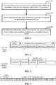
- FIG. 1 is a flowchart of a method for transmitting synchronization indication information according to an exemplary embodiment.
- the method for transmitting synchronization indication information is applied to an access network device such as a base station. As shown in FIG. 1 , the method includes the following operations 101 to 103.
- actual sending position indication information is generated according to the actual offset transmission position.
- the SSB is transmitted at the actual offset transmission position, and the actual sending position indication information is transmitted through a physical broadcast channel block (PBCH).
- PBCH physical broadcast channel block
- a normal transmission position is configured for the SSB in a system, and the normal transmission position may be fixed.
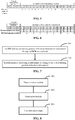
- slot 2 (S2) to slot 5 (S5) are used to transmit SSBO to SSB3, taking four SSBs as an example.
- Positions for multiple SSBs may be continuous or discontinuous. In the embodiment, the positions are continuous, for example. All subsequent time-domain positions starting from slot 6 (S6) may be alternative offset transmission positions.
- the base station determines an SSB to be sent at first, for example, determining that SSBO is to be sent, and detects whether a time-frequency resource on S2 corresponding to SSBO is idle or not. If the time-frequency resource on S2 is idle, SSBO is sent on S2.
- an actual offset transmission position of SSBO is determined in the alternative offset transmission positions, namely the actual offset transmission position is to be selected from S6 and subsequent slots. Then, it is detected whether a time-frequency resource on the actual offset transmission position is idle or not, and if the time-frequency resource at the actual offset transmission position is idle, SSBO is sent at the actual offset transmission position and actual sending position indication information is sent by the base station to UE through the PBCH.
- the UE finds SSBO and receives the actual sending position indication information. According to the actual sending position indication information, the UE knows that the received SSB is SSBO, a slot position of SSBO found may also be known, and synchronization processing is further be completed.
- more possible transmission positions are provided for the SSB, namely the alternative offset transmission positions are added on the basis of the normal transmission position, which provides more transmission opportunities for the SSB.
- actual sending position indication information is also added during alternative transmission, such that the UE can also recognize the SSB when finding the SSB at the alternative offset transmission position.
- the actual sending position indication information when a possible offset transmission position of the SSB in the alternative offset transmission positions is configured to be fixed, includes a slot block sequence number.
- a transmission unit may include five slot blocks, where the first slot block is a normal transmission position, and the last four slot blocks are alternative offset transmission positions. The last four slot blocks are sequentially numbered to obtain slot block sequence numbers 0 to 3 and occupy two bits. If one transmission unit is divided using multiple fixed time-domain units such as subframes or half frames, and the normal transmission position is not limited to the first slot block in the transmission unit and may also be another slot block, then the alternative offset transmission positions include fewer than four slot blocks, and two bits are still enough for representation. If the transmission unit starts from the normal transmission position, for example has a length of 5ms, then the alternative offset transmission positions include four slot blocks, and two bits is still enough for representation.
- a transmission unit has a length of 5ms and includes two slot blocks, the first slot block (slot block 0) is a normal transmission position, and the second slot block (slot block 1) is an alternative offset transmission position. That is, there is only one alternative slot block sequence number, and two bits is still enough for representation.
- Positions of respective SSBs in each slot block are fixed, and it is preset that the UE knows the fixed position of each SSB in the slot block. Therefore, when the slot block sequence number corresponding to the SSB for alternative transmission is notified to the UE, the UE can know which SSB it is and the position of the SSB.
- the slot block sequence number occupies two remaining information bits in the PBCH.
- two bits is enough to represent the slot block sequence number, and thus the slot block sequence number is carried through the two remaining information bits in the PBCH.
- the slot block sequence number occupies two reserved bits A6 and A7 of an SSB sequence number in the PBCH.
- A6 and A7 are two idle reserved bits.
- a solution may be provided by transmitting the slot block sequence number through the two reserved bits.
- any of the alternative offset transmission positions after the normal transmission position in a transmission unit may be used to transmit any SSB. That is, the possible offset transmission position of the SSB in the alternative offset transmission positions is configured to be unfixed. Under this condition, the sequence number of the SSB and the sequence number of the actual offset transmission position in the alternative offset transmission positions may be sent to the UE to notify the UE of an SSB to be sent and the position of the SSB.
- an indication manner is provided for the condition that the possible offset transmission position of the SSB in the alternative offset transmission positions is configured to be unfixed.
- the sequence number of the actual offset transmission position in the alternative offset transmission positions is determined by jointly numbering a system transmission position and the alternative offset transmission positions.
- the sequence number of the actual offset transmission position in the alternative offset transmission positions is determined by sequentially numbering the alternative offset transmission positions.
- the alternative offset transmission positions are independently numbered, as shown in FIG. 5 , and sequence numbers of alternative offset transmission positions corresponding to S4 to S19 are 0 to 16. Indicating bits may be saved.
- sequence number of the actual offset transmission position in the alternative offset transmission positions includes the slot block sequence number and a position number in a slot block.
- the alternative offset transmission position is represented in a manner of combining a slot block sequence number and a position number in a slot block in the embodiment.
- the sequence number of the actual offset transmission position in the alternative offset transmission positions is 00, the first 0 representing the slot block sequence number and the last 0 representing the position number in the slot block.
- the indication manner in the embodiment is similar to the solutions shown in FIG. 2 and FIG. 3 .
- any SSB may be transmitted at each position in the slot block, and the position of the SSB is unfixed.
- the sequence number of the SSB and the sequence number of the actual offset transmission position in the alternative offset transmission positions occupies six remaining information bits that are provided by both the PBCH and a demodulation reference signal (DMRS) sequence.
- DMRS demodulation reference signal
- the sequence number of the SSB and the sequence number of the actual offset transmission position in the alternative offset transmission positions occupy three reserved bits A5, A6 and A7 of the SSB sequence number in the PBCH and occupy lower three bits in the DMRS sequence.
- FIG. 7 is a flowchart of a method for transmitting synchronization indication information according to an exemplary embodiment.
- the method for transmitting synchronization indication information is applied to UE.
- the UE may be a mobile phone, a computer, a digital broadcast terminal, a messaging device, a gaming console, a tablet, a medical device, exercise equipment, a personal digital assistant and the like.
- the method includes the following operations 701 to 702.
- the sensor component 1014 includes one or more sensors configured to provide status assessment in various aspects for the device 1000. For instance, the sensor component 1014 may detect an on/off status of the device 1000 and relative positioning of components, such as a display and small keyboard of the device 1000, and the sensor component 1014 may further detect a change in a position of the device 1000 or a component of the device 1000, presence or absence of contact between the user and the device 1000, orientation or acceleration/deceleration of the device 1000 and a change in temperature of the device 1000.
- the sensor component 1014 may include a proximity sensor configured to detect presence of an object nearby without any physical contact.
- the NFC module may be implemented based on a Radio Frequency Identification (RFID) technology, an Infrared Data Association (IrDA) technology, an Ultra-Wide Band (UWB) technology, a Bluetooth (BT) technology and another technology.
- RFID Radio Frequency Identification
- IrDA Infrared Data Association
- UWB Ultra-Wide Band
- BT Bluetooth
- the device 1000 may be implemented by one or more Application Specific Integrated Circuits (ASICs), Digital Signal Processors (DSPs), Digital Signal Processing Devices (DSPDs), Programmable Logic Devices (PLDs), Field Programmable Gate Arrays (FPGAs), controllers, micro-controllers, microprocessors or other electronic components, and is configured to execute the abovementioned method.
- ASICs Application Specific Integrated Circuits
- DSPs Digital Signal Processors
- DSPDs Digital Signal Processing Devices
- PLDs Programmable Logic Devices
- FPGAs Field Programmable Gate Arrays
- controllers micro-controllers, microprocessors or other electronic components, and is configured to execute the abovementioned method.
- the processor may further be configured as follows: when a possible offset transmission position of the SSB in the alternative offset transmission positions is configured to be fixed, the actual sending position indication information includes a slot block sequence number.
- the processor may further be configured as follows: the slot block sequence number occupies two remaining information bits in the PBCH.
- the processor may further be configured as follows:
- the processor may further be configured as follows: the sequence number of the SSB and the sequence number of the actual offset transmission position in the alternative offset transmission positions occupy three reserved bits A5, A6 and A7 of the SSB sequence number in the PBCH and occupy lower three bits in the DMRS sequence.
- the processor may further be configured as follows: the sequence number of the SSB and the sequence number of the actual offset transmission position in the alternative offset transmission positions also occupy two reserved bits in RMSI or two reserved bits in SSB-FDM.
- the processor may further be configured as follows: when the two reserved bits in the RMSI or the two reserved bits in SSB-FDM are not occupied by the sequence number of the actual offset transmission position in the alternative offset transmission positions, values of the two reserved bits in the RMSI or the two reserved bits in SSB-FDM are preset invalid values.
- the processor may further be configured as follows:
- the processor may further be configured as follows: the actual sending position indication information occupies eight bits.
- the instructions in the storage medium may further include that: the slot block sequence number occupies two remaining information bits in the PBCH.
- the instructions in the storage medium may further include that: when the maximum number of SSBs in a transmission unit is 4 or 8, the slot block sequence number occupies two reserved bits A6 and A7 of an SSB sequence number in the PBCH.
- the instructions in the storage medium may further include that: when the possible offset transmission position of the SSB in the alternative offset transmission positions is configured to be unfixed, the actual sending position indication information includes a sequence number of the SSB and a sequence number of the actual offset transmission position in the alternative offset transmission positions.
- the instructions in the storage medium may further include that: the sequence number of the SSB and the sequence number of the actual offset transmission position in the alternative offset transmission positions occupy six remaining information bits provided by both the PBCH and a DMRS sequence.
- the instructions in the storage medium may further include that: the sequence number of the SSB and the sequence number of the actual offset transmission position in the alternative offset transmission positions occupy three reserved bits A5, A6 and A7 of the SSB sequence number in the PBCH and occupy lower three bits in the DMRS sequence.
- the instructions in the storage medium may further include that: when the two reserved bits in the RMSI or the two reserved bits in SSB-FDM are not occupied by the sequence number of the actual offset transmission position in the alternative offset transmission positions, values of the two reserved bits in the RMSI or the two reserved bits in SSB-FDM are preset invalid values.
- the instructions in the storage medium may further include that:
- the instructions in the storage medium may further include that: the actual sending position indication information occupies eight bits.
Landscapes
- Engineering & Computer Science (AREA)
- Signal Processing (AREA)
- Computer Networks & Wireless Communication (AREA)
- Multimedia (AREA)
- Mobile Radio Communication Systems (AREA)
Abstract
Description
- The present disclosure relates to the technical field of communications, and particularly, to a method and device for transmitting synchronization indication information.
- In related art, a project has recently been set up for research on unlicensed spectrums of 5th-Generation (5G) mobile communication system, and a solution supporting standalone networking of 5G unlicensed cells is proposed. For designing standalone networking of 5G unlicensed spectrums, design of synchronization signal and physical broadcast channel block (SS/PBCH Block, or SSB) is to be considered firstly. However, there is yet no effective solution in the field at present.
- Embodiments of the present disclosure provide a method and device for transmitting synchronization indication information. The technical solutions are implemented as follows.
- According to a first aspect of the embodiments of the present disclosure, a method for transmitting synchronization indication information is provided, which includes that:
- an actual offset transmission position of an SSB to be transmitted is determined in alternative offset transmission positions;
- actual sending position indication information is generated according to the actual offset transmission position; and
- the SSB is transmitted at the actual offset transmission position, and the actual sending position indication information is transmitted through a PBCH.
- The technical solution provided in the embodiments of the present disclosure may have the following beneficial effect. In the embodiments, the actual sending position indication information is added to indicate a position of the SS/PBCH BLOCK in offset transmission, so that User Equipment (UE) performs synchronization processing.
- In an embodiment, when a possible offset transmission position of the SSB in the alternative offset transmission positions is configured to be fixed, the actual sending position indication information may include a slot block sequence number.
- The technical solution provided in the embodiment of the present disclosure may have the following beneficial effect. In the embodiment, the actual sending position indication information is transmitted in the manner of the slot block sequence number, which is applied to the condition that the possible offset transmission position of the SSB in the alternative offset transmission positions has a fixed configuration.
- In an embodiment, the slot block sequence number may occupy two remaining information bits in the PBCH.
- The technical solution provided in the embodiment of the present disclosure may have the following beneficial effect. In the embodiment, a solution of occupying two remaining information bits in the PBCH may be provided.
- In an embodiment, when the maximum number of SSBs in a transmission unit is 4 or 8, the slot block sequence number may occupy two reserved bits A6 and A7 of an SSB sequence number in the PBCH.
- The technical solution provided in the embodiment of the present disclosure may have the following beneficial effect. In the embodiment, a solution of transmitting the slot block sequence number by using the two reserved bits A6 and A7 may be provided.
- In an embodiment, when the possible offset transmission position of the SSB in the alternative offset transmission positions is configured to be unfixed, the actual sending position indication information may include a sequence number of the SSB and a sequence number of the actual offset transmission position in the alternative offset transmission positions.
- The technical solution provided in the embodiment of the present disclosure may have the following beneficial effect. In the embodiment, the actual sending position indication information may also be represented by the sequence number of the SSB and the sequence number of the actual offset transmission position in the alternative offset transmission positions, which is applied to the condition that the possible offset transmission position of the SSB in the alternative offset transmission positions has a unfixed configuration.
- In an embodiment, the sequence number of the actual offset transmission position in the alternative offset transmission positions may be determined by one of: jointly numbering a system transmission position and the alternative offset transmission positions; or
sequentially numbering the alternative offset transmission positions; or
including, in the sequence number of the actual offset transmission position in the alternative offset transmission positions, a slot block sequence number and a position number in a slot block. - The technical solution provided in the embodiment of the present disclosure may have the following beneficial effect. In the embodiment, multiple numbering manners are adopted for the sequence number, which can be applied to multiple application scenarios.
- In an embodiment, the sequence number of the SSB and the sequence number of the actual offset transmission position in the alternative offset transmission positions may occupy six remaining information bits provided by the PBCH and a Demodulation Reference Signal (DMRS) sequence.
- The technical solution provided in the embodiment of the present disclosure may have the following beneficial effect. In the embodiment, a solution of providing the six remaining information bits by both the PBCH and the DMRS sequence to transmit the actual sending position indication information may be provided.
- In an embodiment, the sequence number of the SSB and the sequence number of the actual offset transmission position in the alternative offset transmission positions may occupy three reserved bits A5, A6 and A7 of the SSB sequence number in the PBCH and occupy lower three bits in the DMRS sequence.
- The technical solution provided in the embodiment of the present disclosure may have the following beneficial effect. In the embodiment, a solution that the actual sending position indication information is transmitted through three reserved bits A5, A6 and A7 and the lower three bits in the DMRS sequence may be provided.
- In an embodiment, the sequence number of the SSB and the sequence number of the actual offset transmission position in the alternative offset transmission positions may further occupy two reserved bits in Remaining Minimum System Information (RMSI) or two reserved bits in the SSB transmitted in a frequency division multiplexing mode (SSB-FDM).
- The technical solution provided in the embodiment of the present disclosure may have the following beneficial effect. In the embodiment, for indicating more possible actual offset transmission positions of the SSB, two bits are added, namely the length of the actual sending position indication information is increased.
- In an embodiment, when the two reserved bits in the RMSI or the two reserved bits in the SSB-FDM are not occupied by the sequence number of the actual offset transmission position in the alternative offset transmission positions, the value of the two reserved bits in the RMSI or the two reserved bits in the SSB-FDM may be a preset invalid value.
- The technical solution provided in the embodiment of the present disclosure may have the following beneficial effect. In the embodiment, whether the two extended bits are occupied or not is represented through valid values and invalid values.
- In an embodiment, when the maximum number of SSBs in a transmission unit is 4, the sequence number of the SSB may occupy two reserved bits in the three reserved bits A5, A6 and A7 of the SSB sequence number in the PBCH, and the sequence number of the actual offset transmission position in the alternative offset transmission positions may occupy the remaining one reserved bit in the three reserved bits A5, A6 and A7 and the lower three bits in the DMRS sequence; and
when the maximum number of SSBs in a transmission unit is 8, the sequence number of the SSB may occupy the three reserved bits A5, A6 and A7 of the SSB sequence number in the PBCH, and the sequence number of the actual offset transmission position in the alternative offset transmission positions may occupy the lower three bits in the DMRS sequence, or may further occupy the two reserved bits in the RMSI or the two reserved bits in SSB-FDM. - The technical solution provided in the embodiment of the present disclosure may have the following beneficial effect. In the embodiment, solutions may be provided for the conditions that the maximum number of SSBs in a transmission unit is 4 or 8 respectively.
- In an embodiment, the actual sending position indication information may occupy eight bits.
- The technical solution provided in the embodiment of the present disclosure may have the following beneficial effect. In the embodiment, by considering multiple possible conditions, the actual sending position indication information occupies eight bits, which is compatible with a variety of application scenarios.
- According to a second aspect of the embodiments of the present disclosure, a device for transmitting synchronization indication information is provided, which is be applied at a terminal side and includes that:
- an SSB, and actual sending position indication information transmitted through a PBCH are received; and
- synchronization processing is performed according to the actual sending position indication information.
- According to a third aspect of the embodiments of the present disclosure, a synchronization indication information transmission device is provided, which may be applied to a base station side and include:
- a determination module, configured to determine, in alternative offset transmission positions, an actual offset transmission position of an SSB to be transmitted;
- a generation module, configured to generate actual sending position indication information according to the actual offset transmission position; and
- a transmission module, configured to transmit the SSB at the actual offset transmission position and transmit the actual sending position indication information through a PBCH.
- In an embodiment, when a possible offset transmission position of the SSB in the alternative offset transmission positions is configured to be fixed, the actual sending position indication information may include a slot block sequence number.
- In an embodiment, the slot block sequence number may occupy two remaining information bits in the PBCH.
- In an embodiment, when the maximum number of SSBs in a transmission unit is 4 or 8, the slot block sequence number may occupy two reserved bits A6 and A7 of an SSB sequence number in the PBCH.
- In an embodiment, when the possible offset transmission position of the SSB in the alternative offset transmission positions is configured to be unfixed, the actual sending position indication information may include a sequence number of the SSB and a sequence number of the actual offset transmission position in the alternative offset transmission positions.
- In an embodiment, the sequence number of the actual offset transmission position in the alternative offset transmission positions may be determined by one of: jointly numbering a system transmission position and the alternative offset transmission positions; or
sequentially numbering the alternative offset transmission positions; or
including, in the sequence number of the actual offset transmission position in the alternative offset transmission positions, a slot block sequence number and a position number in a slot block. - In an embodiment, the sequence number of the SSB and the sequence number of the actual offset transmission position in the alternative offset transmission positions may occupy six remaining information bits provided by both the PBCH and a DMRS sequence.
- In an embodiment, the sequence number of the SSB and the sequence number of the actual offset transmission position in the alternative offset transmission positions may occupy three reserved bits A5, A6 and A7 of the SSB sequence number in the PBCH and occupy lower three bits in the DMRS sequence.
- In an embodiment, the sequence number of the SSB and the sequence number of the actual offset transmission position in the alternative offset transmission positions may further occupy two reserved bits in RMSI or two reserved bits in SSB-FDM.
- In an embodiment, when the two reserved bits in the RMSI or the two reserved bits in SSB-FDM are not occupied by the sequence number of the actual offset transmission position in the alternative offset transmission positions, a value of the two reserved bits in the RMSI or the two reserved bits in SSB-FDM may be a preset invalid value.
- In an embodiment, when the maximum number of SSBs in a transmission unit is 4, the sequence number of the SSB may occupy two reserved bits in the three reserved bits A5, A6 and A7 of the SSB sequence number in the PBCH, and the sequence number of the actual offset transmission position in the alternative offset transmission positions may occupy the remaining one reserved bit in A5, A6 and A7 and the lower three bits in the DMRS sequence; and
- when the maximum number of SSBs in a transmission unit is 8, the sequence number of the SSB may occupy the three reserved bits A5, A6 and A7 of the SSB sequence number in the PBCH, and the sequence number of the actual offset transmission position in the alternative offset transmission positions may occupy the lower three bits in the DMRS sequence, or may also occupy the two reserved bits in the RMSI or the two reserved bits in SSB-FDM.
- In an embodiment, the actual sending position indication information may occupy eight bits.
- According to a fourth aspect of the embodiments of the present disclosure, a device for transmitting synchronization indication information is provided, which is applied to a terminal side and includes:
- a receiving module, configured to receive an SSB, and actual sending position indication information transmitted through a PBCH; and
- a synchronization module, configured to perform synchronization processing according to the actual sending position indication information.
- According to a fifth aspect of the embodiments of the present disclosure, a device for transmitting synchronization indication information is provided, which includes:
- a processor; and
- a memory configured to store instructions executable by the processor,
- wherein the processor is configured to:
- determine, in alternative offset transmission positions, an actual offset transmission position of an SSB to be transmitted;
- generate actual sending position indication information according to the actual offset transmission position; and
- transmit the SSB at the actual offset transmission position and transmit the actual sending position indication information through a PBCH.
- According to a sixth aspect of the embodiments of the present disclosure, a method and device for transmitting synchronization indication information is provided, which includes:
- a processor; and
- a memory configured to store instructions executable by the processor,
- wherein the processor is configured to:
- receive an SSB, and actual sending position indication information transmitted through a PBCH; and
- perform synchronization processing according to the actual sending position indication information.
- According to a seventh aspect of the embodiments of the present disclosure, a computer-readable storage medium is provided, in which computer instructions are stored, the instructions, when being executed by a processor, cause to implement the method applied to a base station side.
- According to an eighth aspect of the embodiments of the present disclosure, a computer-readable storage medium is provided, in which computer instructions are stored, the instructions, when being executed by a processor, cause to implement the method applied to a UE side.
- It is to be understood that the above general descriptions and detailed description below are only exemplary and explanatory and not intended to limit the present disclosure.
- The accompanying drawings, which are incorporated in and constitute a part of this specification, illustrate embodiments consistent with the present disclosure and, together with the description, serve to explain the principles of the present disclosure.
-
FIG. 1 is a flowchart of a method for transmitting synchronization indication information according to an exemplary embodiment. -
FIG. 2 is a schematic diagram illustrating a slot structure according to an exemplary embodiment. -
FIG. 3 is a schematic diagram illustrating a slot structure according to an exemplary embodiment. -
FIG. 4 is a schematic diagram illustrating a slot structure according to an exemplary embodiment. -
FIG. 5 is a schematic diagram illustrating a slot structure according to an exemplary embodiment. -
FIG. 6 is a schematic diagram illustrating a slot structure according to an exemplary embodiment. -
FIG. 7 is a flowchart of a method for transmitting synchronization indication information according to an exemplary embodiment. -
FIG. 8 is a block diagram of a device for transmitting synchronization indication information according to an exemplary embodiment. -
FIG. 9 is a block diagram of a device for transmitting synchronization indication information according to an exemplary embodiment. -
FIG. 10 is a block diagram of a device for transmitting synchronization indication information according to an exemplary embodiment. -
FIG. 11 is a block diagram of a device for transmitting synchronization indication information according to an exemplary embodiment. - Reference will now be made in detail to exemplary embodiments, examples of which are illustrated in the accompanying drawings. The following description refers to the accompanying drawings in which the same numbers in different drawings represent the same or similar elements unless otherwise represented. The implementations set forth in the following description of exemplary embodiments do not represent all implementations consistent with the present disclosure. Instead, they are merely examples of apparatuses and methods consistent with aspects related to the present disclosure as recited in the appended claims.
- In related art, a project has recently been set up for research on unlicensed spectrums of 5G mobile communication system, and a solution supporting standalone networking of 5G unlicensed cells is proposed. For designing standalone networking of 5G unlicensed spectrums, design about an SS/PBCH Block (SSB) is to be considered firstly. For an unlicensed spectrum, it may be necessary to follow a Listen Before Talk (LBT) principle. When an SSB needs to be transmitted, under the LBT principle, the SSB may not be transmitted at a fixedly configured position (normal transmission position) of a system because a time-frequency resource is occupied. In such case, the SSB may be tried to be sent again at an alternative offset transmission position allowed by the system, so that the UE timely synchronizes with a network side. At the same time of sending the SSB at the alternative offset transmission position, it is also necessary to notify the UE what the alternative offset transmission position is and which SSB is to be sent. For the problem, there is yet no effective solution in the field. If the time-frequency resource of the normal transmission position is not occupied, the SSB is transmitted at the normal transmission position.
- For solving the problem, actual sending position indication information is added in the embodiment to notify UE of an actual offset transmission position and a specific SSB that is to be sent.
-
FIG. 1 is a flowchart of a method for transmitting synchronization indication information according to an exemplary embodiment. The method for transmitting synchronization indication information is applied to an access network device such as a base station. As shown inFIG. 1 , the method includes the followingoperations 101 to 103. - In
operation 101, an actual offset transmission position of an SSB to be transmitted is determined in alternative offset transmission positions. - In
operation 102, actual sending position indication information is generated according to the actual offset transmission position. - In
operation 103, the SSB is transmitted at the actual offset transmission position, and the actual sending position indication information is transmitted through a physical broadcast channel block (PBCH). - In the embodiment, a normal transmission position is configured for the SSB in a system, and the normal transmission position may be fixed. For example, slot 2 (S2) to slot 5 (S5) are used to transmit SSBO to SSB3, taking four SSBs as an example. Positions for multiple SSBs may be continuous or discontinuous. In the embodiment, the positions are continuous, for example. All subsequent time-domain positions starting from slot 6 (S6) may be alternative offset transmission positions. The base station determines an SSB to be sent at first, for example, determining that SSBO is to be sent, and detects whether a time-frequency resource on S2 corresponding to SSBO is idle or not. If the time-frequency resource on S2 is idle, SSBO is sent on S2. If the time-frequency resource on S2 is not idle, an actual offset transmission position of SSBO is determined in the alternative offset transmission positions, namely the actual offset transmission position is to be selected from S6 and subsequent slots. Then, it is detected whether a time-frequency resource on the actual offset transmission position is idle or not, and if the time-frequency resource at the actual offset transmission position is idle, SSBO is sent at the actual offset transmission position and actual sending position indication information is sent by the base station to UE through the PBCH.
- The UE finds SSBO and receives the actual sending position indication information. According to the actual sending position indication information, the UE knows that the received SSB is SSBO, a slot position of SSBO found may also be known, and synchronization processing is further be completed.
- According to the embodiment, more possible transmission positions are provided for the SSB, namely the alternative offset transmission positions are added on the basis of the normal transmission position, which provides more transmission opportunities for the SSB. In addition, actual sending position indication information is also added during alternative transmission, such that the UE can also recognize the SSB when finding the SSB at the alternative offset transmission position.
- In an embodiment, when a possible offset transmission position of the SSB in the alternative offset transmission positions is configured to be fixed, the actual sending position indication information includes a slot block sequence number.
- In the embodiment, fixed positions are configured for each SSB during normal transmission and alternative transmission. As shown in
FIG. 2 , the maximum number L of SSBs in a transmission unit is specified in the system, and the number of SSBs that are actually transmitted may be less than or equal to L. In the embodiment, a time-domain length occupied by the number of L SSBs is called a slot block. For example, L=4, and slot positions of SSBs are continuous. For example, if SSBO to SSB3 correspond to S2 to S5, then S2 to S5 form a slot block. Slot blocks may be continuous or discontinuous. In the embodiment, slot blocks at alternative offset transmission positions in a transmission unit are sequentially numbered to obtain slot block sequence numbers. - For example, L=4, a transmission unit may include five slot blocks, where the first slot block is a normal transmission position, and the last four slot blocks are alternative offset transmission positions. The last four slot blocks are sequentially numbered to obtain slot
block sequence numbers 0 to 3 and occupy two bits. If one transmission unit is divided using multiple fixed time-domain units such as subframes or half frames, and the normal transmission position is not limited to the first slot block in the transmission unit and may also be another slot block, then the alternative offset transmission positions include fewer than four slot blocks, and two bits are still enough for representation. If the transmission unit starts from the normal transmission position, for example has a length of 5ms, then the alternative offset transmission positions include four slot blocks, and two bits is still enough for representation. - As shown in
FIG. 3 , for example, L=8, a transmission unit has a length of 5ms and includes two slot blocks, the first slot block (slot block 0) is a normal transmission position, and the second slot block (slot block 1) is an alternative offset transmission position. That is, there is only one alternative slot block sequence number, and two bits is still enough for representation. - Positions of respective SSBs in each slot block are fixed, and it is preset that the UE knows the fixed position of each SSB in the slot block. Therefore, when the slot block sequence number corresponding to the SSB for alternative transmission is notified to the UE, the UE can know which SSB it is and the position of the SSB.
- In an embodiment, the slot block sequence number occupies two remaining information bits in the PBCH.
- In the embodiment, two bits is enough to represent the slot block sequence number, and thus the slot block sequence number is carried through the two remaining information bits in the PBCH.
- In an embodiment, when the maximum number of SSBs in one transmission unit is 4 or 8, the slot block sequence number occupies two reserved bits A6 and A7 of an SSB sequence number in the PBCH.
- In the related art, when L=4 or 8, A6 and A7 are two idle reserved bits. In the embodiment, a solution may be provided by transmitting the slot block sequence number through the two reserved bits.
- In an embodiment, when the possible offset transmission position of the SSB in the alternative offset transmission positions is configured to be unfixed, the actual sending position indication information includes a sequence number of the SSB and a sequence number of the actual offset transmission position in the alternative offset transmission positions.
- In the embodiment, any of the alternative offset transmission positions after the normal transmission position in a transmission unit may be used to transmit any SSB. That is, the possible offset transmission position of the SSB in the alternative offset transmission positions is configured to be unfixed. Under this condition, the sequence number of the SSB and the sequence number of the actual offset transmission position in the alternative offset transmission positions may be sent to the UE to notify the UE of an SSB to be sent and the position of the SSB.
- In the embodiment, an indication manner is provided for the condition that the possible offset transmission position of the SSB in the alternative offset transmission positions is configured to be unfixed.
- In an example, the sequence number of the actual offset transmission position in the alternative offset transmission positions is determined by jointly numbering a system transmission position and the alternative offset transmission positions.
- In the embodiment, the system transmission position is the normal transmission position. For example, if a transmission unit includes 20 slots and L=4, then slot sequence numbers in the transmission unit are from S0 to S19. S0 to S3 are normal transmission positions, and S4 to S19 are all alternative offset transmission positions, as shown in
FIG. 4 . - In an example, the sequence number of the actual offset transmission position in the alternative offset transmission positions is determined by sequentially numbering the alternative offset transmission positions.
- In the example, the alternative offset transmission positions are independently numbered, as shown in
FIG. 5 , and sequence numbers of alternative offset transmission positions corresponding to S4 to S19 are 0 to 16. Indicating bits may be saved. - In an example the sequence number of the actual offset transmission position in the alternative offset transmission positions includes the slot block sequence number and a position number in a slot block.
- As shown in
FIG. 6 , the alternative offset transmission position is represented in a manner of combining a slot block sequence number and a position number in a slot block in the embodiment. For example, during alternative transmission of the SSB on S4, the sequence number of the actual offset transmission position in the alternative offset transmission positions is 00, the first 0 representing the slot block sequence number and the last 0 representing the position number in the slot block. The indication manner in the embodiment is similar to the solutions shown inFIG. 2 and FIG. 3 . However, any SSB may be transmitted at each position in the slot block, and the position of the SSB is unfixed. - In the embodiment, multiple numbering manners are provided. Accordingly, multiple indication manners are correspondingly provided, which can be applied to a variety of application scenarios. When the indication manners are adopted, few bits are occupied, and network resources occupied are saved as much as possible.
- In an embodiment, the sequence number of the SSB and the sequence number of the actual offset transmission position in the alternative offset transmission positions occupies six remaining information bits that are provided by both the PBCH and a demodulation reference signal (DMRS) sequence.
- It can be seen from the foregoing introductions that the sequence number of the SSB and the sequence number of the actual offset transmission position in the alternative offset transmission positions occupying six bits may cover most conditions. Therefore, a solution of occupying the remaining information bits, totally six bits, in the PBCH and the DMRS sequence may be provided in the embodiment.
- In an embodiment, the sequence number of the SSB and the sequence number of the actual offset transmission position in the alternative offset transmission positions occupy three reserved bits A5, A6 and A7 of the SSB sequence number in the PBCH and occupy lower three bits in the DMRS sequence.
- Since it is necessary to send the sequence number of the SSB and the sequence number of the actual offset transmission position in the alternative offset transmission positions to the UE, more indicating bits are required. In the embodiment, a solution of adopting the three reserved bits A5, A6 and A7 and occupying the lower three bits in the DMRS sequence, totally six bits, may be provided.
- For the solution shown in
FIG. 4 , for example, L=4, one transmission unit includes 20 slots, the sequence number of the SSB occupies two bits, and thesequence numbers 4 to 19 of the alternative offset transmission positions need to occupy five bits. However, in the embodiment, four bits are provided for the sequence numbers of the alternative offset transmission positions, and thus, some slot positions may need to be discarded, for example, the four slot positions S 16 to S19 are discarded. - For example, L=8, the sequence number of the SSB occupies three bits, and even though the alternative offset transmission positions are independently numbered, the sequence numbers (0 to 11) of the alternative offset transmission positions needs to occupy four bits. However, in the embodiment, three bits are provided for the sequence numbers of the alternative offset transmission positions, and thus some slot positions may need to be discarded.
- In an embodiment, the sequence number of the SSB and the sequence number of the actual offset transmission position in the alternative offset transmission positions also occupy two reserved bits in remaining minimum system information (RMSI) or two reserved bits in the SSB transmitted in a frequency division multiplexing mode, referred to herein as the SSB-FDM.
- In the embodiment, two bits are further added. The two reserved bits in the RMSI or the two reserved bits in the SSB-FDM may be adopted so that more indicating bits are provided for the alternative offset transmission positions, which is equivalent to that more alternative offset transmission positions are provided.
- In an embodiment, when the two reserved bits in the RMSI or the two reserved bits in the SSB-FDM are not occupied by the sequence number of the actual offset transmission position in the alternative offset transmission positions, values of the two reserved bits in the RMSI or the two reserved bits in the SSB-FDM are preset invalid values.
- As described above, if the solution shown in
FIG. 5 is adopted, the sequence number of the SSB and the sequence number of the actual offset transmission position in the alternative offset transmission positions may be indicated using six bits. In such case, the two reserved bits in the RMSI or the two reserved bits in the SSB-FDM are idle and may be configured to be invalid values such as 11 to represent that the bits are idle and not adopted. - If the solution shown in
FIG. 4 is adopted, eight bits are required to indicate the sequence number of the SSB and the sequence number of the actual offset transmission position in the alternative offset transmission positions. In such case, corresponding valid values such as other values except 11 may be adopted for the two reserved bits in the RMSI or the two reserved bits in the SSB-FDM. - In an embodiment, when the maximum number of SSBs in a transmission unit is 4, the sequence number of the SSB occupies two reserved bits in the three reserved bits A5, A6 and A7 of the SSB sequence number in the PBCH, and the sequence number of the actual offset transmission position in the alternative offset transmission positions occupies the remaining one reserved bit in A5, A6 and A7 and the lower three bits in the DMRS sequence.
- When the maximum number of SSBs in a transmission unit is 8, the sequence number of the SSB occupies the three reserved bits A5, A6 and A7 of the SSB sequence number in the PBCH, and the sequence number of the actual offset transmission position in the alternative offset transmission positions occupies the lower three bits in the DMRS sequence, or also occupies the two reserved bits in the RMSI or the two reserved bits in the SSB-FDM.
- In the embodiment, the sequence number of the SSB and a specific position of the sequence number of the actual offset transmission position in the alternative offset transmission positions are provided, and a detailed solution may be also provided.
- In an embodiment, the actual sending position indication information occupies eight bits.
- In the embodiment, the actual sending position indication information occupies eight bits under various conditions, which is compatible with the embodiments as described above.
- An implementation process on the base station side is introduced above. Correspondingly, a UE side is required to adopt a solution consistent with that of the base station side. An implementation process on the UE side is introduced below.
-
FIG. 7 is a flowchart of a method for transmitting synchronization indication information according to an exemplary embodiment. The method for transmitting synchronization indication information is applied to UE. The UE may be a mobile phone, a computer, a digital broadcast terminal, a messaging device, a gaming console, a tablet, a medical device, exercise equipment, a personal digital assistant and the like. As shown inFIG. 7 , the method includes the followingoperations 701 to 702. - In
operation 701, an SSB and actual sending position indication information transmitted through a PBCH are received by the UE. - In
operation 702, synchronization processing is performed by the UE according to the actual sending position indication information. - In the embodiment, the UE can receive the SSB and the corresponding actual sending position indication information, and learn about the specific SSB that is received and a position of the SSB by parsing the actual sending position indication information, and thus to implement synchronization processing.
- Multiple manners for indicating the actual sending position indication information are provided above the base station side, and corresponding parsing manners are may be configured on the UE side, which will not elaborated herein.
- The above embodiments may be flexibly combined according to a practical requirement.
- The below is a device embodiment of the present disclosure, which may be configured to execute the method embodiments of the present disclosure.
-
FIG. 8 is a block diagram of a device for transmitting synchronization indication information according to an exemplary embodiment. The device may be implemented into part or all of an electronic device through software, or hardware, or a combination thereof. The device for transmitting synchronization indication information is applied to a base station and includes adetermination module 801, ageneration module 802 and atransmission module 803 referring toFIG. 8 . - The
determination module 801 is configured to determine an actual offset transmission position of a to-be-transmitted SSB in alternative offset transmission positions. - The
generation module 802 is configured to generate actual sending position indication information according to the actual offset transmission position. - The
transmission module 803 is configured to transmit the SSB at the actual offset transmission position and transmit the actual sending position indication information through a PBCH. - In an embodiment, when a possible offset transmission position of the SSB in the alternative offset transmission positions is configured to be fixed, the actual sending position indication information includes a slot block sequence number.
- In an embodiment, the slot block sequence number occupies two remaining information bits in the PBCH.
- In an embodiment, when the maximum number of SSBs in a transmission unit is 4 or 8, the slot block sequence number occupies two reserved bits A6 and A7 of an SSB sequence number in the PBCH.
- In an embodiment, when the possible offset transmission position of the SSB in the alternative offset transmission positions is configured to be unfixed, the actual sending position indication information includes a sequence number of the SSB and a sequence number of the actual offset transmission position in the alternative offset transmission positions.
- In an embodiment, the sequence number of the actual offset transmission position in the alternative offset transmission positions is determined by jointly numbering a system transmission position and the alternative offset transmission positions; or
the sequence number of the actual offset transmission position in the alternative offset transmission positions is determined by sequentially numbering the alternative offset transmission positions; or
the sequence number of the actual offset transmission position in the alternative offset transmission positions includes the slot block sequence number and a position number in a slot block. - In an embodiment, the sequence number of the SSB and the sequence number of the actual offset transmission position in the alternative offset transmission positions occupy six remaining information bits provided by both the PBCH and a DMRS sequence.
- In an embodiment, the sequence number of the SSB and the sequence number of the actual offset transmission position in the alternative offset transmission positions occupy three reserved bits A5, A6 and A7 of the SSB sequence number in the PBCH and occupy lower three bits in the DMRS sequence.
- In an embodiment, the sequence number of the SSB and the sequence number of the actual offset transmission position in the alternative offset transmission positions also occupy two reserved bits in RMSI or two reserved bits in SSB-FDM.
- In an embodiment, when the two reserved bits in the RMSI or the two reserved bits in the SSB-FDM are not occupied by the sequence number of the actual offset transmission position in the alternative offset transmission positions, values of the two reserved bits in the RMSI or the two reserved bits in the SSB-FDM are preset invalid values.
- In an embodiment, when the maximum number of SSBs in a transmission unit is 4, the sequence number of the SSB occupies two reserved bits in the three reserved bits A5, A6 and A7 of the SSB sequence number in the PBCH, and the sequence number of the actual offset transmission position in the alternative offset transmission positions may occupies the remaining reserved bit in A5, A6 and A7 and the lower three bits in the DMRS sequence; and
when the maximum number of SSBs in a transmission unit is 8, the sequence number of the SSB occupies the three reserved bits A5, A6 and A7 of the SSB sequence number in the PBCH, and the sequence number of the actual offset transmission position in the alternative offset transmission positions occupies the lower three bits in the DMRS sequence, or also occupies the two reserved bits in the RMSI or the two reserved bits in SSB-FDM. - In an embodiment, the actual sending position indication information occupies eight bits.
-
FIG. 9 is a block diagram of a device for transmitting synchronization indication information according to an exemplary embodiment. The device may be implemented into part or all of an electronic device through software, or hardware or a combination thereof. The device for transmitting synchronization indication information is applied to a UE side, and includes a receivingmodule 901 and asynchronization module 902 referring toFIG. 9 . - The receiving
module 901 is configured to receive an SSB and actual sending position indication information that is transmitted through a PBCH. - The
synchronization module 902 is configured to perform synchronization processing according to the actual sending position indication information. - Parts that are not specifically described in the device embodiments may refer to the method embodiments.
- For the device in the above embodiments, the specific manner for the operations executed by various modules have been described in detail in the embodiments related to the method, and is not elaborated herein.
-
FIG. 10 is a block diagram of a device for transmitting synchronization indication information according to an exemplary embodiment. For example, thedevice 1000 may be UE, such as a mobile phone, a computer, a digital broadcast terminal, a messaging device, a gaming console, a tablet, a medical device, exercise equipment, a personal digital assistant and the like. - The
device 1000 may include one or more of the following components: aprocessing component 1002, amemory 1004, apower component 1006, amultimedia component 1008, anaudio component 1010, an Input/Output (I/O)interface 1010, asensor component 1014, and acommunication component 1016. - The
processing component 1002 typically controls overall operations of thedevice 1000, such as the operations associated with display, telephone calls, data communications, camera operations, and recording operations. Theprocessing component 1002 may include one ormore processors 1020 to execute instructions to perform all or part of the steps in the abovementioned method. Moreover, theprocessing component 1002 may include one or more modules which facilitate interaction between theprocessing component 1002 and the other components. For instance, theprocessing component 1002 may include a multimedia module to facilitate interaction between themultimedia component 1008 and theprocessing component 1002. - The
memory 1004 is configured to store various types of data to support the operation of thedevice 1000. Examples of such data include instructions for any applications or methods operated on thedevice 1000, contact data, phonebook data, messages, pictures, video, etc. Thememory 1004 may be implemented by any type of volatile or non-volatile memory devices, or a combination thereof, such as a Static Random Access Memory (SRAM), an Electrically Erasable Programmable Read-Only Memory (EEPROM), an Erasable Programmable Read-Only Memory (EPROM), a Programmable Read-Only Memory (PROM), a Read-Only Memory (ROM), a magnetic memory, a flash memory, and a magnetic or optical disk. - The
power component 1006 provides power for various components of thedevice 1000. Thepower component 1006 may include a power management system, one or more power supplies, and other components associated with generation, management and distribution of power for thedevice 1000. - The
multimedia component 1008 includes a screen providing an output interface between thedevice 1000 and a user. In some embodiments, the screen may include a Liquid Crystal Display (LCD) and a Touch Panel (TP). If the screen includes the TP, the screen may be implemented as a touch screen to receive an input signal from the user. The touch panel includes one or more touch sensors to sense touches, swipes and gestures on the touch panel. The touch sensors may not only sense a boundary of a touch or swipe action but also detect a duration and pressure associated with the touch or swipe action. In some embodiments, themultimedia component 1008 includes a front camera and/or a rear camera. The front camera and/or the rear camera may receive external multimedia data when thedevice 1000 is in an operation mode, such as a photographing mode or a video mode. Each of the front camera and the rear camera may be a fixed optical lens system or have focusing and optical zooming capabilities. - The
audio component 1010 is configured to output and/or input an audio signal. For example, theaudio component 1010 includes a Microphone (MIC), and the MIC is configured to receive an external audio signal when thedevice 1000 is in the operation mode, such as a call mode, a recording mode and a voice recognition mode. The received audio signal may further be stored in thememory 1004 or sent through thecommunication component 1016. In some embodiments, theaudio component 1010 further includes a speaker configured to output the audio signal. - The I/
O interface 1010 provides an interface between theprocessing component 1002 and a peripheral interface module, and the peripheral interface module may be a keyboard, a click wheel, a button and the like. The button may include, but not limited to: a home button, a volume button, a starting button and a locking button. - The
sensor component 1014 includes one or more sensors configured to provide status assessment in various aspects for thedevice 1000. For instance, thesensor component 1014 may detect an on/off status of thedevice 1000 and relative positioning of components, such as a display and small keyboard of thedevice 1000, and thesensor component 1014 may further detect a change in a position of thedevice 1000 or a component of thedevice 1000, presence or absence of contact between the user and thedevice 1000, orientation or acceleration/deceleration of thedevice 1000 and a change in temperature of thedevice 1000. Thesensor component 1014 may include a proximity sensor configured to detect presence of an object nearby without any physical contact. Thesensor component 1014 may also include a light sensor, such as a Complementary Metal Oxide Semiconductor (CMOS) or Charge Coupled Device (CCD) image sensor, configured for use in an imaging application. In some embodiments, thesensor component 1014 may also include an acceleration sensor, a gyroscope sensor, a magnetic sensor, a pressure sensor or a temperature sensor. - The
communication component 1016 is configured to facilitate wired or wireless communication between thedevice 1000 and another device. Thedevice 1000 may access a communication-standard-based wireless network, such as a Wireless Fidelity (WiFi) network, a 2nd-Generation (2G) or 3rd-Generation (3G) network or a combination thereof. In an exemplary embodiment, thecommunication component 1016 receives a broadcast signal or broadcast associated information from an external broadcast management system through a broadcast channel. In an exemplary embodiment, thecommunication component 1016 further includes a Near Field Communication (NFC) module to facilitate short-range communication. For example, the NFC module may be implemented based on a Radio Frequency Identification (RFID) technology, an Infrared Data Association (IrDA) technology, an Ultra-Wide Band (UWB) technology, a Bluetooth (BT) technology and another technology. - In an exemplary embodiment, the
device 1000 may be implemented by one or more Application Specific Integrated Circuits (ASICs), Digital Signal Processors (DSPs), Digital Signal Processing Devices (DSPDs), Programmable Logic Devices (PLDs), Field Programmable Gate Arrays (FPGAs), controllers, micro-controllers, microprocessors or other electronic components, and is configured to execute the abovementioned method. - In an exemplary embodiment, there is also provided a non-transitory computer-readable storage medium including an instruction, such as the
memory 1004 including an instruction, and the instruction may be executed by theprocessor 1020 of thedevice 1000 to implement the abovementioned method. For example, the non-transitory computer-readable storage medium may be a ROM, a Random Access Memory (RAM), a Compact Disc Read-Only Memory (CD-ROM), a magnetic tape, a floppy disc, an optical data storage device and the like. - In an exemplary embodiment, a device for transmitting synchronization indication information is provided, which includes:
- a processor; and
- a memory configured to store instructions executable by the processor,
- where the processor is configured to:
- receive an SSB and actual sending position indication information that is transmitted through a PBCH; and
- perform synchronization processing according to the actual sending position indication information.
- There is also provide a computer-readable storage medium, where instructions in the storage medium, when being executed by a processor of a device, enable the device to perform the method for transmitting synchronization indication information, the method including that:
- an SSB and actual sending position indication information transmitted through a PBCH are received; and
- synchronization processing is performed according to the actual sending position indication information.
-
FIG. 11 is a block diagram of adevice 1100 for data synchronization according to an exemplary embodiment. For example, thedevice 1100 may be provided as a computer. Referring toFIG. 11 , thedevice 1100 includes aprocessing component 1122 which further including one or more processors, and a memory resource represented by amemory 1132, configured to store instructions executable by theprocessing component 1122, for example, an application program. The application program stored in thememory 1132 may include one or more than one module of which each corresponds to a set of instructions. In addition, theprocessing component 1122 is configured to execute the instructions to execute the method for data synchronization. - The
device 1100 may further include apower component 1126 configured to execute power management of thedevice 1100, a wired orwireless network interface 1150 configured to connect thedevice 1100 to a network and an I/O interface 1158. Thedevice 1100 may be operated based on an operating system stored in thememory 1132, for example, Windows ServerTM, Mac OS XTM, UnixTM, LinuxTM, FreeBSDTM or the like. - In an exemplary embodiment, a device for transmitting synchronization indication information is provided, which includes:
- a processor; and
- a memory configured to store instructions executable by the processor,
- where the processor is configured to:
- determine an actual offset transmission position of a to-be-transmitted SSB in alternative offset transmission positions;
- generate actual sending position indication information according to the actual offset transmission position; and
- transmit the SSB at the actual offset transmission position and transmit the actual sending position indication information through a PBCH.
- The processor may further be configured as follows:
when a possible offset transmission position of the SSB in the alternative offset transmission positions is configured to be fixed, the actual sending position indication information includes a slot block sequence number. - The processor may further be configured as follows:
the slot block sequence number occupies two remaining information bits in the PBCH. - The processor may further be configured as follows:
when the maximum number of SSBs in a transmission unit is 4 or 8, the slot block sequence number occupies two reserved bits A6 and A7 of an SSB sequence number in the PBCH. - The processor may further be configured as follows:
when the possible offset transmission position of the SSB in the alternative offset transmission positions is configured to be unfixed, the actual sending position indication information includes a sequence number of the SSB and a sequence number of the actual offset transmission position in the alternative offset transmission positions. - The processor may further be configured as follows:
- the sequence number of the actual offset transmission position in the alternative offset transmission positions is determined by jointly numbering a system transmission position and the alternative offset transmission positions; or
- the sequence number of the actual offset transmission position in the alternative offset transmission positions is determined by sequentially numbering the alternative offset transmission positions; or
- the sequence number of the actual offset transmission position in the alternative offset transmission positions includes the slot block sequence number and a position number in a slot block.
- The processor may further be configured as follows:
the sequence number of the SSB and the sequence number of the actual offset transmission position in the alternative offset transmission positions occupy six remaining information bits provided by both the PBCH and a DMRS sequence. - The processor may further be configured as follows:
the sequence number of the SSB and the sequence number of the actual offset transmission position in the alternative offset transmission positions occupy three reserved bits A5, A6 and A7 of the SSB sequence number in the PBCH and occupy lower three bits in the DMRS sequence. - The processor may further be configured as follows:
the sequence number of the SSB and the sequence number of the actual offset transmission position in the alternative offset transmission positions also occupy two reserved bits in RMSI or two reserved bits in SSB-FDM. - The processor may further be configured as follows:
when the two reserved bits in the RMSI or the two reserved bits in SSB-FDM are not occupied by the sequence number of the actual offset transmission position in the alternative offset transmission positions, values of the two reserved bits in the RMSI or the two reserved bits in SSB-FDM are preset invalid values. - The processor may further be configured as follows:
- when the maximum number of SSBs in a transmission unit is 4, the sequence number of the SSB occupies two reserved bits in the three reserved bits A5, A6 and A7 of the SSB sequence number in the PBCH, and the sequence number of the actual offset transmission position in the alternative offset transmission positions occupies the remaining reserved bit in A5, A6 and A7 and the lower three bits in the DMRS sequence; and
- when the maximum number of SSBs in a transmission unit is 8, the sequence number of the SSB occupies the three reserved bits A5, A6 and A7 of the SSB sequence number in the PBCH, and the sequence number of the actual offset transmission position in the alternative offset transmission positions occupies the lower three bits in the DMRS sequence, or also occupies the two reserved bits in the RMSI or the two reserved bits in SSB-FDM.
- The processor may further be configured as follows:
the actual sending position indication information occupies eight bits. - According to a computer-readable storage medium, instructions in the storage medium are executed by a processor of a device to enable the device to execute the method for transmitting synchronization indication information, the method including that:
- an actual offset transmission position of an SSB to be transmitted is determined in alternative offset transmission positions;
- actual sending position indication information is generated according to the actual offset transmission position; and
- the SSB at the actual offset transmission position is transmitted, and the actual sending position indication information is transmitted through a PBCH.
- The instructions in the storage medium may further include that:
when a possible offset transmission position of the SSB in the alternative offset transmission positions is configured to be fixed, the actual sending position indication information includes a slot block sequence number. - The instructions in the storage medium may further include that:
the slot block sequence number occupies two remaining information bits in the PBCH. - The instructions in the storage medium may further include that:
when the maximum number of SSBs in a transmission unit is 4 or 8, the slot block sequence number occupies two reserved bits A6 and A7 of an SSB sequence number in the PBCH. - The instructions in the storage medium may further include that:
when the possible offset transmission position of the SSB in the alternative offset transmission positions is configured to be unfixed, the actual sending position indication information includes a sequence number of the SSB and a sequence number of the actual offset transmission position in the alternative offset transmission positions. - The instructions in the storage medium may further include that:
- the sequence number of the actual offset transmission position in the alternative offset transmission positions is determined by jointly numbering a system transmission position and the alternative offset transmission positions; or
- the sequence number of the actual offset transmission position in the alternative offset transmission positions is determined by sequentially numbering the alternative offset transmission positions; or
- the sequence number of the actual offset transmission position in the alternative offset transmission positions includes the slot block sequence number and a position number in a slot block.
- The instructions in the storage medium may further include that:
the sequence number of the SSB and the sequence number of the actual offset transmission position in the alternative offset transmission positions occupy six remaining information bits provided by both the PBCH and a DMRS sequence. - The instructions in the storage medium may further include that:
the sequence number of the SSB and the sequence number of the actual offset transmission position in the alternative offset transmission positions occupy three reserved bits A5, A6 and A7 of the SSB sequence number in the PBCH and occupy lower three bits in the DMRS sequence. - The instructions in the storage medium may further include that:
the sequence number of the SSB and the sequence number of the actual offset transmission position in the alternative offset transmission positions also occupy two reserved bits in RMSI or two reserved bits in SSB-FDM. - The instructions in the storage medium may further include that:
when the two reserved bits in the RMSI or the two reserved bits in SSB-FDM are not occupied by the sequence number of the actual offset transmission position in the alternative offset transmission positions, values of the two reserved bits in the RMSI or the two reserved bits in SSB-FDM are preset invalid values. - The instructions in the storage medium may further include that:
- when the maximum number of SSBs in a transmission unit is 4, the sequence number of the SSB occupies two reserved bits in the three reserved bits A5, A6 and A7 of the SSB sequence number in the PBCH, and the sequence number of the actual offset transmission position in the alternative offset transmission positions occupies the remaining reserved bit in A5, A6 and A7 and the lower three bits in the DMRS sequence; and
- when the maximum number of SSBs in a transmission unit is 8, the sequence number of the SSB occupies the three reserved bits A5, A6 and A7 of the SSB sequence number in the PBCH, and the sequence number of the actual offset transmission position in the alternative offset transmission positions occupies the lower three bits in the DMRS sequence, or also occupies the two reserved bits in the RMSI or the two reserved bits in SSB-FDM.
- The instructions in the storage medium may further include that:
the actual sending position indication information occupies eight bits. - Other implementation solutions of the present disclosure will be apparent to those skilled in the art from consideration of the specification and practice of the present disclosure. This application is intended to cover any variations, uses, or adaptations of the present disclosure following the general principles thereof and including such departures from the present disclosure as come within known or customary practice in the art. It is intended that the specification and examples be considered as exemplary only, with a true scope and spirit of the present disclosure being indicated by the following claims.
- It will be appreciated that the present disclosure is not limited to the exact construction that has been described above and illustrated in the accompanying drawings, and that various modifications and changes may be made without departing from the scope thereof. It is intended that the scope of the present disclosure only be limited by the appended claims.
Claims (30)
- A method for transmitting synchronization indication information, the method being applied to a based station and comprising:determining, in alternative offset transmission positions, an actual offset transmission position of a synchronization signal and physical broadcast channel block (SSB) to be transmitted;generating actual sending position indication information according to the actual offset transmission position; andtransmitting the SSB at the actual offset transmission position, and transmitting the actual sending position indication information through a physical broadcast channel (PBCH).
- The method of claim 1, wherein, when a possible offset transmission position of the SSB in the alternative offset transmission positions is configured to be fixed, the actual sending position indication information comprises a slot block sequence number.
- The method of claim 2, wherein the slot block sequence number occupies two remaining information bits in the PBCH.
- The method of claim 3, wherein, when a maximum number of SSBs in a transmission unit is 4 or 8, the slot block sequence number occupies two reserved bits A6 and A7 of an SSB sequence number in the PBCH.
- The method of claim 1, wherein, when a possible offset transmission position of the SSB in the alternative offset transmission positions is configured to be unfixed, the actual sending position indication information comprises a sequence number of the SSB and a sequence number of the actual offset transmission position in the alternative offset transmission positions.
- The method of claim 5, wherein the sequence number of the actual offset transmission position in the alternative offset transmission positions is determined by one of:jointly numbering a system transmission position and the alternative offset transmission positions;sequentially numbering the alternative offset transmission positions; orincluding, in the sequence number of the actual offset transmission position in the alternative offset transmission positions, a slot block sequence number and a position number in a slot block.
- The method of claim 5, wherein the sequence number of the SSB and the sequence number of the actual offset transmission position in the alternative offset transmission positions occupy six remaining information bits that are provided by a PBCH and a demodulation reference signal (DMRS) sequence.
- The method of claim 7, wherein the sequence number of the SSB and the sequence number of the actual offset transmission position in the alternative offset transmission positions occupy three reserved bits A5, A6 and A7 of the SSB sequence number in the PBCH and occupy lower three bits in the DMRS sequence.
- The method of claim 8, wherein the sequence number of the SSB and the sequence number of the actual offset transmission position in the alternative offset transmission positions further occupy two reserved bits in remaining minimum system information (RMSI) or two reserved bits in the SSB transmitted in a frequency division multiplexing mode (SSB-FDM).
- The method of claim 9, wherein, when the two reserved bits in the RMSI or the two reserved bits in the SSB-FDM are not occupied by the sequence number of the actual offset transmission position in the alternative offset transmission positions, values of the two reserved bits in the RMSI or the two reserved bits in the SSB-FDM are preset invalid values.
- The method of claim 8 or 9, wherein, when a maximum number of SSBs in a transmission unit is 4, the sequence number of the SSB occupies two reserved bits in the three reserved bits A5, A6 and A7 of the SSB sequence number in the PBCH, and the sequence number of the actual offset transmission position in the alternative offset transmission positions occupies a remaining one reserved bit in the three reserved bits A5, A6 and A7 and the lower three bits in the DMRS sequence; and
when the maximum number of SSBs in a transmission unit is 8, the sequence number of the SSB occupies the three reserved bits A5, A6 and A7 of the SSB sequence number in the PBCH, and the sequence number of the actual offset transmission position in the alternative offset transmission positions occupies the lower three bits in the DMRS sequence or also occupies two reserved bits in RMSI or two reserved bits in the SSB-FDM. - The method of claim 1, wherein the actual sending position indication information occupies eight bits.
- A method for transmitting synchronization indication information, the method being applied to a terminal side and comprising:receiving a synchronization signal and physical broadcast channel block (SSB), and actual sending position indication information transmitted through a physical broadcast channel (PBCH); andperforming synchronization processing according to the actual sending position indication information.
- A device for transmitting synchronization indication information, wherein the device is applied to a base station and comprises:a determination module, configured to determine, in alternative offset transmission positions, an actual offset transmission position of a synchronization signal and physical broadcast channel block (SSB) to be transmitted;a generation module, configured to generate actual sending position indication information according to the actual offset transmission position; anda transmission module, configured to transmit the SSB at the actual offset transmission position and transmit the actual sending position indication information through a physical broadcast channel (PBCH).
- The device of claim 14, wherein, when a possible offset transmission position of the SSB in the alternative offset transmission positions is configured to be fixed, the actual sending position indication information comprises a slot block sequence number.
- The device of claim 15, wherein the slot block sequence number occupies two remaining information bits in the PBCH.
- The device of claim 16, wherein, when a maximum number of SSBs in a transmission unit is 4 or 8, the slot block sequence number occupies two reserved bits A6 and A7 of an SSB sequence number in the PBCH.
- The device of claim 14, wherein, when a possible offset transmission position of the SSB in the alternative offset transmission positions is configured to be unfixed, the actual sending position indication information comprises a sequence number of the SSB and a sequence number of the actual offset transmission position in the alternative offset transmission positions.
- The device of claim 18, wherein the sequence number of the actual offset transmission position in the alternative offset transmission positions is determined by one of:jointly numbering a system transmission position and the alternative offset transmission positions;sequentially numbering the alternative offset transmission positions; orincluding, in the sequence number of the actual offset transmission position in the alternative offset transmission positions, a slot block sequence number and a position number in a slot block.
- The device of claim 18, wherein the sequence number of the SSB and the sequence number of the actual offset transmission position in the alternative offset transmission positions occupy six remaining information bits that are provided by a PBCH and a demodulation reference signal (DMRS) sequence.
- The device of claim 20, wherein the sequence number of the SSB and the sequence number of the actual offset transmission position in the alternative offset transmission positions occupy three reserved bits A5, A6 and A7 of the SSB sequence number in the PBCH and occupy lower three bits in the DMRS sequence.
- The device of claim 21, wherein the sequence number of the SSB and the sequence number of the actual offset transmission position in the alternative offset transmission positions further occupy two reserved bits in remaining minimum system information (RMSI) or two reserved bits in the SSB transmitted in a frequency division multiplexing mode (SSB-FDM).
- The device of claim 22, wherein, when the two reserved bits in the RMSI or the two reserved bits in the SSB-FDM are not occupied by the sequence number of the actual offset transmission position in the alternative offset transmission positions, values of the two reserved bits in the RMSI or the two reserved bits in the SSB-FDM are preset invalid values.
- The device of claim 21 or 22, wherein, when a maximum number of SSBs in a transmission unit is 4, the sequence number of the SSB occupies two reserved bits in the three reserved bits A5, A6 and A7 of the SSB sequence number in the PBCH, and the sequence number of the actual offset transmission position in the alternative offset transmission positions occupies one remaining reserved bit in the three reserved bits A5, A6 and A7 and the lower three bits in the DMRS sequence; and
when the maximum number of SSBs in a transmission unit is 8, the sequence number of the SSB occupies the three reserved bits A5, A6 and A7 of the SSB sequence number in the PBCH, and the sequence number of the actual offset transmission position in the alternative offset transmission positions occupies the lower three bits in the DMRS sequence, or also occupies two reserved bits in RMSI or two reserved bits in SSB-FDM. - The device of claim 14, wherein the actual sending position indication information occupies eight bits.
- A device for transmitting synchronization indication information, wherein the device is applied to a terminal side and comprises:a receiving module, configured to receive a synchronization signal and physical broadcast channel block (SSB), and actual sending position indication information transmitted through a physical broadcast channel (PBCH); anda synchronization module, configured to perform synchronization processing according to the actual sending position indication information.
- A device for transmitting synchronization indication information, comprising:a processor; anda memory configured to store instructions executable by the processor,wherein the processor is configured to:determine, in alternative offset transmission positions, an actual offset transmission position of a synchronization signal and physical broadcast channel block (SSB) to be transmitted;generate actual sending position indication information according to the actual offset transmission position; andtransmit the SSB at the actual offset transmission position and transmit the actual sending position indication information through a physical broadcast channel (PBCH).
- A device for transmitting synchronization indication information, comprising:a processor; anda memory configured to store an instruction executable for the processor,wherein the processor is configured to:receive a synchronization signal and physical broadcast channel block (SSB), and actual sending position indication information transmitted through a physical broadcast channel (PBCH); andperform synchronization processing according to the actual sending position indication information.
- A computer-readable storage medium, having stored thereon computer instructions that, when being executed by a processor, cause the processor to implement the method of claims 1-12.
- A computer-readable storage medium, having stored thereon computer instructions that, when being executed by a processor, cause the processor to implement the method of claim 13.
Applications Claiming Priority (1)
| Application Number | Priority Date | Filing Date | Title |
|---|---|---|---|
| PCT/CN2018/108035 WO2020061929A1 (en) | 2018-09-27 | 2018-09-27 | Method and device for transmitting synchronization indication information |
Publications (2)
| Publication Number | Publication Date |
|---|---|
| EP3855825A1 true EP3855825A1 (en) | 2021-07-28 |
| EP3855825A4 EP3855825A4 (en) | 2022-05-11 |
Family
ID=65713843
Family Applications (1)
| Application Number | Title | Priority Date | Filing Date |
|---|---|---|---|
| EP18935156.2A Pending EP3855825A4 (en) | 2018-09-27 | 2018-09-27 | Method and device for transmitting synchronization indication information |
Country Status (4)
| Country | Link |
|---|---|
| US (1) | US11910334B2 (en) |
| EP (1) | EP3855825A4 (en) |
| CN (1) | CN109496438B (en) |
| WO (1) | WO2020061929A1 (en) |
Families Citing this family (3)
| Publication number | Priority date | Publication date | Assignee | Title |
|---|---|---|---|---|
| CN110537386B (en) * | 2019-07-25 | 2023-11-28 | 北京小米移动软件有限公司 | Method, device, equipment and medium for transmitting and receiving synchronous broadcast block |
| CN114270958A (en) * | 2019-08-22 | 2022-04-01 | 株式会社Ntt都科摩 | Terminal device |
| CN118265168A (en) * | 2020-06-28 | 2024-06-28 | 大唐移动通信设备有限公司 | Signal transmission method, device, equipment and storage medium |
Family Cites Families (11)
| Publication number | Priority date | Publication date | Assignee | Title |
|---|---|---|---|---|
| CN108235435A (en) * | 2016-12-15 | 2018-06-29 | 华为技术有限公司 | A kind of resource indicating method and device |
| CN108282842B (en) * | 2017-01-06 | 2021-04-13 | 中国移动通信有限公司研究院 | Method and device for accessing initial cell |
| CN108366029A (en) * | 2017-01-26 | 2018-08-03 | 中兴通讯股份有限公司 | A kind of information indicating method, apparatus and system |
| JP6845309B2 (en) * | 2017-06-16 | 2021-03-17 | エルジー エレクトロニクス インコーポレイティド | A method for transmitting and receiving synchronous signal blocks and a device for that purpose |
| KR101984604B1 (en) * | 2017-07-28 | 2019-05-31 | 엘지전자 주식회사 | The method and apparatus for transmitting and receiving synchronization signal block |
| JP7130030B2 (en) * | 2017-08-10 | 2022-09-02 | 中興通訊股▲ふん▼有限公司 | Common control block communication |
| WO2019028881A1 (en) * | 2017-08-11 | 2019-02-14 | 富士通株式会社 | Random access power control method and apparatus, and communication system |
| US11457472B2 (en) * | 2017-12-18 | 2022-09-27 | Samsung Electronics Co., Ltd. | Method and apparatus for initial access block on stand-alone NR unlicensed spectrum |
| BR112020018916A2 (en) * | 2018-03-27 | 2020-12-29 | Guangdong Oppo Mobile Telecommunications Corp., Ltd. | METHOD FOR TRANSMITTING A SYNCHRONIZATION SIGNAL BLOCK, NETWORK DEVICE AND TERMINAL DEVICE |
| US11160050B2 (en) * | 2018-03-28 | 2021-10-26 | Samsung Electronics Co., Ltd. | Method and apparatus for supporting large subcarrier spacing for SS/PBCH block |
| BR112020020233A2 (en) * | 2018-04-02 | 2021-11-09 | Beijing Xiaomi Mobile Software Co Ltd | Method and apparatus for sending synchronization broadcast transmission |
-
2018
- 2018-09-27 CN CN201880002009.2A patent/CN109496438B/en active Active
- 2018-09-27 WO PCT/CN2018/108035 patent/WO2020061929A1/en unknown
- 2018-09-27 EP EP18935156.2A patent/EP3855825A4/en active Pending
-
2021
- 2021-03-25 US US17/212,412 patent/US11910334B2/en active Active
Also Published As
| Publication number | Publication date |
|---|---|
| WO2020061929A1 (en) | 2020-04-02 |
| US20210212006A1 (en) | 2021-07-08 |
| EP3855825A4 (en) | 2022-05-11 |
| CN109496438B (en) | 2022-06-24 |
| CN109496438A (en) | 2019-03-19 |
| US11910334B2 (en) | 2024-02-20 |
Similar Documents
| Publication | Publication Date | Title |
|---|---|---|
| EP3787356B1 (en) | Uplink transmission method and apparatus | |
| US12004103B2 (en) | Method and apparatus for transmitting synchronized broadcast transmission | |
| US11159294B2 (en) | Method for obtaining time-frequency resource position of common control resource set of remaining system information | |
| EP3713327B1 (en) | Method for indicating frequency-domain information of common control resource set of remaining minimum system information | |
| US11910334B2 (en) | Method and device for transmitting synchronization indication information | |
| EP3911066B1 (en) | Methods and devices for configuring, sending and receiving discovery reference signal (drs) | |
| US10348540B2 (en) | Communication method and apparatus, and storage medium | |
| EP3592086A1 (en) | Method and apparatus for service multiplexing and transmission, and computer-readable storage medium | |
| US20200045662A1 (en) | System information transmission method and device | |
| US11722283B2 (en) | Information transmission method, device, system, and storage medium | |
| US20230318773A1 (en) | Method for transmitting reference signal, method for receiving reference signal, base station and user equipment | |
| EP3846558A1 (en) | Carrier activation method, device, apparatus, system, and storage medium | |
| EP4280700A1 (en) | Communication method and apparatus, and storage medium | |
| EP3790344A1 (en) | Information transmitting method and apparatus, base station, and user equipment | |
| CN109429567B (en) | Signal transmission method and signal transmission device | |
| US11452057B2 (en) | Method and device for transmitting synchronization signal | |
| US11533728B2 (en) | Data transmission method and apparatus on unlicensed frequency band | |
| US11178654B2 (en) | Configuration method and device for downlink control information | |
| EP4429351A1 (en) | Bwp determination method and device, and storage medium | |
| US11445492B2 (en) | Methods for receiving and sending downlink control information, user equipment, and base station | |
| US12041562B2 (en) | Method and device for transmitting synchronization indication information | |
| US20230344597A1 (en) | Control signaling detection method, control signaling detection apparatus, and storage medium | |
| US12022513B2 (en) | Method and device for random access | |
| EP3923660B1 (en) | Methods and apparatuses for processing random access | |
| RU2779891C1 (en) | Method and device for processing random access |
Legal Events
| Date | Code | Title | Description |
|---|---|---|---|
| STAA | Information on the status of an ep patent application or granted ep patent |
Free format text: STATUS: THE INTERNATIONAL PUBLICATION HAS BEEN MADE |
|
| PUAI | Public reference made under article 153(3) epc to a published international application that has entered the european phase |
Free format text: ORIGINAL CODE: 0009012 |
|
| STAA | Information on the status of an ep patent application or granted ep patent |
Free format text: STATUS: REQUEST FOR EXAMINATION WAS MADE |
|
| 17P | Request for examination filed |
Effective date: 20210423 |
|
| AK | Designated contracting states |
Kind code of ref document: A1 Designated state(s): AL AT BE BG CH CY CZ DE DK EE ES FI FR GB GR HR HU IE IS IT LI LT LU LV MC MK MT NL NO PL PT RO RS SE SI SK SM TR |
|
| DAV | Request for validation of the european patent (deleted) | ||
| DAX | Request for extension of the european patent (deleted) | ||
| A4 | Supplementary search report drawn up and despatched |
Effective date: 20220412 |
|
| RIC1 | Information provided on ipc code assigned before grant |
Ipc: H04L 5/00 20060101ALI20220406BHEP Ipc: H04W 72/04 20090101AFI20220406BHEP |
|
| STAA | Information on the status of an ep patent application or granted ep patent |
Free format text: STATUS: EXAMINATION IS IN PROGRESS |
|
| 17Q | First examination report despatched |
Effective date: 20240229 |