EP3855757A1 - Earphone and method for implementing wearing detection and touch operation - Google Patents
Earphone and method for implementing wearing detection and touch operation Download PDFInfo
- Publication number
- EP3855757A1 EP3855757A1 EP18935553.0A EP18935553A EP3855757A1 EP 3855757 A1 EP3855757 A1 EP 3855757A1 EP 18935553 A EP18935553 A EP 18935553A EP 3855757 A1 EP3855757 A1 EP 3855757A1
- Authority
- EP
- European Patent Office
- Prior art keywords
- wearing
- earbud
- capacitive sensing
- sensing units
- sensors
- Prior art date
- Legal status (The legal status is an assumption and is not a legal conclusion. Google has not performed a legal analysis and makes no representation as to the accuracy of the status listed.)
- Granted
Links
Images


Classifications
-
- H—ELECTRICITY
- H04—ELECTRIC COMMUNICATION TECHNIQUE
- H04R—LOUDSPEAKERS, MICROPHONES, GRAMOPHONE PICK-UPS OR LIKE ACOUSTIC ELECTROMECHANICAL TRANSDUCERS; ELECTRIC HEARING AIDS; PUBLIC ADDRESS SYSTEMS
- H04R1/00—Details of transducers, loudspeakers or microphones
- H04R1/10—Earpieces; Attachments therefor ; Earphones; Monophonic headphones
-
- H—ELECTRICITY
- H04—ELECTRIC COMMUNICATION TECHNIQUE
- H04R—LOUDSPEAKERS, MICROPHONES, GRAMOPHONE PICK-UPS OR LIKE ACOUSTIC ELECTROMECHANICAL TRANSDUCERS; ELECTRIC HEARING AIDS; PUBLIC ADDRESS SYSTEMS
- H04R1/00—Details of transducers, loudspeakers or microphones
- H04R1/10—Earpieces; Attachments therefor ; Earphones; Monophonic headphones
- H04R1/1041—Mechanical or electronic switches, or control elements
-
- G—PHYSICS
- G01—MEASURING; TESTING
- G01R—MEASURING ELECTRIC VARIABLES; MEASURING MAGNETIC VARIABLES
- G01R27/00—Arrangements for measuring resistance, reactance, impedance, or electric characteristics derived therefrom
- G01R27/02—Measuring real or complex resistance, reactance, impedance, or other two-pole characteristics derived therefrom, e.g. time constant
- G01R27/26—Measuring inductance or capacitance; Measuring quality factor, e.g. by using the resonance method; Measuring loss factor; Measuring dielectric constants ; Measuring impedance or related variables
- G01R27/2605—Measuring capacitance
-
- G—PHYSICS
- G06—COMPUTING OR CALCULATING; COUNTING
- G06F—ELECTRIC DIGITAL DATA PROCESSING
- G06F3/00—Input arrangements for transferring data to be processed into a form capable of being handled by the computer; Output arrangements for transferring data from processing unit to output unit, e.g. interface arrangements
- G06F3/01—Input arrangements or combined input and output arrangements for interaction between user and computer
- G06F3/011—Arrangements for interaction with the human body, e.g. for user immersion in virtual reality
-
- G—PHYSICS
- G06—COMPUTING OR CALCULATING; COUNTING
- G06F—ELECTRIC DIGITAL DATA PROCESSING
- G06F3/00—Input arrangements for transferring data to be processed into a form capable of being handled by the computer; Output arrangements for transferring data from processing unit to output unit, e.g. interface arrangements
- G06F3/01—Input arrangements or combined input and output arrangements for interaction between user and computer
- G06F3/03—Arrangements for converting the position or the displacement of a member into a coded form
- G06F3/041—Digitisers, e.g. for touch screens or touch pads, characterised by the transducing means
- G06F3/0416—Control or interface arrangements specially adapted for digitisers
-
- G—PHYSICS
- G06—COMPUTING OR CALCULATING; COUNTING
- G06F—ELECTRIC DIGITAL DATA PROCESSING
- G06F3/00—Input arrangements for transferring data to be processed into a form capable of being handled by the computer; Output arrangements for transferring data from processing unit to output unit, e.g. interface arrangements
- G06F3/01—Input arrangements or combined input and output arrangements for interaction between user and computer
- G06F3/03—Arrangements for converting the position or the displacement of a member into a coded form
- G06F3/041—Digitisers, e.g. for touch screens or touch pads, characterised by the transducing means
- G06F3/044—Digitisers, e.g. for touch screens or touch pads, characterised by the transducing means by capacitive means
-
- H—ELECTRICITY
- H03—ELECTRONIC CIRCUITRY
- H03K—PULSE TECHNIQUE
- H03K17/00—Electronic switching or gating, i.e. not by contact-making and –breaking
- H03K17/94—Electronic switching or gating, i.e. not by contact-making and –breaking characterised by the way in which the control signals are generated
- H03K17/96—Touch switches
- H03K17/962—Capacitive touch switches
-
- H—ELECTRICITY
- H04—ELECTRIC COMMUNICATION TECHNIQUE
- H04R—LOUDSPEAKERS, MICROPHONES, GRAMOPHONE PICK-UPS OR LIKE ACOUSTIC ELECTROMECHANICAL TRANSDUCERS; ELECTRIC HEARING AIDS; PUBLIC ADDRESS SYSTEMS
- H04R1/00—Details of transducers, loudspeakers or microphones
- H04R1/10—Earpieces; Attachments therefor ; Earphones; Monophonic headphones
- H04R1/1016—Earpieces of the intra-aural type
-
- H—ELECTRICITY
- H03—ELECTRONIC CIRCUITRY
- H03K—PULSE TECHNIQUE
- H03K2217/00—Indexing scheme related to electronic switching or gating, i.e. not by contact-making or -breaking covered by H03K17/00
- H03K2217/94—Indexing scheme related to electronic switching or gating, i.e. not by contact-making or -breaking covered by H03K17/00 characterised by the way in which the control signal is generated
- H03K2217/96—Touch switches
- H03K2217/9607—Capacitive touch switches
- H03K2217/960755—Constructional details of capacitive touch and proximity switches
-
- H—ELECTRICITY
- H04—ELECTRIC COMMUNICATION TECHNIQUE
- H04R—LOUDSPEAKERS, MICROPHONES, GRAMOPHONE PICK-UPS OR LIKE ACOUSTIC ELECTROMECHANICAL TRANSDUCERS; ELECTRIC HEARING AIDS; PUBLIC ADDRESS SYSTEMS
- H04R2201/00—Details of transducers, loudspeakers or microphones covered by H04R1/00 but not provided for in any of its subgroups
- H04R2201/10—Details of earpieces, attachments therefor, earphones or monophonic headphones covered by H04R1/10 but not provided for in any of its subgroups
Definitions
- the present application relates to the field of earbuds, and in particular, to an earbud and a method for implementing a wearing detection and a touch operation.
- the earbud with wearing detection function can automatically recognize whether the user wears the earbud. When the earbud is taken off, it can automatically enter a low power mode. When the earbud is worn, it can quickly wake up from "sleep" and quickly respond to user operation. Therefore, the wearing detection function can not only simplify the user operation and improve the user experience, but also is an important energy-saving measure, and especially can significantly improve the endurance for a battery-powered wireless earbud.
- Common wearing detection generally adopts an optical scheme, a capacitance detection scheme or an infrared sensor scheme, where the optical scheme and the infrared sensor scheme have the problems of complicated structure design and high cost; and the capacitance detection scheme has the advantages of simple structure, no need for opening holes and low cost.
- these schemes are prone to false touch.
- the earbud is placed on a table or held by hand, the earbud is easily misjudged to be worn.
- embodiments of the present application provide an earbud and a method for implementing a wearing detection and a touch operation.
- a first aspect of the embodiments of the present application provides an earbud, including: at least two wearing sensors; where each of the at least two wearing sensors comprises one or more capacitive sensing units, and a maximum detected capacitance value or a sum of detected capacitance values of the capacitive sensing units of each of the at least two wearing sensors is used as a maximum detection value of the wearing sensor; and the at least two wearing sensors are arranged at different positions where a head of the earbud is in direct contact with skin tissues in the ear, and the earbud is determined to be in a worn state when the maximum detection value of each of the at least two wearing sensors is not smaller than a wearing threshold.
- the at least two wearing sensors include at least one first wearing sensor, each of the at least one first wearing sensor including at least two capacitive sensing units; and in the worn state, when the capacitance value detected on any of capacitive sensing units of any of the at least one first wearing sensor is smaller than a correctly-wearing threshold, the earbud is determined to be not correctly worn.
- all the capacitive sensing units of the at least two wearing sensors are arranged on the inner surface of an earbud housing or inside the housing.
- the earbud further includes a touch sensor and a detection processing circuit; the touch sensor is arranged on the head or a stem of the earbud away from the ear, and is configured to detect a touch operation when the earbud is in the worn state; and the at least two wearing sensors and the touch sensor are connected with the detection processing circuit, and share the detection processing circuit.
- the detection processing circuit includes a driver; the touch sensor includes capacitive sensing units; and the driver is connected with all the capacitive sensing units of the at least two wearing sensors and the touch sensor, and is configured to drive all the capacitive sensing units of the at least two wearing sensors and the touch sensor.
- the detection processing circuit includes a multiplexer; and the multiplexer is connected with the at least two wearing sensors and the touch sensor, and is configured to select capacitance signals acquired by all the capacitive sensing units of the at least two wearing sensors and the touch sensor.
- all the capacitive sensing units of the touch sensor are arranged on the inner surface of the earbud housing or inside the housing.
- the detection processing circuit includes a main control chip; and the main control chip is configured to update the current wearing state with a preset frequency.
- a second aspect of the embodiments of the present application provides a method for implementing a wearing detection and a touch operation for the earbud, including: acquiring capacitance values of the at least two wearing sensors; judging whether the maximum detection value of each of the at least two wearing sensor is not smaller than a wearing threshold; and if yes, judging that the earbud is in a worn state, and setting the touch sensor to be in a working state.
- the method further includes: judging, when the earbud is in the worn state, whether any capacitance value detected on all capacitive sensing units of any of the at least one first wearing sensor is smaller than a correctly-wearing threshold; and if yes, judging that the earbud is not correctly worn, and setting a prompt for adjusting the wearing position.
- the method further includes: updating the current wearing state of the earbud with a preset frequency.
- the method further includes: executing an operation of step increase when the amount of jitter of the maximum detection value of the wearing sensor is not smaller than a step jitter threshold.
- the embodiments of the present application have the advantageous effects: the embodiments of the present application provide an earbud and a method for implementing a wearing detection and a touch operation, which solve the problem of misjudgment on wearing detection due to false touch, can prevent the earbud placed on a table or held by hand from being misjudged to be worn, and remarkably improve the accuracy of wearing detection.
- FIG. 1 is a first structural diagram of an earbud according to an embodiment of the present application.
- This embodiment is described based on the earbud model in FIG. 1 , but a person skilled in the art should understand that the earbud model is only exemplary, and in actual use, the person skilled in the art may select other models to implement this solution by referring to the solution of the embodiment of the present application.
- the earbud includes a head 3 and a stem 6, but it should be apparent to persons skilled in the art that in actual use, they may also select an earbud without a stem to implement this solution.
- this embodiment is exemplified by one earbud, but it should be understood by a person skilled in the art that one earbud is only an exemplary description, and in actual use, the person skilled in the art may select a pair of earbuds to implement this solution with reference to the solution of the embodiment of the present application. It should be noted that the wearing detections or touch operations of multiple earbuds may be or may not be independent of each other, which is not limited in this embodiment.
- this embodiment is exemplified by a cable-free true wireless earbud, but it should be understood by a person skilled in the art that the cable-free true wireless earbud is only an exemplary description, and in actual use, the person skilled in the art may select other types of earbuds to implement this solution with reference to the solution of the embodiment of the present application, including, but not limited to, wired earbuds and wireless earbuds having a cable between two earbuds.
- the earbud includes at least two wearing sensors. As shown in FIG. 1 , in this embodiment, the earbud is exemplified by an earbud including two wearing sensors, but it should be understood by a person skilled in the art that the earbud including two wearing sensors is only an exemplary description, and in actual use, the person skilled in the art may select an earbud including more than two wearing sensors to implement this solution with reference to the solution of the embodiment of the present application.
- Each wearing sensor includes at least one capacitive sensing unit. In FIG. 1 , the wearing sensor 1 includes a capacitive sensing unit, and the wearing sensor 2 includes three capacitive sensing units, respectively a capacitive sensing unit 21, a capacitive sensing unit 22, and a capacitive sensing unit 23.
- the wearing sensors in this embodiment respectively include one and three capacitive sensing units. It should be understood by a person skilled in the art that the wearing sensors respectively including one and three capacitive sensing units is only an exemplary description, and in actual use, the person skilled in the art may select the wearing sensors including any number of capacitive sensing units to implement this solution with reference to the solution of the embodiment of the present application.
- the capacitive sensing unit 21, the capacitive sensing unit 22, and the capacitive sensing unit 23 of the wearing sensor 2 in the embodiment of the present application are adjacent.
- This embodiment is exemplified by the wearing sensor including three adjacent capacitive sensing units, but it should be understood by a person skilled in the art that the situation of adjacent capacitive sensing units of the wearing sensor is only an exemplary description, and in actual use, the person skilled in the art may select the wearing sensor including capacitive sensing units that are not adjacent to implement this solution with reference to the solution of the embodiment of the present application.
- the capacitive sensing unit 21, the capacitive sensing unit 22, and the capacitive sensing unit 23 of the wearing sensor 1 are all quadrangular, but it should be understood by a person skilled in the art that the capacitive sensing units may be in various shapes. In actual use, the person skilled in the art may select the capacitive sensing units of different shapes and sizes to implement this solution, e.g., regular shapes such as triangles and pentagons and other irregular shapes, with reference to the solution of the embodiment of the present application.
- the two wearing sensors are arranged at different positions where the head of the earbud is in direct contact with skin tissues in the ear.
- the wearing sensor 1 is arranged near a bell mouth
- the wearing sensor 2 is arranged at the bottom of the head of the earbud.
- the wearing sensors in this embodiment are respectively arranged near the bell mouth and at the bottom of the head of the earbud. It should be understood by a person skilled in the art that the wearing sensors arranged near the bell mouth and at the bottom of the head of the earbud is only an exemplary description, and in actual use, the person skilled in the art may set the wearing sensors at other different positions to implement this solution by referring to the solution of the embodiment of the present application.
- the capacitance values on the capacitive sensing units of the wearing sensors change, so that the function of wearing detection can be realized based on the capacitance values on the wearing sensors.
- the capacitance values change.
- the capacitance values on the capacitive sensing units also change. Accordingly, if the capacitance value detected on only one wearing sensor is used as the basis of wearing detection, the earbud is easily misjudged to be in a worn state due to false touch.
- the capacitance values detected from all the wearing sensors are used as the basis for detecting that the earbud is in the worn state, and because the wearing sensor 1 and the wearing sensor 2 are at different positions, the wearing sensor 1 and the wearing sensor 2 are generally not touched at the same time, and therefore misjudgment caused by false touch on the earbud can be greatly reduced, and the accuracy of wearing detection is significantly improved.
- a maximum capacitance value or a sum of capacitance values detected on the capacitive sensing units of any wearing sensor is used as the maximum detection value of each wearing sensor, and when the maximum detection values of all the wearing sensors are not smaller than wearing thresholds, the earbud is determined to be worn.
- the wearing thresholds may be the same or different for different wearing sensors.
- the sum of capacitance values detected on the capacitive sensing units of any wearing sensor may be the sum of capacitance values detected on part of or all of the capacitive sensing units of any wearing sensor, which is not limited herein.
- the capacitance value detected on the capacitive sensing unit of the wearing sensor 1 is used as the maximum detection value of the wearing sensor 1, and the sum of the detected capacitance values or the maximum capacitance value of the three capacitive sensing units of the wearing sensor 2 may be used as the maximum detection value of the wearing sensor 2.
- the maximum detection values of the wearing sensors 1 and 2 are respectively not smaller than the wearing thresholds of the wearing sensors 1 and 2, the earbud is determined to be worn. It should be noted that the same wearing threshold or different wearing thresholds may be set for the wearing sensors 1 and 2, which is not limited in the embodiment of the present application.
- the wearing position of the earbud directly affects the user experience, and the incorrectly-wearing position not only causes the problem of easy falling off, but also affects the audio experience more easily.
- the wearing sensors include at least one first wearing sensor, the first wearing sensor including at least two capacitive sensing units; and when the capacitance value detected on any capacitive sensing unit of any first wearing sensor is smaller than a correctly-wearing threshold, the earbud is determined to be not correctly worn. It should be noted that whether the earbud is correctly worn is detected only in the worn state.
- the wearing sensor including three capacitive sensing units is selected as the first wearing sensor for detecting whether the earbud is correctly worn. Specifically, when the capacitance values detected on all the capacitive sensing units of all the first wearing sensors are greater than or equal to the correctly-wearing thresholds, the earbud is determined to be correctly worn.
- the wearing sensor 2 includes three capacitive sensing units, respectively a capacitive sensing unit 21, a capacitive sensing unit 22, and a capacitive sensing unit 23, so the wearing sensor 2 may be used as the first wearing sensor.
- the first wearing sensor in this embodiment includes three capacitive sensing units.
- the first wearing sensor including three capacitive sensing units is only an exemplary description, and the first wearing sensor may include two or more capacitive sensing units.
- the first wearing sensor when the earbud is worn, if any capacitance value detected on the capacitive sensing unit 21, the capacitive sensing unit 22, and the capacitive sensing unit 23 is smaller than the correctly-wearing thresholds corresponding to the capacitive sensing unit 21, the capacitive sensing unit 22, and the capacitive sensing unit 23, the earbud is determined to be not correctly worn.
- the capacitive sensing units at different positions contact differently, and therefore the capacitance values of the capacitive sensing units are also different, so the correctly-wearing thresholds corresponding to the capacitive sensing unit 21, the capacitive sensing unit 22 and the capacitive sensing units 23 may be the same or different, which is not limited in this embodiment.
- There is only one first wearing sensor in this embodiment but it should be understood by a person skilled in the art that the earbud including a first wearing sensor is only an exemplary description, and the earbud may further include a plurality of first wearing sensors.
- the earbud in the presence of only one first wearing sensor, it only needs to determine whether the first wearing sensor satisfies the condition of correctly-wearing in the worn state. In the presence of multiple first wearing sensors, it needs to determine whether each first wearing sensor satisfies the condition of correctly wearing, and if all satisfy, the earbud is correctly worn.
- the wearing sensor 2 includes three capacitive sensing units 21, 22 and 23.
- FIG. 2(a) describes the position of the wearing sensor 2 when the earbud is correctly worn, and at this wearing position, the earbud is unlikely to fall off and the user's tone experience is good.
- the capacitive sensing unit 21 is in contact with an antitragus 52
- the capacitive sensing unit 23 is in contact with a tragus 53
- the capacitive sensing unit 22 is above an inter-tragus incisura 51 and is substantially not in contact with the ear.
- the capacitance values of the capacitive sensing units 23 and 21 are larger, and the capacitance value of the capacitive sensing unit 22 is smaller.
- the capacitive sensing units 23 and 22 are in contact with the tragus 53, and the capacitive sensing unit 21 is above the inter-tragus incisura 51 and is substantially not in contact with the ear, and under the present circumstances, the capacitance values of the capacitive sensing units 23 and 22 are larger, and the capacitance value of the capacitive sensing unit 21 is smaller.
- FIG. 2(b) the capacitive sensing units 23 and 22 are in contact with the tragus 53, and the capacitive sensing unit 21 is above the inter-tragus incisura 51 and is substantially not in contact with the ear, and under the present circumstances, the capacitance values of the capacitive sensing units 23 and 22 are larger, and the capacitance value of the capacitive sensing unit 21 is smaller.
- the capacitive sensing units 22 and 21 are in contact with the antitragus 52, and the capacitive sensing unit 23 is above the inter-tragus incisura 51 and is substantially not in contact with the ear, and under the present circumstances, the capacitance values of the capacitive sensing units 22 and 21 are larger, and the capacitance value of the capacitive sensing unit 23 is smaller.
- Corresponding correctly-wearing thresholds may be set for the three capacitive sensing units of the wearing sensor 2 to determine whether the earbud is at the correctly-wearing position. In this embodiment, large correctly-wearing thresholds may be set for the capacitive sensing units 23 and 21, and a small correctly-wearing threshold may be set for the capacitive sensing unit 22.
- the user may also be prompted to adjust the wearing position.
- the capacitance values of the capacitive sensing units 23 and 21 are larger, and the capacitance value of the capacitive sensing unit 22 is smaller, which belongs to a correctly-wearing state, so prompt may not be set; in the case of FIG.
- the capacitance values of the capacitive sensing units 23 and 22 are larger, the capacitance value of the capacitive sensing unit 21 is smaller, and then the user may be prompted to rotate the earbud counterclockwise, so as to increase the capacitance value of the capacitive sensing unit 21 and reduce the capacitance value of the capacitive sensing unit 22 to the correctly-wearing state; in the case of FIG.
- the capacitance values of the capacitive sensing units 22 and 21 are larger, the capacitance value of the capacitive sensing unit 23 is smaller, and the user may be prompted to rotate the earbud clockwise, so as to increase the capacitance value of the capacitive sensing unit 23 and reduce the capacitance value of the capacitive sensing unit 22 to the correctly-wearing state.
- the user may also be prompted to adjust the angle of clockwise or counterclockwise rotation when the wearing position is adjusted based on differences between the detected capacitance values and the correctly-wearing thresholds.
- the capacitive sensing units of the wearing sensors may be directly arranged on the inner surface of an earbud housing, or arranged inside the earbud housing by an injection molding process or other process.
- FIG. 3 is a second structural diagram of the earbud according to an embodiment of the present application.
- the earbud further includes a touch sensor and a detection processing circuit, where the detection processing circuit of the earbud is configured to detect and process the capacitance values of the wearing sensor and the touch sensor, the wearing sensor and the touch sensor is connected with the detection processing circuit, and the wearing sensor and the touch sensor share the detection processing circuit, so that touch and wearing detections may be simultaneously implemented without an additional hardware circuit, and the cost can be greatly reduced, and the difficulty in integration is reduced.
- the touch sensor is arranged at on the head or stem of the earbud away from the ear, and is configured to detect a touch operation when the earbud is worn.
- the triggering method for the touch sensor includes, but is not limited to, touch or slide during touch.
- the detection processing circuit includes a driver; as shown in FIG. 3 , the touch sensor includes capacitive sensing units; the touch sensor and the wearing sensors, which both include capacitive sensing units, may share a driving circuit; and the driver is connected with all the capacitive sensing units of the wearing sensors and the touch sensor, and is configured to drive all the capacitive sensing units of the wearing sensors and the touch sensor.
- the detection processing circuit includes a multiplexer; and the multiplexer is connected with the wearing sensors and the touch sensor, and is configured to select capacitance signals acquired by all the capacitive sensing units of the wearing sensors and the touch sensor.
- the detection processing circuit further includes a capacitance detection circuit, an analog-to-digital converter, and a processor.
- each capacitive sensing unit may also correspond to a set of capacitance detection circuit and analog-to-digital converter, but this increases the cost and is unfavorable for integration.
- all the capacitive sensing units of the touch sensor are arranged on the inner surface of the earbud housing or inside the housing.
- the capacitive sensing units of the touch sensor may be directly arranged on the inner surface of the earbud housing, or arranged inside the earbud housing by an injection molding process or other process, as shown in FIG. 4 .
- the capacitive sensing units 41, 42 and 43 of the touch sensor 4 may be directly arranged on the inner surface 62 of the housing of the earbud stem.
- FIG. 4(a) the capacitive sensing units 41, 42 and 43 of the touch sensor 4 may be directly arranged on the inner surface 62 of the housing of the earbud stem.
- the capacitive sensing units of the touch sensor are arranged inside the housing of the earbud stem, that is, between the inner surface 62 and outer surface 61 of the housing of the earbud stem.
- this embodiment is exemplified by quadrangular capacitive sensing units, but the shape and size of the capacitive sensing units of the touch sensor are not limited.
- this embodiment is exemplified by the capacitive sensing units at the earbud stem, but the positions of the capacitive sensing units are not limited, and the capacitive sensing units of the touch sensor may also be arranged at the head of the earbud.
- the detection processing circuit includes a main control chip.
- the main control chip may update the current wearing state with preset frequencies, so that wearing action of the user may be monitored at any time.
- the preset frequencies for updating the current wearing state in the worn and unworn states may be different.
- the embodiment of the present disclosure provides an earbud, which solves the problem of misjudgment on wearing detection due to false touch, can prevent the earbud placed on a table or held by hand from being misjudged to be worn, and remarkably improves the accuracy of wearing detection.
- This embodiment further provides a method for implementing a wearing detection and a touch operation.
- the method is applied to the earbud. As shown in FIG. 5 , the method includes:
- Whether the earbud is worn is determined based on the values of capacitive sensing units of a plurality of wearing sensors at different positions, which can greatly reduce misjudgment problems caused by false touch and improve the accuracy of wearing detection.
- the touch sensor is set to be in a working state. Only when the earbud is in the worn state, the earbud responds to user's touch operation. When the earbud is taken off, it can automatically enter a low power mode, without responding to user's touch operation. When the earbud is worn, it can quickly wake up from "sleep" and quickly respond to a user operation, which can achieve the purpose of saving energy, and especially can significantly improve the endurance for a battery-powered wireless earbud.
- the following steps may be executed:
- the earbud In order to guide the user to wear correctly, whether the user's wearing position is correct needs to be detected. It should be noted that whether the earbud is correctly worn is detected only in the worn state. When the earbud is in the worn state, the capacitive sensing units at different positions contact with the skin differently, and therefore the capacitance values of the capacitive sensing units are also different, so whether the earbud is correctly worn may be determined based on the capacitance values of the capacitive sensing units, where when the capacitance value on each capacitive sensing unit of the first wearing sensor is not smaller than the correctly-wearing threshold corresponding to the capacitive sensing unit, the first wearing sensor is at the corresponding position when the earbud is correctly worn, and the earbud can be determined to be correctly worn when all the first wearing sensors satisfy the condition; and when the earbud is not correctly worn, a prompt for adjusting the wearing position of the earbud may be set based on the capacitance values of the capacitive sensing units of the first wearing
- the current wearing state of the earbud also needs to be updated with a preset frequency, so that the user's operation of taking off or wearing the earbud can be detected and responded in time. It should be noted that, in the worn state, the current wearing state of the earbud needs to be updated with a preset frequency, and in the unworn state, the current wearing state of the earbud may also be updated with a preset frequency, where the preset frequencies in the two cases may be different or the same, which is not limited in this embodiment.
- the function of step counting detection may be realized by using the wearing sensor.
- the contact between the capacitive sensing units of the wearing sensor and the skin may change, so the maximum detection value of the wearing sensor may jitter.
- the amount of jitter is not smaller than a step jitter threshold, an operation of step increase is performed to update the current step data.
- the number of steps may be increased by 1 or 2. How many steps are increased may be determined based on the magnitude of jitter, which is not limited in this embodiment.
- the embodiment of the present application provides a method for implementing a wearing detection and a touch operation.
- the method is applied to the earbud, solves the problem of misjudgment on wearing detection due to false touch, can prevent the earbud placed on a table or held by hand from being misjudged to be worn, and remarkably improves the accuracy of wearing detection.
- the processor may be an integrated circuit chip with signal processing capability. In the implementation process, each step of the method embodiment may be completed by an integrated logic circuit of hardware in the processor or by an instruction in the form of software.
- the processor may be a general-purpose processor, a digital signal processor (DSP), an application specific integrated circuit (ASIC), a field programmable gate array (FPGA) or other programmable logic device, discrete gate or transistor logic device, or discrete hardware component.
- DSP digital signal processor
- ASIC application specific integrated circuit
- FPGA field programmable gate array
- the processor may implement or execute the methods, steps, and logical block diagrams disclosed in the embodiments of the present application.
- the general-purpose processor may be a microprocessor or any conventional processor, etc.
- the steps of the methods disclosed in the embodiments of the present application may be directly implemented by a hardware decoding processor, or by a combination of hardware and software modules in the decoding processor.
- the software modules may be located in a storage medium mature in the art, such as a random access memory, a flash memory, a read-only memory, a programmable read-only memory, an electrically erasable programmable memory, or a register.
- the storage medium is located in a memory, and the processor reads the information in the memory and combines the hardware to complete the steps of the above method.
- the memory in the embodiments of the present application may be a volatile memory or a non-volatile memory, or include both volatile and non-volatile memories.
- the non-volatile memory may be a read-only memory (ROM), a programmable ROM (PROM), an erasable PROM (EPROM), an electrically EPROM (EEPROM) or a flash memory.
- the volatile memory may be a random access memory (RAM) serving as an external cache.
- RAM random access memory
- SRAM static RAM
- DRAM dynamic RAM
- SDRAM synchronous DRAM
- DDR SDRAM double data rate SDRAM
- ESDRAM enhanced SDRAM
- SLDRAM synchlink DRAM
- DR RAM direct rambus RAM
- B corresponding to A indicates that B is associated with A, and B may be determined from A.
- the determination of B from A does not indicate that B is only determined from A, but may also be determined from A and/or other information.
- the disclosed systems, devices and methods may be realized in other modes.
- the above-described device embodiment is only exemplary, for example, the division of the units is only a logic function division, other division modes may be adopted in practice, e.g., a plurality of units or components may be combined or integrated in another system, or some characteristics may be omitted or are not executed.
- the displayed or discussed mutual couplings or direct couplings or communication connections may be implemented by some interfaces.
- the indirect couplings or communication connections between devices or units may be implemented in electronic, mechanical, or other forms.
- the units illustrated as separate components may be or may not be physically separated, and the components displayed as units may be or may not be physical units, that is to say, the components may be positioned at one place or may also be distributed on a plurality of network units.
- the objectives of the solutions of the embodiments may be fulfilled by selecting part of or all of the units according to actual needs.
- the functional units in the embodiments of the present application may be integrated into one processing unit, or each of the units may exist alone physically, or two or more units may be integrated into one unit.
- the functions may be stored in computer readable storage mediums.
- the technical solution of the present application substantially, or the part of the present disclosure making contribution to the prior art, or a part of the technical solution may be embodied in the form of a software product, and the computer software product is stored in a storage medium, which includes a plurality of instructions enabling a computer device (which may be a personal computer, a server, or a network device, etc.) to execute all of or part of the steps in the methods of the embodiments of the present application.
- the aforementioned storage medium includes: various media capable of storing program codes, such as a U disk, a mobile hard disk, a read-only memory (ROM), a random access memory (RAM), a magnetic disk or an optical disk.
Landscapes
- Engineering & Computer Science (AREA)
- Theoretical Computer Science (AREA)
- General Engineering & Computer Science (AREA)
- Physics & Mathematics (AREA)
- General Physics & Mathematics (AREA)
- Human Computer Interaction (AREA)
- Signal Processing (AREA)
- Acoustics & Sound (AREA)
- Telephone Function (AREA)
- Switches That Are Operated By Magnetic Or Electric Fields (AREA)
- Measurement Of Length, Angles, Or The Like Using Electric Or Magnetic Means (AREA)
- Electronic Switches (AREA)
- User Interface Of Digital Computer (AREA)
Abstract
Description
- The present application relates to the field of earbuds, and in particular, to an earbud and a method for implementing a wearing detection and a touch operation.
- The earbud with wearing detection function can automatically recognize whether the user wears the earbud. When the earbud is taken off, it can automatically enter a low power mode. When the earbud is worn, it can quickly wake up from "sleep" and quickly respond to user operation. Therefore, the wearing detection function can not only simplify the user operation and improve the user experience, but also is an important energy-saving measure, and especially can significantly improve the endurance for a battery-powered wireless earbud.
- Common wearing detection generally adopts an optical scheme, a capacitance detection scheme or an infrared sensor scheme, where the optical scheme and the infrared sensor scheme have the problems of complicated structure design and high cost; and the capacitance detection scheme has the advantages of simple structure, no need for opening holes and low cost. However, these schemes are prone to false touch. When the earbud is placed on a table or held by hand, the earbud is easily misjudged to be worn.
- Aiming at the problem of misjudgment on wearing detection due to false touch in the prior art, embodiments of the present application provide an earbud and a method for implementing a wearing detection and a touch operation.
- A first aspect of the embodiments of the present application provides an earbud, including: at least two wearing sensors; where each of the at least two wearing sensors comprises one or more capacitive sensing units, and a maximum detected capacitance value or a sum of detected capacitance values of the capacitive sensing units of each of the at least two wearing sensors is used as a maximum detection value of the wearing sensor; and the at least two wearing sensors are arranged at different positions where a head of the earbud is in direct contact with skin tissues in the ear, and the earbud is determined to be in a worn state when the maximum detection value of each of the at least two wearing sensors is not smaller than a wearing threshold.
- Further, in combination with the first aspect, in an implementation manner of the first aspect, the at least two wearing sensors include at least one first wearing sensor, each of the at least one first wearing sensor including at least two capacitive sensing units; and in the worn state, when the capacitance value detected on any of capacitive sensing units of any of the at least one first wearing sensor is smaller than a correctly-wearing threshold, the earbud is determined to be not correctly worn.
- Further, in combination with the first aspect and the above implementation manner, in another implementation manner of the first aspect, all the capacitive sensing units of the at least two wearing sensors are arranged on the inner surface of an earbud housing or inside the housing.
- Further, in combination with the first aspect and the above implementation manners, in another implementation manner of the first aspect, the earbud further includes a touch sensor and a detection processing circuit; the touch sensor is arranged on the head or a stem of the earbud away from the ear, and is configured to detect a touch operation when the earbud is in the worn state; and the at least two wearing sensors and the touch sensor are connected with the detection processing circuit, and share the detection processing circuit.
- Further, in combination with the first aspect and the above implementation manners, in another implementation manner of the first aspect, the detection processing circuit includes a driver; the touch sensor includes capacitive sensing units; and the driver is connected with all the capacitive sensing units of the at least two wearing sensors and the touch sensor, and is configured to drive all the capacitive sensing units of the at least two wearing sensors and the touch sensor.
- Further, in combination with the first aspect and the above implementation manners, in another implementation manner of the first aspect, the detection processing circuit includes a multiplexer; and the multiplexer is connected with the at least two wearing sensors and the touch sensor, and is configured to select capacitance signals acquired by all the capacitive sensing units of the at least two wearing sensors and the touch sensor.
- Further, in combination with the first aspect and the above implementation manners, in another implementation manner of the first aspect, all the capacitive sensing units of the touch sensor are arranged on the inner surface of the earbud housing or inside the housing.
- Further, in combination with the first aspect and the above implementation manners, in another implementation manner of the first aspect, the detection processing circuit includes a main control chip; and the main control chip is configured to update the current wearing state with a preset frequency.
- A second aspect of the embodiments of the present application provides a method for implementing a wearing detection and a touch operation for the earbud, including: acquiring capacitance values of the at least two wearing sensors; judging whether the maximum detection value of each of the at least two wearing sensor is not smaller than a wearing threshold; and if yes, judging that the earbud is in a worn state, and setting the touch sensor to be in a working state.
- Further, in combination with the second aspect, in an implementation manner of the second aspect, the method further includes: judging, when the earbud is in the worn state, whether any capacitance value detected on all capacitive sensing units of any of the at least one first wearing sensor is smaller than a correctly-wearing threshold; and if yes, judging that the earbud is not correctly worn, and setting a prompt for adjusting the wearing position.
- Further, in combination with the second aspect and the above implementation manner, in another implementation manner of the second aspect, the method further includes: updating the current wearing state of the earbud with a preset frequency.
- Further, in combination with the second aspect and the above implementation manners, in another implementation manner of the second aspect, the method further includes: executing an operation of step increase when the amount of jitter of the maximum detection value of the wearing sensor is not smaller than a step jitter threshold.
- Compared with the prior art, the embodiments of the present application have the advantageous effects: the embodiments of the present application provide an earbud and a method for implementing a wearing detection and a touch operation, which solve the problem of misjudgment on wearing detection due to false touch, can prevent the earbud placed on a table or held by hand from being misjudged to be worn, and remarkably improve the accuracy of wearing detection.
- To describe the technical solutions in the embodiments of the present application or in the prior art more clearly, the following briefly introduces the accompanying drawings required for describing the embodiments or the prior art. Apparently, the accompanying drawings in the following description show some embodiments of the present application, and persons skilled in the art may still derive other drawings from these accompanying drawings without creative efforts.
-
FIG. 1 is a first structural diagram of an earbud according to an embodiment of the present application; -
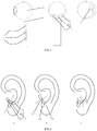
FIG. 2 is a schematic diagram of capacitive sensing units of a wearingsensor 2 of the earbud at three wearing positions according to an embodiment of the present application; -
FIG. 3 is a second structural diagram of an earbud according to an embodiment of the present application; -
FIG. 4 is a schematic diagram of capacitive sensing units of a touch sensor according to an embodiment of the present application; and -
FIG. 5 is a flowchart of a method for implementing a wearing detection and a touch operation according to an embodiment of the present application. - To make the objectives, technical solutions, and advantages of the present application clearer, the following elaborates part of embodiments of the present application by example with reference to the accompanying drawings. However, it should be understood by persons of ordinary skill in the art that, in the examples, numerous technical details are set forth in order to provide a reader with a better understanding of the present application. However, the technical solutions of the present application may also be implemented without these technical details and various variations and modifications based on the following embodiments.
- Refer to
FIG. 1 , which is a first structural diagram of an earbud according to an embodiment of the present application. This embodiment is described based on the earbud model inFIG. 1 , but a person skilled in the art should understand that the earbud model is only exemplary, and in actual use, the person skilled in the art may select other models to implement this solution by referring to the solution of the embodiment of the present application. InFIG. 1 , the earbud includes ahead 3 and astem 6, but it should be apparent to persons skilled in the art that in actual use, they may also select an earbud without a stem to implement this solution. In addition, this embodiment is exemplified by one earbud, but it should be understood by a person skilled in the art that one earbud is only an exemplary description, and in actual use, the person skilled in the art may select a pair of earbuds to implement this solution with reference to the solution of the embodiment of the present application. It should be noted that the wearing detections or touch operations of multiple earbuds may be or may not be independent of each other, which is not limited in this embodiment. In addition, this embodiment is exemplified by a cable-free true wireless earbud, but it should be understood by a person skilled in the art that the cable-free true wireless earbud is only an exemplary description, and in actual use, the person skilled in the art may select other types of earbuds to implement this solution with reference to the solution of the embodiment of the present application, including, but not limited to, wired earbuds and wireless earbuds having a cable between two earbuds. - The earbud includes at least two wearing sensors. As shown in
FIG. 1 , in this embodiment, the earbud is exemplified by an earbud including two wearing sensors, but it should be understood by a person skilled in the art that the earbud including two wearing sensors is only an exemplary description, and in actual use, the person skilled in the art may select an earbud including more than two wearing sensors to implement this solution with reference to the solution of the embodiment of the present application. Each wearing sensor includes at least one capacitive sensing unit. InFIG. 1 , the wearing sensor 1 includes a capacitive sensing unit, and the wearingsensor 2 includes three capacitive sensing units, respectively acapacitive sensing unit 21, acapacitive sensing unit 22, and acapacitive sensing unit 23. The wearing sensors in this embodiment respectively include one and three capacitive sensing units. It should be understood by a person skilled in the art that the wearing sensors respectively including one and three capacitive sensing units is only an exemplary description, and in actual use, the person skilled in the art may select the wearing sensors including any number of capacitive sensing units to implement this solution with reference to the solution of the embodiment of the present application. Thecapacitive sensing unit 21, thecapacitive sensing unit 22, and thecapacitive sensing unit 23 of the wearingsensor 2 in the embodiment of the present application are adjacent. This embodiment is exemplified by the wearing sensor including three adjacent capacitive sensing units, but it should be understood by a person skilled in the art that the situation of adjacent capacitive sensing units of the wearing sensor is only an exemplary description, and in actual use, the person skilled in the art may select the wearing sensor including capacitive sensing units that are not adjacent to implement this solution with reference to the solution of the embodiment of the present application. - In the embodiment of the present application, as shown in
FIG. 1 , thecapacitive sensing unit 21, thecapacitive sensing unit 22, and thecapacitive sensing unit 23 of the wearing sensor 1 are all quadrangular, but it should be understood by a person skilled in the art that the capacitive sensing units may be in various shapes. In actual use, the person skilled in the art may select the capacitive sensing units of different shapes and sizes to implement this solution, e.g., regular shapes such as triangles and pentagons and other irregular shapes, with reference to the solution of the embodiment of the present application. - In the embodiment of the present application, the two wearing sensors are arranged at different positions where the head of the earbud is in direct contact with skin tissues in the ear. As shown in
FIG. 1 , the wearing sensor 1 is arranged near a bell mouth, and the wearingsensor 2 is arranged at the bottom of the head of the earbud. The wearing sensors in this embodiment are respectively arranged near the bell mouth and at the bottom of the head of the earbud. It should be understood by a person skilled in the art that the wearing sensors arranged near the bell mouth and at the bottom of the head of the earbud is only an exemplary description, and in actual use, the person skilled in the art may set the wearing sensors at other different positions to implement this solution by referring to the solution of the embodiment of the present application. When the user wears the earbud, if the skin tissues of the ear are in contact with the wearing sensors, the capacitance values on the capacitive sensing units of the wearing sensors change, so that the function of wearing detection can be realized based on the capacitance values on the wearing sensors. On the one hand, when the earbud is held by hand, if the hand is in contact with the wearing sensors, the capacitance values change. On the other hand, when the table is in contact with the wearing sensors, the capacitance values on the capacitive sensing units also change. Accordingly, if the capacitance value detected on only one wearing sensor is used as the basis of wearing detection, the earbud is easily misjudged to be in a worn state due to false touch. In the embodiment of the present application, the capacitance values detected from all the wearing sensors are used as the basis for detecting that the earbud is in the worn state, and because the wearing sensor 1 and the wearingsensor 2 are at different positions, the wearing sensor 1 and the wearingsensor 2 are generally not touched at the same time, and therefore misjudgment caused by false touch on the earbud can be greatly reduced, and the accuracy of wearing detection is significantly improved. - In the embodiment of the present application, a maximum capacitance value or a sum of capacitance values detected on the capacitive sensing units of any wearing sensor is used as the maximum detection value of each wearing sensor, and when the maximum detection values of all the wearing sensors are not smaller than wearing thresholds, the earbud is determined to be worn. It should be noted that the wearing thresholds may be the same or different for different wearing sensors. In addition, it should be noted that the sum of capacitance values detected on the capacitive sensing units of any wearing sensor may be the sum of capacitance values detected on part of or all of the capacitive sensing units of any wearing sensor, which is not limited herein.
- Optionally, in an embodiment, as shown in
FIG. 1 , the capacitance value detected on the capacitive sensing unit of the wearing sensor 1 is used as the maximum detection value of the wearing sensor 1, and the sum of the detected capacitance values or the maximum capacitance value of the three capacitive sensing units of the wearingsensor 2 may be used as the maximum detection value of the wearingsensor 2. When the maximum detection values of the wearingsensors 1 and 2 are respectively not smaller than the wearing thresholds of the wearingsensors 1 and 2, the earbud is determined to be worn. It should be noted that the same wearing threshold or different wearing thresholds may be set for the wearingsensors 1 and 2, which is not limited in the embodiment of the present application. - The wearing position of the earbud directly affects the user experience, and the incorrectly-wearing position not only causes the problem of easy falling off, but also affects the audio experience more easily. In order to guide the user to wear correctly, whether the user's wearing position is correct needs to be detected. The wearing sensors include at least one first wearing sensor, the first wearing sensor including at least two capacitive sensing units; and when the capacitance value detected on any capacitive sensing unit of any first wearing sensor is smaller than a correctly-wearing threshold, the earbud is determined to be not correctly worn. It should be noted that whether the earbud is correctly worn is detected only in the worn state. In the embodiment of the present application, the wearing sensor including three capacitive sensing units is selected as the first wearing sensor for detecting whether the earbud is correctly worn. Specifically, when the capacitance values detected on all the capacitive sensing units of all the first wearing sensors are greater than or equal to the correctly-wearing thresholds, the earbud is determined to be correctly worn. As shown in
FIG. 1 , the wearingsensor 2 includes three capacitive sensing units, respectively acapacitive sensing unit 21, acapacitive sensing unit 22, and acapacitive sensing unit 23, so the wearingsensor 2 may be used as the first wearing sensor. The first wearing sensor in this embodiment includes three capacitive sensing units. It should be understood by a person skilled in the art that the first wearing sensor including three capacitive sensing units is only an exemplary description, and the first wearing sensor may include two or more capacitive sensing units. In the embodiment of the present application, when the earbud is worn, if any capacitance value detected on thecapacitive sensing unit 21, thecapacitive sensing unit 22, and thecapacitive sensing unit 23 is smaller than the correctly-wearing thresholds corresponding to thecapacitive sensing unit 21, thecapacitive sensing unit 22, and thecapacitive sensing unit 23, the earbud is determined to be not correctly worn. It should be noted that, when the earbud is in the worn state, the capacitive sensing units at different positions contact differently, and therefore the capacitance values of the capacitive sensing units are also different, so the correctly-wearing thresholds corresponding to thecapacitive sensing unit 21, thecapacitive sensing unit 22 and thecapacitive sensing units 23 may be the same or different, which is not limited in this embodiment. There is only one first wearing sensor in this embodiment, but it should be understood by a person skilled in the art that the earbud including a first wearing sensor is only an exemplary description, and the earbud may further include a plurality of first wearing sensors. In this embodiment, in the presence of only one first wearing sensor, it only needs to determine whether the first wearing sensor satisfies the condition of correctly-wearing in the worn state. In the presence of multiple first wearing sensors, it needs to determine whether each first wearing sensor satisfies the condition of correctly wearing, and if all satisfy, the earbud is correctly worn. - In this embodiment, three wearing cases of the earbud are represented by three different positions of the wearing
sensor 2. As shown inFIG. 2 , the wearingsensor 2 includes threecapacitive sensing units FIG. 2(a) describes the position of the wearingsensor 2 when the earbud is correctly worn, and at this wearing position, the earbud is unlikely to fall off and the user's tone experience is good. According toFIG. 2(a) , thecapacitive sensing unit 21 is in contact with anantitragus 52, and thecapacitive sensing unit 23 is in contact with atragus 53, and thecapacitive sensing unit 22 is above aninter-tragus incisura 51 and is substantially not in contact with the ear. Because the capacitance values become large when the capacitive sensing units are in contact with the ear, the capacitance values of thecapacitive sensing units capacitive sensing unit 22 is smaller. As shown inFIG. 2(b) , thecapacitive sensing units tragus 53, and thecapacitive sensing unit 21 is above theinter-tragus incisura 51 and is substantially not in contact with the ear, and under the present circumstances, the capacitance values of thecapacitive sensing units capacitive sensing unit 21 is smaller. As shown inFIG. 2(c) , thecapacitive sensing units antitragus 52, and thecapacitive sensing unit 23 is above theinter-tragus incisura 51 and is substantially not in contact with the ear, and under the present circumstances, the capacitance values of thecapacitive sensing units capacitive sensing unit 23 is smaller. Corresponding correctly-wearing thresholds may be set for the three capacitive sensing units of the wearingsensor 2 to determine whether the earbud is at the correctly-wearing position. In this embodiment, large correctly-wearing thresholds may be set for thecapacitive sensing units capacitive sensing unit 22. It should be noted that the solution of setting the correctly-wearing thresholds in this embodiment is only an exemplary description, and persons skilled in the art may set the correctly-wearing thresholds for the capacitive sensing units of the wearing sensor by using different solutions based on different usage requirements. - Preferably, when the earbud is not correctly worn, the user may also be prompted to adjust the wearing position. For example, in the case of
FIG. 2(a) , the capacitance values of thecapacitive sensing units capacitive sensing unit 22 is smaller, which belongs to a correctly-wearing state, so prompt may not be set; in the case ofFIG. 2(b) , the capacitance values of thecapacitive sensing units capacitive sensing unit 21 is smaller, and then the user may be prompted to rotate the earbud counterclockwise, so as to increase the capacitance value of thecapacitive sensing unit 21 and reduce the capacitance value of thecapacitive sensing unit 22 to the correctly-wearing state; in the case ofFIG. 2(c) , the capacitance values of thecapacitive sensing units capacitive sensing unit 23 is smaller, and the user may be prompted to rotate the earbud clockwise, so as to increase the capacitance value of thecapacitive sensing unit 23 and reduce the capacitance value of thecapacitive sensing unit 22 to the correctly-wearing state. In addition, the user may also be prompted to adjust the angle of clockwise or counterclockwise rotation when the wearing position is adjusted based on differences between the detected capacitance values and the correctly-wearing thresholds. - Optionally, the capacitive sensing units of the wearing sensors may be directly arranged on the inner surface of an earbud housing, or arranged inside the earbud housing by an injection molding process or other process.
-
FIG. 3 is a second structural diagram of the earbud according to an embodiment of the present application. Optionally, the earbud further includes a touch sensor and a detection processing circuit, where the detection processing circuit of the earbud is configured to detect and process the capacitance values of the wearing sensor and the touch sensor, the wearing sensor and the touch sensor is connected with the detection processing circuit, and the wearing sensor and the touch sensor share the detection processing circuit, so that touch and wearing detections may be simultaneously implemented without an additional hardware circuit, and the cost can be greatly reduced, and the difficulty in integration is reduced. The touch sensor is arranged at on the head or stem of the earbud away from the ear, and is configured to detect a touch operation when the earbud is worn. The triggering method for the touch sensor includes, but is not limited to, touch or slide during touch. - Optionally, the detection processing circuit includes a driver; as shown in
FIG. 3 , the touch sensor includes capacitive sensing units; the touch sensor and the wearing sensors, which both include capacitive sensing units, may share a driving circuit; and the driver is connected with all the capacitive sensing units of the wearing sensors and the touch sensor, and is configured to drive all the capacitive sensing units of the wearing sensors and the touch sensor. - Optionally, the detection processing circuit includes a multiplexer; and the multiplexer is connected with the wearing sensors and the touch sensor, and is configured to select capacitance signals acquired by all the capacitive sensing units of the wearing sensors and the touch sensor. As shown in
FIG. 3 , the detection processing circuit further includes a capacitance detection circuit, an analog-to-digital converter, and a processor. In the absence of the multiplexer, each capacitive sensing unit may also correspond to a set of capacitance detection circuit and analog-to-digital converter, but this increases the cost and is unfavorable for integration. - Optionally, all the capacitive sensing units of the touch sensor are arranged on the inner surface of the earbud housing or inside the housing. Like the wearing sensor, the capacitive sensing units of the touch sensor may be directly arranged on the inner surface of the earbud housing, or arranged inside the earbud housing by an injection molding process or other process, as shown in
FIG. 4 . InFIG. 4(a) , thecapacitive sensing units touch sensor 4 may be directly arranged on theinner surface 62 of the housing of the earbud stem. InFIG. 4(b) , the capacitive sensing units of the touch sensor are arranged inside the housing of the earbud stem, that is, between theinner surface 62 andouter surface 61 of the housing of the earbud stem. In addition, this embodiment is exemplified by quadrangular capacitive sensing units, but the shape and size of the capacitive sensing units of the touch sensor are not limited. Moreover, this embodiment is exemplified by the capacitive sensing units at the earbud stem, but the positions of the capacitive sensing units are not limited, and the capacitive sensing units of the touch sensor may also be arranged at the head of the earbud. - Optionally, the detection processing circuit includes a main control chip. When the state is worn and unworn, the main control chip may update the current wearing state with preset frequencies, so that wearing action of the user may be monitored at any time. The preset frequencies for updating the current wearing state in the worn and unworn states may be different.
- The embodiment of the present disclosure provides an earbud, which solves the problem of misjudgment on wearing detection due to false touch, can prevent the earbud placed on a table or held by hand from being misjudged to be worn, and remarkably improves the accuracy of wearing detection.
- This embodiment further provides a method for implementing a wearing detection and a touch operation. The method is applied to the earbud. As shown in
FIG. 5 , the method includes: - Step 51: capacitance values of all wearing sensors are acquired;
- Step 52: whether the maximum detection value of each wearing sensor is not smaller than a wearing threshold is determined;
- Step 53: if yes, the earbud is determined to be in a worn state, and the touch sensor is set to be in a working state.
- Whether the earbud is worn is determined based on the values of capacitive sensing units of a plurality of wearing sensors at different positions, which can greatly reduce misjudgment problems caused by false touch and improve the accuracy of wearing detection. When the wearing state is the worn state, the touch sensor is set to be in a working state. Only when the earbud is in the worn state, the earbud responds to user's touch operation. When the earbud is taken off, it can automatically enter a low power mode, without responding to user's touch operation. When the earbud is worn, it can quickly wake up from "sleep" and quickly respond to a user operation, which can achieve the purpose of saving energy, and especially can significantly improve the endurance for a battery-powered wireless earbud.
- Optionally, if the earbud is worn, the following steps may be executed:
- Step 54: whether any capacitance value detected on all capacitive sensing units of any first wearing sensor is smaller than a correctly-wearing threshold is determined;
- Step 55: if yes, the earbud is determined to be not correctly worn, and a prompt for adjusting the wearing position is set.
- In order to guide the user to wear correctly, whether the user's wearing position is correct needs to be detected. It should be noted that whether the earbud is correctly worn is detected only in the worn state. When the earbud is in the worn state, the capacitive sensing units at different positions contact with the skin differently, and therefore the capacitance values of the capacitive sensing units are also different, so whether the earbud is correctly worn may be determined based on the capacitance values of the capacitive sensing units, where when the capacitance value on each capacitive sensing unit of the first wearing sensor is not smaller than the correctly-wearing threshold corresponding to the capacitive sensing unit, the first wearing sensor is at the corresponding position when the earbud is correctly worn, and the earbud can be determined to be correctly worn when all the first wearing sensors satisfy the condition; and when the earbud is not correctly worn, a prompt for adjusting the wearing position of the earbud may be set based on the capacitance values of the capacitive sensing units of the first wearing sensor, and the user may adjust the wearing position of the earbud based on the prompt. How to set the prompt for adjusting the wearing position of the earbud based on the capacitance values of the capacitive sensing units has been exemplified in the foregoing, and details are not described herein again.
- In addition, the current wearing state of the earbud also needs to be updated with a preset frequency, so that the user's operation of taking off or wearing the earbud can be detected and responded in time. It should be noted that, in the worn state, the current wearing state of the earbud needs to be updated with a preset frequency, and in the unworn state, the current wearing state of the earbud may also be updated with a preset frequency, where the preset frequencies in the two cases may be different or the same, which is not limited in this embodiment.
- Optionally, the function of step counting detection may be realized by using the wearing sensor. During movement, the contact between the capacitive sensing units of the wearing sensor and the skin may change, so the maximum detection value of the wearing sensor may jitter. When the amount of jitter is not smaller than a step jitter threshold, an operation of step increase is performed to update the current step data. It should be noted that, when the amount of jitter is not smaller than the step jitter threshold, the number of steps may be increased by 1 or 2. How many steps are increased may be determined based on the magnitude of jitter, which is not limited in this embodiment.
- The embodiment of the present application provides a method for implementing a wearing detection and a touch operation. The method is applied to the earbud, solves the problem of misjudgment on wearing detection due to false touch, can prevent the earbud placed on a table or held by hand from being misjudged to be worn, and remarkably improves the accuracy of wearing detection.
- It should be noted that the above method embodiment of the present application may be applied to a processor or implemented by a processor. The processor may be an integrated circuit chip with signal processing capability. In the implementation process, each step of the method embodiment may be completed by an integrated logic circuit of hardware in the processor or by an instruction in the form of software. The processor may be a general-purpose processor, a digital signal processor (DSP), an application specific integrated circuit (ASIC), a field programmable gate array (FPGA) or other programmable logic device, discrete gate or transistor logic device, or discrete hardware component. The processor may implement or execute the methods, steps, and logical block diagrams disclosed in the embodiments of the present application. The general-purpose processor may be a microprocessor or any conventional processor, etc. The steps of the methods disclosed in the embodiments of the present application may be directly implemented by a hardware decoding processor, or by a combination of hardware and software modules in the decoding processor. The software modules may be located in a storage medium mature in the art, such as a random access memory, a flash memory, a read-only memory, a programmable read-only memory, an electrically erasable programmable memory, or a register. The storage medium is located in a memory, and the processor reads the information in the memory and combines the hardware to complete the steps of the above method.
- It should be understood that the memory in the embodiments of the present application may be a volatile memory or a non-volatile memory, or include both volatile and non-volatile memories. The non-volatile memory may be a read-only memory (ROM), a programmable ROM (PROM), an erasable PROM (EPROM), an electrically EPROM (EEPROM) or a flash memory. The volatile memory may be a random access memory (RAM) serving as an external cache. By exemplary but not restrictive description, many forms of RAM are available, such as a static RAM (SRAM), a dynamic RAM (DRAM), a synchronous DRAM (SDRAM), a double data rate SDRAM (DDR SDRAM), an enhanced SDRAM (ESDRAM), a synchlink DRAM (SLDRAM), and a direct rambus RAM (DR RAM). It should be noted that the memories of the systems and methods described herein are intended to include, but not limited to, these and any other suitable types of memories.
- It should be understood that, in the embodiments of the present application, "B corresponding to A" indicates that B is associated with A, and B may be determined from A. However, it should also be understood that, the determination of B from A does not indicate that B is only determined from A, but may also be determined from A and/or other information.
- In addition, the term "and/or" is merely an association relationship describing associated objects, indicating three relationships, for example, A and/or B may indicate that A exists alone, A and B exist at the same time, and B exists alone. In addition, the character "/" generally indicates that the associated objects are in an "or" relationship.
- Persons of ordinary skill in the art may realize that the units and algorithmic steps of each example described in combination with the embodiments disclosed herein may be implemented by electronic hardware, or a combination of computer software and electronic hardware. Whether these functions are executed by hardware or software depends on a specific application and design constraint conditions of the technical solution. Professionals may implement the described functions for each specific application by using different methods, but such implementation should not be considered beyond the scope of the present application.
- Persons skilled in the art may clearly understand that, for the sake of convenience and briefness in description, for the specific working processes of the above-described systems, apparatuses and units, reference may be made to the corresponding processes in the embodiments of the aforementioned methods, and details are not described herein again.
- In the several embodiments provided in the application, it shall be understood that the disclosed systems, devices and methods may be realized in other modes. For example, the above-described device embodiment is only exemplary, for example, the division of the units is only a logic function division, other division modes may be adopted in practice, e.g., a plurality of units or components may be combined or integrated in another system, or some characteristics may be omitted or are not executed. In addition, the displayed or discussed mutual couplings or direct couplings or communication connections may be implemented by some interfaces. The indirect couplings or communication connections between devices or units may be implemented in electronic, mechanical, or other forms.
- The units illustrated as separate components may be or may not be physically separated, and the components displayed as units may be or may not be physical units, that is to say, the components may be positioned at one place or may also be distributed on a plurality of network units. The objectives of the solutions of the embodiments may be fulfilled by selecting part of or all of the units according to actual needs.
- In addition, the functional units in the embodiments of the present application may be integrated into one processing unit, or each of the units may exist alone physically, or two or more units may be integrated into one unit.
- When the functions are realized in the form of software functional units and sold or used as independent products, the functions may be stored in computer readable storage mediums. Based on such an understanding, the technical solution of the present application substantially, or the part of the present disclosure making contribution to the prior art, or a part of the technical solution may be embodied in the form of a software product, and the computer software product is stored in a storage medium, which includes a plurality of instructions enabling a computer device (which may be a personal computer, a server, or a network device, etc.) to execute all of or part of the steps in the methods of the embodiments of the present application. The aforementioned storage medium includes: various media capable of storing program codes, such as a U disk, a mobile hard disk, a read-only memory (ROM), a random access memory (RAM), a magnetic disk or an optical disk.
- Described above are merely specific embodiments of the present application, but the scope of the present application is not limited to this, any skilled who is familiar with this art could readily think of variations or substitutions within the disclosed technical scope of the present application, and these variations or substitutions shall fall within the scope of the present application. Thus, the scope of the present application shall be subjected to the scope of the claims.
Claims (13)
the touch sensor is arranged on the head or a stem of the earbud away from the ear, and is configured to detect a touch operation when the earbud is in the worn state; and
the at least two wearing sensors and the touch sensor are connected with the detection processing circuit, and share the detection processing circuit.
the driver is connected with all the capacitive sensing units of the at least two wearing sensors and the touch sensor, and is configured to drive all the capacitive sensing units of the at least two wearing sensors and the touch sensor.
the multiplexer is connected with the at least two wearing sensors and the touch sensor, and is configured to select capacitance signals acquired by all the capacitive sensing units of the at least two wearing sensors and the touch sensor.
the main control chip is configured to update a current wearing state with a preset frequency.
Applications Claiming Priority (1)
| Application Number | Priority Date | Filing Date | Title |
|---|---|---|---|
| PCT/CN2018/107390 WO2020061761A1 (en) | 2018-09-25 | 2018-09-25 | Earphone and method for implementing wearing detection and touch operation |
Publications (3)
| Publication Number | Publication Date |
|---|---|
| EP3855757A1 true EP3855757A1 (en) | 2021-07-28 |
| EP3855757A4 EP3855757A4 (en) | 2022-01-26 |
| EP3855757B1 EP3855757B1 (en) | 2023-03-22 |
Family
ID=68849318
Family Applications (1)
| Application Number | Title | Priority Date | Filing Date |
|---|---|---|---|
| EP18935553.0A Active EP3855757B1 (en) | 2018-09-25 | 2018-09-25 | Earphone and method for implementing wearing detection and touch operation |
Country Status (5)
| Country | Link |
|---|---|
| US (2) | US10999667B2 (en) |
| EP (1) | EP3855757B1 (en) |
| KR (1) | KR102434142B1 (en) |
| CN (2) | CN110603815B (en) |
| WO (1) | WO2020061761A1 (en) |
Cited By (1)
| Publication number | Priority date | Publication date | Assignee | Title |
|---|---|---|---|---|
| WO2025023969A1 (en) * | 2023-07-25 | 2025-01-30 | Google Llc | Capacitive on-head detection using a magnetically-sensitive section |
Families Citing this family (61)
| Publication number | Priority date | Publication date | Assignee | Title |
|---|---|---|---|---|
| USD681015S1 (en) * | 2012-09-08 | 2013-04-30 | Apple Inc. | Earphone |
| US11070904B2 (en) | 2018-09-21 | 2021-07-20 | Apple Inc. | Force-activated earphone |
| US11463797B2 (en) | 2018-09-21 | 2022-10-04 | Apple Inc. | Force-activated earphone |
| CN110114738B (en) * | 2019-03-25 | 2020-12-01 | 深圳市汇顶科技股份有限公司 | Wearable device, wear detection method and storage medium |
| CN112188338B (en) * | 2019-07-04 | 2024-12-24 | 缤特力股份有限公司 | Earphone and method for activating earphone |
| CN114208206A (en) * | 2019-08-04 | 2022-03-18 | 卫保数码有限公司 | Earpiece capable of interacting with the tragus and method of providing continuous physiological detection |
| WO2021087121A1 (en) * | 2019-11-01 | 2021-05-06 | Starkey Laboratories, Inc. | Ear-based biometric identification |
| KR102227134B1 (en) * | 2019-11-13 | 2021-03-15 | 주식회사 이엠텍 | Wireless ear bud having contact point outside of ear |
| US11863927B2 (en) * | 2019-11-20 | 2024-01-02 | Bose Corporation | Audio device proximity detection |
| USD941276S1 (en) * | 2020-05-08 | 2022-01-18 | Navajo Manufacturing Company, Inc. | Earbud |
| CN211180797U (en) | 2020-06-23 | 2020-08-04 | 深圳市汇顶科技股份有限公司 | Capacitance detection devices and electronic equipment |
| KR102800763B1 (en) * | 2020-07-24 | 2025-04-28 | 삼성전자주식회사 | Electronic device sensing touch input and method thereof |
| CN112055296B (en) * | 2020-08-03 | 2022-11-18 | 歌尔科技有限公司 | Earphone wearing state detection method and device and earphone |
| CN111988692B (en) * | 2020-08-07 | 2022-11-15 | 歌尔科技有限公司 | Earphone wearing state detection method and device, earphone and storage medium |
| CN115052221A (en) * | 2020-08-19 | 2022-09-13 | 芯海科技(深圳)股份有限公司 | Earphone control method and earphone |
| USD930623S1 (en) * | 2020-08-20 | 2021-09-14 | Shenzhen Nearbyexpress Technology Development Company Limited | Earphone and earphone box |
| CN112104938B (en) * | 2020-09-01 | 2023-05-12 | 深圳市卓翼科技股份有限公司 | Anti-falling method and device for true wireless Bluetooth headset and true wireless Bluetooth headset |
| KR102870564B1 (en) | 2020-09-23 | 2025-10-15 | 삼성전자주식회사 | Wearable device and method for controlling thereof |
| USD963613S1 (en) * | 2020-09-30 | 2022-09-13 | Shenzhen Zio Communication Technology Co., Ltd. | Earphone |
| CN112449297B (en) * | 2020-10-19 | 2022-04-29 | 安克创新科技股份有限公司 | A kind of detection method of earphone wearing state |
| CN112333592B (en) * | 2020-10-29 | 2022-10-18 | 歌尔科技有限公司 | Earphone for detecting material of earmuffs |
| CN112546439B (en) * | 2020-11-19 | 2025-09-16 | 未来穿戴技术有限公司 | Wearing detection method of massage instrument, massage instrument and readable storage medium |
| CN112468922A (en) * | 2020-11-26 | 2021-03-09 | 芯海科技(深圳)股份有限公司 | Earphone interaction method and earphone |
| CN114557686A (en) * | 2020-11-27 | 2022-05-31 | 阿里巴巴集团控股有限公司 | Skin moisture detection method, device and equipment and computer readable storage medium |
| CN112738679A (en) * | 2020-12-24 | 2021-04-30 | Oppo广东移动通信有限公司 | Signal transceivers, electronic devices, wearable devices and wireless earphones |
| US11818525B2 (en) * | 2020-12-30 | 2023-11-14 | Techonu, Limited | Wearable HCI device |
| US11589150B2 (en) * | 2021-01-07 | 2023-02-21 | Apple Inc. | Wireless listening device |
| US11785372B2 (en) | 2021-01-07 | 2023-10-10 | Apple Inc. | Wireless listening device |
| USD925500S1 (en) * | 2021-01-13 | 2021-07-20 | Shenzhen Sixpipes Technology Co., Ltd | Wireless earphone |
| CN112911484A (en) * | 2021-01-27 | 2021-06-04 | 维沃移动通信有限公司 | Earphone state detection method and device |
| EP4067850A4 (en) * | 2021-02-09 | 2022-10-05 | Shenzhen Goodix Technology Co., Ltd. | Pressure detection module and electronic device |
| EP4068800A4 (en) | 2021-02-09 | 2022-10-05 | Shenzhen Goodix Technology Co., Ltd. | Pressure detection module and electronic device |
| KR102628612B1 (en) | 2021-02-10 | 2024-01-23 | 선전 구딕스 테크놀로지 컴퍼니, 리미티드 | Method for determining capacitance standard value, devices and equipment for determining capacitance standard value |
| CN115250400A (en) * | 2021-04-28 | 2022-10-28 | 深圳市韶音科技有限公司 | A kind of wireless earphone and connection method of wireless earphone |
| CN115334390B (en) * | 2021-05-10 | 2025-01-28 | Oppo广东移动通信有限公司 | State detection calibration method, device, wireless headset and storage medium |
| CN113794971A (en) * | 2021-07-29 | 2021-12-14 | RealMe重庆移动通信有限公司 | Earphone, earphone control method, earphone control device and storage medium |
| JP1713162S (en) * | 2021-08-06 | 2022-04-21 | earphone | |
| CN113703659B (en) * | 2021-09-01 | 2024-06-11 | 恒玄科技(上海)股份有限公司 | State detection method and device, wearable device, and readable storage medium |
| CN113613138A (en) * | 2021-09-06 | 2021-11-05 | 合肥松豪电子科技有限公司 | A method for realizing wearing feedback, touch detection and hand-held recognition of earphones |
| CN114003149A (en) * | 2021-09-30 | 2022-02-01 | 深圳曦华科技有限公司 | Electronic equipment control method and device, electronic equipment and storage medium |
| CN113709623B (en) * | 2021-10-28 | 2022-03-25 | 易兆微电子(杭州)股份有限公司 | A headset control method, device, headset and storage medium |
| CN114079840B (en) * | 2021-11-02 | 2025-08-15 | 深圳市飞科笛系统开发有限公司 | Earphone wearing sensing circuit, headset and electronic equipment |
| WO2023095975A1 (en) * | 2021-11-29 | 2023-06-01 | 엘지전자 주식회사 | Portable electronic device |
| JP2023102075A (en) * | 2022-01-11 | 2023-07-24 | パナソニックIpマネジメント株式会社 | Headphones and how to control them |
| CN114459510B (en) * | 2022-01-30 | 2023-12-26 | 深圳市汇顶科技股份有限公司 | Capacitive sensor, wear detection device and wearing equipment |
| CN114501292B (en) * | 2022-02-28 | 2025-01-21 | 潍坊歌尔电子有限公司 | Headphone wearing detection method, device, headphone equipment and storage medium |
| CN114745651B (en) * | 2022-02-28 | 2023-04-25 | 潍坊歌尔电子有限公司 | Headset state detection method, headset and computer readable storage medium |
| CN114630242B (en) * | 2022-03-23 | 2024-04-09 | 歌尔股份有限公司 | Headphone wearing detection method, headphone and storage medium |
| CN114827805B (en) * | 2022-03-29 | 2025-06-24 | 歌尔股份有限公司 | Method and device for detecting earphone wearing status, earphone and readable storage medium |
| CN114745627B (en) * | 2022-03-31 | 2025-12-05 | 恒玄科技(上海)股份有限公司 | A wireless earphone and a method for detecting in-ear and out-of-ear sounds. |
| CN114827808B (en) * | 2022-04-11 | 2024-12-17 | Oppo广东移动通信有限公司 | Earphone control method, earphone control device and earphone |
| CN115278431B (en) * | 2022-06-24 | 2024-10-22 | 维沃移动通信有限公司 | State determination method and device, electronic device and readable storage medium |
| USD985542S1 (en) * | 2022-11-04 | 2023-05-09 | Shen Zhen Ocen Technology Co. Ltd | Earphone |
| USD986860S1 (en) * | 2022-11-04 | 2023-05-23 | Shen Zhen Ocen Technology Co. Ltd | Earphone |
| USD989748S1 (en) * | 2022-11-25 | 2023-06-20 | Zhijun Wu | Earphone |
| USD993941S1 (en) * | 2022-11-25 | 2023-08-01 | Zhijun Wu | Earphone |
| US20250106546A1 (en) * | 2023-09-22 | 2025-03-27 | Apple Inc. | Capacitive in ear detect on earphones |
| US20250274693A1 (en) * | 2024-02-27 | 2025-08-28 | Bose Corporation | Earpieces with capacitive touch interfaces |
| US20240319829A1 (en) * | 2024-05-29 | 2024-09-26 | Google Llc | Touch-Sensing Pattern for Multi-Angular Orientations |
| WO2025258809A1 (en) * | 2024-06-12 | 2025-12-18 | 삼성전자주식회사 | Wearable device and method for identifying touch input and pressure input |
| CN121940680A (en) * | 2024-10-28 | 2026-04-28 | 深圳市韶音科技有限公司 | A wearable device capable of detecting wear |
Family Cites Families (30)
| Publication number | Priority date | Publication date | Assignee | Title |
|---|---|---|---|---|
| US8428289B2 (en) * | 2007-06-13 | 2013-04-23 | Innovelis, Inc. | Headphone adaptation and positioning device |
| US8259984B2 (en) * | 2007-06-29 | 2012-09-04 | Sony Ericsson Mobile Communications Ab | Headset with on-ear detection |
| US9094764B2 (en) * | 2008-04-02 | 2015-07-28 | Plantronics, Inc. | Voice activity detection with capacitive touch sense |
| CN201226587Y (en) * | 2008-06-26 | 2009-04-22 | 昆盈企业股份有限公司 | Touch Bluetooth earphone |
| US8401218B2 (en) * | 2010-07-29 | 2013-03-19 | Microsoft Corporation | Adjustable earphone and earphone set |
| JP3192221U (en) * | 2011-04-05 | 2014-08-07 | ブルー−ギア, エルエルシーBlue−Gear, Llc | Universal earpiece |
| CN103002373B (en) * | 2012-11-19 | 2015-05-27 | 青岛歌尔声学科技有限公司 | Earphone and method for detecting earphone wearing state |
| US9398365B2 (en) * | 2013-03-22 | 2016-07-19 | Otter Products, Llc | Earphone assembly |
| CN106464996A (en) * | 2014-01-24 | 2017-02-22 | 布拉吉有限公司 | Versatile headphone system for sports activities |
| US10698996B2 (en) * | 2014-07-08 | 2020-06-30 | Pixart Imaging Inc. | Wearable device having higher security and skin sensor equipped thereon |
| CN104506987B (en) * | 2014-11-27 | 2018-02-27 | 青岛歌尔声学科技有限公司 | A kind of intelligent earphone control method and a kind of intelligent earphone |
| US9924270B2 (en) * | 2015-01-09 | 2018-03-20 | Intel Corporation | Techniques for channelization of stereo audio in headphones |
| US9838775B2 (en) * | 2015-09-16 | 2017-12-05 | Apple Inc. | Earbuds with biometric sensing |
| US10856068B2 (en) * | 2015-09-16 | 2020-12-01 | Apple Inc. | Earbuds |
| US10117012B2 (en) * | 2015-09-28 | 2018-10-30 | Apple Inc. | Wireless ear buds with proximity sensors |
| US20170155998A1 (en) * | 2015-11-27 | 2017-06-01 | Bragi GmbH | Vehicle with display system for interacting with wearable device |
| US9998817B1 (en) * | 2015-12-04 | 2018-06-12 | Google Llc | On head detection by capacitive sensing BCT |
| CN206920734U (en) * | 2016-01-22 | 2018-01-23 | 周常安 | Glasses type physiological sensing and wearing device and glasses structure |
| CN105554616B (en) * | 2016-02-29 | 2019-04-12 | 宇龙计算机通信科技(深圳)有限公司 | A kind of headset control method and earphone |
| CN109068994A (en) * | 2016-04-17 | 2018-12-21 | 莱夫毕恩技术有限公司 | Earphone with biosensor and stabilizing elements |
| CN106291121B (en) * | 2016-07-29 | 2023-10-13 | 歌尔股份有限公司 | Wearing state detection method of wearable device and wearable device |
| US10291975B2 (en) * | 2016-09-06 | 2019-05-14 | Apple Inc. | Wireless ear buds |
| CN107959903A (en) * | 2016-10-18 | 2018-04-24 | 中兴通讯股份有限公司 | Audio output switching method, feedback earphone wearing state method, apparatus and earphone |
| CN106792308A (en) * | 2016-12-06 | 2017-05-31 | 歌尔科技有限公司 | The control method and earphone of earphone |
| CN106792314B (en) * | 2016-12-29 | 2019-06-18 | 歌尔科技有限公司 | A kind of detection method of ear-sticking headphone and its wearing state |
| CN107065016B (en) * | 2017-03-01 | 2019-04-12 | 歌尔科技有限公司 | A kind of wearing detection method, device and headphone for headphone |
| US20190098390A1 (en) * | 2017-09-25 | 2019-03-28 | Apple Inc. | Earbuds With Capacitive Sensors |
| CN207560279U (en) * | 2017-11-27 | 2018-06-29 | 深圳市汇顶科技股份有限公司 | Earphone and electronic equipment |
| CN108151657A (en) | 2017-12-28 | 2018-06-12 | 上海传英信息技术有限公司 | A kind of dimension of object measuring method and measuring device based on intelligent terminal |
| US10728646B2 (en) * | 2018-03-22 | 2020-07-28 | Apple Inc. | Earbud devices with capacitive sensors |
-
2018
- 2018-09-25 WO PCT/CN2018/107390 patent/WO2020061761A1/en not_active Ceased
- 2018-09-25 CN CN201880027748.7A patent/CN110603815B/en active Active
- 2018-09-25 CN CN202110271832.7A patent/CN113038325B/en active Active
- 2018-09-25 KR KR1020217011667A patent/KR102434142B1/en active Active
- 2018-09-25 EP EP18935553.0A patent/EP3855757B1/en active Active
-
2019
- 2019-10-15 US US16/601,587 patent/US10999667B2/en active Active
-
2021
- 2021-04-06 US US17/223,405 patent/US11412319B2/en active Active
Cited By (1)
| Publication number | Priority date | Publication date | Assignee | Title |
|---|---|---|---|---|
| WO2025023969A1 (en) * | 2023-07-25 | 2025-01-30 | Google Llc | Capacitive on-head detection using a magnetically-sensitive section |
Also Published As
| Publication number | Publication date |
|---|---|
| US10999667B2 (en) | 2021-05-04 |
| EP3855757A4 (en) | 2022-01-26 |
| US20200100010A1 (en) | 2020-03-26 |
| CN110603815B (en) | 2021-03-26 |
| US20210227310A1 (en) | 2021-07-22 |
| CN110603815A (en) | 2019-12-20 |
| KR102434142B1 (en) | 2022-08-18 |
| CN113038325A (en) | 2021-06-25 |
| US11412319B2 (en) | 2022-08-09 |
| CN113038325B (en) | 2023-01-24 |
| EP3855757B1 (en) | 2023-03-22 |
| WO2020061761A1 (en) | 2020-04-02 |
| KR20210060591A (en) | 2021-05-26 |
Similar Documents
| Publication | Publication Date | Title |
|---|---|---|
| US11412319B2 (en) | Earbud and method for implementing wearing detection and touch operation | |
| CN110447242B (en) | Wear detection device, method and headset | |
| CN107534805B (en) | Sensor-based signal transmission method and device | |
| CN108712697B (en) | Wireless earphone and working mode determining method, device, equipment and storage medium thereof | |
| US11711644B2 (en) | Earphone and worn detection device thereof | |
| CN112055296B (en) | Earphone wearing state detection method and device and earphone | |
| EP3419258A1 (en) | Controlling power for a headset | |
| CN107291313B (en) | Fingerprint awakening control method and device, storage medium and mobile terminal | |
| CN103002373A (en) | Earphone and method for detecting earphone wearing state | |
| US10681451B1 (en) | On-body detection of wearable devices | |
| WO2021103266A1 (en) | Head-mounted device, wearing detection method and apparatus therefor, and medium | |
| CN111770409A (en) | Earphone loss prevention method, device, system and earphone | |
| US11979706B2 (en) | Neckband earphone and function switching method, system and device, and computer medium | |
| US20220174391A1 (en) | Knob-Like Input for a Hearable Device | |
| EP4422205A1 (en) | Earphone control method, related system and storage medium | |
| CN107544713A (en) | Capacitance plate control method, device and terminal device | |
| CN108387201B (en) | Opening and closing distance detection method, device and equipment | |
| CN114674069B (en) | Method and device for monitoring air conditioner, air conditioner and storage medium | |
| US11849272B2 (en) | Neckband headset, start up method, system, apparatus, and computer medium | |
| CN109302527A (en) | Terminal false-touch prevention method, terminal and computer readable storage medium | |
| CN114745627B (en) | A wireless earphone and a method for detecting in-ear and out-of-ear sounds. | |
| CN114745626B (en) | A method for detecting in-ear and out-of-ear sounds in wireless earphones, wireless earphones, and a storage medium. | |
| US20260129338A1 (en) | Wearable devices and tap detection methods thereof | |
| CN112162329B (en) | Proximity sensing detection method and device, storage medium and electronic equipment | |
| CN122069470A (en) | Earphone wearing detection method, earphone wearing detection device, terminal equipment and storage medium |
Legal Events
| Date | Code | Title | Description |
|---|---|---|---|
| STAA | Information on the status of an ep patent application or granted ep patent |
Free format text: STATUS: THE INTERNATIONAL PUBLICATION HAS BEEN MADE |
|
| PUAI | Public reference made under article 153(3) epc to a published international application that has entered the european phase |
Free format text: ORIGINAL CODE: 0009012 |
|
| STAA | Information on the status of an ep patent application or granted ep patent |
Free format text: STATUS: REQUEST FOR EXAMINATION WAS MADE |
|
| 17P | Request for examination filed |
Effective date: 20210423 |
|
| AK | Designated contracting states |
Kind code of ref document: A1 Designated state(s): AL AT BE BG CH CY CZ DE DK EE ES FI FR GB GR HR HU IE IS IT LI LT LU LV MC MK MT NL NO PL PT RO RS SE SI SK SM TR |
|
| RIC1 | Information provided on ipc code assigned before grant |
Ipc: H04R 1/10 20060101AFI20210917BHEP |
|
| DAV | Request for validation of the european patent (deleted) | ||
| DAX | Request for extension of the european patent (deleted) | ||
| A4 | Supplementary search report drawn up and despatched |
Effective date: 20220103 |
|
| RIC1 | Information provided on ipc code assigned before grant |
Ipc: H04R 1/10 20060101AFI20211220BHEP |
|
| GRAP | Despatch of communication of intention to grant a patent |
Free format text: ORIGINAL CODE: EPIDOSNIGR1 |
|
| STAA | Information on the status of an ep patent application or granted ep patent |
Free format text: STATUS: GRANT OF PATENT IS INTENDED |
|
| INTG | Intention to grant announced |
Effective date: 20221026 |
|
| RIN1 | Information on inventor provided before grant (corrected) |
Inventor name: CHENG, SHUQING Inventor name: YANG, MING |
|
| GRAS | Grant fee paid |
Free format text: ORIGINAL CODE: EPIDOSNIGR3 |
|
| GRAJ | Information related to disapproval of communication of intention to grant by the applicant or resumption of examination proceedings by the epo deleted |
Free format text: ORIGINAL CODE: EPIDOSDIGR1 |
|
| GRAL | Information related to payment of fee for publishing/printing deleted |
Free format text: ORIGINAL CODE: EPIDOSDIGR3 |
|
| STAA | Information on the status of an ep patent application or granted ep patent |
Free format text: STATUS: REQUEST FOR EXAMINATION WAS MADE |
|
| INTC | Intention to grant announced (deleted) | ||
| GRAP | Despatch of communication of intention to grant a patent |
Free format text: ORIGINAL CODE: EPIDOSNIGR1 |
|
| STAA | Information on the status of an ep patent application or granted ep patent |
Free format text: STATUS: GRANT OF PATENT IS INTENDED |
|
| GRAA | (expected) grant |
Free format text: ORIGINAL CODE: 0009210 |
|
| STAA | Information on the status of an ep patent application or granted ep patent |
Free format text: STATUS: THE PATENT HAS BEEN GRANTED |
|
| INTG | Intention to grant announced |
Effective date: 20230131 |
|
| AK | Designated contracting states |
Kind code of ref document: B1 Designated state(s): AL AT BE BG CH CY CZ DE DK EE ES FI FR GB GR HR HU IE IS IT LI LT LU LV MC MK MT NL NO PL PT RO RS SE SI SK SM TR |
|
| REG | Reference to a national code |
Ref country code: GB Ref legal event code: FG4D |
|
| REG | Reference to a national code |
Ref country code: CH Ref legal event code: EP |
|
| REG | Reference to a national code |
Ref country code: IE Ref legal event code: FG4D |
|
| REG | Reference to a national code |
Ref country code: DE Ref legal event code: R096 Ref document number: 602018047653 Country of ref document: DE |
|
| REG | Reference to a national code |
Ref country code: AT Ref legal event code: REF Ref document number: 1555975 Country of ref document: AT Kind code of ref document: T Effective date: 20230415 |
|
| REG | Reference to a national code |
Ref country code: LT Ref legal event code: MG9D |
|
| REG | Reference to a national code |
Ref country code: NL Ref legal event code: MP Effective date: 20230322 |
|
| PG25 | Lapsed in a contracting state [announced via postgrant information from national office to epo] |
Ref country code: RS Free format text: LAPSE BECAUSE OF FAILURE TO SUBMIT A TRANSLATION OF THE DESCRIPTION OR TO PAY THE FEE WITHIN THE PRESCRIBED TIME-LIMIT Effective date: 20230322 Ref country code: NO Free format text: LAPSE BECAUSE OF FAILURE TO SUBMIT A TRANSLATION OF THE DESCRIPTION OR TO PAY THE FEE WITHIN THE PRESCRIBED TIME-LIMIT Effective date: 20230622 Ref country code: LV Free format text: LAPSE BECAUSE OF FAILURE TO SUBMIT A TRANSLATION OF THE DESCRIPTION OR TO PAY THE FEE WITHIN THE PRESCRIBED TIME-LIMIT Effective date: 20230322 Ref country code: LT Free format text: LAPSE BECAUSE OF FAILURE TO SUBMIT A TRANSLATION OF THE DESCRIPTION OR TO PAY THE FEE WITHIN THE PRESCRIBED TIME-LIMIT Effective date: 20230322 Ref country code: HR Free format text: LAPSE BECAUSE OF FAILURE TO SUBMIT A TRANSLATION OF THE DESCRIPTION OR TO PAY THE FEE WITHIN THE PRESCRIBED TIME-LIMIT Effective date: 20230322 |
|
| REG | Reference to a national code |
Ref country code: AT Ref legal event code: MK05 Ref document number: 1555975 Country of ref document: AT Kind code of ref document: T Effective date: 20230322 |
|
| PG25 | Lapsed in a contracting state [announced via postgrant information from national office to epo] |
Ref country code: SE Free format text: LAPSE BECAUSE OF FAILURE TO SUBMIT A TRANSLATION OF THE DESCRIPTION OR TO PAY THE FEE WITHIN THE PRESCRIBED TIME-LIMIT Effective date: 20230322 Ref country code: NL Free format text: LAPSE BECAUSE OF FAILURE TO SUBMIT A TRANSLATION OF THE DESCRIPTION OR TO PAY THE FEE WITHIN THE PRESCRIBED TIME-LIMIT Effective date: 20230322 Ref country code: GR Free format text: LAPSE BECAUSE OF FAILURE TO SUBMIT A TRANSLATION OF THE DESCRIPTION OR TO PAY THE FEE WITHIN THE PRESCRIBED TIME-LIMIT Effective date: 20230623 Ref country code: FI Free format text: LAPSE BECAUSE OF FAILURE TO SUBMIT A TRANSLATION OF THE DESCRIPTION OR TO PAY THE FEE WITHIN THE PRESCRIBED TIME-LIMIT Effective date: 20230322 |
|
| PG25 | Lapsed in a contracting state [announced via postgrant information from national office to epo] |
Ref country code: SM Free format text: LAPSE BECAUSE OF FAILURE TO SUBMIT A TRANSLATION OF THE DESCRIPTION OR TO PAY THE FEE WITHIN THE PRESCRIBED TIME-LIMIT Effective date: 20230322 Ref country code: RO Free format text: LAPSE BECAUSE OF FAILURE TO SUBMIT A TRANSLATION OF THE DESCRIPTION OR TO PAY THE FEE WITHIN THE PRESCRIBED TIME-LIMIT Effective date: 20230322 Ref country code: PT Free format text: LAPSE BECAUSE OF FAILURE TO SUBMIT A TRANSLATION OF THE DESCRIPTION OR TO PAY THE FEE WITHIN THE PRESCRIBED TIME-LIMIT Effective date: 20230724 Ref country code: ES Free format text: LAPSE BECAUSE OF FAILURE TO SUBMIT A TRANSLATION OF THE DESCRIPTION OR TO PAY THE FEE WITHIN THE PRESCRIBED TIME-LIMIT Effective date: 20230322 Ref country code: EE Free format text: LAPSE BECAUSE OF FAILURE TO SUBMIT A TRANSLATION OF THE DESCRIPTION OR TO PAY THE FEE WITHIN THE PRESCRIBED TIME-LIMIT Effective date: 20230322 Ref country code: AT Free format text: LAPSE BECAUSE OF FAILURE TO SUBMIT A TRANSLATION OF THE DESCRIPTION OR TO PAY THE FEE WITHIN THE PRESCRIBED TIME-LIMIT Effective date: 20230322 |
|
| PG25 | Lapsed in a contracting state [announced via postgrant information from national office to epo] |
Ref country code: SK Free format text: LAPSE BECAUSE OF FAILURE TO SUBMIT A TRANSLATION OF THE DESCRIPTION OR TO PAY THE FEE WITHIN THE PRESCRIBED TIME-LIMIT Effective date: 20230322 Ref country code: PL Free format text: LAPSE BECAUSE OF FAILURE TO SUBMIT A TRANSLATION OF THE DESCRIPTION OR TO PAY THE FEE WITHIN THE PRESCRIBED TIME-LIMIT Effective date: 20230322 Ref country code: IS Free format text: LAPSE BECAUSE OF FAILURE TO SUBMIT A TRANSLATION OF THE DESCRIPTION OR TO PAY THE FEE WITHIN THE PRESCRIBED TIME-LIMIT Effective date: 20230722 |
|
| REG | Reference to a national code |
Ref country code: DE Ref legal event code: R097 Ref document number: 602018047653 Country of ref document: DE |
|
| PLBE | No opposition filed within time limit |
Free format text: ORIGINAL CODE: 0009261 |
|
| STAA | Information on the status of an ep patent application or granted ep patent |
Free format text: STATUS: NO OPPOSITION FILED WITHIN TIME LIMIT |
|
| PG25 | Lapsed in a contracting state [announced via postgrant information from national office to epo] |
Ref country code: SI Free format text: LAPSE BECAUSE OF FAILURE TO SUBMIT A TRANSLATION OF THE DESCRIPTION OR TO PAY THE FEE WITHIN THE PRESCRIBED TIME-LIMIT Effective date: 20230322 Ref country code: DK Free format text: LAPSE BECAUSE OF FAILURE TO SUBMIT A TRANSLATION OF THE DESCRIPTION OR TO PAY THE FEE WITHIN THE PRESCRIBED TIME-LIMIT Effective date: 20230322 Ref country code: CZ Free format text: LAPSE BECAUSE OF FAILURE TO SUBMIT A TRANSLATION OF THE DESCRIPTION OR TO PAY THE FEE WITHIN THE PRESCRIBED TIME-LIMIT Effective date: 20230322 |
|
| 26N | No opposition filed |
Effective date: 20240102 |
|
| REG | Reference to a national code |
Ref country code: CH Ref legal event code: PL |
|
| PG25 | Lapsed in a contracting state [announced via postgrant information from national office to epo] |
Ref country code: LU Free format text: LAPSE BECAUSE OF NON-PAYMENT OF DUE FEES Effective date: 20230925 |
|
| REG | Reference to a national code |
Ref country code: BE Ref legal event code: MM Effective date: 20230930 |
|
| GBPC | Gb: european patent ceased through non-payment of renewal fee |
Effective date: 20230925 |
|
| PG25 | Lapsed in a contracting state [announced via postgrant information from national office to epo] |
Ref country code: LU Free format text: LAPSE BECAUSE OF NON-PAYMENT OF DUE FEES Effective date: 20230925 Ref country code: IT Free format text: LAPSE BECAUSE OF FAILURE TO SUBMIT A TRANSLATION OF THE DESCRIPTION OR TO PAY THE FEE WITHIN THE PRESCRIBED TIME-LIMIT Effective date: 20230322 Ref country code: MC Free format text: LAPSE BECAUSE OF FAILURE TO SUBMIT A TRANSLATION OF THE DESCRIPTION OR TO PAY THE FEE WITHIN THE PRESCRIBED TIME-LIMIT Effective date: 20230322 |
|
| REG | Reference to a national code |
Ref country code: IE Ref legal event code: MM4A |
|
| PG25 | Lapsed in a contracting state [announced via postgrant information from national office to epo] |
Ref country code: IE Free format text: LAPSE BECAUSE OF NON-PAYMENT OF DUE FEES Effective date: 20230925 |
|
| PG25 | Lapsed in a contracting state [announced via postgrant information from national office to epo] |
Ref country code: GB Free format text: LAPSE BECAUSE OF NON-PAYMENT OF DUE FEES Effective date: 20230925 |
|
| PG25 | Lapsed in a contracting state [announced via postgrant information from national office to epo] |
Ref country code: CH Free format text: LAPSE BECAUSE OF NON-PAYMENT OF DUE FEES Effective date: 20230930 |
|
| PG25 | Lapsed in a contracting state [announced via postgrant information from national office to epo] |
Ref country code: IE Free format text: LAPSE BECAUSE OF NON-PAYMENT OF DUE FEES Effective date: 20230925 Ref country code: GB Free format text: LAPSE BECAUSE OF NON-PAYMENT OF DUE FEES Effective date: 20230925 Ref country code: FR Free format text: LAPSE BECAUSE OF NON-PAYMENT OF DUE FEES Effective date: 20230930 Ref country code: CH Free format text: LAPSE BECAUSE OF NON-PAYMENT OF DUE FEES Effective date: 20230930 |
|
| PG25 | Lapsed in a contracting state [announced via postgrant information from national office to epo] |
Ref country code: BE Free format text: LAPSE BECAUSE OF NON-PAYMENT OF DUE FEES Effective date: 20230930 |
|
| PG25 | Lapsed in a contracting state [announced via postgrant information from national office to epo] |
Ref country code: BG Free format text: LAPSE BECAUSE OF FAILURE TO SUBMIT A TRANSLATION OF THE DESCRIPTION OR TO PAY THE FEE WITHIN THE PRESCRIBED TIME-LIMIT Effective date: 20230322 |
|
| PG25 | Lapsed in a contracting state [announced via postgrant information from national office to epo] |
Ref country code: BG Free format text: LAPSE BECAUSE OF FAILURE TO SUBMIT A TRANSLATION OF THE DESCRIPTION OR TO PAY THE FEE WITHIN THE PRESCRIBED TIME-LIMIT Effective date: 20230322 |
|
| PG25 | Lapsed in a contracting state [announced via postgrant information from national office to epo] |
Ref country code: CY Free format text: LAPSE BECAUSE OF FAILURE TO SUBMIT A TRANSLATION OF THE DESCRIPTION OR TO PAY THE FEE WITHIN THE PRESCRIBED TIME-LIMIT; INVALID AB INITIO Effective date: 20180925 |
|
| PG25 | Lapsed in a contracting state [announced via postgrant information from national office to epo] |
Ref country code: HU Free format text: LAPSE BECAUSE OF FAILURE TO SUBMIT A TRANSLATION OF THE DESCRIPTION OR TO PAY THE FEE WITHIN THE PRESCRIBED TIME-LIMIT; INVALID AB INITIO Effective date: 20180925 |
|
| PGFP | Annual fee paid to national office [announced via postgrant information from national office to epo] |
Ref country code: DE Payment date: 20250819 Year of fee payment: 8 |
|
| PG25 | Lapsed in a contracting state [announced via postgrant information from national office to epo] |
Ref country code: TR Free format text: LAPSE BECAUSE OF FAILURE TO SUBMIT A TRANSLATION OF THE DESCRIPTION OR TO PAY THE FEE WITHIN THE PRESCRIBED TIME-LIMIT Effective date: 20230322 |