EP3855684A1 - Battery manager system (bms), electronic control unit (ecu), and communication method between bms and ecu - Google Patents
Battery manager system (bms), electronic control unit (ecu), and communication method between bms and ecu Download PDFInfo
- Publication number
- EP3855684A1 EP3855684A1 EP20745933.0A EP20745933A EP3855684A1 EP 3855684 A1 EP3855684 A1 EP 3855684A1 EP 20745933 A EP20745933 A EP 20745933A EP 3855684 A1 EP3855684 A1 EP 3855684A1
- Authority
- EP
- European Patent Office
- Prior art keywords
- relay control
- relay
- bms
- ecu
- single line
- Prior art date
- Legal status (The legal status is an assumption and is not a legal conclusion. Google has not performed a legal analysis and makes no representation as to the accuracy of the status listed.)
- Granted
Links
Images


Classifications
-
- H—ELECTRICITY
- H04—ELECTRIC COMMUNICATION TECHNIQUE
- H04L—TRANSMISSION OF DIGITAL INFORMATION, e.g. TELEGRAPHIC COMMUNICATION
- H04L12/00—Data switching networks
- H04L12/28—Data switching networks characterised by path configuration, e.g. LAN [Local Area Networks] or WAN [Wide Area Networks]
- H04L12/40—Bus networks
- H04L12/40169—Flexible bus arrangements
-
- H—ELECTRICITY
- H04—ELECTRIC COMMUNICATION TECHNIQUE
- H04L—TRANSMISSION OF DIGITAL INFORMATION, e.g. TELEGRAPHIC COMMUNICATION
- H04L12/00—Data switching networks
- H04L12/28—Data switching networks characterised by path configuration, e.g. LAN [Local Area Networks] or WAN [Wide Area Networks]
- H04L12/40—Bus networks
- H04L12/40006—Architecture of a communication node
- H04L12/40045—Details regarding the feeding of energy to the node from the bus
-
- H—ELECTRICITY
- H04—ELECTRIC COMMUNICATION TECHNIQUE
- H04L—TRANSMISSION OF DIGITAL INFORMATION, e.g. TELEGRAPHIC COMMUNICATION
- H04L12/00—Data switching networks
- H04L12/28—Data switching networks characterised by path configuration, e.g. LAN [Local Area Networks] or WAN [Wide Area Networks]
- H04L12/40—Bus networks
- H04L12/40006—Architecture of a communication node
- H04L12/40039—Details regarding the setting of the power status of a node according to activity on the bus
-
- H—ELECTRICITY
- H04—ELECTRIC COMMUNICATION TECHNIQUE
- H04L—TRANSMISSION OF DIGITAL INFORMATION, e.g. TELEGRAPHIC COMMUNICATION
- H04L12/00—Data switching networks
- H04L12/28—Data switching networks characterised by path configuration, e.g. LAN [Local Area Networks] or WAN [Wide Area Networks]
- H04L12/40—Bus networks
- H04L12/4013—Management of data rate on the bus
-
- H—ELECTRICITY
- H04—ELECTRIC COMMUNICATION TECHNIQUE
- H04L—TRANSMISSION OF DIGITAL INFORMATION, e.g. TELEGRAPHIC COMMUNICATION
- H04L12/00—Data switching networks
- H04L12/28—Data switching networks characterised by path configuration, e.g. LAN [Local Area Networks] or WAN [Wide Area Networks]
- H04L12/40—Bus networks
- H04L12/4013—Management of data rate on the bus
- H04L12/40136—Nodes adapting their rate to the physical link properties
-
- H—ELECTRICITY
- H04—ELECTRIC COMMUNICATION TECHNIQUE
- H04L—TRANSMISSION OF DIGITAL INFORMATION, e.g. TELEGRAPHIC COMMUNICATION
- H04L25/00—Baseband systems
- H04L25/02—Details ; arrangements for supplying electrical power along data transmission lines
- H04L25/20—Repeater circuits; Relay circuits
-
- H—ELECTRICITY
- H04—ELECTRIC COMMUNICATION TECHNIQUE
- H04L—TRANSMISSION OF DIGITAL INFORMATION, e.g. TELEGRAPHIC COMMUNICATION
- H04L25/00—Baseband systems
- H04L25/38—Synchronous or start-stop systems, e.g. for Baudot code
- H04L25/40—Transmitting circuits; Receiving circuits
- H04L25/49—Transmitting circuits; Receiving circuits using code conversion at the transmitter; using predistortion; using insertion of idle bits for obtaining a desired frequency spectrum; using three or more amplitude levels ; Baseband coding techniques specific to data transmission systems
- H04L25/4902—Pulse width modulation; Pulse position modulation
-
- H—ELECTRICITY
- H04—ELECTRIC COMMUNICATION TECHNIQUE
- H04L—TRANSMISSION OF DIGITAL INFORMATION, e.g. TELEGRAPHIC COMMUNICATION
- H04L5/00—Arrangements affording multiple use of the transmission path
- H04L5/14—Two-way operation using the same type of signal, i.e. duplex
- H04L5/16—Half-duplex systems; Simplex/duplex switching; Transmission of break signals non-automatically inverting the direction of transmission
-
- G—PHYSICS
- G06—COMPUTING OR CALCULATING; COUNTING
- G06F—ELECTRIC DIGITAL DATA PROCESSING
- G06F1/00—Details not covered by groups G06F3/00 - G06F13/00 and G06F21/00
- G06F1/26—Power supply means, e.g. regulation thereof
- G06F1/32—Means for saving power
- G06F1/3203—Power management, i.e. event-based initiation of a power-saving mode
-
- H—ELECTRICITY
- H04—ELECTRIC COMMUNICATION TECHNIQUE
- H04L—TRANSMISSION OF DIGITAL INFORMATION, e.g. TELEGRAPHIC COMMUNICATION
- H04L12/00—Data switching networks
- H04L12/28—Data switching networks characterised by path configuration, e.g. LAN [Local Area Networks] or WAN [Wide Area Networks]
- H04L12/40—Bus networks
- H04L2012/40208—Bus networks characterized by the use of a particular bus standard
- H04L2012/40215—Controller Area Network CAN
-
- H—ELECTRICITY
- H04—ELECTRIC COMMUNICATION TECHNIQUE
- H04L—TRANSMISSION OF DIGITAL INFORMATION, e.g. TELEGRAPHIC COMMUNICATION
- H04L12/00—Data switching networks
- H04L12/28—Data switching networks characterised by path configuration, e.g. LAN [Local Area Networks] or WAN [Wide Area Networks]
- H04L12/40—Bus networks
- H04L2012/40267—Bus for use in transportation systems
- H04L2012/40273—Bus for use in transportation systems the transportation system being a vehicle
Definitions
- the present disclosure relates to a battery manager system (BMS), an electronic control unit (ECU), and a communication method between a BMS and an ECU.
- BMS battery manager system
- ECU electronice control unit
- a battery management system (BMS) of a battery installed in the vehicle receives a relay control instruction from an electronic control unit (ECU) of the vehicle through a CAN communication, analyzes the received relay control instruction, and controls a relay.
- ECU electronice control unit
- the higher-level ECU loses a control right to the relay, and in correspondence to this, the BMS forcibly opens the relay regardless of the higher-level ECU, and has the battery system enter a safe state.
- the vehicle may not drive normally or may drive but in a limited way because the power supply from the battery system is blocked. A user of the vehicle may then feel uneasy or fall into risky situations.
- the present invention has been made in an effort to provide a BMS and an ECU for providing communication between the ECU and the BMS when there is a CAN communication disruption between the ECU and the BMS, and a communication method therebetween.
- An exemplary embodiment of the present invention provides a battery manager system (BMS) connected to an electronic control unit (ECU) by CAN communication and half-duplex communication through a single line, including: an input capture unit (ICU) for, when the CAN communication has a defect, measuring a frequency and a duty cycle of a modulating pulse signal through the single line, and generating relay control information; a relay control module for generating a relay control signal for controlling a switching operation of a corresponding relay from among a plurality of relays based on the relay control information, and generating relay control result information for instructing a control result of the corresponding relay; and a digital input output (DIO) module for changing a voltage at the single line so as to transmit relay control result information to the ECU for a period based on the relay control result information, wherein the plurality of relays may be electrically connected between a battery device including the BMS and an electrical load.
- ICU input capture unit
- DIO digital input output
- the relay control module may generate relay control request information and may transmit the relay control request information to the DIO module, and the DIO module may change a voltage at the single line according to the relay control request information.
- the relay control module may include a plurality of relay drivers for transmitting a plurality of relay control signals to the plurality of relays, and the plurality of relays may be respectively opened or closed according to a corresponding relay control signal from among the plurality of relay control signals.
- the relay control module may control a corresponding relay from among a plurality of relays according to the relay control information, and may generate the relay control result information for instructing another period according to a state of the corresponding relay.
- a frequency of the modulating pulse signal may be different for the plurality of relays, and a duty cycle of the modulating pulse signal may be different according to respective states of the plurality of relays.
- ECU electronice control unit
- BMS battery manager system
- ICU input capture unit
- the ICU may measure a frequency and a duty cycle of the single line, and may output the relay control request information to the ECU when detecting a change of voltage of the single line for a period that corresponds to relay control request information.
- the ECU may generate a relay control instruction according to the relay control request information, and may output the same to the modulating signal generator.
- Yet another embodiment of the present invention provides a communication method between an electronic control unit (ECU) and a battery manager system (BMS) connected by CAN communication and half-duplex communication through a single line, including: generating a modulating pulse signal with a frequency and a duty cycle according to a relay control instruction on a control target relay from among a plurality of relays and a state of the control target relay, by the ECU, when the CAN communication has a defect; generating relay control information by measuring a frequency and a duty cycle of the modulating pulse signal by the BMS; generating a relay control signal for controlling a switching operation of a relay from among a plurality of relays based on the relay control information by the BMS; generating relay control result information for instructing a control result of the corresponding relay by the BMS; changing a voltage of the single line by the BMS so as to transmit relay control result information to the ECU for a period based on the relay control result information; and detecting a change of the voltage at the single line by measuring
- the communication method may further include: changing the voltage at the single line according to relay control request information by the BMS; measuring a frequency and a duty cycle of the single line, and detecting the change of the voltage at the single line for a period that corresponds to the relay control request information by the ECU; and generating a relay control instruction based on the relay control request information by the ECU when the change of the voltage at the single line is detected.
- the BMS and the ECU for providing communication between the ECU and the BMS even when there is a CAN communication problem between the ECU and the BMS, and a communication method therebetween, are provided.
- a communication method is a single line communication method according to a half-duplex scheme using a pulse signal (hereinafter, a modulated pulse signal) obtained by modulating a frequency and a duty cycle between the BMS and the ECU.
- a pulse signal hereinafter, a modulated pulse signal
- the ECU may transmit the pulse signal with the modulated frequency and the duty cycle to the BMS so as to instruct a switching operation of a control target relay from among a plurality of relays.
- the BMS may control the switching operation of the corresponding relay according to the modulating pulse signal received from the ECU.
- the BMS may control a first voltage change period to a communication line and may feed back to the ECU so as to instruct a switching result of the corresponding relay according to a modulating pulse signal.
- a state of the relay is one of open and closed, and changing the state of the relay is referred to as a switching operation.
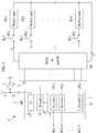
- FIG. 1 shows a block diagram of a configuration of an ECU and a BMS to which a communication method according to an exemplary embodiment is applied.
- the BMS 1 includes a micro control unit (MCU) 10, and the ECU 2 includes a MCU 20.
- MCU micro control unit
- the MCU 10 includes an input capture unit (ICU) 100, a digital input output (DIO) module 110, and a relay control module 120, and the MCU 20 includes a modulating signal generator 200 and an ICU 210.
- ICU input capture unit
- DIO digital input output
- relay control module 120 the MCU 20 includes a modulating signal generator 200 and an ICU 210.
- the BMS 1 is connected to the ECU 2 through a single line 3 and a CAN communication line 4.
- the BMS 1 may receive a relay control instruction from the ECU 2 according to a CAN communication using the CAN communication line 4, and may control the relay according to the relay control instruction.
- a relay control signal hereinafter, a modulating pulse signal
- the modulating pulse signal (MPS) is transmitted to the BMS 1 from the ECU 2 through the single line 3, and the BMS 1 may control the relay according to the modulating pulse signal (MPS) and may apply a first voltage level to the single line 3 as feedback by a period that corresponds to feedback information.
- the first voltage may be a ground level, but the present invention is not limited thereto, and the ECU 2 may be another level for recognizing a change of voltage.
- a first end of the single line 3 is connected to an external pin P1 of the ICU 100, and a second end of the single line 3 is connected to an external pin P2 of the modulating signal generator 200 and an external pin P3 of the ICU 210, so a half-duplex communication path between the BMS 1 and the ECU 2 is formed.
- the ICU 100 measures a frequency and a duty cycle of the modulating pulse signal (MPS) received through the single line 3.
- the ICU 100 may generate information (hereinafter, relay control information) on the frequency and the duty cycle of the measured modulating pulse signal (MPS), and may transmit the same to the relay control module 120.
- the relay control module 120 may control the switching operation of the corresponding relay based on the received relay control information.
- the relay control module 120 may open or close the relay that corresponds to the relay control information from among a plurality of relays according to the relay control information.
- the relay control module 120 may transmit information (hereinafter, relay control result information) for instructing a relay control result to the DIO module 110.
- the relay control result information may instruct the relay operated according to the relay control information from among a plurality of relays and a voltage change period determined according to a state of the corresponding relay.
- the relay control module 120 may also request transmission of the modulating pulse signal (MPS) to the BMS 1 from the ECU 2.
- MPS modulating pulse signal
- the relay control module 120 transmits relay control request information for requesting a modulating pulse signal (MPS) to the DIO module 110.
- the relay control request information may instruct a voltage change period determined according to the relay requiring relay control from among a plurality of relays and a state required of the corresponding relay.
- An example of the voltage change may be a pull-down.
- the DIO module 110 may control the switching operation of the switch 5 according to the received information and may generate a switching signal (SC) for changing a voltage at the single line 3 for a voltage change period according to relay control result information or relay control request information in the communication line 3.
- the DIO module 110 may transmit a switching signal (SC) to the switch 5 through an external pin P4.
- the switch 5 may perform a switching operation according to a level of the switching signal (SC).
- the switch 5 may be realized with a transistor operable in an electronic way according to the switching signal (SC) or a relay operable in a mechanical way.
- the modulating signal generator 200 may generate a modulating pulse signal (MPS) having a frequency and a duty cycle according to a control target relay and an instruction (hereinafter, a relay control instruction) on a state of the control target relay.
- the modulating signal generator 200 may apply a modulating pulse signal (MPS) to the communication line 3 through the external pin P2.
- a relay control instruction may be generated by the ECU 2.
- the ICU 210 is connected to the single line 3 through the external pin P3, and it may measure the frequency and the duty cycle of the single line 3 so as to detect a voltage change of the single line 3. For example, when the switch 5 is turned on and the single line 3 is grounded, the single line 3 is pulled down. For an On period of the switch 5, the single line 3 is in a pull-down state.
- the ICU 210 may measure the frequency and the duty cycle of the single line 3 to detect how long the single line 3 is in the pull-down state.
- the ICU 210 may generate information on a detection result, and the ECU 2 may recognize feedback information on the relay control result based on generated information, and may generate a relay control instruction in response to a relay control request.
- FIG. 2 shows a relay control module and a relay according to an exemplary embodiment.
- a battery device 6 includes a BMS 1 and a battery cell assembly 300, and a plurality of relays (400_1 to 400_n) for controlling power supply are electrically connected between the battery cell assembly 300 and a plurality of electrical loads (500_1 to 500_n).
- a plurality of battery cells of the battery cell assembly 300 are connected in series/parallel to each other to supply power.
- the battery cells may be electrically connected to the BMS 1 through a plurality of wires.
- the relay control module 120 includes a plurality of relay drivers (120_1 to 120_n), and the plurality of relay drivers (120_1 to 120_n) may respectively control the switching operation of the corresponding relay from among a plurality of relays (400_1 to 400_n).
- the BMS 1 may collect and analyze various information on the battery device including information on a plurality of battery cells, and may control charging and discharging of the battery device, balancing of battery cells, and a protection operation.
- the relay control module 120 controls the operation of the corresponding relay driver from among a plurality of relay drivers (120_1 to 120_n) based on relay control information received from the ICU 100.
- the relay control module 120 recognizes it as a control instruction for opening the first relay 400_1, and controls the relay driver 120_1 to generate an Off-level relay switching signal RLC1 for opening the relay 400_1.
- the relay driver 120_1 generates an Off-level relay switching signal RLC1, and the relay 400_1 is turned to Off and enters an open state according to the Off-level relay switching signal RLC1.
- the relay control module 120 controls the corresponding relay according to relay control information, and transmits relay control result information to the DIO module 110 so as to transmit a control result to the ECU 2 as a feedback. For example, when the relay 400_1 enters an open state, the relay control module 120 transmits relay control result information for instructing a period of T1[s] to the DIO module 110, and the DIO module 110 turns on the switch 5 for the period of T1[s]. The single line 3 is pulled down to a ground voltage for the period of T1[s].
- the relay control module 120 recognizes it as a control instruction for closing the first relay 400_1, and controls the relay driver 120_1 to generate an On-level relay switching signal RLC1 for closing the relay 400_1.
- the relay driver 120_1 generates an On-level relay switching signal RLC1
- the relay 400_1 is turned to On according to the On-level relay switching signal RLC1 and enters a closed state.
- the relay control module 120 transmits relay control result information for instructing the period of T2[s] to the DIO module 110, and the DIO module 110 turns on the switch 5 for the period of T2[s].
- the single line 3 is pulled down to the ground voltage for the period of T2[s].
- FIG. 3 shows a waveform diagram of a voltage change in a single line according to an exemplary embodiment.
- the modulating pulse signal (MPS) with the frequency of F1[Hz] and D1[%] is applied to the single line 3 in a MPS section PT1.
- a high level of the modulating pulse signal (MPS) is a power supply voltage level VCC for driving the MCU 10, and a low level is illustrated to be the ground, but the present invention is not limited, and the high level and the low level may be appropriately set depending on designs.
- the input capture unit (ICU) 100 measures the frequency and the duty cycle of the modulating pulse signal (MPS) received in the MPS section PT1, generates relay control information, and transmits the same to the relay control module 120, and the relay control module 120 controls the relay 400_1 to be in the open state, and transmits relay control result information for instructing T1[s] to the DIO module 110.
- MPS modulating pulse signal
- the DIO module 110 turns on the switch 5 for T1[s] to pull down the voltage at the single line 3 to the ground (GND).
- the ICU 210 measures the frequency and the duty cycle of the single line 3 to detect a pull-down period of the single line 3 and recognize a relay control result.
- Table 1 shows relay control information that corresponds to the frequency and the duty cycle of the modulating pulse signal received from the ECU 2, relay control information on states of the relays, and responses of the corresponding BMS 1.
- Table 1 Relay control information Modulating pulse signal BMS response Target State Frequency Duty cycle Pull-down period
- Relay 400_1 Open F1 [Hz] D1% T1[s]
- Relay 400_2 Open F2[Hz] D1% T3[s]
- the duty cycle when the state of each relay is open is D1 %
- the duty cycle when it is closed is D2 %
- the period (e.g., T1[s]) for instructing a time when a relay control result that is a BMS response is open may be different from the period (e.g., T2[s]) for instructing a time when it is closed.
- Table 1 shows an exemplary embodiment, the present invention is not limited thereto, and it is modifiable according to designs in a range of the frequency bandwidth and the duty cycle recognizable by the BMS 1 and the ECU 2.
- the relay control module 120 may generate relay control request information, and the DIO module 110 may control the switch 5 according to relay control request information and may pull down the single line 3.
- the relay control module 120 transmits relay control request information for instructing Tm[s] to the DIO module 110, and the DIO module 110 turns on the switch 5 for Tm[s] according to relay control request information.
- the ICU 210 measures the frequency and the duty cycle of the single line 3 to detect the pull-down period Tm[s] of the single line 3, and outputs a detection result to the ECU 2.
- the ECU 2 may generate a relay control instruction for opening the relay 400_1 according to a detection result, and may transmit the same to the modulating signal generator 200.
- the relay control module 120 When the relay control module 120 requests relay control, it may transmit trigger information for notifying it to the DIO module 110 before relay control request information.
- the DIO module 110 may control the switching operation of the switch 5 according to trigger information to control the voltage waveform of the single line 3 to have a specific frequency and duty cycle.
- the ICU 210 may recognize that relay control request information will be transmitted when measuring the specific frequency and the duty cycle through the single line 3.
- the frequency and the duty cycle of the single line 3 measured after recognition correspond to relay control request information, and the ICU 210 detects Tm[s] that corresponds to relay control request information, and outputs a detection result that corresponds to relay control request information to the ECU 2.
- the ECU 2 may generate a relay control instruction according to a detection result and may transmit the same to the ICU 200.
- normal relay control is possible when there is a CAN communication problem between the BMS and the higher-level ECU.
Landscapes
- Engineering & Computer Science (AREA)
- Signal Processing (AREA)
- Computer Networks & Wireless Communication (AREA)
- Physics & Mathematics (AREA)
- Spectroscopy & Molecular Physics (AREA)
- Power Engineering (AREA)
- Quality & Reliability (AREA)
- Electric Propulsion And Braking For Vehicles (AREA)
- Cable Transmission Systems, Equalization Of Radio And Reduction Of Echo (AREA)
- Bidirectional Digital Transmission (AREA)
- Relay Circuits (AREA)
Abstract
Description
- This application claims priority to and the benefit of Korean Patent Application No.
10-2019-0007629 - The present disclosure relates to a battery manager system (BMS), an electronic control unit (ECU), and a communication method between a BMS and an ECU.
- In a vehicle in a normal state, a battery management system (BMS) of a battery installed in the vehicle receives a relay control instruction from an electronic control unit (ECU) of the vehicle through a CAN communication, analyzes the received relay control instruction, and controls a relay.
- When the CAN communication between the higher-level ECU and the BMS has a defect, the higher-level ECU loses a control right to the relay, and in correspondence to this, the BMS forcibly opens the relay regardless of the higher-level ECU, and has the battery system enter a safe state.
- This may prevent the battery system from being abnormally controlled, but the vehicle fails to receive power from the battery system. The vehicle may not drive normally or may drive but in a limited way because the power supply from the battery system is blocked. A user of the vehicle may then feel uneasy or fall into risky situations.
- The present invention has been made in an effort to provide a BMS and an ECU for providing communication between the ECU and the BMS when there is a CAN communication disruption between the ECU and the BMS, and a communication method therebetween.
- An exemplary embodiment of the present invention provides a battery manager system (BMS) connected to an electronic control unit (ECU) by CAN communication and half-duplex communication through a single line, including: an input capture unit (ICU) for, when the CAN communication has a defect, measuring a frequency and a duty cycle of a modulating pulse signal through the single line, and generating relay control information; a relay control module for generating a relay control signal for controlling a switching operation of a corresponding relay from among a plurality of relays based on the relay control information, and generating relay control result information for instructing a control result of the corresponding relay; and a digital input output (DIO) module for changing a voltage at the single line so as to transmit relay control result information to the ECU for a period based on the relay control result information, wherein the plurality of relays may be electrically connected between a battery device including the BMS and an electrical load.
- The relay control module may generate relay control request information and may transmit the relay control request information to the DIO module, and the DIO module may change a voltage at the single line according to the relay control request information.
- The relay control module may include a plurality of relay drivers for transmitting a plurality of relay control signals to the plurality of relays, and the plurality of relays may be respectively opened or closed according to a corresponding relay control signal from among the plurality of relay control signals.
- The relay control module may control a corresponding relay from among a plurality of relays according to the relay control information, and may generate the relay control result information for instructing another period according to a state of the corresponding relay.
- A frequency of the modulating pulse signal may be different for the plurality of relays, and a duty cycle of the modulating pulse signal may be different according to respective states of the plurality of relays.
- Another embodiment of the present invention provides an electronic control unit (ECU) connected to a battery manager system (BMS) by CAN communication and half-duplex communication through a single line, including: a modulating signal generator for, when the CAN communication is bad, generating a modulating pulse signal with a frequency and a duty cycle according to a relay control instruction on a control target relay from among a plurality of relays and a state of the control target relay; and an input capture unit (ICU) for detecting a change of voltage at the single line by measuring a frequency and a duty cycle of the single line, wherein the plurality of relays may be respectively electrically connected between a battery device of the BMS and a corresponding electrical load.
- The ICU may measure a frequency and a duty cycle of the single line, and may output the relay control request information to the ECU when detecting a change of voltage of the single line for a period that corresponds to relay control request information.
- The ECU may generate a relay control instruction according to the relay control request information, and may output the same to the modulating signal generator.
- Yet another embodiment of the present invention provides a communication method between an electronic control unit (ECU) and a battery manager system (BMS) connected by CAN communication and half-duplex communication through a single line, including: generating a modulating pulse signal with a frequency and a duty cycle according to a relay control instruction on a control target relay from among a plurality of relays and a state of the control target relay, by the ECU, when the CAN communication has a defect; generating relay control information by measuring a frequency and a duty cycle of the modulating pulse signal by the BMS; generating a relay control signal for controlling a switching operation of a relay from among a plurality of relays based on the relay control information by the BMS; generating relay control result information for instructing a control result of the corresponding relay by the BMS; changing a voltage of the single line by the BMS so as to transmit relay control result information to the ECU for a period based on the relay control result information; and detecting a change of the voltage at the single line by measuring a frequency and a duty cycle of the single line by the ECU. The plurality of relays may be electrically connected between a battery device including the BMS and an electrical load.
- The communication method may further include: changing the voltage at the single line according to relay control request information by the BMS; measuring a frequency and a duty cycle of the single line, and detecting the change of the voltage at the single line for a period that corresponds to the relay control request information by the ECU; and generating a relay control instruction based on the relay control request information by the ECU when the change of the voltage at the single line is detected.
- The BMS and the ECU for providing communication between the ECU and the BMS even when there is a CAN communication problem between the ECU and the BMS, and a communication method therebetween, are provided.
-
-
FIG. 1 shows a block diagram of a configuration of an ECU and a BMS to which a communication method according to an exemplary embodiment is applied. -
FIG. 2 shows a relay control module and a relay according to an exemplary embodiment. -
FIG. 3 shows a waveform diagram of a voltage change in a single line according to an exemplary embodiment. - A communication method according to an exemplary embodiment of the present invention is a single line communication method according to a half-duplex scheme using a pulse signal (hereinafter, a modulated pulse signal) obtained by modulating a frequency and a duty cycle between the BMS and the ECU.
- First, the ECU may transmit the pulse signal with the modulated frequency and the duty cycle to the BMS so as to instruct a switching operation of a control target relay from among a plurality of relays. The BMS may control the switching operation of the corresponding relay according to the modulating pulse signal received from the ECU. The BMS may control a first voltage change period to a communication line and may feed back to the ECU so as to instruct a switching result of the corresponding relay according to a modulating pulse signal. A state of the relay is one of open and closed, and changing the state of the relay is referred to as a switching operation.
- In the following detailed description, only certain exemplary embodiments of the present invention have been shown and described, simply by way of illustration. As those skilled in the art would realize, the described embodiments may be modified in various different ways, all without departing from the spirit or scope of the present invention. Accordingly, the drawings and description are to be regarded as illustrative in nature and not restrictive. Like reference numerals designate like elements throughout the specification.
-
FIG. 1 shows a block diagram of a configuration of an ECU and a BMS to which a communication method according to an exemplary embodiment is applied. - As shown in
FIG. 1 , theBMS 1 includes a micro control unit (MCU) 10, and theECU 2 includes aMCU 20. - The MCU 10 includes an input capture unit (ICU) 100, a digital input output (DIO)
module 110, and arelay control module 120, and theMCU 20 includes a modulatingsignal generator 200 and an ICU 210. - The
BMS 1 is connected to theECU 2 through asingle line 3 and a CAN communication line 4. TheBMS 1 may receive a relay control instruction from theECU 2 according to a CAN communication using the CAN communication line 4, and may control the relay according to the relay control instruction. However, in the case of a CAN communication defect because of a problem in the CAN communication line 4, etc., it may receive a relay control signal (hereinafter, a modulating pulse signal) from theECU 2 according to a half-duplex communication using thesingle line 3. - The modulating pulse signal (MPS) is transmitted to the
BMS 1 from theECU 2 through thesingle line 3, and theBMS 1 may control the relay according to the modulating pulse signal (MPS) and may apply a first voltage level to thesingle line 3 as feedback by a period that corresponds to feedback information. In an exemplary embodiment, the first voltage may be a ground level, but the present invention is not limited thereto, and theECU 2 may be another level for recognizing a change of voltage. - A first end of the
single line 3 is connected to an external pin P1 of theICU 100, and a second end of thesingle line 3 is connected to an external pin P2 of the modulatingsignal generator 200 and an external pin P3 of theICU 210, so a half-duplex communication path between theBMS 1 and theECU 2 is formed. - The ICU 100 measures a frequency and a duty cycle of the modulating pulse signal (MPS) received through the
single line 3. The ICU 100 may generate information (hereinafter, relay control information) on the frequency and the duty cycle of the measured modulating pulse signal (MPS), and may transmit the same to therelay control module 120. - The
relay control module 120 may control the switching operation of the corresponding relay based on the received relay control information. Therelay control module 120 may open or close the relay that corresponds to the relay control information from among a plurality of relays according to the relay control information. After completing a relay control operation according to the relay control information, therelay control module 120 may transmit information (hereinafter, relay control result information) for instructing a relay control result to theDIO module 110. The relay control result information may instruct the relay operated according to the relay control information from among a plurality of relays and a voltage change period determined according to a state of the corresponding relay. Therelay control module 120 may also request transmission of the modulating pulse signal (MPS) to theBMS 1 from theECU 2. For example, therelay control module 120 transmits relay control request information for requesting a modulating pulse signal (MPS) to theDIO module 110. The relay control request information may instruct a voltage change period determined according to the relay requiring relay control from among a plurality of relays and a state required of the corresponding relay. An example of the voltage change may be a pull-down. - After receiving relay control result information or relay control request information, the
DIO module 110 may control the switching operation of theswitch 5 according to the received information and may generate a switching signal (SC) for changing a voltage at thesingle line 3 for a voltage change period according to relay control result information or relay control request information in thecommunication line 3. TheDIO module 110 may transmit a switching signal (SC) to theswitch 5 through an external pin P4. Theswitch 5 may perform a switching operation according to a level of the switching signal (SC). Theswitch 5 may be realized with a transistor operable in an electronic way according to the switching signal (SC) or a relay operable in a mechanical way. - The modulating
signal generator 200 may generate a modulating pulse signal (MPS) having a frequency and a duty cycle according to a control target relay and an instruction (hereinafter, a relay control instruction) on a state of the control target relay. The modulatingsignal generator 200 may apply a modulating pulse signal (MPS) to thecommunication line 3 through the external pin P2. A relay control instruction may be generated by theECU 2. - The
ICU 210 is connected to thesingle line 3 through the external pin P3, and it may measure the frequency and the duty cycle of thesingle line 3 so as to detect a voltage change of thesingle line 3. For example, when theswitch 5 is turned on and thesingle line 3 is grounded, thesingle line 3 is pulled down. For an On period of theswitch 5, thesingle line 3 is in a pull-down state. TheICU 210 may measure the frequency and the duty cycle of thesingle line 3 to detect how long thesingle line 3 is in the pull-down state. TheICU 210 may generate information on a detection result, and theECU 2 may recognize feedback information on the relay control result based on generated information, and may generate a relay control instruction in response to a relay control request. -
FIG. 2 shows a relay control module and a relay according to an exemplary embodiment. - In
FIG. 2 , a battery device 6 includes aBMS 1 and abattery cell assembly 300, and a plurality of relays (400_1 to 400_n) for controlling power supply are electrically connected between thebattery cell assembly 300 and a plurality of electrical loads (500_1 to 500_n). - A plurality of battery cells of the
battery cell assembly 300 are connected in series/parallel to each other to supply power. The battery cells may be electrically connected to theBMS 1 through a plurality of wires. - As shown in
FIG. 2 , therelay control module 120 includes a plurality of relay drivers (120_1 to 120_n), and the plurality of relay drivers (120_1 to 120_n) may respectively control the switching operation of the corresponding relay from among a plurality of relays (400_1 to 400_n). TheBMS 1 may collect and analyze various information on the battery device including information on a plurality of battery cells, and may control charging and discharging of the battery device, balancing of battery cells, and a protection operation. - The
relay control module 120 controls the operation of the corresponding relay driver from among a plurality of relay drivers (120_1 to 120_n) based on relay control information received from theICU 100. - For example, when the relay control information instructs that the modulating pulse signal (MPS) has a frequency F1[Hz] and D1[%], the
relay control module 120 recognizes it as a control instruction for opening the first relay 400_1, and controls the relay driver 120_1 to generate an Off-level relay switching signal RLC1 for opening the relay 400_1. The relay driver 120_1 generates an Off-level relay switching signal RLC1, and the relay 400_1 is turned to Off and enters an open state according to the Off-level relay switching signal RLC1. - The
relay control module 120 controls the corresponding relay according to relay control information, and transmits relay control result information to theDIO module 110 so as to transmit a control result to theECU 2 as a feedback. For example, when the relay 400_1 enters an open state, therelay control module 120 transmits relay control result information for instructing a period of T1[s] to theDIO module 110, and theDIO module 110 turns on theswitch 5 for the period of T1[s]. Thesingle line 3 is pulled down to a ground voltage for the period of T1[s]. - In another way, when the relay control information instructs that the modulating pulse signal (MPS) has the frequency of F1[Hz] and D2[%], the
relay control module 120 recognizes it as a control instruction for closing the first relay 400_1, and controls the relay driver 120_1 to generate an On-level relay switching signal RLC1 for closing the relay 400_1. The relay driver 120_1 generates an On-level relay switching signal RLC1, and the relay 400_1 is turned to On according to the On-level relay switching signal RLC1 and enters a closed state. - When the relay 400_1 enters the closed state, the
relay control module 120 transmits relay control result information for instructing the period of T2[s] to theDIO module 110, and theDIO module 110 turns on theswitch 5 for the period of T2[s]. Thesingle line 3 is pulled down to the ground voltage for the period of T2[s]. -
FIG. 3 shows a waveform diagram of a voltage change in a single line according to an exemplary embodiment. - As shown in
FIG. 3 , the modulating pulse signal (MPS) with the frequency of F1[Hz] and D1[%] is applied to thesingle line 3 in a MPS section PT1. A high level of the modulating pulse signal (MPS) is a power supply voltage level VCC for driving theMCU 10, and a low level is illustrated to be the ground, but the present invention is not limited, and the high level and the low level may be appropriately set depending on designs. - For a predetermined period PT2, the input capture unit (ICU) 100 measures the frequency and the duty cycle of the modulating pulse signal (MPS) received in the MPS section PT1, generates relay control information, and transmits the same to the
relay control module 120, and therelay control module 120 controls the relay 400_1 to be in the open state, and transmits relay control result information for instructing T1[s] to theDIO module 110. - For a BMS response period PT3, the
DIO module 110 turns on theswitch 5 for T1[s] to pull down the voltage at thesingle line 3 to the ground (GND). - For the period PT2 and the BMS response period PT3 after the MPS section PT1 ends, the
ICU 210 measures the frequency and the duty cycle of thesingle line 3 to detect a pull-down period of thesingle line 3 and recognize a relay control result. - Table 1 shows relay control information that corresponds to the frequency and the duty cycle of the modulating pulse signal received from the
ECU 2, relay control information on states of the relays, and responses of thecorresponding BMS 1.(Table 1) Relay control information Modulating pulse signal BMS response Target State Frequency Duty cycle Pull-down period Relay 400_1 Open F1 [Hz] D1% T1[s] Relay 400_1 Closed F1[Hz] D2% T2[s] Relay 400_2 Open F2[Hz] D1% T3[s] Relay 400_2 Closed F2[Hz] D2% T4[s] ... Relay 400_n Open Fn[Hz] D1% Tk-1[s] Relay 400_n Closed Fn[Hz] D2% Tk[s] - In Table 1, a reciprocal number of a minimum frequency from among frequencies F1 to Fn must be smaller than the minimum value of the pull-down periods T1 to Tk. This is to distinguish information transmitted/received through the
single line 3. - As can be known from Table 1, specific frequencies are allocated to a plurality of relays, the duty cycle when the state of each relay is open is D1 %, the duty cycle when it is closed is D2 %, and the period (e.g., T1[s]) for instructing a time when a relay control result that is a BMS response is open may be different from the period (e.g., T2[s]) for instructing a time when it is closed.
- Table 1 shows an exemplary embodiment, the present invention is not limited thereto, and it is modifiable according to designs in a range of the frequency bandwidth and the duty cycle recognizable by the
BMS 1 and theECU 2. - The
relay control module 120 may generate relay control request information, and theDIO module 110 may control theswitch 5 according to relay control request information and may pull down thesingle line 3. - For example, the
relay control module 120 transmits relay control request information for instructing Tm[s] to theDIO module 110, and theDIO module 110 turns on theswitch 5 for Tm[s] according to relay control request information. TheICU 210 measures the frequency and the duty cycle of thesingle line 3 to detect the pull-down period Tm[s] of thesingle line 3, and outputs a detection result to theECU 2. TheECU 2 may generate a relay control instruction for opening the relay 400_1 according to a detection result, and may transmit the same to the modulatingsignal generator 200. - When the
relay control module 120 requests relay control, it may transmit trigger information for notifying it to theDIO module 110 before relay control request information. TheDIO module 110 may control the switching operation of theswitch 5 according to trigger information to control the voltage waveform of thesingle line 3 to have a specific frequency and duty cycle. TheICU 210 may recognize that relay control request information will be transmitted when measuring the specific frequency and the duty cycle through thesingle line 3. The frequency and the duty cycle of thesingle line 3 measured after recognition correspond to relay control request information, and theICU 210 detects Tm[s] that corresponds to relay control request information, and outputs a detection result that corresponds to relay control request information to theECU 2. TheECU 2 may generate a relay control instruction according to a detection result and may transmit the same to theICU 200. - As described, according to an exemplary embodiment of the present invention, normal relay control is possible when there is a CAN communication problem between the BMS and the higher-level ECU.
- While this invention has been described in connection with what is presently considered to be practical exemplary embodiments, it is to be understood that the invention is not limited to the disclosed embodiments, but, on the contrary, is intended to cover various modifications and equivalent arrangements included within the spirit and scope of the appended claims.
Claims (11)
- A battery manager system (BMS) connected to an electronic control unit (ECU) by CAN communication and half-duplex communication through a single line, comprising:an input capture unit (ICU) for, when the CAN communication has a defect, measuring a frequency and a duty cycle of a modulating pulse signal through the single line, and generating relay control information;a relay control module for generating a relay control signal for controlling a switching operation of a corresponding relay from among a plurality of relays based on the relay control information, and generating relay control result information for instructing a control result of the corresponding relay; anda digital input output (DIO) module for changing a voltage at the single line so as to transmit relay control result information to the ECU for a period based on the relay control result information,wherein the plurality of relays are electrically connected between a battery device including the BMS and an electrical load.
- The BMS of claim 1, wherein
the relay control module generates relay control request information and transmits the relay control request information to the DIO module, and
the DIO module changes a voltage at the single line according to the relay control request information. - The BMS of claim 1, wherein
the relay control module includes a plurality of relay drivers for transmitting a plurality of relay control signals to the plurality of relays, and the plurality of relays are respectively opened or closed according to a corresponding relay control signal from among the plurality of relay control signals. - The BMS of claim 1, wherein
the relay control module controls a corresponding relay from among a plurality of relays according to the relay control information, and generates the relay control result information for instructing another period according to a state of the corresponding relay. - The BMS of claim 1, wherein
a frequency of the modulating pulse signal is different for the plurality of relays, and
a duty cycle of the modulating pulse signal is different according to respective states of the plurality of relays. - An electronic control unit (ECU) connected to a battery manager system (BMS) by CAN communication and half-duplex communication through a single line, comprising:a modulating signal generator for, when the CAN communication is bad, generating a modulating pulse signal with a frequency and a duty cycle according to a relay control instruction on a control target relay from among a plurality of relays and a state of the control target relay; andan input capture unit (ICU) for detecting a change of voltage at the single line by measuring a frequency and a duty cycle of the single line,wherein the plurality of relays are respectively electrically connected between a battery device of the BMS and a corresponding electrical load.
- The ECU of claim 6, wherein
the ICU measures a frequency and a duty cycle of the single line, and outputs the relay control request information to the ECU when detecting a change of voltage of the single line for a period that corresponds to relay control request information. - The ECU of claim 7, wherein
the ECU generates a relay control instruction according to the relay control request information, and outputs the same to the modulating signal generator. - The ECU of claim 6, wherein
the modulating pulse signal has different frequencies for the respective relays, and
the modulating pulse signal has different duty cycles for states of the respective relays. - A communication method between an electronic control unit (ECU) and a battery manager system (BMS) connected by CAN communication and half-duplex communication through a single line, comprising:generating a modulating pulse signal with a frequency and a duty cycle according to a relay control instruction on a control target relay from among a plurality of relays and a state of the control target relay, by the ECU, when the CAN communication has a defect;generating relay control information by measuring a frequency and a duty cycle of the modulating pulse signal by the BMS;generating a relay control signal for controlling a switching operation of a relay from among a plurality of relays based on the relay control information by the BMS;generating relay control result information for instructing a control result of the corresponding relay by the BMS;changing a voltage of the single line by the BMS so as to transmit relay control result information to the ECU for a period based on the relay control result information; anddetecting a change of the voltage at the single line by measuring a frequency and a duty cycle of the single line by the ECU,wherein the plurality of relays are electrically connected between a battery device including the BMS and an electrical load.
- The communication method of claim 10, further comprising:changing the voltage at the single line according to relay control request information by the BMS;measuring a frequency and a duty cycle of the single line, and detecting the change of the voltage at the single line for a period that corresponds to the relay control request information by the ECU; andgenerating a relay control instruction based on the relay control request information by the ECU when the change of the voltage at the single line is detected.
Applications Claiming Priority (2)
| Application Number | Priority Date | Filing Date | Title |
|---|---|---|---|
| KR1020190007629A KR102676149B1 (en) | 2019-01-21 | 2019-01-21 | Battery Manager System, Electronic Control Unit, and Communication method between Battery Manager System and Electronic Control Unit |
| PCT/KR2020/001028 WO2020153719A1 (en) | 2019-01-21 | 2020-01-21 | Battery manager system (bms), electronic control unit (ecu), and communication method between bms and ecu |
Publications (3)
| Publication Number | Publication Date |
|---|---|
| EP3855684A1 true EP3855684A1 (en) | 2021-07-28 |
| EP3855684A4 EP3855684A4 (en) | 2021-11-10 |
| EP3855684B1 EP3855684B1 (en) | 2024-10-02 |
Family
ID=71736342
Family Applications (1)
| Application Number | Title | Priority Date | Filing Date |
|---|---|---|---|
| EP20745933.0A Active EP3855684B1 (en) | 2019-01-21 | 2020-01-21 | Battery manager system (bms), electronic control unit (ecu), and communication method between bms and ecu |
Country Status (8)
| Country | Link |
|---|---|
| US (1) | US11831463B2 (en) |
| EP (1) | EP3855684B1 (en) |
| JP (1) | JP7099796B2 (en) |
| KR (1) | KR102676149B1 (en) |
| CN (1) | CN112823497B (en) |
| ES (1) | ES2991717T3 (en) |
| HU (1) | HUE068795T2 (en) |
| WO (1) | WO2020153719A1 (en) |
Families Citing this family (4)
| Publication number | Priority date | Publication date | Assignee | Title |
|---|---|---|---|---|
| KR102676149B1 (en) * | 2019-01-21 | 2024-06-17 | 주식회사 엘지에너지솔루션 | Battery Manager System, Electronic Control Unit, and Communication method between Battery Manager System and Electronic Control Unit |
| JP7310728B2 (en) * | 2020-06-17 | 2023-07-19 | トヨタ自動車株式会社 | Battery pack for electric vehicles |
| CN117831150B (en) * | 2023-12-28 | 2026-05-05 | 北京经纬恒润科技股份有限公司 | A vehicle-mounted communication method and system, electronic device, and storage medium |
| KR20250132055A (en) * | 2024-02-28 | 2025-09-04 | 삼성에스디아이 주식회사 | Bi-directional communication based control appratus and system, bi-directional communication inerface |
Family Cites Families (33)
| Publication number | Priority date | Publication date | Assignee | Title |
|---|---|---|---|---|
| JP2004328488A (en) | 2003-04-25 | 2004-11-18 | Denso Corp | Vehicle communication system |
| SE533636C2 (en) * | 2004-10-25 | 2010-11-16 | Xinshu Man L L C | Device for bus connection in CAN system |
| US8213321B2 (en) * | 2007-02-01 | 2012-07-03 | Deere & Company | Controller area network condition monitoring and bus health on in-vehicle communications networks |
| JP5028250B2 (en) | 2007-12-26 | 2012-09-19 | 本田技研工業株式会社 | Redundant communication system |
| CN102386637B (en) * | 2010-09-03 | 2013-11-13 | 凹凸电子(武汉)有限公司 | Battery management system and method for controlling vehicle |
| JP4788804B2 (en) * | 2009-06-01 | 2011-10-05 | 株式会社デンソー | Electronic control unit |
| JP5582748B2 (en) | 2009-09-17 | 2014-09-03 | 株式会社ケーヒン | Electronic control device for vehicle |
| KR101199320B1 (en) | 2010-02-25 | 2012-11-09 | (주)모토닉 | Unit for driving oil pump for plug-in hybrid vehicle |
| KR101184752B1 (en) | 2010-06-03 | 2012-09-20 | 정윤이 | Battery package and charging method of battery package |
| JP5741480B2 (en) | 2012-02-17 | 2015-07-01 | 株式会社オートネットワーク技術研究所 | Communication system, relay device, and power supply control method |
| KR20130137975A (en) | 2012-06-08 | 2013-12-18 | 넥스콘 테크놀러지 주식회사 | Method and apparatus for controlling communication of battery management system |
| US10464507B2 (en) * | 2013-03-07 | 2019-11-05 | Samsung Sdi Co., Ltd. | Battery management system and switching method thereof |
| US9537328B2 (en) * | 2013-05-23 | 2017-01-03 | Samsung Sdi Co., Ltd. | Battery management system and method of driving the same |
| CN103809476A (en) * | 2014-02-24 | 2014-05-21 | 中国第一汽车股份有限公司 | Dynamic management method for IDs of module control units of distributed battery management system |
| KR20220119761A (en) * | 2014-03-21 | 2022-08-30 | 레오나르드 진스버그 | Medical services tracking system and method |
| US9851772B2 (en) | 2014-08-22 | 2017-12-26 | Linear Technology Corporation | 1-wire bus PD detection and classification scheme for ethernet PoDL |
| KR101526817B1 (en) | 2014-09-25 | 2015-06-09 | 김황근 | Module type storage battery monitoring system connected with can communication |
| CN104354596B (en) | 2014-10-31 | 2016-09-07 | 安徽江淮汽车股份有限公司 | A kind of battery bag safety detection circuit and detection method |
| CN105730258B (en) | 2014-12-10 | 2019-07-26 | 比亚迪股份有限公司 | Automobile ignition control system and automobile |
| FR3037406B1 (en) * | 2015-06-15 | 2017-06-02 | Renault Sas | ELECTRICAL SYSTEM COMPRISING A CIRCUIT FOR DETECTING AN ELECTRIC ISOLATION FAULT |
| CN108028600B (en) | 2015-07-08 | 2022-03-08 | 派更半导体公司 | Switched Capacitor Power Converters |
| KR101714481B1 (en) | 2015-08-25 | 2017-03-09 | 현대자동차주식회사 | Communication network, vehicle including the same, and control method for the same |
| JP6603085B2 (en) | 2015-09-04 | 2019-11-06 | 株式会社エンビジョンAescジャパン | Vehicle power supply device and vehicle control device |
| US20170117532A1 (en) * | 2015-10-22 | 2017-04-27 | Boston-Power, Inc. | Detecting cell over-temperature in a battery cell |
| KR101927175B1 (en) * | 2016-08-30 | 2019-03-12 | 현대자동차 주식회사 | Vehicle system, battery system and control method thereof |
| KR102345506B1 (en) | 2017-01-24 | 2021-12-29 | 삼성에스디아이 주식회사 | Battery pack, control method of charging the same, and vehicle comprisin the same |
| KR20190007629A (en) | 2017-07-13 | 2019-01-23 | 한국과학기술원 | Book management system using rfid tag and reader |
| KR102256601B1 (en) * | 2017-11-07 | 2021-06-02 | 주식회사 엘지에너지솔루션 | BMS Wake-up Apparatus, BMS and Battery pack including the same |
| KR102442474B1 (en) * | 2018-11-30 | 2022-09-14 | 주식회사 엘지에너지솔루션 | Battery cell resistance measurement device and method |
| KR102676149B1 (en) * | 2019-01-21 | 2024-06-17 | 주식회사 엘지에너지솔루션 | Battery Manager System, Electronic Control Unit, and Communication method between Battery Manager System and Electronic Control Unit |
| GB201905732D0 (en) * | 2019-04-24 | 2019-06-05 | Proqr Therapeutics Ii Bv | RNA editing inhibitors and methods of use |
| KR102753091B1 (en) * | 2020-02-26 | 2025-01-09 | 주식회사 엘지에너지솔루션 | Apparatus and method for providing battery information |
| KR20230102317A (en) * | 2021-12-30 | 2023-07-07 | 에스케이온 주식회사 | A management system and the communication network control method thereof for a battery management system |
-
2019
- 2019-01-21 KR KR1020190007629A patent/KR102676149B1/en active Active
-
2020
- 2020-01-21 ES ES20745933T patent/ES2991717T3/en active Active
- 2020-01-21 EP EP20745933.0A patent/EP3855684B1/en active Active
- 2020-01-21 JP JP2021516765A patent/JP7099796B2/en active Active
- 2020-01-21 HU HUE20745933A patent/HUE068795T2/en unknown
- 2020-01-21 US US17/282,867 patent/US11831463B2/en active Active
- 2020-01-21 WO PCT/KR2020/001028 patent/WO2020153719A1/en not_active Ceased
- 2020-01-21 CN CN202080005618.0A patent/CN112823497B/en active Active
Also Published As
| Publication number | Publication date |
|---|---|
| CN112823497A (en) | 2021-05-18 |
| ES2991717T3 (en) | 2024-12-04 |
| EP3855684B1 (en) | 2024-10-02 |
| WO2020153719A1 (en) | 2020-07-30 |
| HUE068795T2 (en) | 2025-01-28 |
| US20210351953A1 (en) | 2021-11-11 |
| US11831463B2 (en) | 2023-11-28 |
| JP2022502302A (en) | 2022-01-11 |
| EP3855684A4 (en) | 2021-11-10 |
| JP7099796B2 (en) | 2022-07-12 |
| KR102676149B1 (en) | 2024-06-17 |
| KR20200090514A (en) | 2020-07-29 |
| CN112823497B (en) | 2022-09-13 |
Similar Documents
| Publication | Publication Date | Title |
|---|---|---|
| EP3855684B1 (en) | Battery manager system (bms), electronic control unit (ecu), and communication method between bms and ecu | |
| CN104626997A (en) | Electric vehicle battery contactor switch monitoring system | |
| EP3104525A1 (en) | Load-driving circuit | |
| US12301042B2 (en) | Error detecting method of charging switch unit and battery system using the same | |
| US12533986B2 (en) | Apparatus and application for predicting discharge of battery | |
| US10953862B2 (en) | Method for operating a parking brake and control device for operating a parking brake | |
| CN102739141B (en) | Motor driving device | |
| CN112248866A (en) | An electric vehicle charging control device and method | |
| CN111959344A (en) | Battery management system, control method and vehicle | |
| US11411414B2 (en) | Power supply device that performs malfunctioned determination | |
| KR20200088153A (en) | apparatus for checking current sensor, and battery pack including the apparatus | |
| US12083898B2 (en) | Battery system | |
| US20220118856A1 (en) | High voltage circuit and method for controlling a contactor in electric vehicles | |
| KR20210041282A (en) | Charge/discharge switch control method and battery system whrer the method is applied | |
| CN111381155B (en) | Method and system for diagnosing the status of a contactor | |
| CN114175434B (en) | Battery pack power-off device and battery pack power-off method | |
| KR102673513B1 (en) | Battery management system and bms control system | |
| AU687187B2 (en) | Process for the low-energy interrogation of binary states over long lines | |
| EP3982139A1 (en) | Circuit diagnosis device and battery pack including same | |
| CN221726087U (en) | Relay conversion board and relay detection device | |
| EP0651302B1 (en) | Interface for devices controlled by microcontrollers and/or microprocessors | |
| KR100325159B1 (en) | Using Optical Transmission System a Device for ElectroMagnetic Susceptibility | |
| KR100417902B1 (en) | Apparatus for detecting temporary opening of battery using scr | |
| KR20230135715A (en) | Battery system capable of pack relay diagnosis and vehicle comprising the same | |
| KR101664564B1 (en) | Source supply apparatus for charging and Method for controlling the same |
Legal Events
| Date | Code | Title | Description |
|---|---|---|---|
| STAA | Information on the status of an ep patent application or granted ep patent |
Free format text: STATUS: THE INTERNATIONAL PUBLICATION HAS BEEN MADE |
|
| PUAI | Public reference made under article 153(3) epc to a published international application that has entered the european phase |
Free format text: ORIGINAL CODE: 0009012 |
|
| STAA | Information on the status of an ep patent application or granted ep patent |
Free format text: STATUS: REQUEST FOR EXAMINATION WAS MADE |
|
| 17P | Request for examination filed |
Effective date: 20210421 |
|
| AK | Designated contracting states |
Kind code of ref document: A1 Designated state(s): AL AT BE BG CH CY CZ DE DK EE ES FI FR GB GR HR HU IE IS IT LI LT LU LV MC MK MT NL NO PL PT RO RS SE SI SK SM TR |
|
| A4 | Supplementary search report drawn up and despatched |
Effective date: 20211008 |
|
| RIC1 | Information provided on ipc code assigned before grant |
Ipc: H04L 5/16 20060101ALN20211004BHEP Ipc: H04L 12/40 20060101AFI20211004BHEP |
|
| RAP1 | Party data changed (applicant data changed or rights of an application transferred) |
Owner name: LG ENERGY SOLUTION LTD. |
|
| RAP3 | Party data changed (applicant data changed or rights of an application transferred) |
Owner name: LG ENERGY SOLUTION, LTD. |
|
| DAV | Request for validation of the european patent (deleted) | ||
| DAX | Request for extension of the european patent (deleted) | ||
| STAA | Information on the status of an ep patent application or granted ep patent |
Free format text: STATUS: EXAMINATION IS IN PROGRESS |
|
| 17Q | First examination report despatched |
Effective date: 20230220 |
|
| GRAP | Despatch of communication of intention to grant a patent |
Free format text: ORIGINAL CODE: EPIDOSNIGR1 |
|
| STAA | Information on the status of an ep patent application or granted ep patent |
Free format text: STATUS: GRANT OF PATENT IS INTENDED |
|
| RIC1 | Information provided on ipc code assigned before grant |
Ipc: H04L 5/16 20060101ALN20240426BHEP Ipc: H04L 12/40 20060101AFI20240426BHEP |
|
| INTG | Intention to grant announced |
Effective date: 20240514 |
|
| P01 | Opt-out of the competence of the unified patent court (upc) registered |
Free format text: CASE NUMBER: APP_33837/2024 Effective date: 20240606 |
|
| GRAS | Grant fee paid |
Free format text: ORIGINAL CODE: EPIDOSNIGR3 |
|
| GRAA | (expected) grant |
Free format text: ORIGINAL CODE: 0009210 |
|
| STAA | Information on the status of an ep patent application or granted ep patent |
Free format text: STATUS: THE PATENT HAS BEEN GRANTED |
|
| AK | Designated contracting states |
Kind code of ref document: B1 Designated state(s): AL AT BE BG CH CY CZ DE DK EE ES FI FR GB GR HR HU IE IS IT LI LT LU LV MC MK MT NL NO PL PT RO RS SE SI SK SM TR |
|
| REG | Reference to a national code |
Ref country code: GB Ref legal event code: FG4D |
|
| REG | Reference to a national code |
Ref country code: CH Ref legal event code: EP |
|
| REG | Reference to a national code |
Ref country code: DE Ref legal event code: R096 Ref document number: 602020038699 Country of ref document: DE |
|
| REG | Reference to a national code |
Ref country code: IE Ref legal event code: FG4D |
|
| REG | Reference to a national code |
Ref country code: ES Ref legal event code: FG2A Ref document number: 2991717 Country of ref document: ES Kind code of ref document: T3 Effective date: 20241204 |
|
| REG | Reference to a national code |
Ref country code: LT Ref legal event code: MG9D |
|
| REG | Reference to a national code |
Ref country code: HU Ref legal event code: AG4A Ref document number: E068795 Country of ref document: HU |
|
| REG | Reference to a national code |
Ref country code: NL Ref legal event code: MP Effective date: 20241002 |
|
| REG | Reference to a national code |
Ref country code: AT Ref legal event code: MK05 Ref document number: 1729250 Country of ref document: AT Kind code of ref document: T Effective date: 20241002 |
|
| PG25 | Lapsed in a contracting state [announced via postgrant information from national office to epo] |
Ref country code: NL Free format text: LAPSE BECAUSE OF FAILURE TO SUBMIT A TRANSLATION OF THE DESCRIPTION OR TO PAY THE FEE WITHIN THE PRESCRIBED TIME-LIMIT Effective date: 20241002 |
|
| PG25 | Lapsed in a contracting state [announced via postgrant information from national office to epo] |
Ref country code: NL Free format text: LAPSE BECAUSE OF FAILURE TO SUBMIT A TRANSLATION OF THE DESCRIPTION OR TO PAY THE FEE WITHIN THE PRESCRIBED TIME-LIMIT Effective date: 20241002 |
|
| PG25 | Lapsed in a contracting state [announced via postgrant information from national office to epo] |
Ref country code: HR Free format text: LAPSE BECAUSE OF FAILURE TO SUBMIT A TRANSLATION OF THE DESCRIPTION OR TO PAY THE FEE WITHIN THE PRESCRIBED TIME-LIMIT Effective date: 20241002 Ref country code: PT Free format text: LAPSE BECAUSE OF FAILURE TO SUBMIT A TRANSLATION OF THE DESCRIPTION OR TO PAY THE FEE WITHIN THE PRESCRIBED TIME-LIMIT Effective date: 20250203 Ref country code: IS Free format text: LAPSE BECAUSE OF FAILURE TO SUBMIT A TRANSLATION OF THE DESCRIPTION OR TO PAY THE FEE WITHIN THE PRESCRIBED TIME-LIMIT Effective date: 20250202 |
|
| PG25 | Lapsed in a contracting state [announced via postgrant information from national office to epo] |
Ref country code: FI Free format text: LAPSE BECAUSE OF FAILURE TO SUBMIT A TRANSLATION OF THE DESCRIPTION OR TO PAY THE FEE WITHIN THE PRESCRIBED TIME-LIMIT Effective date: 20241002 |
|
| PG25 | Lapsed in a contracting state [announced via postgrant information from national office to epo] |
Ref country code: BG Free format text: LAPSE BECAUSE OF FAILURE TO SUBMIT A TRANSLATION OF THE DESCRIPTION OR TO PAY THE FEE WITHIN THE PRESCRIBED TIME-LIMIT Effective date: 20241002 |
|
| PG25 | Lapsed in a contracting state [announced via postgrant information from national office to epo] |
Ref country code: NO Free format text: LAPSE BECAUSE OF FAILURE TO SUBMIT A TRANSLATION OF THE DESCRIPTION OR TO PAY THE FEE WITHIN THE PRESCRIBED TIME-LIMIT Effective date: 20250102 |
|
| PG25 | Lapsed in a contracting state [announced via postgrant information from national office to epo] |
Ref country code: LV Free format text: LAPSE BECAUSE OF FAILURE TO SUBMIT A TRANSLATION OF THE DESCRIPTION OR TO PAY THE FEE WITHIN THE PRESCRIBED TIME-LIMIT Effective date: 20241002 Ref country code: AT Free format text: LAPSE BECAUSE OF FAILURE TO SUBMIT A TRANSLATION OF THE DESCRIPTION OR TO PAY THE FEE WITHIN THE PRESCRIBED TIME-LIMIT Effective date: 20241002 Ref country code: GR Free format text: LAPSE BECAUSE OF FAILURE TO SUBMIT A TRANSLATION OF THE DESCRIPTION OR TO PAY THE FEE WITHIN THE PRESCRIBED TIME-LIMIT Effective date: 20250103 |
|
| PG25 | Lapsed in a contracting state [announced via postgrant information from national office to epo] |
Ref country code: PL Free format text: LAPSE BECAUSE OF FAILURE TO SUBMIT A TRANSLATION OF THE DESCRIPTION OR TO PAY THE FEE WITHIN THE PRESCRIBED TIME-LIMIT Effective date: 20241002 Ref country code: CZ Free format text: LAPSE BECAUSE OF FAILURE TO SUBMIT A TRANSLATION OF THE DESCRIPTION OR TO PAY THE FEE WITHIN THE PRESCRIBED TIME-LIMIT Effective date: 20241002 |
|
| PG25 | Lapsed in a contracting state [announced via postgrant information from national office to epo] |
Ref country code: RS Free format text: LAPSE BECAUSE OF FAILURE TO SUBMIT A TRANSLATION OF THE DESCRIPTION OR TO PAY THE FEE WITHIN THE PRESCRIBED TIME-LIMIT Effective date: 20250102 |
|
| PG25 | Lapsed in a contracting state [announced via postgrant information from national office to epo] |
Ref country code: SM Free format text: LAPSE BECAUSE OF FAILURE TO SUBMIT A TRANSLATION OF THE DESCRIPTION OR TO PAY THE FEE WITHIN THE PRESCRIBED TIME-LIMIT Effective date: 20241002 |
|
| REG | Reference to a national code |
Ref country code: DE Ref legal event code: R097 Ref document number: 602020038699 Country of ref document: DE |
|
| PG25 | Lapsed in a contracting state [announced via postgrant information from national office to epo] |
Ref country code: DK Free format text: LAPSE BECAUSE OF FAILURE TO SUBMIT A TRANSLATION OF THE DESCRIPTION OR TO PAY THE FEE WITHIN THE PRESCRIBED TIME-LIMIT Effective date: 20241002 |
|
| PG25 | Lapsed in a contracting state [announced via postgrant information from national office to epo] |
Ref country code: EE Free format text: LAPSE BECAUSE OF FAILURE TO SUBMIT A TRANSLATION OF THE DESCRIPTION OR TO PAY THE FEE WITHIN THE PRESCRIBED TIME-LIMIT Effective date: 20241002 |
|
| PG25 | Lapsed in a contracting state [announced via postgrant information from national office to epo] |
Ref country code: RO Free format text: LAPSE BECAUSE OF FAILURE TO SUBMIT A TRANSLATION OF THE DESCRIPTION OR TO PAY THE FEE WITHIN THE PRESCRIBED TIME-LIMIT Effective date: 20241002 |
|
| PG25 | Lapsed in a contracting state [announced via postgrant information from national office to epo] |
Ref country code: SK Free format text: LAPSE BECAUSE OF FAILURE TO SUBMIT A TRANSLATION OF THE DESCRIPTION OR TO PAY THE FEE WITHIN THE PRESCRIBED TIME-LIMIT Effective date: 20241002 |
|
| PG25 | Lapsed in a contracting state [announced via postgrant information from national office to epo] |
Ref country code: IT Free format text: LAPSE BECAUSE OF FAILURE TO SUBMIT A TRANSLATION OF THE DESCRIPTION OR TO PAY THE FEE WITHIN THE PRESCRIBED TIME-LIMIT Effective date: 20241002 |
|
| PLBE | No opposition filed within time limit |
Free format text: ORIGINAL CODE: 0009261 |
|
| STAA | Information on the status of an ep patent application or granted ep patent |
Free format text: STATUS: NO OPPOSITION FILED WITHIN TIME LIMIT |
|
| REG | Reference to a national code |
Ref country code: CH Ref legal event code: PL |
|
| PG25 | Lapsed in a contracting state [announced via postgrant information from national office to epo] |
Ref country code: SE Free format text: LAPSE BECAUSE OF FAILURE TO SUBMIT A TRANSLATION OF THE DESCRIPTION OR TO PAY THE FEE WITHIN THE PRESCRIBED TIME-LIMIT Effective date: 20241002 |
|
| 26N | No opposition filed |
Effective date: 20250703 |
|
| PG25 | Lapsed in a contracting state [announced via postgrant information from national office to epo] |
Ref country code: MC Free format text: LAPSE BECAUSE OF FAILURE TO SUBMIT A TRANSLATION OF THE DESCRIPTION OR TO PAY THE FEE WITHIN THE PRESCRIBED TIME-LIMIT Effective date: 20241002 Ref country code: LU Free format text: LAPSE BECAUSE OF NON-PAYMENT OF DUE FEES Effective date: 20250121 |
|
| PG25 | Lapsed in a contracting state [announced via postgrant information from national office to epo] |
Ref country code: CH Free format text: LAPSE BECAUSE OF NON-PAYMENT OF DUE FEES Effective date: 20250131 |
|
| PGFP | Annual fee paid to national office [announced via postgrant information from national office to epo] |
Ref country code: GB Payment date: 20251222 Year of fee payment: 7 |
|
| PGFP | Annual fee paid to national office [announced via postgrant information from national office to epo] |
Ref country code: FR Payment date: 20251223 Year of fee payment: 7 |
|
| PGFP | Annual fee paid to national office [announced via postgrant information from national office to epo] |
Ref country code: BE Payment date: 20251229 Year of fee payment: 7 |
|
| PG25 | Lapsed in a contracting state [announced via postgrant information from national office to epo] |
Ref country code: IE Free format text: LAPSE BECAUSE OF NON-PAYMENT OF DUE FEES Effective date: 20250121 |
|
| PGFP | Annual fee paid to national office [announced via postgrant information from national office to epo] |
Ref country code: HU Payment date: 20260129 Year of fee payment: 7 |
|
| PGFP | Annual fee paid to national office [announced via postgrant information from national office to epo] |
Ref country code: ES Payment date: 20260212 Year of fee payment: 7 |
|
| PGFP | Annual fee paid to national office [announced via postgrant information from national office to epo] |
Ref country code: DE Payment date: 20251222 Year of fee payment: 7 |