EP3855600A1 - Foreign matter detection device and power transmission device - Google Patents
Foreign matter detection device and power transmission device Download PDFInfo
- Publication number
- EP3855600A1 EP3855600A1 EP19863566.6A EP19863566A EP3855600A1 EP 3855600 A1 EP3855600 A1 EP 3855600A1 EP 19863566 A EP19863566 A EP 19863566A EP 3855600 A1 EP3855600 A1 EP 3855600A1
- Authority
- EP
- European Patent Office
- Prior art keywords
- power transmission
- foreign object
- unit
- power
- temperature sensitive
- Prior art date
- Legal status (The legal status is an assumption and is not a legal conclusion. Google has not performed a legal analysis and makes no representation as to the accuracy of the status listed.)
- Pending
Links
Images


Classifications
-
- B—PERFORMING OPERATIONS; TRANSPORTING
- B60—VEHICLES IN GENERAL
- B60L—PROPULSION OF ELECTRICALLY-PROPELLED VEHICLES; SUPPLYING ELECTRIC POWER FOR AUXILIARY EQUIPMENT OF ELECTRICALLY-PROPELLED VEHICLES; ELECTRODYNAMIC BRAKE SYSTEMS FOR VEHICLES IN GENERAL; MAGNETIC SUSPENSION OR LEVITATION FOR VEHICLES; MONITORING OPERATING VARIABLES OF ELECTRICALLY-PROPELLED VEHICLES; ELECTRIC SAFETY DEVICES FOR ELECTRICALLY-PROPELLED VEHICLES
- B60L53/00—Methods of charging batteries, specially adapted for electric vehicles; Charging stations or on-board charging equipment therefor; Exchange of energy storage elements in electric vehicles
- B60L53/10—Methods of charging batteries, specially adapted for electric vehicles; Charging stations or on-board charging equipment therefor; Exchange of energy storage elements in electric vehicles characterised by the energy transfer between the charging station and the vehicle
- B60L53/12—Inductive energy transfer
- B60L53/124—Detection or removal of foreign bodies
-
- H—ELECTRICITY
- H02—GENERATION; CONVERSION OR DISTRIBUTION OF ELECTRIC POWER
- H02J—ELECTRIC POWER NETWORKS; CIRCUIT ARRANGEMENTS OR SYSTEMS FOR SUPPLYING OR DISTRIBUTING ELECTRIC POWER; SYSTEMS FOR STORING ELECTRIC ENERGY
- H02J50/00—Circuit arrangements or systems for wireless supply or distribution of electric power
- H02J50/10—Circuit arrangements or systems for wireless supply or distribution of electric power using inductive coupling
-
- H—ELECTRICITY
- H02—GENERATION; CONVERSION OR DISTRIBUTION OF ELECTRIC POWER
- H02J—ELECTRIC POWER NETWORKS; CIRCUIT ARRANGEMENTS OR SYSTEMS FOR SUPPLYING OR DISTRIBUTING ELECTRIC POWER; SYSTEMS FOR STORING ELECTRIC ENERGY
- H02J50/00—Circuit arrangements or systems for wireless supply or distribution of electric power
- H02J50/60—Circuit arrangements or systems for wireless supply or distribution of electric power responsive to the presence of foreign objects, e.g. detection of living beings
-
- B—PERFORMING OPERATIONS; TRANSPORTING
- B60—VEHICLES IN GENERAL
- B60L—PROPULSION OF ELECTRICALLY-PROPELLED VEHICLES; SUPPLYING ELECTRIC POWER FOR AUXILIARY EQUIPMENT OF ELECTRICALLY-PROPELLED VEHICLES; ELECTRODYNAMIC BRAKE SYSTEMS FOR VEHICLES IN GENERAL; MAGNETIC SUSPENSION OR LEVITATION FOR VEHICLES; MONITORING OPERATING VARIABLES OF ELECTRICALLY-PROPELLED VEHICLES; ELECTRIC SAFETY DEVICES FOR ELECTRICALLY-PROPELLED VEHICLES
- B60L53/00—Methods of charging batteries, specially adapted for electric vehicles; Charging stations or on-board charging equipment therefor; Exchange of energy storage elements in electric vehicles
- B60L53/30—Constructional details of charging stations
-
- H—ELECTRICITY
- H02—GENERATION; CONVERSION OR DISTRIBUTION OF ELECTRIC POWER
- H02J—ELECTRIC POWER NETWORKS; CIRCUIT ARRANGEMENTS OR SYSTEMS FOR SUPPLYING OR DISTRIBUTING ELECTRIC POWER; SYSTEMS FOR STORING ELECTRIC ENERGY
- H02J2105/00—Networks for supplying or distributing electric power characterised by their spatial reach or by the load
- H02J2105/30—Networks for supplying or distributing electric power characterised by their spatial reach or by the load the load networks being external to vehicles, i.e. exchanging power with vehicles
- H02J2105/33—Networks for supplying or distributing electric power characterised by their spatial reach or by the load the load networks being external to vehicles, i.e. exchanging power with vehicles exchanging power with road vehicles
- H02J2105/37—Networks for supplying or distributing electric power characterised by their spatial reach or by the load the load networks being external to vehicles, i.e. exchanging power with vehicles exchanging power with road vehicles exchanging power with electric vehicles [EV] or with hybrid electric vehicles [HEV]
-
- Y—GENERAL TAGGING OF NEW TECHNOLOGICAL DEVELOPMENTS; GENERAL TAGGING OF CROSS-SECTIONAL TECHNOLOGIES SPANNING OVER SEVERAL SECTIONS OF THE IPC; TECHNICAL SUBJECTS COVERED BY FORMER USPC CROSS-REFERENCE ART COLLECTIONS [XRACs] AND DIGESTS
- Y02—TECHNOLOGIES OR APPLICATIONS FOR MITIGATION OR ADAPTATION AGAINST CLIMATE CHANGE
- Y02T—CLIMATE CHANGE MITIGATION TECHNOLOGIES RELATED TO TRANSPORTATION
- Y02T10/00—Road transport of goods or passengers
- Y02T10/60—Other road transportation technologies with climate change mitigation effect
- Y02T10/70—Energy storage systems for electromobility, e.g. batteries
-
- Y—GENERAL TAGGING OF NEW TECHNOLOGICAL DEVELOPMENTS; GENERAL TAGGING OF CROSS-SECTIONAL TECHNOLOGIES SPANNING OVER SEVERAL SECTIONS OF THE IPC; TECHNICAL SUBJECTS COVERED BY FORMER USPC CROSS-REFERENCE ART COLLECTIONS [XRACs] AND DIGESTS
- Y02—TECHNOLOGIES OR APPLICATIONS FOR MITIGATION OR ADAPTATION AGAINST CLIMATE CHANGE
- Y02T—CLIMATE CHANGE MITIGATION TECHNOLOGIES RELATED TO TRANSPORTATION
- Y02T10/00—Road transport of goods or passengers
- Y02T10/60—Other road transportation technologies with climate change mitigation effect
- Y02T10/7072—Electromobility specific charging systems or methods for batteries, ultracapacitors, supercapacitors or double-layer capacitors
-
- Y—GENERAL TAGGING OF NEW TECHNOLOGICAL DEVELOPMENTS; GENERAL TAGGING OF CROSS-SECTIONAL TECHNOLOGIES SPANNING OVER SEVERAL SECTIONS OF THE IPC; TECHNICAL SUBJECTS COVERED BY FORMER USPC CROSS-REFERENCE ART COLLECTIONS [XRACs] AND DIGESTS
- Y02—TECHNOLOGIES OR APPLICATIONS FOR MITIGATION OR ADAPTATION AGAINST CLIMATE CHANGE
- Y02T—CLIMATE CHANGE MITIGATION TECHNOLOGIES RELATED TO TRANSPORTATION
- Y02T90/00—Enabling technologies or technologies with a potential or indirect contribution to GHG emissions mitigation
- Y02T90/10—Technologies relating to charging of electric vehicles
- Y02T90/14—Plug-in electric vehicles
Definitions
- the present disclosure relates to a foreign object detection device and a power transmission device.
- Patent Literature 1 discloses a power transmission device comprising an infrared sensor and a thermographic camera. In the power transmission device in Patent Literature 1, power transmission is stopped when a foreign object on the power transmission unit is detected by either the infrared sensor or the thermographic camera.
- Patent Literature 1 Japanese Patent No. 5691863
- the present disclosure describes a foreign object detection device and a power transmission device that can detect a foreign object on a power transmission unit with a simpler configuration.
- a foreign object detection device is a foreign object detection device detecting, during wireless power transfer from a power transmission unit of a power transmission device to a power reception unit of a power reception device, a foreign object on the power transmission unit, the foreign object detection device comprising: a temperature sensitive body disposed at the power transmission unit and changing a color with temperature; and a detection unit detecting the foreign object by detecting a change in the color.
- a foreign object on the power transmission unit can be detected with a simpler configuration.
- a foreign object detection device is a foreign object detection device detecting, during wireless power transfer from a power transmission unit of a power transmission device to a power reception unit of a power reception device, a foreign object on the power transmission unit, the foreign object detection device comprising: a temperature sensitive body disposed at the power transmission unit and changing a color with temperature; and a detection unit detecting the foreign object by detecting a change in the color.
- a foreign object detection device detecting, during wireless power transfer from a power transmission unit of a power transmission device to a power reception unit of a power reception device, a foreign object on the power transmission unit, and comprising: a temperature sensitive body that is disposed at the power transmission unit and changes a color with temperature; and a detection unit that detects the foreign object on the power transmission unit by detecting a change in the color of the temperature sensitive body.
- a temperature sensitive body that is disposed at the power transmission unit and changes a color with temperature
- a detection unit that detects the foreign object on the power transmission unit by detecting a change in the color of the temperature sensitive body.
- a pattern including a plurality of the colors may appear when the temperature changes, and the detection unit may detect the foreign object by detecting appearance of the pattern.
- the pattern may be a checkered pattern.
- the temperature sensitive body may be disposed on the power transmission unit installed on a road surface
- the detection unit may comprise: a camera installed on the road surface and receiving light reflected off the temperature sensitive body; a lens collecting the light; and a mirror directing the light collected by the lens toward the camera.
- the temperature sensitive body is disposed on the power transmission unit installed on a road surface
- the detection unit comprises: a camera installed on the road surface and receiving light reflected off the temperature sensitive body; a lens collecting the light; and a mirror directing the light collected by the lens toward the camera.
- the lens may be either a fisheye lens or a wide-angle lens.
- the lens is a wide-angle lens or a fisheye lens, so that the height of the detection unit with respect to the detection area can be lowered.
- a power transmission device is a power transmission device comprising the foreign object detection device according to the one aspect of the present disclosure, and the power transmission unit.
- a power transmission device 10A comprises a foreign object detection device 1A and a power transmission unit 15.
- the power transmission device 10A supplies power from the power transmission unit 15 installed on a road surface S to a power reception unit 21 in a power reception device 20 mounted on a motor vehicle 30 by wireless power transfer.
- the power transmission device 10A is installed in, for example, a parking lot.
- the motor vehicle 30 is, for example, an electric motor vehicle.
- the power transmission device 10A is configured to supply power to the power reception device 20 mounted on the motor vehicle 30 such as an electric motor vehicle arriving at such as a parking lot by using magnetic coupling between coils using such as magnetic resonance or electromagnetic induction.
- the motor vehicle 30 may be various mobile objects, such as plug-in hybrid motor vehicles and underwater vehicles, instead of electric motor vehicles.
- the power transmission device 10A comprises a foreign object detection device 1A, a converter 12, an inverter 13, a power transmission control unit 14, and a power transmission unit 15.
- the power transmission device 10A is supplied with power from an external power source 11.
- the power source 11 supplies power required to generate the power to be transmitted to the motor vehicle 30, and supplies single-phase AC power like a commercial AC power source.
- the power source 11 is not limited to a single-phase AC power source, and may be a power source that supplies three-phase AC power.
- the converter 12 is an AC/DC converter that rectifies the AC power supplied from the power source 11 and converts it into DC power.
- the converter 12 may have a power factor correction [PFC] function and a buck-boost function. It is also possible to use a DC power source such as a fuel cell or a solar battery as the power source 11, and in that case, the converter 12 can be omitted.
- a DC/DC converter may be provided instead of the converter 12.
- the inverter 13 converts the DC power from the converter 12 into AC power (high frequency power) having a frequency higher than that of the AC power of the power source 11 and supplies it to the power transmission unit 15.
- the power transmission control unit 14 is an electronic control unit including, for example, such as a central processing unit (CPU), a read only memory (ROM), and a random access memory (RAM).
- the power transmission control unit 14 controls power supply from the power transmission unit 15 of the power transmission device 10A to the power reception unit 21 of the power reception device 20.
- the power transmission control unit 14 controls the operations of the converter 12 and the inverter 13 to change the magnitude of the power transmitted from the power transmission unit 15 of the power transmission device 10A to the power reception unit 21 of the power reception device 20.
- the power transmission control unit 14 stops power transmission from the power transmission unit 15 of the power transmission device 10A to the power reception unit 21 of the power reception device 20.
- the power transmission unit 15 is a coil device installed on the road surface S of such as a parking lot.
- the power reception unit 21 of the power reception device 20 is a coil device installed on the undersurface of the motor vehicle 30.
- An electromagnetic coupling circuit is formed by bringing the power transmission unit 15 and the power reception unit 21 close to each other.
- This electromagnetic coupling circuit refers to a circuit in which a power transmission unit 15 and a power reception unit 21 are electromagnetically coupled to transmit power from the power transmission unit 15 to the power reception unit 21 by wireless power transfer.
- the power transmission unit 15 and the power reception unit 21 may perform wireless power transfer by electromagnetic induction or may perform wireless power transfer by magnetic resonance.
- the power transmission unit 15 and the power reception unit 21 may be antenna devices.
- the foreign object detection device 1A detects foreign object F on the power transmission unit 15 during wireless power transfer from the power transmission unit 15 of the power transmission device 10A to the power reception unit 21 of the power reception device 20.
- the foreign object F is a metal substance that causes heat generation between the power transmission unit 15 and the power reception unit 21.
- the foreign object F is, for example, such as an empty can.
- the foreign object detection device 1A comprises a temperature sensitive body 2A and a detection unit 3A.
- the temperature sensitive body 2A is disposed at the power transmission unit 15, and its color changes with temperature.
- the temperature sensitive body 2A is disposed on the power transmission unit 15 installed on the road surface S.
- the temperature sensitive body 2A is, for example, a temperature sensitive paint applied to the top surface of the power transmission unit 15.
- the color of the temperature sensitive body 2A changes when the temperature of the power transmission unit 15 reaches a temperature of 40°C to 80°C at which power transmission to the power reception device 20 through the power transmission device 10A should be stopped.
- the temperature sensitive body 2A is composed of, for example, a heavy metal iodide whose color changes reversibly with temperature.
- the temperature sensitive body 2A is composed of, for example, Hg 2 [HgI 4 ], Ag 2 [HgI 4 ], and Cu 2 [HgI 4 ].
- the temperature sensitive body 2A has, for example, an achromatic color such as white or black at a temperature of less than 40°C, and changes color to any one of the chromatic colors of red, blue, and green when the temperature reaches 40°C to 80°C.
- the temperature sensitive body 2A in this embodiment is a kind of temperature sensitive paint applied to the entire top surface of the power transmission unit 15. Note that the temperature sensitive body 2A may have a chromatic color at a temperature of less than 40°C, and may change color to an achromatic color when the temperature reaches 40°C to 80°C. The temperature sensitive body 2A may have the color of visible light when the temperature reaches 40°C to 80°C.
- the detection unit 3A detects the foreign object F on the power transmission unit 15 by detecting a change in the color of the temperature sensitive body 2A.
- the detection unit 3A has a camera sensor unit 4A, a color change detection unit 5, and a power transmission stop unit 6.
- the camera sensor unit 4A of the detection unit 3A is installed on the road surface S and has a camera 41 that receives the light reflected off the temperature sensitive body 2A, a lens 42A that collects the light reflected off the temperature sensitive body 2A, and a mirror 43 that directs the light collected by the lens 42A toward the camera 41.
- the camera 41 is disposed on the top surface of the power transmission unit 15 and receives the light reflected off the temperature sensitive body 2A.
- the camera 41 is, for example, a charge coupled device (CCD) camera.
- CCD charge coupled device
- the camera 41 only needs to be able to detect visible light.
- the lens 42A is, for example, a wide-angle lens or a fisheye lens.
- the mirror 43 is disposed above the camera 41 and directs the light collected by the lens 42A toward the camera 41 disposed below the mirror 43.
- the lens 42A is a wide-angle lens or a fisheye lens
- the height h1 of the camera sensor unit 4A with respect to the detection area R1 can be lowered.
- the detection area R1 lies over the entire top surface of the power transmission unit 15.
- a wide-angle lens or a fisheye lens for the lens 42A, optical data can be acquired from a wide area.
- a compact mirror 43 can be used and the device can be made compact.
- a standard lens may be used as the lens 42B.
- the color change detection unit 5 shown in Figure 1 detects a change in the color of the temperature sensitive body 2A by detecting the wavelength of the light received at the camera 41 of the camera sensor unit 4A.
- the power transmission stop unit 6 transmits a command signal for stopping the power transmission to the power transmission control unit 14, thereby the power transmission to the power reception device 20 through the power transmission device 10A is stopped.
- the power reception device 20 mounted on the motor vehicle 30 comprises a power reception unit 21 and a rectifier 22.
- the power reception device 20 is a device that receives power from the power transmission unit 15 of the power transmission device 10A and supplies power to a load such as a battery 23 of the motor vehicle 30.
- the power reception unit 21 is a coil device mounted between four wheels 31 on the undersurface of the motor vehicle 30.
- the magnetic flux generated in the power transmission unit 15 interlinks with the power reception unit 21, so that the power reception unit 21 generates induced current.
- the power reception unit 21 wirelessly receives the power from the power transmission unit 15.
- the rectifier 22 rectifies the AC power that the power reception unit 21 has received from the power transmission unit 15 and converts it into DC power.
- the DC power converted by the rectifier 22 is supplied to a load such as the battery 23 of the motor vehicle 30.
- the color of the temperature sensitive body 2A does not change if foreign object does not exist on the top surface of the power transmission unit 15.
- the color change detection unit 5 of the detection unit 3A does not detect a change in the color of the temperature sensitive body 2A. Since the power transmission stop unit 6 of the detection unit 3A does not transmit a command signal for stopping power transmission to the power transmission control unit 14, the power transmission control unit 14 of the power transmission device 10A continues power transmission.
- the color of the temperature sensitive body 2A does not change even if foreign object, such as a fallen leaf, that cannot be a cause of heat generation between the power transmission unit 15 and the power reception unit 21 exists on the top surface of the power transmission unit 15, so that the power transmission control unit 14 of the power transmission device 10A continues power transmission.
- the color of the temperature sensitive body 2A changes if foreign object F, such as an empty can, that causes heat generation between the power transmission unit 15 and the power reception unit 21 exists on the top surface of the power transmission unit 15.
- the color change detection unit 5 of the detection unit 3A detects a change in the color of the temperature sensitive body 2A.
- the power transmission stop unit 6 of the detection unit 3A transmits a command signal for stopping power transmission to the power transmission control unit 14, and the power transmission control unit 14 of the power transmission device 10A stops power transmission.
- the foreign object detection device 1A for detecting foreign object F on the power transmission unit 15 during wireless power transfer from the power transmission unit 15 of the power transmission device 10A to the power reception unit 21 of the power reception device 20, comprises the temperature sensitive body 2A that is disposed at the power transmission unit 15 and changes color with temperature, and the detection unit 3A that detects foreign object F on the power transmission unit 15 by detecting a change in the color of the temperature sensitive body 2A.
- the detection unit 3A detects a change in the color of the temperature sensitive body 2A, thereby the foreign object F on the power transmission unit 15 is detected.
- the foreign object F on the power transmission unit 15 can be detected with a simpler configuration.
- foreign object F is detected by detecting a change in the color of the temperature sensitive body 2A caused by heat generation.
- the foreign object F is detected by directly detecting the heat generation, even if foreign object, such as a fallen leaf, that cannot be a cause of heat generation between the power transmission unit 15 and the power reception unit 21 exists on the top surface of the power transmission unit 15, the foreign object F is not detected as a cause of heat generation.
- preventing erroneous detection prevents unnecessary interruption of power transmission by the power transmission device 10A.
- foreign object F is detected by directly detecting heat generation, which allows smaller foreign object F to be detected.
- Small foreign object F can be detected by adopting a camera 41 having sufficiently small pixels, that is, a camera 41 having a large number of pixels and high resolution so that the image of the foreign object F is projected onto one or more pixels of the imaging device when an image of foreign object F is formed on the imaging surface of the camera 41 through the optical system (a combination of the lens 42A and the mirror 43 or a combination of the lens 42B and the mirror 43).
- the temperature sensitive body 2A is disposed on the power transmission unit 15 installed on the road surface S
- the detection unit 3A is installed on the road surface S and comprises a camera 41 that receives the light reflected off the temperature sensitive body 2A, a lens 42A that collects light, and a mirror 43 that directs the light collected by the lens 42A toward the camera 41.
- the camera 41 can be mounted on the road surface S so that it can barely be a constraint on the facility.
- the lens 42A and the mirror 43 it is possible to detect a wide area of the temperature sensitive body 2A from a narrow gap between the road surface S and the undersurface of the motor vehicle 30.
- the foreign object detection device 1B and the power transmission device 10B of this embodiment comprise a temperature sensitive body 2B.
- the temperature sensitive body 2B is, for example, a temperature sensitive paint applied to the top surface of the power transmission unit 15.
- a pattern including a plurality of colors appears when the temperature changes.
- a pattern containing a plurality of colors refers to, for example, the phenomenon in which a single achromatic color such as white or black appears at a temperature of less than 40°C, but a checkered pattern including any two or more chromatic colors of, for example, red, blue, and green appears when the temperature reaches 40°C to 80°C.
- the temperature sensitive body 2B may have a single chromatic color at a temperature of less than 40°C, and a checkered pattern including two or more achromatic colors of, for example, white, black, and gray when the temperature reaches 40°C to 80°C.
- the pattern is not limited to a checkered pattern, and may be a combination of other figures, patterns, and colors.
- some pattern including a plurality of colors may appear at a temperature of less than 40°C, and some pattern including a plurality of colors may appear when the temperature reaches 40°C to 80°C.
- the pattern including a plurality of colors that appears when the temperature of the temperature sensitive body 2B reaches 40°C to 80°C may be a pattern including the color of visible light.
- the pattern change detection unit 7 of the detection unit 3B detects the foreign object F on the power transmission unit 15 by detecting the pattern that appears on the temperature sensitive body 2B.
- the pattern change detection unit 7 checks an image of the temperature sensitive body 2B received by the camera 41 of the camera sensor unit 4A against the pattern including a plurality of colors that appears when the temperature of the temperature sensitive body 2B reaches 40°C to 80°C and is stored in a storage device (not shown in the drawing) of the foreign object detection device 1B. When the image of the temperature sensitive body 2B and the stored pattern match, the pattern change detection unit 7 detects the presence of the foreign object F on the power transmission unit 15.
- the power transmission stop unit 6 transmits a command signal for stopping the power transmission to the power transmission control unit 14, thereby the power transmission to the power reception device 20 through the power transmission device 10B is stopped.
- a pattern 2p containing a plurality of colors appears when the temperature changes on the temperature sensitive body 2B, and the detection unit 3B detects the pattern 2p that appears on the temperature sensitive body 2B, thereby the foreign object F on the power transmission unit 15 is detected. Consequently, even if the colors of the foreign objects F and f are the same as one of the colors included in the pattern 2p on the temperature sensitive body 2B, the foreign object F that causes heat generation in the power transmission unit 15 can be detected while preventing erroneous detection by detecting the other colors included in the pattern 2p on the temperature sensitive body 2B through the detection unit 3B. Preventing erroneous detection prevents unnecessary interruption of power transmission by the power transmission device 10B.
- the temperature sensitive bodies 2A and 2B may be a sheet-like member or a plate member that is disposed or attached on the top surface of the power transmission unit 15 and changes color with temperature.
- the foreign object detection devices 1A and 1B detect the foreign object F, the presence of the foreign object F may be notified through such as an alarm sound, signal light without stopping the power transmission devices 10A and 10B.
- the foreign object detection devices 1A and 1B are not necessarily built in the power transmission devices 10A and 10B, and may be disposed in the existing power transmission devices 10A and 10B, respectively. Further, an arrangement of the cameras 41 of the camera sensor units 4A and 4B may be located in any position in which the surfaces of the power transmission unit 15 and the power reception unit 21 can be photographed.
- a foreign object on the power transmission unit can be detected with a simpler configuration.
Landscapes
- Engineering & Computer Science (AREA)
- Power Engineering (AREA)
- Computer Networks & Wireless Communication (AREA)
- Transportation (AREA)
- Mechanical Engineering (AREA)
- Charge And Discharge Circuits For Batteries Or The Like (AREA)
Abstract
Description
- The present disclosure relates to a foreign object detection device and a power transmission device.
- Technology is known for wireless power transfer from a power transmission unit of a power transmission device installed in such as a parking lot to a power reception unit of a power reception device mounted on a motor vehicle. If a metal foreign object such as an empty can exists on the power transmission unit, the temperature around the foreign object may rise. In view of this fact,
Patent Literature 1, for example, discloses a power transmission device comprising an infrared sensor and a thermographic camera. In the power transmission device inPatent Literature 1, power transmission is stopped when a foreign object on the power transmission unit is detected by either the infrared sensor or the thermographic camera. - [Patent Literature 1]
Japanese Patent No. 5691863 - By the way, in the aforementioned technology, it is necessary to install both an infrared sensor and a thermographic camera in order to detect foreign object on the power transmission unit. For this reason, the restriction is imposed that both an infrared sensor and a thermographic camera must be installed in the power transmission device. It has therefore been desired to detect a foreign object on the power transmission unit with a simpler configuration.
- Therefore, the present disclosure describes a foreign object detection device and a power transmission device that can detect a foreign object on a power transmission unit with a simpler configuration.
- A foreign object detection device according to one aspect of the present disclosure is a foreign object detection device detecting, during wireless power transfer from a power transmission unit of a power transmission device to a power reception unit of a power reception device, a foreign object on the power transmission unit, the foreign object detection device comprising: a temperature sensitive body disposed at the power transmission unit and changing a color with temperature; and a detection unit detecting the foreign object by detecting a change in the color.
- In the foreign object detection device and the power transmission device of the present disclosure, a foreign object on the power transmission unit can be detected with a simpler configuration.
-
- [
Figure 1] Figure 1 is a block diagram showing a foreign object detection device and a power transmission device according to a first embodiment. - [
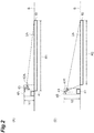
Figure 2] Figure 2(A) is a diagram showing an example of a camera sensor unit with a wide-angle lens, andFigure 2(B) is a diagram showing an example of a camera unit with a standard lens. - [
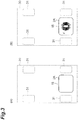
Figure 3] Figure 3(A) is a plan view showing a state in which no foreign object exists on the power transmission unit during power transmission by the power transmission device according to the first embodiment, andFigure 3(B) is a plan view showing a state in which a foreign object that generates heat exists on the power transmission unit during power transmission by the power transmission device according to the first embodiment. - [
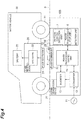
Figure 4] Figure 4 is a block diagram showing a foreign object detection device and a power transmission device according to a second embodiment. - [
Figure 5] Figure 5(A) is a plan view showing a state in which foreign object that generates heat exists on the power transmission unit during power transmission by the power transmission device according to a second embodiment, andFigure 5(B) is a plan view showing a state in which foreign object that does not generate heat exists on the power transmission unit during power transmission by the power transmission device according to the second embodiment. - A foreign object detection device according to one aspect of the present disclosure is a foreign object detection device detecting, during wireless power transfer from a power transmission unit of a power transmission device to a power reception unit of a power reception device, a foreign object on the power transmission unit, the foreign object detection device comprising: a temperature sensitive body disposed at the power transmission unit and changing a color with temperature; and a detection unit detecting the foreign object by detecting a change in the color.
- According to this foreign object detection device, provided is a foreign object detection device detecting, during wireless power transfer from a power transmission unit of a power transmission device to a power reception unit of a power reception device, a foreign object on the power transmission unit, and comprising: a temperature sensitive body that is disposed at the power transmission unit and changes a color with temperature; and a detection unit that detects the foreign object on the power transmission unit by detecting a change in the color of the temperature sensitive body. When the foreign object exists on the power transmission unit, the temperature around the foreign object rises and the color of the temperature sensitive body changes. The detection unit detects a change in the color of the temperature sensitive body, thereby detecting the foreign object on the power transmission unit. Thus, the foreign object on the power transmission unit can be detected with a simpler configuration.
- In some modes, on the temperature sensitive body, a pattern including a plurality of the colors may appear when the temperature changes, and the detection unit may detect the foreign object by detecting appearance of the pattern.
- With this configuration, a pattern containing a plurality of colors appears when the temperature changes on the temperature sensitive body, and the detection unit detects appearance of the pattern, thereby detecting the foreign object. Consequently, even if the color of the foreign object is the same as one of the colors included in the pattern on the temperature sensitive body, the foreign object that causes heat generation in the power transmission unit can be detected while preventing erroneous detection by detecting the other colors included in the pattern on the temperature sensitive body through the detection unit.
- In some modes, the pattern may be a checkered pattern.
- With this configuration in which the pattern is a checkered pattern, it is easier to detect the appearance of the pattern.
- In some modes, the temperature sensitive body may be disposed on the power transmission unit installed on a road surface, and the detection unit may comprise: a camera installed on the road surface and receiving light reflected off the temperature sensitive body; a lens collecting the light; and a mirror directing the light collected by the lens toward the camera.
- In this configuration, the temperature sensitive body is disposed on the power transmission unit installed on a road surface, and the detection unit comprises: a camera installed on the road surface and receiving light reflected off the temperature sensitive body; a lens collecting the light; and a mirror directing the light collected by the lens toward the camera. Hence, for example, when the power transmission unit installed on the road surface of such as a parking lot performs wireless power transfer to the power reception unit installed on the undersurface of the motor vehicle, the camera can be mounted on the road surface so that it can barely be a constraint on the facility. Also, by the lens and the mirror, it is possible to detect a wide area of the temperature sensitive body from a narrow gap between the road surface and the undersurface of the motor vehicle.
- The lens may be either a fisheye lens or a wide-angle lens.
- In this configuration, the lens is a wide-angle lens or a fisheye lens, so that the height of the detection unit with respect to the detection area can be lowered.
- A power transmission device according to another aspect of the present disclosure is a power transmission device comprising the foreign object detection device according to the one aspect of the present disclosure, and the power transmission unit.
- Embodiments of the present disclosure will now be described with reference to the accompanying drawings.
- As shown in
Figure 1 , apower transmission device 10A according to the first embodiment of the present disclosure comprises a foreignobject detection device 1A and apower transmission unit 15. Thepower transmission device 10A supplies power from thepower transmission unit 15 installed on a road surface S to apower reception unit 21 in apower reception device 20 mounted on amotor vehicle 30 by wireless power transfer. Thepower transmission device 10A is installed in, for example, a parking lot. Themotor vehicle 30 is, for example, an electric motor vehicle. Thepower transmission device 10A is configured to supply power to thepower reception device 20 mounted on themotor vehicle 30 such as an electric motor vehicle arriving at such as a parking lot by using magnetic coupling between coils using such as magnetic resonance or electromagnetic induction. Note that themotor vehicle 30 may be various mobile objects, such as plug-in hybrid motor vehicles and underwater vehicles, instead of electric motor vehicles. - As shown in
Figure 1 , thepower transmission device 10A comprises a foreignobject detection device 1A, aconverter 12, aninverter 13, a powertransmission control unit 14, and apower transmission unit 15. Thepower transmission device 10A is supplied with power from anexternal power source 11. Thepower source 11 supplies power required to generate the power to be transmitted to themotor vehicle 30, and supplies single-phase AC power like a commercial AC power source. Note that thepower source 11 is not limited to a single-phase AC power source, and may be a power source that supplies three-phase AC power. - The
converter 12 is an AC/DC converter that rectifies the AC power supplied from thepower source 11 and converts it into DC power. Theconverter 12 may have a power factor correction [PFC] function and a buck-boost function. It is also possible to use a DC power source such as a fuel cell or a solar battery as thepower source 11, and in that case, theconverter 12 can be omitted. When thepower source 11 is a DC power source, a DC/DC converter may be provided instead of theconverter 12. - The
inverter 13 converts the DC power from theconverter 12 into AC power (high frequency power) having a frequency higher than that of the AC power of thepower source 11 and supplies it to thepower transmission unit 15. The powertransmission control unit 14 is an electronic control unit including, for example, such as a central processing unit (CPU), a read only memory (ROM), and a random access memory (RAM). The powertransmission control unit 14 controls power supply from thepower transmission unit 15 of thepower transmission device 10A to thepower reception unit 21 of thepower reception device 20. The powertransmission control unit 14 controls the operations of theconverter 12 and theinverter 13 to change the magnitude of the power transmitted from thepower transmission unit 15 of thepower transmission device 10A to thepower reception unit 21 of thepower reception device 20. As will be described later, upon reception of a command signal that stops power transmission from the foreignobject detection device 1A that has detected foreign object, the powertransmission control unit 14 stops power transmission from thepower transmission unit 15 of thepower transmission device 10A to thepower reception unit 21 of thepower reception device 20. - The
power transmission unit 15 is a coil device installed on the road surface S of such as a parking lot. Thepower reception unit 21 of thepower reception device 20 is a coil device installed on the undersurface of themotor vehicle 30. An electromagnetic coupling circuit is formed by bringing thepower transmission unit 15 and thepower reception unit 21 close to each other. This electromagnetic coupling circuit refers to a circuit in which apower transmission unit 15 and apower reception unit 21 are electromagnetically coupled to transmit power from thepower transmission unit 15 to thepower reception unit 21 by wireless power transfer. Note that thepower transmission unit 15 and thepower reception unit 21 may perform wireless power transfer by electromagnetic induction or may perform wireless power transfer by magnetic resonance. Thepower transmission unit 15 and thepower reception unit 21 may be antenna devices. - The foreign
object detection device 1A detects foreign object F on thepower transmission unit 15 during wireless power transfer from thepower transmission unit 15 of thepower transmission device 10A to thepower reception unit 21 of thepower reception device 20. The foreign object F is a metal substance that causes heat generation between thepower transmission unit 15 and thepower reception unit 21. The foreign object F is, for example, such as an empty can. - The foreign
object detection device 1A comprises a temperaturesensitive body 2A and adetection unit 3A. The temperaturesensitive body 2A is disposed at thepower transmission unit 15, and its color changes with temperature. The temperaturesensitive body 2A is disposed on thepower transmission unit 15 installed on the road surface S. The temperaturesensitive body 2A is, for example, a temperature sensitive paint applied to the top surface of thepower transmission unit 15. The color of the temperaturesensitive body 2A changes when the temperature of thepower transmission unit 15 reaches a temperature of 40°C to 80°C at which power transmission to thepower reception device 20 through thepower transmission device 10A should be stopped. The temperaturesensitive body 2A is composed of, for example, a heavy metal iodide whose color changes reversibly with temperature. The temperaturesensitive body 2A is composed of, for example, Hg2[HgI4], Ag2[HgI4], and Cu2[HgI4]. - In this embodiment, the temperature
sensitive body 2A has, for example, an achromatic color such as white or black at a temperature of less than 40°C, and changes color to any one of the chromatic colors of red, blue, and green when the temperature reaches 40°C to 80°C. The temperaturesensitive body 2A in this embodiment is a kind of temperature sensitive paint applied to the entire top surface of thepower transmission unit 15. Note that the temperaturesensitive body 2A may have a chromatic color at a temperature of less than 40°C, and may change color to an achromatic color when the temperature reaches 40°C to 80°C. The temperaturesensitive body 2A may have the color of visible light when the temperature reaches 40°C to 80°C. - The
detection unit 3A detects the foreign object F on thepower transmission unit 15 by detecting a change in the color of the temperaturesensitive body 2A. Thedetection unit 3A has acamera sensor unit 4A, a colorchange detection unit 5, and a powertransmission stop unit 6. As shown inFigure 2(A) , thecamera sensor unit 4A of thedetection unit 3A is installed on the road surface S and has acamera 41 that receives the light reflected off the temperaturesensitive body 2A, alens 42A that collects the light reflected off the temperaturesensitive body 2A, and amirror 43 that directs the light collected by thelens 42A toward thecamera 41. - The
camera 41 is disposed on the top surface of thepower transmission unit 15 and receives the light reflected off the temperaturesensitive body 2A. Thecamera 41 is, for example, a charge coupled device (CCD) camera. Thecamera 41 only needs to be able to detect visible light. Thelens 42A is, for example, a wide-angle lens or a fisheye lens. Themirror 43 is disposed above thecamera 41 and directs the light collected by thelens 42A toward thecamera 41 disposed below themirror 43. - In this embodiment, since the
lens 42A is a wide-angle lens or a fisheye lens, the height h1 of thecamera sensor unit 4A with respect to the detection area R1 can be lowered. The detection area R1 lies over the entire top surface of thepower transmission unit 15. With the use of a wide-angle lens or a fisheye lens for thelens 42A, optical data can be acquired from a wide area. In the order arrangement in which the light collected by thelens 42A is reflected by themirror 43 and then sent to thecamera 41, acompact mirror 43 can be used and the device can be made compact. As shown inFigure 2(B) , when the detection area R2 need not be wide and the height h2 of thecamera sensor unit 4B need not be low because the top surface of thepower transmission unit 15 is small, a standard lens may be used as thelens 42B. - The color
change detection unit 5 shown inFigure 1 detects a change in the color of the temperaturesensitive body 2A by detecting the wavelength of the light received at thecamera 41 of thecamera sensor unit 4A. When the colorchange detection unit 5 detects a change in the color of the temperaturesensitive body 2A, the powertransmission stop unit 6 transmits a command signal for stopping the power transmission to the powertransmission control unit 14, thereby the power transmission to thepower reception device 20 through thepower transmission device 10A is stopped. - Meanwhile, the
power reception device 20 mounted on themotor vehicle 30 comprises apower reception unit 21 and arectifier 22. Thepower reception device 20 is a device that receives power from thepower transmission unit 15 of thepower transmission device 10A and supplies power to a load such as abattery 23 of themotor vehicle 30. As described above, thepower reception unit 21 is a coil device mounted between fourwheels 31 on the undersurface of themotor vehicle 30. The magnetic flux generated in thepower transmission unit 15 interlinks with thepower reception unit 21, so that thepower reception unit 21 generates induced current. Thus, thepower reception unit 21 wirelessly receives the power from thepower transmission unit 15. Therectifier 22 rectifies the AC power that thepower reception unit 21 has received from thepower transmission unit 15 and converts it into DC power. The DC power converted by therectifier 22 is supplied to a load such as thebattery 23 of themotor vehicle 30. - The operations of the foreign
object detection device 1A and thepower transmission device 10A of this embodiment will now be described. As shown inFigure 3(A) , during power transmission from thepower transmission unit 15 of thepower transmission device 10A to thepower reception unit 21 of thepower reception device 20 mounted on themotor vehicle 30, the color of the temperaturesensitive body 2A does not change if foreign object does not exist on the top surface of thepower transmission unit 15. The colorchange detection unit 5 of thedetection unit 3A does not detect a change in the color of the temperaturesensitive body 2A. Since the powertransmission stop unit 6 of thedetection unit 3A does not transmit a command signal for stopping power transmission to the powertransmission control unit 14, the powertransmission control unit 14 of thepower transmission device 10A continues power transmission. During power transmission from thepower transmission unit 15 of thepower transmission device 10A to thepower reception unit 21 of thepower reception device 20, the color of the temperaturesensitive body 2A does not change even if foreign object, such as a fallen leaf, that cannot be a cause of heat generation between thepower transmission unit 15 and thepower reception unit 21 exists on the top surface of thepower transmission unit 15, so that the powertransmission control unit 14 of thepower transmission device 10A continues power transmission. - As shown in
Figure 3(B) , during power transmission from thepower transmission unit 15 of thepower transmission device 10A to thepower reception unit 21 of thepower reception device 20, the color of the temperaturesensitive body 2A changes if foreign object F, such as an empty can, that causes heat generation between thepower transmission unit 15 and thepower reception unit 21 exists on the top surface of thepower transmission unit 15. The colorchange detection unit 5 of thedetection unit 3A detects a change in the color of the temperaturesensitive body 2A. The powertransmission stop unit 6 of thedetection unit 3A transmits a command signal for stopping power transmission to the powertransmission control unit 14, and the powertransmission control unit 14 of thepower transmission device 10A stops power transmission. - According to this embodiment, the foreign
object detection device 1A for detecting foreign object F on thepower transmission unit 15 during wireless power transfer from thepower transmission unit 15 of thepower transmission device 10A to thepower reception unit 21 of thepower reception device 20, comprises the temperaturesensitive body 2A that is disposed at thepower transmission unit 15 and changes color with temperature, and thedetection unit 3A that detects foreign object F on thepower transmission unit 15 by detecting a change in the color of the temperaturesensitive body 2A. When the foreign object F exists on thepower transmission unit 15, the temperature around the foreign object F rises and the color of the temperaturesensitive body 2A changes. Thedetection unit 3A detects a change in the color of the temperaturesensitive body 2A, thereby the foreign object F on thepower transmission unit 15 is detected. Thus, the foreign object F on thepower transmission unit 15 can be detected with a simpler configuration. - Further, according to this embodiment, for example, unlike in a method that detects foreign object F by measuring the magnetic field between the
power transmission unit 15 and thepower reception unit 21, foreign object F is detected by detecting a change in the color of the temperaturesensitive body 2A caused by heat generation. In other words, since the foreign object F is detected by directly detecting the heat generation, even if foreign object, such as a fallen leaf, that cannot be a cause of heat generation between thepower transmission unit 15 and thepower reception unit 21 exists on the top surface of thepower transmission unit 15, the foreign object F is not detected as a cause of heat generation. Hence, preventing erroneous detection prevents unnecessary interruption of power transmission by thepower transmission device 10A. Further, according to this embodiment, for example, unlike in a method that detects foreign object F by measuring the magnetic field between thepower transmission unit 15 and thepower reception unit 21, foreign object F is detected by directly detecting heat generation, which allows smaller foreign object F to be detected. Small foreign object F can be detected by adopting acamera 41 having sufficiently small pixels, that is, acamera 41 having a large number of pixels and high resolution so that the image of the foreign object F is projected onto one or more pixels of the imaging device when an image of foreign object F is formed on the imaging surface of thecamera 41 through the optical system (a combination of thelens 42A and themirror 43 or a combination of thelens 42B and the mirror 43). - Further, according to this embodiment, the temperature
sensitive body 2A is disposed on thepower transmission unit 15 installed on the road surface S, and thedetection unit 3A is installed on the road surface S and comprises acamera 41 that receives the light reflected off the temperaturesensitive body 2A, alens 42A that collects light, and amirror 43 that directs the light collected by thelens 42A toward thecamera 41. For this reason, for example, when thepower transmission unit 15 installed on the road surface S of such as a parking lot performs wireless power transfer to thepower reception unit 21 installed on the undersurface of themotor vehicle 30, thecamera 41 can be mounted on the road surface S so that it can barely be a constraint on the facility. By thelens 42A and themirror 43, it is possible to detect a wide area of the temperaturesensitive body 2A from a narrow gap between the road surface S and the undersurface of themotor vehicle 30. - The second embodiment of the present disclosure will now be described. As shown in
Figure 4 , the foreignobject detection device 1B and thepower transmission device 10B of this embodiment comprise a temperaturesensitive body 2B. The temperaturesensitive body 2B is, for example, a temperature sensitive paint applied to the top surface of thepower transmission unit 15. On the temperaturesensitive body 2B, a pattern including a plurality of colors appears when the temperature changes. A pattern containing a plurality of colors refers to, for example, the phenomenon in which a single achromatic color such as white or black appears at a temperature of less than 40°C, but a checkered pattern including any two or more chromatic colors of, for example, red, blue, and green appears when the temperature reaches 40°C to 80°C. - Note that the temperature
sensitive body 2B may have a single chromatic color at a temperature of less than 40°C, and a checkered pattern including two or more achromatic colors of, for example, white, black, and gray when the temperature reaches 40°C to 80°C. The pattern is not limited to a checkered pattern, and may be a combination of other figures, patterns, and colors. Also, on the temperaturesensitive body 2B, some pattern including a plurality of colors may appear at a temperature of less than 40°C, and some pattern including a plurality of colors may appear when the temperature reaches 40°C to 80°C. The pattern including a plurality of colors that appears when the temperature of the temperaturesensitive body 2B reaches 40°C to 80°C may be a pattern including the color of visible light. - The pattern
change detection unit 7 of thedetection unit 3B detects the foreign object F on thepower transmission unit 15 by detecting the pattern that appears on the temperaturesensitive body 2B. The patternchange detection unit 7 checks an image of the temperaturesensitive body 2B received by thecamera 41 of thecamera sensor unit 4A against the pattern including a plurality of colors that appears when the temperature of the temperaturesensitive body 2B reaches 40°C to 80°C and is stored in a storage device (not shown in the drawing) of the foreignobject detection device 1B. When the image of the temperaturesensitive body 2B and the stored pattern match, the patternchange detection unit 7 detects the presence of the foreign object F on thepower transmission unit 15. When the patternchange detection unit 7 detects a pattern including a plurality of colors on the temperaturesensitive body 2B, the powertransmission stop unit 6 transmits a command signal for stopping the power transmission to the powertransmission control unit 14, thereby the power transmission to thepower reception device 20 through thepower transmission device 10B is stopped. - The operations of the foreign
object detection device 1B and thepower transmission device 10B of this embodiment will now be described. As shown inFigure 5(A) , during power transmission from thepower transmission unit 15 of thepower transmission device 10B to thepower reception unit 21 of thepower reception device 20, apattern 2p including a plurality of colors appears on the temperaturesensitive body 2B if foreign object F, such as an empty can, that causes heat generation between thepower transmission unit 15 and thepower reception unit 21 exists on the top surface of thepower transmission unit 15. The patternchange detection unit 7 of thedetection unit 3B detects thepattern 2p appearing on the temperaturesensitive body 2B. The powertransmission stop unit 6 of thedetection unit 3B transmits a command signal for stopping power transmission to the powertransmission control unit 14, and the powertransmission control unit 14 of thepower transmission device 10B stops power transmission. - A description will now be given of the case where as shown in
Figure 5(B) , during power transmission from thepower transmission unit 15 of thepower transmission device 10B to thepower reception unit 21 of thepower reception device 20, foreign object f, such as a fallen leaf, that cannot be a cause of heat generation between thepower transmission unit 15 and thepower reception unit 21 exists on the top surface of thepower transmission unit 15. Even when the color of the foreign object f is the same as one of the colors included in thepattern 2p on the temperaturesensitive body 2B, thepattern 2p on the temperaturesensitive body 2B does not appear. Consequently, the patternchange detection unit 7 of thedetection unit 3B does not detect thepattern 2p appearing on the temperaturesensitive body 2B. The powertransmission control unit 14 of thepower transmission device 10A continues power transmission. - According to this embodiment, a
pattern 2p containing a plurality of colors appears when the temperature changes on the temperaturesensitive body 2B, and thedetection unit 3B detects thepattern 2p that appears on the temperaturesensitive body 2B, thereby the foreign object F on thepower transmission unit 15 is detected. Consequently, even if the colors of the foreign objects F and f are the same as one of the colors included in thepattern 2p on the temperaturesensitive body 2B, the foreign object F that causes heat generation in thepower transmission unit 15 can be detected while preventing erroneous detection by detecting the other colors included in thepattern 2p on the temperaturesensitive body 2B through thedetection unit 3B. Preventing erroneous detection prevents unnecessary interruption of power transmission by thepower transmission device 10B. - Although the embodiments and modifications of the present disclosure have been described so far, the present disclosure is not limited to the above-described embodiments. For instance, the temperature
sensitive bodies power transmission unit 15 and changes color with temperature. Also, when the foreignobject detection devices power transmission devices object detection devices power transmission devices power transmission devices cameras 41 of thecamera sensor units power transmission unit 15 and thepower reception unit 21 can be photographed. - In the foreign object detection device and the power transmission device of the present disclosure, a foreign object on the power transmission unit can be detected with a simpler configuration.
-
- 1A, 1B Foreign object detection device
- 2A, 2B Temperature sensitive body
- 2p Pattern
- 3A, 3B Detection unit
- 4A, 4B Camera sensor unit
- 5 Color change detection unit
- 6 Power transmission stop unit
- 7 Pattern change detection unit
- 10A, 10B Power transmission device
- 11 Power source
- 12 Converter
- 13 Inverter
- 14 Power transmission control unit
- 15 Power transmission unit
- 20 Power reception device
- 21 Power reception unit
- 22 Rectifier
- 23 Battery
- 30 Motor vehicle
- 31 Wheel
- 41 Camera
- 42A, 42B Lens
- 43 Mirror
- S Road surface
- h1, h2 Height
- R1, R2 Detection area
- F, f Foreign object
Claims (6)
- A foreign object detection device detecting, during wireless power transfer from a power transmission unit of a power transmission device to a power reception unit of a power reception device, a foreign object on the power transmission unit, the foreign object detection device comprising:a temperature sensitive body disposed at the power transmission unit and changing a color with temperature; anda detection unit detecting the foreign object by detecting a change in the color.
- The foreign object detection device according to Claim 1, wherein
on the temperature sensitive body, a pattern including a plurality of the colors appears when temperature changes, and
the detection unit detects the foreign object by detecting appearance of the pattern. - The foreign object detection device according to Claim 2, wherein the pattern is a checkered pattern.
- The foreign object detection device according to any one of Claims 1 to 3, wherein
the temperature sensitive body is disposed on the power transmission unit installed on a road surface, and
the detection unit comprises:a camera installed on the road surface and receiving light reflected off the temperature sensitive body;a lens collecting the light; anda mirror directing the light collected by the lens toward the camera. - The foreign object detection device according to Claim 4, wherein the lens is either a fisheye lens or wide-angle lens.
- A power transmission device comprising the foreign object detection device according to any one of Claims 1 to 5, and the power transmission unit.
Applications Claiming Priority (2)
| Application Number | Priority Date | Filing Date | Title |
|---|---|---|---|
| JP2018173459 | 2018-09-18 | ||
| PCT/JP2019/032290 WO2020059379A1 (en) | 2018-09-18 | 2019-08-19 | Foreign matter detection device and power transmission device |
Publications (2)
| Publication Number | Publication Date |
|---|---|
| EP3855600A1 true EP3855600A1 (en) | 2021-07-28 |
| EP3855600A4 EP3855600A4 (en) | 2022-06-15 |
Family
ID=69887055
Family Applications (1)
| Application Number | Title | Priority Date | Filing Date |
|---|---|---|---|
| EP19863566.6A Pending EP3855600A4 (en) | 2018-09-18 | 2019-08-19 | FOREIGN MATTER DETECTION DEVICE AND POWER TRANSMISSION DEVICE |
Country Status (4)
| Country | Link |
|---|---|
| US (1) | US11731521B2 (en) |
| EP (1) | EP3855600A4 (en) |
| JP (1) | JP7020563B2 (en) |
| WO (1) | WO2020059379A1 (en) |
Cited By (3)
| Publication number | Priority date | Publication date | Assignee | Title |
|---|---|---|---|---|
| WO2023150546A1 (en) * | 2022-02-03 | 2023-08-10 | Witricity Corporation | Foreign object detection using hybrid inductive and capacitive sensing |
| WO2023150484A1 (en) * | 2022-02-03 | 2023-08-10 | Witricity Corporation | Foreign object detection using combined inductive and thermal sensing |
| US11945319B2 (en) | 2017-01-10 | 2024-04-02 | Witricity Corporation | Foreign object detection using heat sensitive material and inductive sensing |
Families Citing this family (1)
| Publication number | Priority date | Publication date | Assignee | Title |
|---|---|---|---|---|
| US11923697B2 (en) | 2020-11-04 | 2024-03-05 | Samsung Electronics Co., Ltd. | Wireless power transmitting apparatus and method for controlling wireless power transmitting apparatus |
Family Cites Families (11)
| Publication number | Priority date | Publication date | Assignee | Title |
|---|---|---|---|---|
| JPH062975U (en) | 1992-06-05 | 1994-01-14 | 株式会社高岳製作所 | Electric motor |
| JP3361682B2 (en) | 1995-02-07 | 2003-01-07 | 茂樹 小林 | Imaging target region positioning imaging device, inspection device, shape measurement device, and product manufacturing method |
| JP4911928B2 (en) | 2005-07-14 | 2012-04-04 | 中国電力株式会社 | Monitoring system |
| US20120112691A1 (en) * | 2008-09-27 | 2012-05-10 | Kurs Andre B | Wireless energy transfer for vehicles |
| US20110074346A1 (en) * | 2009-09-25 | 2011-03-31 | Hall Katherine L | Vehicle charger safety system and method |
| JP5691863B2 (en) | 2011-06-09 | 2015-04-01 | トヨタ自動車株式会社 | Power receiving device, vehicle, power transmitting device, and non-contact power feeding system |
| US8659408B2 (en) * | 2012-05-22 | 2014-02-25 | Delphi Technologies, Inc. | Object detection system and method using a camera and a multiple zone temperature sensor |
| US9893549B2 (en) * | 2012-10-25 | 2018-02-13 | Nokia Technologies Oy | Foreign object detection |
| US9304042B2 (en) * | 2013-01-18 | 2016-04-05 | Delphi Technologies, Inc. | Foreign object detection system and method suitable for source resonator of wireless energy transfer system |
| EP3855599B1 (en) * | 2015-12-24 | 2024-09-25 | Energous Corporation | Systems and methods of object detection in wireless power charging systems |
| US10128697B1 (en) * | 2017-05-01 | 2018-11-13 | Hevo, Inc. | Detecting and deterring foreign objects and living objects at wireless charging stations |
-
2019
- 2019-08-19 EP EP19863566.6A patent/EP3855600A4/en active Pending
- 2019-08-19 JP JP2020548146A patent/JP7020563B2/en active Active
- 2019-08-19 US US17/265,243 patent/US11731521B2/en active Active
- 2019-08-19 WO PCT/JP2019/032290 patent/WO2020059379A1/en not_active Ceased
Cited By (5)
| Publication number | Priority date | Publication date | Assignee | Title |
|---|---|---|---|---|
| US11945319B2 (en) | 2017-01-10 | 2024-04-02 | Witricity Corporation | Foreign object detection using heat sensitive material and inductive sensing |
| WO2023150546A1 (en) * | 2022-02-03 | 2023-08-10 | Witricity Corporation | Foreign object detection using hybrid inductive and capacitive sensing |
| WO2023150484A1 (en) * | 2022-02-03 | 2023-08-10 | Witricity Corporation | Foreign object detection using combined inductive and thermal sensing |
| US12184087B2 (en) | 2022-02-03 | 2024-12-31 | Witricity Corporation | Foreign object detection using combined inductive and thermal sensing |
| US12609559B2 (en) | 2022-02-03 | 2026-04-21 | WiTricity AI Tech, LLC | Foreign object detection using hybrid inductive and capacitive sensing |
Also Published As
| Publication number | Publication date |
|---|---|
| US20220396158A1 (en) | 2022-12-15 |
| JPWO2020059379A1 (en) | 2021-08-30 |
| US11731521B2 (en) | 2023-08-22 |
| JP7020563B2 (en) | 2022-02-16 |
| EP3855600A4 (en) | 2022-06-15 |
| WO2020059379A1 (en) | 2020-03-26 |
Similar Documents
| Publication | Publication Date | Title |
|---|---|---|
| US11731521B2 (en) | Foreign matter detection device and power transmission device | |
| US20250187460A1 (en) | Method for controlling power transmitting device, method for detecting foreign object, and power transmitting device in wireless power transmission system | |
| US11904712B2 (en) | Foreign object detection for wireless power transfer systems | |
| US10581283B2 (en) | Method for controlling power transmitting device, method for detecting foreign object, and power transmitting device in wireless power transmission system | |
| JP5440621B2 (en) | Non-contact power feeding device | |
| US11220191B2 (en) | Vehicle charging system, vehicle, and authentication method for vehicle charging system | |
| JP2010226945A (en) | Mobile power supply system | |
| RU2594175C1 (en) | Contactless electric power supply system | |
| EP2803522A1 (en) | Foreign object detection device and non-contact power transfer device | |
| US20110187320A1 (en) | Wireless charging apparatus and wireless charging system | |
| US20220085662A1 (en) | Wireless power transmission using multiple transmitters and receivers | |
| CN105515224A (en) | Mobile charging device for charging electric car and charging system with mobile charging device | |
| JP2017528097A (en) | Method and system for object detection and sensing for a wireless charging system | |
| US20160341821A1 (en) | Methods and apparatus utilizing digital signal processing of ultra wide band radar signals for living object detection in wireless power transfer applications | |
| WO2015012589A1 (en) | Apparatus for transmitting wireless power for electric car | |
| US10886788B2 (en) | Power transfer device and power transfer system | |
| CN103368275B (en) | Electric power supply device, power receiving apparatus, method of state management and program | |
| US7262800B2 (en) | Optical sensor unit provided with radio optical sensor having radio element and radio communication means apart from the radio optical sensor, optical sensor array and method of driving optical sensor | |
| US20230202324A1 (en) | Macroscopic alignment method for wireless charging of electric vehicle and apparatus and system therefor | |
| JP2005294920A (en) | Imaging apparatus and imaging system using the imaging apparatus | |
| JP2018133931A (en) | vehicle | |
| JP2023044864A (en) | Foreign matter detection device, wireless power transmission device, wireless power reception device and wireless power transmission system | |
| CN111586225B (en) | Image acquisition auxiliary system | |
| KR102690491B1 (en) | Apartment parking convenience system for supporting electric vehicle charging quickly | |
| KR20250084018A (en) | Ground assembly for wireless charging of electric vehicle and method for controlling wireless charging thereof |
Legal Events
| Date | Code | Title | Description |
|---|---|---|---|
| STAA | Information on the status of an ep patent application or granted ep patent |
Free format text: STATUS: THE INTERNATIONAL PUBLICATION HAS BEEN MADE |
|
| PUAI | Public reference made under article 153(3) epc to a published international application that has entered the european phase |
Free format text: ORIGINAL CODE: 0009012 |
|
| STAA | Information on the status of an ep patent application or granted ep patent |
Free format text: STATUS: REQUEST FOR EXAMINATION WAS MADE |
|
| 17P | Request for examination filed |
Effective date: 20210331 |
|
| AK | Designated contracting states |
Kind code of ref document: A1 Designated state(s): AL AT BE BG CH CY CZ DE DK EE ES FI FR GB GR HR HU IE IS IT LI LT LU LV MC MK MT NL NO PL PT RO RS SE SI SK SM TR |
|
| DAV | Request for validation of the european patent (deleted) | ||
| DAX | Request for extension of the european patent (deleted) | ||
| A4 | Supplementary search report drawn up and despatched |
Effective date: 20220513 |
|
| RIC1 | Information provided on ipc code assigned before grant |
Ipc: H02J 50/10 20160101ALN20220509BHEP Ipc: B60L 53/124 20190101ALI20220509BHEP Ipc: H02J 50/60 20160101AFI20220509BHEP |