EP3855551A1 - Battery cell thermal conductivity measurement device and battery cell thermal conductivity measurement method using same - Google Patents
Battery cell thermal conductivity measurement device and battery cell thermal conductivity measurement method using same Download PDFInfo
- Publication number
- EP3855551A1 EP3855551A1 EP20825793.1A EP20825793A EP3855551A1 EP 3855551 A1 EP3855551 A1 EP 3855551A1 EP 20825793 A EP20825793 A EP 20825793A EP 3855551 A1 EP3855551 A1 EP 3855551A1
- Authority
- EP
- European Patent Office
- Prior art keywords
- hot plate
- battery cell
- plate
- denotes
- measuring
- Prior art date
- Legal status (The legal status is an assumption and is not a legal conclusion. Google has not performed a legal analysis and makes no representation as to the accuracy of the status listed.)
- Granted
Links
Images




Classifications
-
- H—ELECTRICITY
- H01—ELECTRIC ELEMENTS
- H01M—PROCESSES OR MEANS, e.g. BATTERIES, FOR THE DIRECT CONVERSION OF CHEMICAL ENERGY INTO ELECTRICAL ENERGY
- H01M10/00—Secondary cells; Manufacture thereof
- H01M10/42—Methods or arrangements for servicing or maintenance of secondary cells or secondary half-cells
- H01M10/4285—Testing apparatus
-
- G—PHYSICS
- G01—MEASURING; TESTING
- G01N—INVESTIGATING OR ANALYSING MATERIALS BY DETERMINING THEIR CHEMICAL OR PHYSICAL PROPERTIES
- G01N25/00—Investigating or analyzing materials by the use of thermal means
- G01N25/18—Investigating or analyzing materials by the use of thermal means by investigating thermal conductivity
-
- G—PHYSICS
- G01—MEASURING; TESTING
- G01N—INVESTIGATING OR ANALYSING MATERIALS BY DETERMINING THEIR CHEMICAL OR PHYSICAL PROPERTIES
- G01N25/00—Investigating or analyzing materials by the use of thermal means
- G01N25/20—Investigating or analyzing materials by the use of thermal means by investigating the development of heat, i.e. calorimetry, e.g. by measuring specific heat, by measuring thermal conductivity
-
- G—PHYSICS
- G01—MEASURING; TESTING
- G01N—INVESTIGATING OR ANALYSING MATERIALS BY DETERMINING THEIR CHEMICAL OR PHYSICAL PROPERTIES
- G01N25/00—Investigating or analyzing materials by the use of thermal means
- G01N25/20—Investigating or analyzing materials by the use of thermal means by investigating the development of heat, i.e. calorimetry, e.g. by measuring specific heat, by measuring thermal conductivity
- G01N25/48—Investigating or analyzing materials by the use of thermal means by investigating the development of heat, i.e. calorimetry, e.g. by measuring specific heat, by measuring thermal conductivity on solution, sorption, or a chemical reaction not involving combustion or catalytic oxidation
- G01N25/4806—Details not adapted to a particular type of sample
- G01N25/4826—Details not adapted to a particular type of sample concerning the heating or cooling arrangements
-
- G—PHYSICS
- G01—MEASURING; TESTING
- G01R—MEASURING ELECTRIC VARIABLES; MEASURING MAGNETIC VARIABLES
- G01R31/00—Arrangements for testing electric properties; Arrangements for locating electric faults; Arrangements for electrical testing characterised by what is being tested not provided for elsewhere
- G01R31/36—Arrangements for testing, measuring or monitoring the electrical condition of accumulators or electric batteries, e.g. capacity or state of charge [SoC]
-
- H—ELECTRICITY
- H01—ELECTRIC ELEMENTS
- H01M—PROCESSES OR MEANS, e.g. BATTERIES, FOR THE DIRECT CONVERSION OF CHEMICAL ENERGY INTO ELECTRICAL ENERGY
- H01M10/00—Secondary cells; Manufacture thereof
- H01M10/42—Methods or arrangements for servicing or maintenance of secondary cells or secondary half-cells
- H01M10/425—Structural combination with electronic components, e.g. electronic circuits integrated to the outside of the casing
-
- H—ELECTRICITY
- H01—ELECTRIC ELEMENTS
- H01M—PROCESSES OR MEANS, e.g. BATTERIES, FOR THE DIRECT CONVERSION OF CHEMICAL ENERGY INTO ELECTRICAL ENERGY
- H01M10/00—Secondary cells; Manufacture thereof
- H01M10/42—Methods or arrangements for servicing or maintenance of secondary cells or secondary half-cells
- H01M10/48—Accumulators combined with arrangements for measuring, testing or indicating the condition of cells, e.g. the level or density of the electrolyte
-
- H—ELECTRICITY
- H01—ELECTRIC ELEMENTS
- H01M—PROCESSES OR MEANS, e.g. BATTERIES, FOR THE DIRECT CONVERSION OF CHEMICAL ENERGY INTO ELECTRICAL ENERGY
- H01M10/00—Secondary cells; Manufacture thereof
- H01M10/42—Methods or arrangements for servicing or maintenance of secondary cells or secondary half-cells
- H01M10/48—Accumulators combined with arrangements for measuring, testing or indicating the condition of cells, e.g. the level or density of the electrolyte
- H01M10/486—Accumulators combined with arrangements for measuring, testing or indicating the condition of cells, e.g. the level or density of the electrolyte for measuring temperature
-
- H—ELECTRICITY
- H01—ELECTRIC ELEMENTS
- H01M—PROCESSES OR MEANS, e.g. BATTERIES, FOR THE DIRECT CONVERSION OF CHEMICAL ENERGY INTO ELECTRICAL ENERGY
- H01M10/00—Secondary cells; Manufacture thereof
- H01M10/60—Heating or cooling; Temperature control
- H01M10/65—Means for temperature control structurally associated with the cells
- H01M10/655—Solid structures for heat exchange or heat conduction
- H01M10/6551—Surfaces specially adapted for heat dissipation or radiation, e.g. fins or coatings
-
- H—ELECTRICITY
- H01—ELECTRIC ELEMENTS
- H01M—PROCESSES OR MEANS, e.g. BATTERIES, FOR THE DIRECT CONVERSION OF CHEMICAL ENERGY INTO ELECTRICAL ENERGY
- H01M50/00—Constructional details or processes of manufacture of the non-active parts of electrochemical cells other than fuel cells, e.g. hybrid cells
- H01M50/10—Primary casings; Jackets or wrappings
- H01M50/102—Primary casings; Jackets or wrappings characterised by their shape or physical structure
- H01M50/105—Pouches or flexible bags
-
- H—ELECTRICITY
- H01—ELECTRIC ELEMENTS
- H01M—PROCESSES OR MEANS, e.g. BATTERIES, FOR THE DIRECT CONVERSION OF CHEMICAL ENERGY INTO ELECTRICAL ENERGY
- H01M50/00—Constructional details or processes of manufacture of the non-active parts of electrochemical cells other than fuel cells, e.g. hybrid cells
- H01M50/10—Primary casings; Jackets or wrappings
- H01M50/116—Primary casings; Jackets or wrappings characterised by the material
-
- H—ELECTRICITY
- H01—ELECTRIC ELEMENTS
- H01M—PROCESSES OR MEANS, e.g. BATTERIES, FOR THE DIRECT CONVERSION OF CHEMICAL ENERGY INTO ELECTRICAL ENERGY
- H01M10/00—Secondary cells; Manufacture thereof
- H01M10/42—Methods or arrangements for servicing or maintenance of secondary cells or secondary half-cells
- H01M10/425—Structural combination with electronic components, e.g. electronic circuits integrated to the outside of the casing
- H01M2010/4271—Battery management systems including electronic circuits, e.g. control of current or voltage to keep battery in healthy state, cell balancing
-
- Y—GENERAL TAGGING OF NEW TECHNOLOGICAL DEVELOPMENTS; GENERAL TAGGING OF CROSS-SECTIONAL TECHNOLOGIES SPANNING OVER SEVERAL SECTIONS OF THE IPC; TECHNICAL SUBJECTS COVERED BY FORMER USPC CROSS-REFERENCE ART COLLECTIONS [XRACs] AND DIGESTS
- Y02—TECHNOLOGIES OR APPLICATIONS FOR MITIGATION OR ADAPTATION AGAINST CLIMATE CHANGE
- Y02E—REDUCTION OF GREENHOUSE GAS [GHG] EMISSIONS, RELATED TO ENERGY GENERATION, TRANSMISSION OR DISTRIBUTION
- Y02E60/00—Enabling technologies; Technologies with a potential or indirect contribution to GHG emissions mitigation
- Y02E60/10—Energy storage using batteries
Definitions
- the present invention relates to an apparatus for measuring a thermal property of a pouch type battery cell, and specifically the thermal conductivity of a battery cell, and a method for measuring the thermal conductivity using the same.
- lithium secondary batteries such as lithium ion batteries and lithium ion polymer batteries having high energy density, discharge voltage, and output stability.
- a pouch type battery having a stack type or stack/folding type electrode assembly embedded in a pouch-shaped battery case of an aluminum laminate sheet has attracted a lot of attention due to its low manufacturing cost and small weight, and the amount used thereof is gradually increasing.
- the pouch-type battery cell accommodates a stacked or stack-folding electrode assembly manufactured by stacking a positive electrode, a separator, and a negative electrode. Each positive electrode and negative electrode are electrically connected by electrode tabs, and electrode leads that are drawn out are connected to the electrode tabs.
- the electrode assembly to which the electrode tab and the electrode lead are connected is stored in a pouch-shaped battery case, and then electrolyte is injected.
- a pouch type battery cell is manufactured by sealing a battery case while a part of the electrode lead is exposed to the outside.
- the battery case of the pouch-type battery cell is made of a pouch shape and is easy to process, so there are few restrictions according to the size or shape of the electrode assembly, and the space inside the battery cell can be efficiently used. Therefore, the pouch-type battery cell has a high energy density and can be processed in various forms, and has recently been used in mobile devices and automobile batteries in various forms.
- the pouch-type battery cell is applied with a high energy density ranging from a small device to a large device, a temperature rise may occur inside the device. Since this temperature rise affects the performance of the device itself or causes a risk of fire, explosion, etc., it is important to grasp the flow of heat discharged from the battery cell, that is, the thermal conductivity of the battery cell.
- the thermal conductivity refers to a value indicating the degree of heat conduction in an object, and is a value obtained by dividing the amount of heat flowing in a unit time past a unit area perpendicular to the flow of heat by a difference in temperature per unit length. Therefore, it means that the higher the thermal conductivity, the better the heat is passed, and in general, metals have high thermal conductivity.
- the guarded hot plate method is a method for measuring the thermal conductivity of a solid sample (specimen) and is performed according to a principle of measuring the thermal conductivity by measuring the amount of heat flowing from the high temperature side to the low temperature side while accurately measuring the temperature on both sides of the sample. That is, an auxiliary hot plate called a guarded hot plate is disposed around a hot plate so that heat flow can be accurately formed in one dimension in the sample, so that the hot plate has a constant temperature. In addition, the heat should be moved in the direction perpendicular to the surface of the plate to calculate the correct thermal conductivity.
- the hot plate and the guarded hot plate are disposed in a state that is spaced apart by a certain distance, and sometimes the space between them is filled with a material having low thermal conductivity.
- the conventional guarded hot plate method is designed only for the measurement of a simple type of test piece made of a single material.
- the two-piece method also differs in that it measures the heat flow in the upward and downward directions using two test pieces, but it is the same as the conventional method, except that the accuracy is increased by averaging the thermal conductivities in the upward and downward directions, and is basically not different from the conventional method in that it targets a single material having one-sided thermal conductivity.
- a pouch type battery cell unlike the test piece of a single material, it contains various materials with different properties such as positive electrode and negative electrode current collectors, separators, electrode mixtures, and battery cases, and the arrangement of each material is not evenly distributed. Hence, it is different from single material specimen.
- An object of the present invention is to provide an apparatus for independently measuring the thermal conductivity of a battery cell that exhibits anisotropy in each direction and a measuring method using the same, by improving a conventional thermal conductivity measuring apparatus and measuring method in which it is difficult to measure the thermal characteristics of the battery cell.
- an apparatus for measuring thermal conductivity of a battery cell may include: a hot plate including a heating element; and a guarded hot plate surrounding the hot plate, which is spaced from a side of the hot plate.
- a measuring plate, a cooling plate, and a cooling unit may be sequentially provided at upper and lower parts respectively in a direction perpendicular to the hot plate and in a direction away from the hoy plate,
- the measuring plate, the cooling plate, and the cooling unit respectively disposed in the upper and lower directions of the hot plate have a symmetrical structure about the hot plate, and one battery cell may be disposed between the upper and lower measuring plates and the cooling plate to measure thermal conductivity.
- the guarded hot plate is for inducing the heat transfer direction of the hot plate linearly in the vertical direction on the basis of the hot plate in one dimension and is characterized in that it is maintained at a temperature equal to or higher than that of the hot plate so that the heat generated from the hot plate is not moved to the side.
- the thickness of the measuring plate is characterized in that it increases in proportion to the amount of heat generated in the hot plate.
- the measuring plate may have a heat tendency to a high temperature surface closer to the hot plate and a low temperature surface closer to the cooling plate. As the distance between the high temperature surface and the low temperature surface increases, heat flow tends to be uniform. However, since the heat loss increases as the thickness increases, it is necessary to adjust the thickness to an appropriate thickness according to the amount of heat.
- the measuring plate is made of a metal material having excellent thermal conductivity and a well-known reference value.
- the measuring plate is preferably a metal or metal alloy having a thermal conductivity of 50 W/m ⁇ K or more, and more specifically, is characterized by comprising a metal material that is aluminum, copper, or an alloy thereof.
- a guarded measuring plate surrounding the measuring plate at a position spaced apart from the measuring plate on the side of the measuring plate may be further included, in which case heat loss in the measuring plate can be further reduced.
- a heat insulating member comprising a heat insulating material may be provided covering the side surfaces of the guarded hot plate, the measuring plates, the cooling plates, the cooling units, and the battery cells, in a spaced state so that direct heat transfer is not achieved through the insulating member so that direct heat transfer is not achieved through the heat insulating member.
- the hot plate may be in the form of a cylinder or a cuboid.
- the shape of the hot plate is not limited, but in order to suppress heat loss in the lateral direction and promote one-dimensional heat transfer in the vertical direction, it may be rectangular or square, most preferably circular.
- the battery cell thermal conductivity measuring apparatus of the present invention it is possible to separately measure the thermal conductivity of the battery cells, each of which exhibits different thermal characteristics in the upward and downward directions of the battery cell. Specifically, through the following steps, it is possible to separately measure upward and downward directions in the vertical direction. a step of calculating an amount of heat applied to the battery cell in an upward direction perpendicular to a hot plate; a step of calculating an amount of heat applied to the battery cell in a downward direction perpendicular to the hot plate; and a step of calculating a thermal conductivity of the battery cell by using the amount of heat applied in the upward direction and the amount of heat applied in the downward direction.
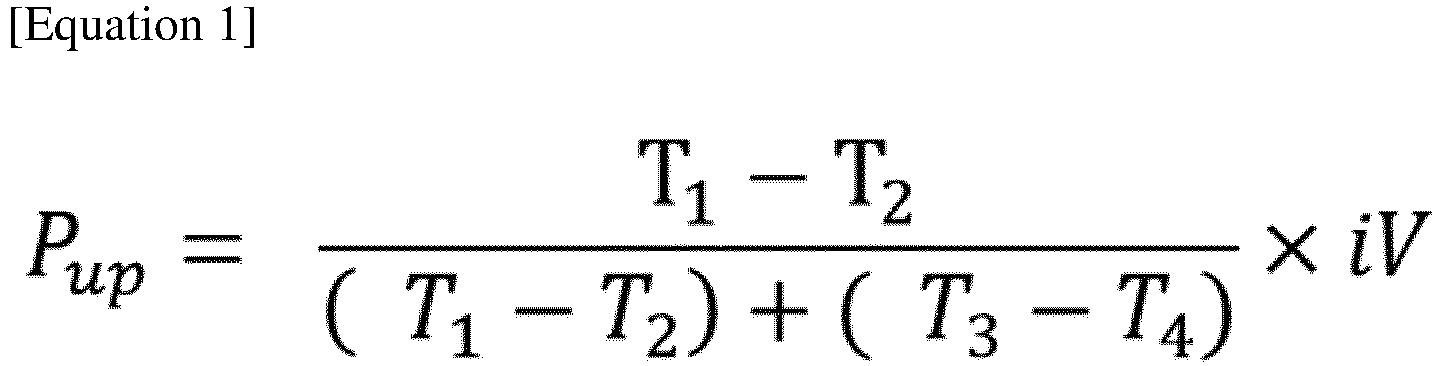
- Equation 1 the amount of heat applied to the battery cell in the upward direction perpendicular to the hot plate may be calculated by Equation 1 below.
- P up T 1 ⁇ T 2 T 1 ⁇ T 2 + T 3 ⁇ T 4 ⁇ iV
- P up denotes an amount of heat applied to a battery cell in an upward energy integration. If heat is not efficiently discharged when high heat is generated in the secondary battery, a thermal runaway phenomenon may occur in the secondary battery itself, and it may have a bad influence depending on the thermal characteristics of the electronic device including the secondary battery. Therefore, it is very important to measure the thermal characteristics of the pouch-type battery cell.
- the thermal conductivity measuring apparatus of the present invention is characterized in that it is possible to separately measure a vertical thermal conductivity from the lower surface to the upper surface of the battery cell and a vertical thermal conductivity from the upper surface to the lower surface of the battery cell.
- the apparatus for measuring thermal conductivity of the present invention includes a hot plate including a heating element; and a guarded hot plate surrounding the hot plate in a state spaced from the side of the hot plate.
- a measuring plate, a cooling plate, and a cooling unit may be sequentially provided at upper and lower parts in a direction perpendicular to the hot plate, and the measuring plate, the cooling plate, and the cooling unit respectively disposed in the upper and lower directions of the hot plate have a symmetrical structure about the hot plate. Due to this structure, heat generated in the hot plate moves vertically from the hot plate to the cooling plate in the vertical direction.
- one battery cell may be disposed between the upper and lower measuring plates and the cooling plate to measure thermal conductivity.
- the guarded hot plate is for inducing the heat transfer direction of the hot plate linearly in the vertical direction on the basis of the hot plate in one dimension and is characterized in that it is maintained at a temperature equal to or higher than that of the hot plate so that the heat generated from the hot plate is not moved to the side. If the guarded hot plate is dropped to a lower temperature than the hot plate, it is difficult to accurately measure the thermal conductivity since heat transfer also occurs to the side due to the characteristic of moving from a high temperature to a low temperature.
- the thickness of the measuring plate is characterized in that it increases in proportion to the amount of heat generated in the hot plate.
- the measuring plate may have a heat tendency to a high temperature surface closer to the hot plate and a low temperature surface closer to the cooling plate. As the distance between the high temperature surface and the low temperature surface increases, heat flow tends to be uniform. That is, the thicker the thickness of the measuring plate, the more precisely the thermal characteristics can be measured. However, since the heat loss increases as the thickness increases, it is necessary to adjust the thickness to an appropriate thickness according to the amount of heat generated from the hot plate.
- the measuring plate comprises a metal material having excellent thermal conductivity and a well-known reference value. Specifically, as the material of the measuring plate, aluminum, copper, or alloys thereof may be selected and used. If the thermal conductivity is low, the heat loss increases as much, making it difficult to accurately measure the amount of heat.
- the measuring plate is a component that is a standard for measuring thermal conductivity, and when calculating thermal conductivity, the temperatures of one surface close to the hot plate and the other surface close to the cooling plate are measured.
- the measuring plate may be designed with a structure similar to that of the hot plate.
- a guarded measuring plate surrounding the measuring plate at a position spaced apart from the measuring plate on the side of the measuring plate may be further included, in which case heat loss in the measuring plate can be further reduced.
- a heat insulating member comprising a heat insulating material may be provided covering the side surfaces of the guarded hot plate, the measuring plates, the cooling plates, the cooling units, and the battery cells, in a spaced state so that direct heat transfer is not achieved through the insulating member.
- a heat insulating member comprising a heat insulating material may be provided covering the side surfaces of the guarded hot plate, the guarded measuring plates, the cooling plates, the cooling units, and the battery cells, in a spaced state so that direct heat transfer is not achieved through the insulating member.
- the hot plate may be in the form of a cylinder or a cuboid.
- the shape of the hot plate is not limited, but in order to suppress heat loss in the lateral direction and promote one-dimensional heat transfer in the vertical direction, it may be rectangular or square, most preferably circular.
- the battery cell thermal conductivity measuring apparatus of the present invention it is possible to separately measure the thermal conductivity of the battery cells, each of which exhibits different thermal characteristics in the upward and downward directions of the battery cell. Specifically, through the following steps, it is possible to separately measure upward and downward directions in the vertical direction. a step of calculating an amount of heat applied to the battery cell in an upward direction perpendicular to the hot plate; a step of calculating an amount of heat applied to the battery cell in a downward direction perpendicular to the hot plate; a step of calculating a thermal conductivity of the battery cell by using the amount of heat applied in the upward direction and the amount of heat applied in the downward direction.
- a two-piece method is performed based on a principle that forms a constant heat flux in the vertical direction of the main hot plate while the temperatures of the main hot plate and the auxiliary hot plate are set to be the same. Accordingly, the size of the auxiliary hot plate should be very large, and the auxiliary hot plate should be maintained at the same temperature as that of the hot plate. Also, assuming that the upper and lower test pieces have the same material and material conductivity, the calorific value is obtained as the average of the conductivity in the upward and downward directions. Therefore, it is suitable for measuring the thermal properties of an isotropic material or a heat insulating material having a uniform thermal conductivity, but the thermal conductivity of a pouch-type battery cell cannot be measured by this method.
- the measuring plate is disposed above and below the hot plate to separately measure the amount of heat in the upward direction and the amount of heat in the downward direction.
- the hot plate should be made large in correspondence with the size of the battery cell, but the guarded hot plate may be made relatively small as the measuring plate is disposed, and the temperature of the guarded hot plate can be maintained at a temperature higher than that of the hot plate, so adjustment is easy.
- the measuring principle of the thermal conductivity measuring apparatus is as follows.
- the total amount of heat generated from the hot plate can be expressed as the product of current and voltage, which is equal to the sum of the amount of heat in the upward direction and the amount of heat in the downward direction.
- the surface temperature of the upper measuring plate and the lower measuring plate it is possible to obtain the ratio of heat applied to each of the vertical direction.
- the thermal conductivities in the upward and downward directions of the battery cell can be obtained, respectively, by using this, and the ratio can also be easily calculated.
- Equation 1 the amount of heat applied to the battery cell in the upward direction perpendicular to the hot plate may be calculated by Equation 1 below.
- P up T 1 ⁇ T 2 T 1 ⁇ T 2 + T 3 ⁇ T 4 ⁇ iV
- T 1 denotes a temperature of one surface facing a hot plate of a measuring plate placed on a top of the hot plate
- T 2 denotes a temperature of the other surface facing the battery cell of the measuring plate placed on the top of the hot plate
- T 3 denotes a temperature of one surface facing the hot plate of the measuring plate disposed under the hot plate
- T 4 denotes a temperature of the other surface facing the battery cell of the measuring plate placed under the hot plate
- i denotes a current applied to the hot plate
- V denotes a voltage applied to the hot plate.
- Equation 2 the amount of heat applied to the battery cell in a downward direction perpendicular to the hot plate may be calculated by Equation 2 below.
- P down T 3 ⁇ T 4 T 1 ⁇ T 2 + T 3 ⁇ T 4 ⁇ iV
- T 1 denotes a temperature of one surface facing a hot plate of a measuring plate placed on a top of the hot plate
- T 2 denotes a temperature of the other surface facing the battery cell of the measuring plate placed on the top of the hot plate
- T 3 denotes a temperature of one surface facing the hot plate of the measuring plate disposed under the hot plate
- T 4 denotes a temperature of the other surface facing the battery cell of the measuring plate placed under the hot plate
- i denotes a current applied to the hot plate
- V denotes a voltage applied to the hot plate.
- the thermal conductivity of the battery cell may be calculated by using the calorific values respectively calculated.
- the thermal conductivity calculation factors according to Equations 3 and 4 below are shown below.
- Equation 3 the value of the amount of the heat applied in the upward direction, the thermal conductivity in the upward direction of the battery cell may be calculated by Equation 3 below.
- k up denotes a vertical thermal conductivity from a bottom to a top of a battery cell
- P up denotes an amount of heat applied to the battery cell in an upward direction
- L top denotes a thickness of a battery cell
- A denotes a unit area for measuring an amount of heat
- T H denotes a temperature at a bottom of a battery cell close to a hot plate
- T C denotes a temperature at a top of a battery cell close to a cooling plate.
- Equation 4 P down ⁇ L bottom A ⁇ T ′ H ⁇ T ′ C
- k down denotes a vertical thermal conductivity from a top to a bottom of a battery cell
- P down denotes an amount of heat applied to the battery cell in a downward direction
- L bottom denotes a thickness of a battery cell
- A denotes a unit area for measuring an amount of heat
- T' H denotes a temperature at a top of a battery cell close to a hot plate
- T' C denotes a temperature at a bottom of a battery cell close to a cooling plate.
- the thermal conductivity of an anisotropic battery cell can be calculated separately for each direction by using the k up and k down values, and the rate at which heat is transferred in each direction is also easily seen.
- FIG. 1 shows a conventional thermal conductivity measuring apparatus 10, which is provided with a hot plate 11, a guarded hot plate 12, a measuring plate 13, a guarded plate 14, a cooling plate 16, a heat insulating material 17, a guarded plate 18.
- a test piece 15 is disposed on the cooling plate 16. Since the heat generated from the hot plate 11 moves vertically towards the cooling plate 16, heat transfer from the top to the bottom of the test piece 15 occurs. Therefore, this method is applicable only to isotropic materials. In addition, since the heat loss to the side is large, it is possible to grasp the approximate thermal characteristics, but precise measurement is impossible.
- the measuring plate 13 does not directly measure the amount of heat generated in the hot plate 11, but serves as a heat insulating material for preventing heat loss in measuring the amount of heat. Therefore, the measuring apparatus 10 of FIG. 1 does not measure the surface temperature in the vertical direction of the measuring plate 13.
- the measuring plate provided in the measuring apparatus of the present invention is provided in a vertically symmetrical structure unlike a conventional measuring apparatus, and it does not serve as a heat insulating material, but it is used to calculate the amount of heat that moves in the vertical direction of the hot plate as the surface temperature of the measuring plate is directly measured.
- FIG. 2 shows another conventional thermal conductivity measuring apparatus 20 which has been further improved compared to the thermal conductivity measuring apparatus 10 of FIG. 1 . It includes a hot plate 21, a measuring plate 22, a measuring instrument 23, a guarded plate 24, a guarded hot plate 25, a cooling plate 27, a cooling unit 28 and a heat insulating member 29. A test piece 26 is disposed on the cooling plate 27, and the heat transfer occurs from top to bottom. The heat loss is more suppressed than the thermal conductivity measuring device 10 of FIG. 1 . but likewise, only the thermal conductivity in one direction can be measured, so it is not suitable for measuring the thermal conductivity of the battery cell.
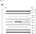
- FIGS. 3 and 4 show an embodiment of the thermal conductivity measuring apparatus 100 of the present invention.
- the heat moves vertically upward and downward from the central hot plate 110, and the guarded hot plate 120 is spaced apart from the side of the hot plate 110 to prevent loss in the lateral direction.
- an upper measuring plate 131 and a lower measuring plate 132 are provided adjacent to the hot plate in the vertical direction, and the temperatures of the respective surfaces of the upper measuring plate 131 and the lower measuring plate 132 are measured, from which the ratio of the amount of heat transferred in the vertical direction can be checked.
- an upper cooling plate 141 and a lower cooling plate 142 are disposed, and an upper cooling unit 151 and a lower cooling unit 152 are disposed adjacent thereto to thereby maintain a low temperature of the cooling plate.
- the upper battery cells 101 and the lower battery cell 102 are disposed in the upward direction and the downward direction, respectively, and the same type of battery cells should be disposed in the same direction in order to separately calculate the thermal conductivity from the lower surface to the upper surface direction and the thermal conductivity from the upper surface to the lower surface direction.
- a heat insulating member 160 is disposed, covering the side surfaces of the guarded hot plate 120, the upper measuring plates 131, the lower measuring plates 132, the upper cooling plate 141, the lower cooling plate 142, the upper cooling unit 151, the lower cooling unit 152, the upper battery cell 101, and the lower battery cell 102, in a spaced state.
- FIGS. 5 and 6 show another embodiment of the thermal conductivity measuring apparatus 200 of the present invention.
- the heat moves vertically upward and downward from the central hot plate 210, and the guarded hot plate 220 is spaced apart from the side surface of the hot plate 210 to prevent loss in the lateral direction.
- an upper measuring plate 231 and a lower measuring plate 232 are provided adjacent to the hot plate in the vertical direction, and the temperatures of the respective surfaces of the upper measuring plate 231 and the lower measuring plate 232 are measured, from which the ratio of the amount of heat transferred in the vertical direction can be checked.
- guarded measuring plates 241 and 242 are spaced apart from each side of the upper measuring plate 231 and the lower measuring plate 232, respectively.
- an upper cooling plate 251 and a lower cooling plate 252 are disposed, and an upper cooling unit 261 and a lower cooling unit 262 are disposed adjacent thereto to thereby maintain a low temperature of the cooling plate.
- the upper battery cell 201 and the lower battery cell 202 are disposed in the upward direction and the downward direction, respectively, and the same type of battery cells should be disposed in the same direction in order to separately calculate the thermal conductivity from the lower surface to the upper surface direction and the thermal conductivity from the upper surface to the lower surface direction.
- a heat insulating member 270 is disposed, covering the side surfaces of the guarded hot plate 220, the upper guarded measuring plate 241, the lower guarded measuring plate 242, the upper cooling plate 251, the lower cooling plate 252, the upper cooling unit 261, the lower cooling unit 262, the upper battery cell 201, and the lower battery cell 202, in a spaced state.
Landscapes
- Chemical & Material Sciences (AREA)
- Chemical Kinetics & Catalysis (AREA)
- Electrochemistry (AREA)
- General Chemical & Material Sciences (AREA)
- Engineering & Computer Science (AREA)
- Physics & Mathematics (AREA)
- General Physics & Mathematics (AREA)
- Analytical Chemistry (AREA)
- Health & Medical Sciences (AREA)
- Life Sciences & Earth Sciences (AREA)
- Biochemistry (AREA)
- General Health & Medical Sciences (AREA)
- Manufacturing & Machinery (AREA)
- Immunology (AREA)
- Pathology (AREA)
- Combustion & Propulsion (AREA)
- Microelectronics & Electronic Packaging (AREA)
- Investigating Or Analyzing Materials Using Thermal Means (AREA)
- Secondary Cells (AREA)
- Battery Mounting, Suspending (AREA)
Abstract
Description
- The present invention relates to an apparatus for measuring a thermal property of a pouch type battery cell, and specifically the thermal conductivity of a battery cell, and a method for measuring the thermal conductivity using the same.
- This application claims the benefit of priority based on
Korean Patent Application No. 10-2019-0072383, filed on June 18, 2019 - As the price of energy sources increases due to depletion of fossil fuels and the interest in environmental pollution increases, the demand for environmentally friendly alternative energy sources becomes an indispensable factor for future life. Especially, as technology development and demand for mobile devices are increasing, demand for secondary batteries as energy sources is rapidly increasing.
- Typically, in terms of the shape of the battery, there is a high demand for a prismatic secondary battery and a pouch-type secondary battery that can be applied to products such as mobile phones with a small thickness. In terms of materials, there is a high demand for lithium secondary batteries such as lithium ion batteries and lithium ion polymer batteries having high energy density, discharge voltage, and output stability.
- In recent years, a pouch type battery having a stack type or stack/folding type electrode assembly embedded in a pouch-shaped battery case of an aluminum laminate sheet has attracted a lot of attention due to its low manufacturing cost and small weight, and the amount used thereof is gradually increasing.
- The pouch-type battery cell accommodates a stacked or stack-folding electrode assembly manufactured by stacking a positive electrode, a separator, and a negative electrode. Each positive electrode and negative electrode are electrically connected by electrode tabs, and electrode leads that are drawn out are connected to the electrode tabs.
- The electrode assembly to which the electrode tab and the electrode lead are connected is stored in a pouch-shaped battery case, and then electrolyte is injected. A pouch type battery cell is manufactured by sealing a battery case while a part of the electrode lead is exposed to the outside.
- On the other hand, the battery case of the pouch-type battery cell is made of a pouch shape and is easy to process, so there are few restrictions according to the size or shape of the electrode assembly, and the space inside the battery cell can be efficiently used. Therefore, the pouch-type battery cell has a high energy density and can be processed in various forms, and has recently been used in mobile devices and automobile batteries in various forms. However, since the pouch-type battery cell is applied with a high energy density ranging from a small device to a large device, a temperature rise may occur inside the device. Since this temperature rise affects the performance of the device itself or causes a risk of fire, explosion, etc., it is important to grasp the flow of heat discharged from the battery cell, that is, the thermal conductivity of the battery cell.
- The thermal conductivity refers to a value indicating the degree of heat conduction in an object, and is a value obtained by dividing the amount of heat flowing in a unit time past a unit area perpendicular to the flow of heat by a difference in temperature per unit length. Therefore, it means that the higher the thermal conductivity, the better the heat is passed, and in general, metals have high thermal conductivity.
- As methods for measuring the thermal conductivity, a hot wire method, a guarded heat flow method, and a guarded hot plate method are known. Among them, the guarded hot plate method is a method for measuring the thermal conductivity of a solid sample (specimen) and is performed according to a principle of measuring the thermal conductivity by measuring the amount of heat flowing from the high temperature side to the low temperature side while accurately measuring the temperature on both sides of the sample. That is, an auxiliary hot plate called a guarded hot plate is disposed around a hot plate so that heat flow can be accurately formed in one dimension in the sample, so that the hot plate has a constant temperature. In addition, the heat should be moved in the direction perpendicular to the surface of the plate to calculate the correct thermal conductivity.
- Therefore, the hot plate and the guarded hot plate are disposed in a state that is spaced apart by a certain distance, and sometimes the space between them is filled with a material having low thermal conductivity.
- Various structures have also been studied regarding the guarded hot plate method, and in addition to a conventional method of calculating and measuring a heat flow by placing a test piece between each of the hot plate and the cooling plate, a so-called two-piece method structure, which forms a symmetrical structure up and down around the hot plate, is also used.
- However, the conventional guarded hot plate method is designed only for the measurement of a simple type of test piece made of a single material. The two-piece method also differs in that it measures the heat flow in the upward and downward directions using two test pieces, but it is the same as the conventional method, except that the accuracy is increased by averaging the thermal conductivities in the upward and downward directions, and is basically not different from the conventional method in that it targets a single material having one-sided thermal conductivity.
- However, in the case of a pouch type battery cell, unlike the test piece of a single material, it contains various materials with different properties such as positive electrode and negative electrode current collectors, separators, electrode mixtures, and battery cases, and the arrangement of each material is not evenly distributed. Hence, it is different from single material specimen.
- Therefore, since it is difficult to evaluate the thermal characteristics of a battery cell using the conventional guarded hot plate method and apparatus, a new apparatus and method are needed.
- An object of the present invention is to provide an apparatus for independently measuring the thermal conductivity of a battery cell that exhibits anisotropy in each direction and a measuring method using the same, by improving a conventional thermal conductivity measuring apparatus and measuring method in which it is difficult to measure the thermal characteristics of the battery cell.
- In order to achieve the above object, an apparatus for measuring thermal conductivity of a battery cell according to the present invention may include: a hot plate including a heating element; and a guarded hot plate surrounding the hot plate, which is spaced from a side of the hot plate.
- In addition, a measuring plate, a cooling plate, and a cooling unit may be sequentially provided at upper and lower parts respectively in a direction perpendicular to the hot plate and in a direction away from the hoy plate,
In this case, the measuring plate, the cooling plate, and the cooling unit respectively disposed in the upper and lower directions of the hot plate have a symmetrical structure about the hot plate, and one battery cell may be disposed between the upper and lower measuring plates and the cooling plate to measure thermal conductivity. - On the other hand, the guarded hot plate is for inducing the heat transfer direction of the hot plate linearly in the vertical direction on the basis of the hot plate in one dimension and is characterized in that it is maintained at a temperature equal to or higher than that of the hot plate so that the heat generated from the hot plate is not moved to the side.
- The thickness of the measuring plate is characterized in that it increases in proportion to the amount of heat generated in the hot plate. The measuring plate may have a heat tendency to a high temperature surface closer to the hot plate and a low temperature surface closer to the cooling plate. As the distance between the high temperature surface and the low temperature surface increases, heat flow tends to be uniform. However, since the heat loss increases as the thickness increases, it is necessary to adjust the thickness to an appropriate thickness according to the amount of heat.
- It is preferable that the measuring plate is made of a metal material having excellent thermal conductivity and a well-known reference value. Specifically, the measuring plate is preferably a metal or metal alloy having a thermal conductivity of 50 W/m·K or more, and more specifically, is characterized by comprising a metal material that is aluminum, copper, or an alloy thereof.
- Further, according to another embodiment of the present invention, a guarded measuring plate surrounding the measuring plate at a position spaced apart from the measuring plate on the side of the measuring plate may be further included, in which case heat loss in the measuring plate can be further reduced.
- Meanwhile, in order to further reduce the heat loss to the side of the thermal conductivity measuring apparatus, a heat insulating member comprising a heat insulating material may be provided covering the side surfaces of the guarded hot plate, the measuring plates, the cooling plates, the cooling units, and the battery cells, in a spaced state so that direct heat transfer is not achieved through the insulating member so that direct heat transfer is not achieved through the heat insulating member.
- The hot plate may be in the form of a cylinder or a cuboid. The shape of the hot plate is not limited, but in order to suppress heat loss in the lateral direction and promote one-dimensional heat transfer in the vertical direction, it may be rectangular or square, most preferably circular.
- When the battery cell thermal conductivity measuring apparatus of the present invention is used, it is possible to separately measure the thermal conductivity of the battery cells, each of which exhibits different thermal characteristics in the upward and downward directions of the battery cell. Specifically, through the following steps, it is possible to separately measure upward and downward directions in the vertical direction.
a step of calculating an amount of heat applied to the battery cell in an upward direction perpendicular to a hot plate;
a step of calculating an amount of heat applied to the battery cell in a downward direction perpendicular to the hot plate; and
a step of calculating a thermal conductivity of the battery cell by using the amount of heat applied in the upward direction and the amount of heat applied in the downward direction. - At this time, the amount of heat applied to the battery cell in the upward direction perpendicular to the hot plate may be calculated by Equation 1 below.
- (In Equation 1 above, Pup denotes an amount of heat applied to a battery cell in an upward energy integration. If heat is not efficiently discharged when high heat is generated in the secondary battery, a thermal runaway phenomenon may occur in the secondary battery itself, and it may have a bad influence depending on the thermal characteristics of the electronic device including the secondary battery. Therefore, it is very important to measure the thermal characteristics of the pouch-type battery cell.
- However, in the case of a battery cell, unlike a material made of a single material, thermal conduction occurs anisotropically, and thus it is difficult to measure characteristics with a conventional thermal conductivity measuring device. In order to solve this problem, the thermal conductivity measuring apparatus of the present invention is characterized in that it is possible to separately measure a vertical thermal conductivity from the lower surface to the upper surface of the battery cell and a vertical thermal conductivity from the upper surface to the lower surface of the battery cell.
- Through this, it is possible to accurately determine at what ratio the heat generated inside the battery cell is transferred to the upper and lower surfaces of the battery cell, and it is possible to prepare a design in a manner that optimizes the placed position and direction of the secondary battery in consideration of the thermal characteristics of the internal parts of the electronic product.
- The apparatus for measuring thermal conductivity of the present invention includes a hot plate including a heating element; and a guarded hot plate surrounding the hot plate in a state spaced from the side of the hot plate.
- In addition, a measuring plate, a cooling plate, and a cooling unit may be sequentially provided at upper and lower parts in a direction perpendicular to the hot plate, and the measuring plate, the cooling plate, and the cooling unit respectively disposed in the upper and lower directions of the hot plate have a symmetrical structure about the hot plate. Due to this structure, heat generated in the hot plate moves vertically from the hot plate to the cooling plate in the vertical direction.
- In this case, one battery cell may be disposed between the upper and lower measuring plates and the cooling plate to measure thermal conductivity.
- On the other hand, the guarded hot plate is for inducing the heat transfer direction of the hot plate linearly in the vertical direction on the basis of the hot plate in one dimension and is characterized in that it is maintained at a temperature equal to or higher than that of the hot plate so that the heat generated from the hot plate is not moved to the side. If the guarded hot plate is dropped to a lower temperature than the hot plate, it is difficult to accurately measure the thermal conductivity since heat transfer also occurs to the side due to the characteristic of moving from a high temperature to a low temperature.
- The thickness of the measuring plate is characterized in that it increases in proportion to the amount of heat generated in the hot plate. The measuring plate may have a heat tendency to a high temperature surface closer to the hot plate and a low temperature surface closer to the cooling plate. As the distance between the high temperature surface and the low temperature surface increases, heat flow tends to be uniform. That is, the thicker the thickness of the measuring plate, the more precisely the thermal characteristics can be measured. However, since the heat loss increases as the thickness increases, it is necessary to adjust the thickness to an appropriate thickness according to the amount of heat generated from the hot plate.
- It is preferable that the measuring plate comprises a metal material having excellent thermal conductivity and a well-known reference value. Specifically, as the material of the measuring plate, aluminum, copper, or alloys thereof may be selected and used. If the thermal conductivity is low, the heat loss increases as much, making it difficult to accurately measure the amount of heat.
- On the other hand, the measuring plate is a component that is a standard for measuring thermal conductivity, and when calculating thermal conductivity, the temperatures of one surface close to the hot plate and the other surface close to the cooling plate are measured.
- In addition, in order to minimize heat loss due to an increase in the thickness of the measuring plate, the measuring plate may be designed with a structure similar to that of the hot plate. According to another embodiment of the present invention, a guarded measuring plate surrounding the measuring plate at a position spaced apart from the measuring plate on the side of the measuring plate may be further included, in which case heat loss in the measuring plate can be further reduced.
- In order to further reduce the heat loss to the side of the thermal conductivity measuring apparatus, a heat insulating member comprising a heat insulating material may be provided covering the side surfaces of the guarded hot plate, the measuring plates, the cooling plates, the cooling units, and the battery cells, in a spaced state so that direct heat transfer is not achieved through the insulating member.
- When the thermal conductivity measuring apparatus includes a guarded measuring plate, a heat insulating member comprising a heat insulating material may be provided covering the side surfaces of the guarded hot plate, the guarded measuring plates, the cooling plates, the cooling units, and the battery cells, in a spaced state so that direct heat transfer is not achieved through the insulating member.
- The hot plate may be in the form of a cylinder or a cuboid. The shape of the hot plate is not limited, but in order to suppress heat loss in the lateral direction and promote one-dimensional heat transfer in the vertical direction, it may be rectangular or square, most preferably circular.
- When the battery cell thermal conductivity measuring apparatus of the present invention is used, it is possible to separately measure the thermal conductivity of the battery cells, each of which exhibits different thermal characteristics in the upward and downward directions of the battery cell. Specifically, through the following steps, it is possible to separately measure upward and downward directions in the vertical direction.
a step of calculating an amount of heat applied to the battery cell in an upward direction perpendicular to the hot plate;
a step of calculating an amount of heat applied to the battery cell in a downward direction perpendicular to the hot plate;
a step of calculating a thermal conductivity of the battery cell by using the amount of heat applied in the upward direction and the amount of heat applied in the downward direction. - Among conventional guarded hot plate methods, a two-piece method is performed based on a principle that forms a constant heat flux in the vertical direction of the main hot plate while the temperatures of the main hot plate and the auxiliary hot plate are set to be the same. Accordingly, the size of the auxiliary hot plate should be very large, and the auxiliary hot plate should be maintained at the same temperature as that of the hot plate. Also, assuming that the upper and lower test pieces have the same material and material conductivity, the calorific value is obtained as the average of the conductivity in the upward and downward directions. Therefore, it is suitable for measuring the thermal properties of an isotropic material or a heat insulating material having a uniform thermal conductivity, but the thermal conductivity of a pouch-type battery cell cannot be measured by this method.
- Therefore, in the thermal conductivity measuring apparatus of the present invention, the measuring plate is disposed above and below the hot plate to separately measure the amount of heat in the upward direction and the amount of heat in the downward direction. In addition, the hot plate should be made large in correspondence with the size of the battery cell, but the guarded hot plate may be made relatively small as the measuring plate is disposed, and the temperature of the guarded hot plate can be maintained at a temperature higher than that of the hot plate, so adjustment is easy.
- The measuring principle of the thermal conductivity measuring apparatus is as follows.
- The total amount of heat generated from the hot plate can be expressed as the product of current and voltage, which is equal to the sum of the amount of heat in the upward direction and the amount of heat in the downward direction.
- On the other hand, by using the surface temperature of the upper measuring plate and the lower measuring plate, it is possible to obtain the ratio of heat applied to each of the vertical direction. The thermal conductivities in the upward and downward directions of the battery cell can be obtained, respectively, by using this, and the ratio can also be easily calculated.
- First, the amount of heat applied to the battery cell in the upward direction perpendicular to the hot plate may be calculated by Equation 1 below.

- (In Equation 1 above, Pup denotes an amount of heat applied to a battery cell in a upward direction, T1 denotes a temperature of one surface facing a hot plate of a measuring plate placed on a top of the hot plate, T2 denotes a temperature of the other surface facing the battery cell of the measuring plate placed on the top of the hot plate, T3 denotes a temperature of one surface facing the hot plate of the measuring plate disposed under the hot plate, T4 denotes a temperature of the other surface facing the battery cell of the measuring plate placed under the hot plate, i denotes a current applied to the hot plate, and V denotes a voltage applied to the hot plate.)
- Next, the amount of heat applied to the battery cell in a downward direction perpendicular to the hot plate may be calculated by Equation 2 below.

- (In Equation 2 above, Pdown denotes an amount of heat applied to a battery cell in a downward direction, T1 denotes a temperature of one surface facing a hot plate of a measuring plate placed on a top of the hot plate, T2 denotes a temperature of the other surface facing the battery cell of the measuring plate placed on the top of the hot plate, T3 denotes a temperature of one surface facing the hot plate of the measuring plate disposed under the hot plate, T4 denotes a temperature of the other surface facing the battery cell of the measuring plate placed under the hot plate, i denotes a current applied to the hot plate, and V denotes a voltage applied to the hot plate.)
- The thermal conductivity of the battery cell may be calculated by using the calorific values respectively calculated. The thermal conductivity calculation factors according to Equations 3 and 4 below are shown below.
- First, the value of the amount of the heat applied in the upward direction, the thermal conductivity in the upward direction of the battery cell may be calculated by Equation 3 below.

- (In the Equation 3, kup denotes a vertical thermal conductivity from a bottom to a top of a battery cell, Pup denotes an amount of heat applied to the battery cell in an upward direction, Ltop denotes a thickness of a battery cell, A denotes a unit area for measuring an amount of heat, TH denotes a temperature at a bottom of a battery cell close to a hot plate, and TC denotes a temperature at a top of a battery cell close to a cooling plate.)
- Using the value of the amount of the heat applied in the downward direction, the thermal conductivity in the downward direction of the battery cell may be calculated by Equation 4 below.

- (In the Equation 4, kdown denotes a vertical thermal conductivity from a top to a bottom of a battery cell, Pdown denotes an amount of heat applied to the battery cell in a downward direction, Lbottom denotes a thickness of a battery cell, A denotes a unit area for measuring an amount of heat, T'H denotes a temperature at a top of a battery cell close to a hot plate, and T'C denotes a temperature at a bottom of a battery cell close to a cooling plate.)
- The thermal conductivity of an anisotropic battery cell can be calculated separately for each direction by using the kup and kdown values, and the rate at which heat is transferred in each direction is also easily seen.
- Hereinafter, the structure of the thermal conductivity measuring apparatus of the present invention will be described in more detail with reference to each drawing.
-
FIG. 1 shows a conventional thermalconductivity measuring apparatus 10, which is provided with ahot plate 11, a guardedhot plate 12, a measuringplate 13, a guardedplate 14, a coolingplate 16, aheat insulating material 17, a guardedplate 18. Herein, atest piece 15 is disposed on thecooling plate 16. Since the heat generated from thehot plate 11 moves vertically towards the coolingplate 16, heat transfer from the top to the bottom of thetest piece 15 occurs. Therefore, this method is applicable only to isotropic materials. In addition, since the heat loss to the side is large, it is possible to grasp the approximate thermal characteristics, but precise measurement is impossible. In addition, the measuringplate 13 does not directly measure the amount of heat generated in thehot plate 11, but serves as a heat insulating material for preventing heat loss in measuring the amount of heat. Therefore, the measuringapparatus 10 ofFIG. 1 does not measure the surface temperature in the vertical direction of the measuringplate 13. On the other hand, the measuring plate provided in the measuring apparatus of the present invention is provided in a vertically symmetrical structure unlike a conventional measuring apparatus, and it does not serve as a heat insulating material, but it is used to calculate the amount of heat that moves in the vertical direction of the hot plate as the surface temperature of the measuring plate is directly measured. -
FIG. 2 shows another conventional thermalconductivity measuring apparatus 20 which has been further improved compared to the thermalconductivity measuring apparatus 10 ofFIG. 1 . It includes ahot plate 21, a measuringplate 22, a measuringinstrument 23, a guardedplate 24, a guardedhot plate 25, a coolingplate 27, a coolingunit 28 and aheat insulating member 29. Atest piece 26 is disposed on thecooling plate 27, and the heat transfer occurs from top to bottom. The heat loss is more suppressed than the thermalconductivity measuring device 10 ofFIG. 1 . but likewise, only the thermal conductivity in one direction can be measured, so it is not suitable for measuring the thermal conductivity of the battery cell. -
FIGS. 3 and4 show an embodiment of the thermalconductivity measuring apparatus 100 of the present invention. The heat moves vertically upward and downward from the centralhot plate 110, and the guardedhot plate 120 is spaced apart from the side of thehot plate 110 to prevent loss in the lateral direction. In addition, anupper measuring plate 131 and alower measuring plate 132 are provided adjacent to the hot plate in the vertical direction, and the temperatures of the respective surfaces of theupper measuring plate 131 and thelower measuring plate 132 are measured, from which the ratio of the amount of heat transferred in the vertical direction can be checked. Next, anupper cooling plate 141 and alower cooling plate 142 are disposed, and anupper cooling unit 151 and alower cooling unit 152 are disposed adjacent thereto to thereby maintain a low temperature of the cooling plate. Theupper battery cells 101 and thelower battery cell 102 are disposed in the upward direction and the downward direction, respectively, and the same type of battery cells should be disposed in the same direction in order to separately calculate the thermal conductivity from the lower surface to the upper surface direction and the thermal conductivity from the upper surface to the lower surface direction. Also, aheat insulating member 160 is disposed, covering the side surfaces of the guardedhot plate 120, theupper measuring plates 131, thelower measuring plates 132, theupper cooling plate 141, thelower cooling plate 142, theupper cooling unit 151, thelower cooling unit 152, theupper battery cell 101, and thelower battery cell 102, in a spaced state. -
FIGS. 5 and6 show another embodiment of the thermalconductivity measuring apparatus 200 of the present invention. The heat moves vertically upward and downward from the centralhot plate 210, and the guardedhot plate 220 is spaced apart from the side surface of thehot plate 210 to prevent loss in the lateral direction. In addition, anupper measuring plate 231 and alower measuring plate 232 are provided adjacent to the hot plate in the vertical direction, and the temperatures of the respective surfaces of theupper measuring plate 231 and thelower measuring plate 232 are measured, from which the ratio of the amount of heat transferred in the vertical direction can be checked. In addition, guarded measuringplates upper measuring plate 231 and thelower measuring plate 232, respectively. Through this, it is possible to further reduce the heat loss in the measuring plate, and it is possible to maintain the heat transfer characteristics uniformly. Next, anupper cooling plate 251 and alower cooling plate 252 are disposed, and anupper cooling unit 261 and alower cooling unit 262 are disposed adjacent thereto to thereby maintain a low temperature of the cooling plate. Theupper battery cell 201 and thelower battery cell 202 are disposed in the upward direction and the downward direction, respectively, and the same type of battery cells should be disposed in the same direction in order to separately calculate the thermal conductivity from the lower surface to the upper surface direction and the thermal conductivity from the upper surface to the lower surface direction. Also, aheat insulating member 270 is disposed, covering the side surfaces of the guardedhot plate 220, the upper guarded measuringplate 241, the lower guardedmeasuring plate 242, theupper cooling plate 251, thelower cooling plate 252, theupper cooling unit 261, thelower cooling unit 262, theupper battery cell 201, and thelower battery cell 202, in a spaced state. -
- 10: thermal conductivity measuring apparatus
- 11: hot plate
- 12: guarded hot plate
- 13: measuring plate
- 14: guarded plate
- 15: test piece
- 16: cooling plate
- 17: heat insulating material
- 18: guarded plate
- 20: thermal conductivity measuring apparatus
- 21: hot plate
- 22: measuring plate
- 23: measuring instrument
- 24: guarded plate
- 25: guarded hot plate
- 26: test piece
- 27: cooling plate
- 28: cooling unit
- 29: heat insulating material
- 100: thermal conductivity measuring apparatus
- 101: upper battery cell
- 102: lower battery cell
- 110: hot plate
- 120: guarded hot plate
- 131: upper measuring plate
- 132: lower measuring plate
- 141: upper cooling plate
- 142: lower cooling plate
- 151: upper cooling unit
- 152: lower cooling unit
- 160: heat insulating member
- 200: thermal conductivity measuring apparatus
- 201: upper battery cell
- 202: lower battery cell
- 210: hot plate
- 220: guarded hot plate
- 231: upper measuring plate
- 232: lower measuring plate
- 241: upper guarded measuring plate
- 242: lower guarded measuring plate
- 251: upper cooling plate
- 252: lower cooling plate
- 261: upper cooling unit
- 262: lower cooling unit
- 270: heat insulating member
Claims (12)
- An apparatus for measuring thermal conductivity of a battery cell, the apparatus comprising:a hot plate including a heating element; anda guarded hot plate surrounding the hot plate, which is spaced from a side of the hot plate,wherein the apparatus has symmetrical structure about the hot plate by sequentially including a measuring plate, a cooling plate, and a cooling unit on an upper part and a lower part of the hot plate, respectively, in a direction perpendicular to the hot plate, and in a direction away from the hot plate, andwherein a battery cell is disposed between the cooling plate and the measuring plate of the upper part and the lower part, respectively.
- The apparatus of claim 1, wherein the guarded hot plate is maintained at a temperature equal to or higher than the hot plate.
- The apparatus of claim 1, wherein a thickness of the measuring plate increases in proportion to an amount of heat generated in the hot plate.
- The apparatus of claim 1, wherein the measuring plate comprises aluminum, copper or an alloy thereof.
- The apparatus of claim 1, further comprising a guarded measuring plate surrounding the measuring plate in a position spaced apart from the measuring plate on a side of the measuring plate.
- The apparatus of claim 1, wherein the hot plate is in a form of a cylinder or cuboid.
- The apparatus of claim 1, further comprising a heat insulating member covering the side surfaces of the guarded hot plate, the measuring plates, the cooling plates, the cooling units, and the battery cells, in a spaced state.
- A method for measuring thermal conductivity of a battery cell by using the apparatus of claim 1, comprising:calculating an amount of heat applied to the battery cell in an upward direction perpendicular to a hot plate;calculating an amount of heat applied to the battery cell in a downward direction perpendicular to the hot plate; andcalculating a thermal conductivity of the battery cell using the amount of heat applied in the upward direction and the amount of heat applied in the downward direction.
- The method of claim 8, wherein the amount of heat applied to the battery cell in the upward direction perpendicular to the hot plate is calculated by Equation 1 below:
 Pup denotes an amount of heat applied to a battery cell in an upward direction, T1 denotes a temperature of one surface facing a hot plate of a measuring plate placed on a top of the hot plate,T2 denotes a temperature of the other surface facing the battery cell of the measuring plate placed on the top of the hot plate,T3 denotes a temperature of one surface facing the hot plate of the measuring plate disposed under the hot plate,T4 denotes a temperature of the other surface facing the battery cell of the measuring plate placed under the hot plate,i denotes a current applied to the hot plate, andV denotes a voltage applied to the hot plat.
 - The method of claim 8, wherein the amount of heat applied to the battery cell in the downward direction perpendicular to the hot plate is calculated by Equation 2 below:
 T1 denotes a temperature of one surface facing a hot plate of a measuring plate placed on a top of the hot plate,T2 denotes a temperature of the other surface facing the battery cell of the measuring plate placed on the top of the hot plate,T3 denotes a temperature of one surface facing the hot plate of the measuring plate disposed under the hot plate,T4 denotes a temperature of the other surface facing the battery cell of the measuring plate placed under the hot plate,i denotes a current applied to the hot plate, andV denotes a voltage applied to the hot plate.
 - The method of claim 8, wherein the thermal conductivity in the upward direction of the battery cell is calculated by Equation 3 below:
 kup denotes a vertical thermal conductivity from a bottom to a top of a battery cell,Pup denotes an amount of heat applied to the battery cell in an upward direction,Ltop denotes a thickness of a battery cell,A denotes a unit area for measuring an amount of heat,TH denotes a temperature at a bottom of a battery cell close to a hot plate, andTC denotes a temperature at a top of a battery cell close to a cooling plate.
 - The method of claim 8, wherein the thermal conductivity in the downward direction of the battery cell is calculated by Equation 4 below:
 kdown denotes a vertical thermal conductivity from a top to a bottom of a battery cell,Pdown denotes an amount of heat applied to the battery cell in a downward direction,Lbottom denotes a thickness of a battery cell,A denotes a unit area for measuring an amount of heat,T'H denotes a temperature at a top of a battery cell close to a hot plate, andT'C denotes a temperature at a bottom of a battery cell close to a cooling plate.
Applications Claiming Priority (2)
| Application Number | Priority Date | Filing Date | Title |
|---|---|---|---|
| KR1020190072383A KR102773587B1 (en) | 2019-06-18 | 2019-06-18 | Apparatus and Method for Measuring Thermal Conductivity of Battery Cell |
| PCT/KR2020/007270 WO2020256316A1 (en) | 2019-06-18 | 2020-06-04 | Battery cell thermal conductivity measurement device and battery cell thermal conductivity measurement method using same |
Publications (3)
| Publication Number | Publication Date |
|---|---|
| EP3855551A1 true EP3855551A1 (en) | 2021-07-28 |
| EP3855551A4 EP3855551A4 (en) | 2021-12-08 |
| EP3855551B1 EP3855551B1 (en) | 2025-12-17 |
Family
ID=74037298
Family Applications (1)
| Application Number | Title | Priority Date | Filing Date |
|---|---|---|---|
| EP20825793.1A Active EP3855551B1 (en) | 2019-06-18 | 2020-06-04 | Battery cell thermal conductivity measurement method |
Country Status (8)
| Country | Link |
|---|---|
| US (1) | US11978865B2 (en) |
| EP (1) | EP3855551B1 (en) |
| JP (1) | JP7191217B2 (en) |
| KR (1) | KR102773587B1 (en) |
| CN (1) | CN112997070B (en) |
| ES (1) | ES3058838T3 (en) |
| PL (1) | PL3855551T3 (en) |
| WO (1) | WO2020256316A1 (en) |
Families Citing this family (4)
| Publication number | Priority date | Publication date | Assignee | Title |
|---|---|---|---|---|
| CN111879811A (en) * | 2020-06-22 | 2020-11-03 | 国联汽车动力电池研究院有限责任公司 | Battery parameter measurement equipment and method |
| JP7289870B2 (en) * | 2021-04-08 | 2023-06-12 | プライムプラネットエナジー&ソリューションズ株式会社 | heat measurement device |
| KR102890333B1 (en) | 2023-10-20 | 2025-11-24 | 비나텍 주식회사 | Pouch Typed Cell For Preventing Thermal Shock |
| CN120577353B (en) * | 2025-08-05 | 2025-10-17 | 中国计量大学 | Lithium battery temperature heating parameter measurement method and device |
Family Cites Families (29)
| Publication number | Priority date | Publication date | Assignee | Title |
|---|---|---|---|---|
| PL139300B1 (en) * | 1983-04-27 | 1987-01-31 | Pan Ct Badan Molekularnych I M | Method of determination of thermal conductivity and heat storage capacity of materials and apparatus therefor |
| JP2614062B2 (en) * | 1987-12-25 | 1997-05-28 | 財団法人建材試験センター | Thermal conductivity measuring device based on the direct plate method |
| JP3324858B2 (en) | 1994-01-26 | 2002-09-17 | 英弘精機株式会社 | Apparatus and method for measuring thermal conductivity of insulation wrapped with skin material |
| US6086362A (en) * | 1998-05-20 | 2000-07-11 | Applied Komatsu Technology, Inc. | Multi-function chamber for a substrate processing system |
| US6218843B1 (en) * | 2000-06-23 | 2001-04-17 | The Aerospace Corporation | Zero gravity simulator for testing battery cells |
| JP2002166167A (en) | 2000-11-30 | 2002-06-11 | Unitika Ltd | Activated carbon sheet for adsorbing lower aldehyde or the like and method for producing the same |
| KR200334651Y1 (en) * | 2003-08-22 | 2003-11-28 | 송국섭 | A measuring instrument of heat conductivity using thermoelectric modules |
| JP4083127B2 (en) * | 2004-02-10 | 2008-04-30 | ニチアス株式会社 | Thermal conductivity measuring device and thermal conductivity measuring method |
| DE102007039365A1 (en) * | 2007-08-21 | 2009-02-26 | GMF-Gesellschaft für Motoren- und Fahrzeugtechnik mbH | Thermal resistance determining device for determining thermal resistance of sample, has sample retainer retaining sample in test chamber in such manner that sample is isolated against thermal conduction |
| KR101092894B1 (en) | 2009-07-31 | 2011-12-12 | 한국과학기술원 | Apparatus for measuring coefficient of heat transfer |
| JP2012032231A (en) | 2010-07-29 | 2012-02-16 | Nichias Corp | Thermal conductivity measuring apparatus |
| KR20120063687A (en) * | 2010-12-08 | 2012-06-18 | 현대모비스 주식회사 | Battery module temperature measurement device |
| JP5911218B2 (en) | 2011-06-30 | 2016-04-27 | ニチアス株式会社 | Thermal conductivity measuring method and thermal conductivity measuring device |
| JP2013019712A (en) * | 2011-07-08 | 2013-01-31 | Palmetrics Co Ltd | Specific heat measurement device and specific heat measurement method |
| KR101302750B1 (en) * | 2011-09-09 | 2013-08-30 | 한국표준과학연구원 | Apparatus for evaluating a thermoelectric device |
| KR101276659B1 (en) * | 2011-09-09 | 2013-06-19 | 한국표준과학연구원 | Method for evaluating a thermoelectric figure-of-merit of thermoelectric device |
| JP5827097B2 (en) | 2011-10-17 | 2015-12-02 | ニチアス株式会社 | Thermal conductivity measurement method |
| US20140142884A1 (en) * | 2012-11-19 | 2014-05-22 | King Fahd University Of Petroleum And Minerals | System for measuring thermal conductance |
| CN204228639U (en) | 2014-08-07 | 2015-03-25 | 中钢集团洛阳耐火材料研究院有限公司 | A high temperature protection hot plate heat conduction instrument |
| US10041894B1 (en) * | 2015-09-09 | 2018-08-07 | Amazon Technologies, Inc. | Thermal conductivity measurement of anisotropic substrates |
| KR101706251B1 (en) * | 2015-11-09 | 2017-02-14 | 부산대학교 산학협력단 | Apparatus and method for measuring thermal conductivity |
| CN106053527B (en) | 2016-07-04 | 2019-02-26 | 中国第一汽车股份有限公司 | A method for simultaneously testing the anisotropic thermal diffusivity of power batteries |
| CN106198618B (en) * | 2016-07-18 | 2019-03-15 | 金龙联合汽车工业(苏州)有限公司 | Electrodes of lithium-ion batteries thermal conductivity consistency detection device and method |
| KR101767445B1 (en) * | 2016-07-26 | 2017-08-11 | 한국표준과학연구원 | Guarded hot plate apparatus and manufacturing method thereof |
| CN106872898B (en) * | 2017-02-06 | 2020-03-17 | 中国第一汽车股份有限公司 | Rapid testing method for thermal resistance of single interface of power battery |
| JP6535367B2 (en) * | 2017-05-30 | 2019-06-26 | ミネベアミツミ株式会社 | Temperature measurement device using strain gauge |
| CN110785641B (en) * | 2017-06-02 | 2021-07-27 | 卡尔巴科特公司 | Calorimeter |
| JP2019109980A (en) | 2017-12-15 | 2019-07-04 | 株式会社日立ハイテクノロジーズ | Plasma processing apparatus |
| CN108775971A (en) | 2018-09-10 | 2018-11-09 | 中国科学院工程热物理研究所 | A kind of measurement method of temperature measuring equipment and specific heat capacity and thermal conductivity |
-
2019
- 2019-06-18 KR KR1020190072383A patent/KR102773587B1/en active Active
-
2020
- 2020-06-04 EP EP20825793.1A patent/EP3855551B1/en active Active
- 2020-06-04 JP JP2021524443A patent/JP7191217B2/en active Active
- 2020-06-04 WO PCT/KR2020/007270 patent/WO2020256316A1/en not_active Ceased
- 2020-06-04 US US17/289,197 patent/US11978865B2/en active Active
- 2020-06-04 CN CN202080005947.5A patent/CN112997070B/en active Active
- 2020-06-04 ES ES20825793T patent/ES3058838T3/en active Active
- 2020-06-04 PL PL20825793.1T patent/PL3855551T3/en unknown
Also Published As
| Publication number | Publication date |
|---|---|
| KR20200144381A (en) | 2020-12-29 |
| JP2022506834A (en) | 2022-01-17 |
| US20210344056A1 (en) | 2021-11-04 |
| EP3855551A4 (en) | 2021-12-08 |
| ES3058838T8 (en) | 2026-04-16 |
| ES3058838T3 (en) | 2026-03-13 |
| CN112997070B (en) | 2024-09-27 |
| JP7191217B2 (en) | 2022-12-16 |
| CN112997070A (en) | 2021-06-18 |
| US11978865B2 (en) | 2024-05-07 |
| KR102773587B1 (en) | 2025-02-27 |
| EP3855551B1 (en) | 2025-12-17 |
| WO2020256316A1 (en) | 2020-12-24 |
| PL3855551T3 (en) | 2026-04-13 |
Similar Documents
| Publication | Publication Date | Title |
|---|---|---|
| EP3855551B1 (en) | Battery cell thermal conductivity measurement method | |
| Ghalkhani et al. | Electrochemical–thermal model of pouch-type lithium-ion batteries | |
| Zhao et al. | Thermal behavior study of discharging/charging cylindrical lithium-ion battery module cooled by channeled liquid flow | |
| Cavalheiro et al. | Effects of nonuniform temperature distribution on degradation of lithium-ion batteries | |
| Sturm et al. | Impact of electrode and cell design on fast charging capabilities of cylindrical lithium-ion batteries | |
| EP3442073B1 (en) | Battery cell capable of measuring internal temperature | |
| Kang et al. | How electrode thicknesses influence performance of cylindrical lithium-ion batteries | |
| An et al. | Numerical modeling and analysis of thermal behavior and Li+ transport characteristic in lithium-ion battery | |
| Lundgren et al. | Thermal management of large-format prismatic lithium-ion battery in PHEV application | |
| KR101874181B1 (en) | Battery assembly | |
| Rheinfeld et al. | Impact of cell size and format on external short circuit behavior of lithium-ion cells at varying cooling conditions: modeling and simulation | |
| CN111684646A (en) | Explosion pressure prediction system for medium and large monomer modules and method for predicting explosion pressure of medium and large monomer modules | |
| CN109565088B (en) | Electric storage element state estimation device and electric storage element state estimation method | |
| JP6396812B2 (en) | Charging rate estimation system | |
| Wang et al. | Experimental investigation on the feasibility of heat pipe-based thermal management system to prevent thermal runaway propagation | |
| Huo et al. | Electrochemical–thermal modeling for a ternary lithium ion battery during discharging and driving cycle testing | |
| US20140212711A1 (en) | Switching board of novel structure, and battery module containing the same | |
| Zhang et al. | Numerical study on thermal characteristics under external short circuit for Li|| Bi liquid metal batteries | |
| Kraft et al. | Implications of the heat generation of LMR-NCM on the thermal behavior of large-format lithium-ion batteries | |
| Zhao et al. | Cathode chemistries and electrode parameters affecting the fast charging performance of Li-ion batteries | |
| US20230352752A1 (en) | Battery cell jig comprising spacer laminate, apparatus comprising same for measuring volume of battery cell, and method for measuring volume of battery cell using same | |
| US20230073871A1 (en) | Battery cell jig comprising spacer, apparatus comprising same for measuring volume of battery cell, and method for measuring volume of battery cell using same | |
| Gibellini et al. | Dimensional changes in automotive pouch li-ion cells: A combined thermo-mechanical/electrochemical study | |
| Mörtel et al. | Smart Cells-Battery monitoring via internal sensors | |
| CN114447443B (en) | Electrochemical device, method for manufacturing electrochemical device, and electrical equipment |
Legal Events
| Date | Code | Title | Description |
|---|---|---|---|
| STAA | Information on the status of an ep patent application or granted ep patent |
Free format text: STATUS: THE INTERNATIONAL PUBLICATION HAS BEEN MADE |
|
| PUAI | Public reference made under article 153(3) epc to a published international application that has entered the european phase |
Free format text: ORIGINAL CODE: 0009012 |
|
| STAA | Information on the status of an ep patent application or granted ep patent |
Free format text: STATUS: REQUEST FOR EXAMINATION WAS MADE |
|
| 17P | Request for examination filed |
Effective date: 20210423 |
|
| AK | Designated contracting states |
Kind code of ref document: A1 Designated state(s): AL AT BE BG CH CY CZ DE DK EE ES FI FR GB GR HR HU IE IS IT LI LT LU LV MC MK MT NL NO PL PT RO RS SE SI SK SM TR |
|
| A4 | Supplementary search report drawn up and despatched |
Effective date: 20211109 |
|
| RIC1 | Information provided on ipc code assigned before grant |
Ipc: G01N 25/20 20060101ALI20211103BHEP Ipc: G01N 25/18 20060101ALI20211103BHEP Ipc: H01M 10/42 20060101AFI20211103BHEP |
|
| RAP1 | Party data changed (applicant data changed or rights of an application transferred) |
Owner name: LG ENERGY SOLUTION LTD. |
|
| RAP3 | Party data changed (applicant data changed or rights of an application transferred) |
Owner name: LG ENERGY SOLUTION, LTD. |
|
| DAV | Request for validation of the european patent (deleted) | ||
| DAX | Request for extension of the european patent (deleted) | ||
| STAA | Information on the status of an ep patent application or granted ep patent |
Free format text: STATUS: EXAMINATION IS IN PROGRESS |
|
| 17Q | First examination report despatched |
Effective date: 20230124 |
|
| REG | Reference to a national code |
Ref country code: DE Free format text: PREVIOUS MAIN CLASS: H01M0010420000 Ipc: G01R0031360000 Ref country code: DE Ref legal event code: R079 Ref document number: 602020064132 Country of ref document: DE Free format text: PREVIOUS MAIN CLASS: H01M0010420000 Ipc: G01R0031360000 |
|
| GRAP | Despatch of communication of intention to grant a patent |
Free format text: ORIGINAL CODE: EPIDOSNIGR1 |
|
| STAA | Information on the status of an ep patent application or granted ep patent |
Free format text: STATUS: GRANT OF PATENT IS INTENDED |
|
| RIC1 | Information provided on ipc code assigned before grant |
Ipc: G01R 31/36 20200101AFI20250620BHEP Ipc: G01N 25/18 20060101ALI20250620BHEP Ipc: G01N 25/20 20060101ALI20250620BHEP Ipc: H01M 10/42 20060101ALI20250620BHEP Ipc: H01M 10/48 20060101ALI20250620BHEP Ipc: H01M 10/6551 20140101ALI20250620BHEP |
|
| INTG | Intention to grant announced |
Effective date: 20250709 |
|
| GRAJ | Information related to disapproval of communication of intention to grant by the applicant or resumption of examination proceedings by the epo deleted |
Free format text: ORIGINAL CODE: EPIDOSDIGR1 |
|
| STAA | Information on the status of an ep patent application or granted ep patent |
Free format text: STATUS: EXAMINATION IS IN PROGRESS |
|
| GRAP | Despatch of communication of intention to grant a patent |
Free format text: ORIGINAL CODE: EPIDOSNIGR1 |
|
| STAA | Information on the status of an ep patent application or granted ep patent |
Free format text: STATUS: GRANT OF PATENT IS INTENDED |
|
| INTC | Intention to grant announced (deleted) | ||
| INTG | Intention to grant announced |
Effective date: 20250902 |
|
| P01 | Opt-out of the competence of the unified patent court (upc) registered |
Free format text: CASE NUMBER: UPC_APP_4868_3855551/2025 Effective date: 20250827 |
|
| GRAS | Grant fee paid |
Free format text: ORIGINAL CODE: EPIDOSNIGR3 |
|
| GRAA | (expected) grant |
Free format text: ORIGINAL CODE: 0009210 |
|
| STAA | Information on the status of an ep patent application or granted ep patent |
Free format text: STATUS: THE PATENT HAS BEEN GRANTED |
|
| AK | Designated contracting states |
Kind code of ref document: B1 Designated state(s): AL AT BE BG CH CY CZ DE DK EE ES FI FR GB GR HR HU IE IS IT LI LT LU LV MC MK MT NL NO PL PT RO RS SE SI SK SM TR |
|
| REG | Reference to a national code |
Ref country code: CH Ref legal event code: F10 Free format text: ST27 STATUS EVENT CODE: U-0-0-F10-F00 (AS PROVIDED BY THE NATIONAL OFFICE) Effective date: 20251217 Ref country code: GB Ref legal event code: FG4D |
|
| REG | Reference to a national code |
Ref country code: DE Ref legal event code: R096 Ref document number: 602020064132 Country of ref document: DE |
|
| REG | Reference to a national code |
Ref country code: SE Ref legal event code: TRGR |
|
| REG | Reference to a national code |
Ref country code: ES Ref legal event code: FG2A Ref document number: 3058838 Country of ref document: ES Kind code of ref document: T3 Effective date: 20260313 |
|
| REG | Reference to a national code |
Ref country code: LT Ref legal event code: MG9D |
|
| PG25 | Lapsed in a contracting state [announced via postgrant information from national office to epo] |
Ref country code: NO Free format text: LAPSE BECAUSE OF FAILURE TO SUBMIT A TRANSLATION OF THE DESCRIPTION OR TO PAY THE FEE WITHIN THE PRESCRIBED TIME-LIMIT Effective date: 20260317 |
|
| PG25 | Lapsed in a contracting state [announced via postgrant information from national office to epo] |
Ref country code: HR Free format text: LAPSE BECAUSE OF FAILURE TO SUBMIT A TRANSLATION OF THE DESCRIPTION OR TO PAY THE FEE WITHIN THE PRESCRIBED TIME-LIMIT Effective date: 20251217 Ref country code: FI Free format text: LAPSE BECAUSE OF FAILURE TO SUBMIT A TRANSLATION OF THE DESCRIPTION OR TO PAY THE FEE WITHIN THE PRESCRIBED TIME-LIMIT Effective date: 20251217 |
|
| PG25 | Lapsed in a contracting state [announced via postgrant information from national office to epo] |
Ref country code: RS Free format text: LAPSE BECAUSE OF FAILURE TO SUBMIT A TRANSLATION OF THE DESCRIPTION OR TO PAY THE FEE WITHIN THE PRESCRIBED TIME-LIMIT Effective date: 20260317 |
|
| REG | Reference to a national code |
Ref country code: NL Ref legal event code: MP Effective date: 20251217 |
|
| PG25 | Lapsed in a contracting state [announced via postgrant information from national office to epo] |
Ref country code: LV Free format text: LAPSE BECAUSE OF FAILURE TO SUBMIT A TRANSLATION OF THE DESCRIPTION OR TO PAY THE FEE WITHIN THE PRESCRIBED TIME-LIMIT Effective date: 20251217 |
|
| PG25 | Lapsed in a contracting state [announced via postgrant information from national office to epo] |
Ref country code: BG Free format text: LAPSE BECAUSE OF FAILURE TO SUBMIT A TRANSLATION OF THE DESCRIPTION OR TO PAY THE FEE WITHIN THE PRESCRIBED TIME-LIMIT Effective date: 20251217 |