EP3855518A2 - Thermoelectric conversion module - Google Patents
Thermoelectric conversion module Download PDFInfo
- Publication number
- EP3855518A2 EP3855518A2 EP20217979.2A EP20217979A EP3855518A2 EP 3855518 A2 EP3855518 A2 EP 3855518A2 EP 20217979 A EP20217979 A EP 20217979A EP 3855518 A2 EP3855518 A2 EP 3855518A2
- Authority
- EP
- European Patent Office
- Prior art keywords
- thermoelectric conversion
- type
- conversion module
- type thermoelectric
- cross
- Prior art date
- Legal status (The legal status is an assumption and is not a legal conclusion. Google has not performed a legal analysis and makes no representation as to the accuracy of the status listed.)
- Granted
Links
Images



Classifications
-
- H—ELECTRICITY
- H10—SEMICONDUCTOR DEVICES; ELECTRIC SOLID-STATE DEVICES NOT OTHERWISE PROVIDED FOR
- H10N—ELECTRIC SOLID-STATE DEVICES NOT OTHERWISE PROVIDED FOR
- H10N10/00—Thermoelectric devices comprising a junction of dissimilar materials, i.e. devices exhibiting Seebeck or Peltier effects
- H10N10/10—Thermoelectric devices comprising a junction of dissimilar materials, i.e. devices exhibiting Seebeck or Peltier effects operating with only the Peltier or Seebeck effects
- H10N10/17—Thermoelectric devices comprising a junction of dissimilar materials, i.e. devices exhibiting Seebeck or Peltier effects operating with only the Peltier or Seebeck effects characterised by the structure or configuration of the cell or thermocouple forming the device
-
- H—ELECTRICITY
- H10—SEMICONDUCTOR DEVICES; ELECTRIC SOLID-STATE DEVICES NOT OTHERWISE PROVIDED FOR
- H10N—ELECTRIC SOLID-STATE DEVICES NOT OTHERWISE PROVIDED FOR
- H10N10/00—Thermoelectric devices comprising a junction of dissimilar materials, i.e. devices exhibiting Seebeck or Peltier effects
- H10N10/80—Constructional details
- H10N10/85—Thermoelectric active materials
- H10N10/851—Thermoelectric active materials comprising inorganic compositions
- H10N10/8556—Thermoelectric active materials comprising inorganic compositions comprising compounds containing germanium or silicon
Definitions
- thermoelectric conversion module The present disclosure relates to a thermoelectric conversion module.
- thermoelectric conversion module for cogeneration that can improve power efficiency by 5% (for example, output of 10 kW/m 2 in the cogeneration of 35kW class) from exhaust heat (from 300°C to 600°C) of cogeneration.
- 5% for example, output of 10 kW/m 2 in the cogeneration of 35kW class
- exhaust heat from 300°C to 600°C
- An improvement of about 3% in a gas engine installed in the cogeneration is possible by improving the engine, but further improvement requires other improvement technologies.
- thermoelectric conversion module is configured by combining a p-type thermoelectric conversion material and an n-type thermoelectric conversion material.
- a thermoelectric conversion module in order to obtain high thermoelectric conversion characteristics in the thermoelectric conversion module, it is obviously desired to obtain a high performance index ZT for both p-type and n-type thermoelectric conversion materials.
- performance can be maximized by optimizing the structure in accordance with element characteristics peculiar to the materials used.
- p-type t: 1 - t, where 0.42 ⁇ t ⁇ 0.6 (see paragraph [0059] of Patent Literature 1).
- thermoelectric element a material system of the thermoelectric element is not shown, the cross-sectional area ratio t is defined as 0.6 ⁇ t ⁇ 0.74.
- a power generation output changes depending on a module structure (element area and element thickness) and a heat source surface area which is a factor of a heat transfer capacity of the heat exchange part.
- thermoelectric conversion module has not been optimized, and a maximum power output has not yet been obtained.
- thermoelectric conversion module that further improves power efficiency from exhaust heat of cogeneration.
- thermoelectric conversion module configured in multiple pairs, the thermoelectric conversion module including a p-type thermoelectric conversion material and an n-type thermoelectric conversion material, each of which is a silicide material based on a binary system, and heat supply units disposed on an upper surface and a lower surface in a thickness direction of the thermoelectric conversion module, configured to impart a temperature difference to the thermoelectric conversion module, and configured to supply heat source supplying heat for power generation by Seebeck effect of the p-type and n-type thermoelectric conversion materials and cooling source discharging heat, the p-type and n-type thermoelectric conversion materials being characterized by having a cross-sectional area ratio t satisfying:
- thermoelectric conversion module having a maximum power output exceeding 10 kW/m 2 (equivalent to a conversion efficiency of 5%).
- the embodiment of the present disclosure is based on our binary silicide material (which is distinctively different from Patent Literatures 1 and 2). Further, in the present embodiment, the structure is optimized in consideration of heat transfer regarding an outlet of a heat flow (which is different from Patent Literature 1).
- the cross-sectional area ratio of the p-type thermoelectric conversion element and the n-type thermoelectric conversion element manufactured from a silicide material based on the binary system configuring the thermoelectric conversion module is optimized and the cross-sectional area of the electrodes at the outlet of the heat flow is optimized, thereby achieving a maximum power output (the power output of the thermoelectric conversion module using a silicide material based on the binary system is maximized).
- Fig. 1 is a diagram showing a configuration example of a single-pair thermoelectric conversion module 100.
- Fig. 2 is a diagram showing a configuration example of an electrical equivalent circuit of the single-pair thermoelectric conversion module 100.
- Equation (4) an internal resistances r p and r n can be obtained from Equation (4).
- r p ⁇ 0 L ⁇ p x A p d x
- r n ⁇ 0 L ⁇ n x A n d x
- ⁇ p and ⁇ n are electrical resistivities in a length direction of the p-type and n-type thermoelectric conversion elements, respectively.
- generated voltages V p and V n can be obtained from a temperature integration of Seebeck coefficients (S p and S n ) as in Equation (5).
- S p and S n Seebeck coefficients
- h p is the heat transfer coefficient at the interface between a high temperature electrode and the p-type thermoelectric conversion element
- h p * is the effective heat transfer coefficient of a low temperature electrode
- h n and h n * are defined similarly.
- Equation (7) can be approximately represented by the following Equation (8).
- Equation (8) [Math. 8] h p * ⁇ h ⁇ A p ⁇ A p h n * ⁇ h ⁇ A n ⁇ A n
- Equation (10) is the heat transfer coefficient of water cooling
- a p and A n are the cross-sectional areas of the element
- a p ' and A n ' are surface areas of a water cooling part.
- temperature characteristics can be approximated linearly. From Equation (9) using the symbol ⁇ > indicating an average, the internal resistance and the generated voltage are represented as in Equation (10). [Math.
- Equation (12) the maximum power output P max of power generation is represented as in Equation (11), and the maximum power output per unit area is represented as in Equation (12).
- P max A tot ⁇ ⁇ T 2 4 v L g t
- ⁇ is a filling factor and is defined as in Equation (13). [Math. 13] ⁇ ⁇ A A tot
- Equation (14) an area A is represented as in Equation (14), and each A p and A n can be represented as in Equation (15) by using the cross-sectional area ratio t.
- A A p + A n
- a p tA
- a n 1 ⁇ t A
- Fig. 3 is a diagram schematically showing a state of the cross-sectional areas A p and A n .
- a shape of the cross-sectional area is represented by a square; however, according to a theoretical formula, the result is irrelevant to the shape of the cross-sectional area and a circular, elliptical, or polygonal shape is also possible. For relaxing distortion, a circular shape is considered to be preferable.
- Fig. 4 is a diagram showing a state of cross-sectional areas in a multiple-pair module.
- the filling factor ⁇ is obtained by (a sum of the cross-sectional areas of the p-type element and the n-type element) ⁇ (a total bottom area of the module).
- g(t) and v(L) are defined as in Equations (16) and (17), respectively.
- [Math. 16] g t ⁇ A ⁇ p A p + ⁇ n A n ⁇ ⁇ p ⁇ t + ⁇ ⁇ n ⁇ 1 ⁇ t
- f p (L) and f n (L) are defined by Equation (18).
- Equation (18) f p L ⁇ 1 1 + 1 h p + 1 h p * ⁇ p L f n L ⁇ 1 1 + 1 h n + 1 h n * ⁇ n L
- Equation (21) a minimum value of g(t) is represented as in Equation (21).
- Equation (21) a minimum value of g(t) is represented as in Equation (21).
- Thermoelectric performance of the silicide material based on the binary system (p-type thermoelectric element MnSi 1.7 and n-type thermoelectric element Mg 2 Si) was calculated. Assuming that a high temperature part is at 500°C and a low temperature part is at 25°C, the following physical property values were used.
- Fig. 5 is a graph showing the calculation results of the maximum power output per unit area P max /A tot with respect to the cross-sectional area ratio t.
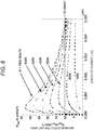
- Fig. 6 shows the results in a case where the effective heat transfer coefficient is 2,200 W/m 2 K, which matches a condition that the maximum power output is exactly 10 kW/m 2 . In this case, Fig. 5 shows that a maximum performance can be obtained where 0.5 ⁇ t ⁇ 0.7.
- Fig. 6 is a graph showing the calculation result of the maximum power output per unit area P max /A tot with respect to the length L of an element, using the effective heat transfer coefficient h* as a parameter.
- the graph shows that 10 kW/m 2 (equivalent to a conversion efficiency of 5%) can be achieved when the effective heat transfer coefficient is h* > 2,200 W/m 2 K.
- Fig. 7 is a diagram showing the results of Module-2 to Module-6.
- the experimental results are considered to show that changes with respect to the length L are different from the calculated results due to the temperature differences for technical reasons such as the forced water cooling. Further improvement in characteristics is expected by increasing the cross-sectional area of a heat discharging part (low temperature part).
Landscapes
- Chemical & Material Sciences (AREA)
- Inorganic Chemistry (AREA)
- Cooling Or The Like Of Semiconductors Or Solid State Devices (AREA)
- Silicon Compounds (AREA)
- Compositions Of Oxide Ceramics (AREA)
- Hybrid Cells (AREA)
Abstract
Description
- The present disclosure relates to a thermoelectric conversion module.
- The NEDO and TherMAT National Project has developed a thermoelectric conversion module for cogeneration that can improve power efficiency by 5% (for example, output of 10 kW/m2 in the cogeneration of 35kW class) from exhaust heat (from 300°C to 600°C) of cogeneration. In the cogeneration, while 30% of total fuel energy is wasted as heat, there is a demand to increase electricity even by 1%. An improvement of about 3% in a gas engine installed in the cogeneration is possible by improving the engine, but further improvement requires other improvement technologies.
- In general, a thermoelectric conversion module is configured by combining a p-type thermoelectric conversion material and an n-type thermoelectric conversion material. Thus, in order to obtain high thermoelectric conversion characteristics in the thermoelectric conversion module, it is obviously desired to obtain a high performance index ZT for both p-type and n-type thermoelectric conversion materials. Furthermore, performance can be maximized by optimizing the structure in accordance with element characteristics peculiar to the materials used.
- In this regard, for example, in
Patent Literature 1, a cross-sectional area ratio of the p-type element and the n-type element for maximizing the characteristics is specified as p-type: n-type = t: 1 - t, where 0.42 ≤ t ≤ 0.6 (see paragraph [0059] of Patent Literature 1). This is an optimum structure for thermoelectric elements based on an Fe-Ti-Si ternary system. - Further, for example, in
Patent Literature 2, although a material system of the thermoelectric element is not shown, the cross-sectional area ratio t is defined as 0.6 ≤ t ≤ 0.74. -
- Patent Literature 1:
JP 2015-122476 A - Patent Literature 2:
JP H11-274577 A - In a n-type module that combines a p-type element and an n-type element of ZT = 1 class, a power generation output changes depending on a module structure (element area and element thickness) and a heat source surface area which is a factor of a heat transfer capacity of the heat exchange part.
- However, in the conventional art represented by
Patent Literatures - In view of such circumstances, the present disclosure provides a thermoelectric conversion module that further improves power efficiency from exhaust heat of cogeneration.
- In order to solve the above problem, the present disclosure proposes, for example, a thermoelectric conversion module configured in multiple pairs, the thermoelectric conversion module including a p-type thermoelectric conversion material and an n-type thermoelectric conversion material, each of which is a silicide material based on a binary system, and heat supply units disposed on an upper surface and a lower surface in a thickness direction of the thermoelectric conversion module, configured to impart a temperature difference to the thermoelectric conversion module, and configured to supply heat source supplying heat for power generation by Seebeck effect of the p-type and n-type thermoelectric conversion materials and cooling source discharging heat, the p-type and n-type thermoelectric conversion materials being characterized by having a cross-sectional area ratio t satisfying:
- the p-type thermoelectric conversion material : the n-type thermoelectric conversion material = t: 1 - t,
- where 0.5 < t < 0.7, and a length L of a thermoelectric element satisfying L ≤ 5 mm.
- More features of the present disclosure will be apparent from the description of the present specification and the accompanying drawings. The aspects of the present disclosure are achieved and implemented by the elements, combinations of various elements, the following detailed description, and the aspects of the appended claims.
- The descriptions herein are merely exemplary, and are not intended to limit the scope of the claims or application of the present disclosure in any sense.
- The technology of the present disclosure can achieve a thermoelectric conversion module having a maximum power output exceeding 10 kW/m2 (equivalent to a conversion efficiency of 5%).
-
-
Fig. 1 is a diagram showing a configuration example of a single-pairthermoelectric conversion module 100. -
Fig. 2 is a diagram showing a configuration example of an electrical equivalent circuit of the single-pairthermoelectric conversion module 100. -
Fig. 3 is a diagram schematically showing a state of cross-sectional areas Ap and An. -
Fig. 4 is a diagram showing a state of cross-sectional areas in a multiple-pair module. -
Fig. 5 is a graph showing calculation results of a maximum power output per unit area Pmax/Atot with respect to a cross-sectional area ratio t. -
Fig. 6 is a graph showing the calculation results of the maximum power output per unit area Pmax/Atot with respect to a length L of an element, using an effective heat transfer coefficient h* as a parameter. The maximum power output per unit area for a length L of an element is plotted. The effective heat transfer coefficient is used as a parameter. In water cooling (forced convection), the heat transfer coefficient is h = 3,000 to 7,000 (W/m2K). -
Fig. 7 is a graph showing results of the maximum power output (Module-2 to Module-6) per unit area with respect to the length L of an element. The experimental results are shown in addition to the calculation results inFig. 6 . - The embodiment of the present disclosure is based on our binary silicide material (which is distinctively different from
Patent Literatures 1 and 2). Further, in the present embodiment, the structure is optimized in consideration of heat transfer regarding an outlet of a heat flow (which is different from Patent Literature 1). - In the present embodiment, the cross-sectional area ratio of the p-type thermoelectric conversion element and the n-type thermoelectric conversion element manufactured from a silicide material based on the binary system configuring the thermoelectric conversion module is optimized and the cross-sectional area of the electrodes at the outlet of the heat flow is optimized, thereby achieving a maximum power output (the power output of the thermoelectric conversion module using a silicide material based on the binary system is maximized). Hereinafter, examples according to the present embodiment will be described. In the examples, the description is given in sufficient detail for those skilled in the art to implement the technology of the present disclosure. However, other implementations and forms are also possible, and it is to be understood that a configuration or structure can be changed and various elements can be replaced without departing from the scope and spirit of the technical idea of the present disclosure. Therefore, the following description is not to be construed solely by the examples.
-
Fig. 1 is a diagram showing a configuration example of a single-pairthermoelectric conversion module 100.Fig. 2 is a diagram showing a configuration example of an electrical equivalent circuit of the single-pairthermoelectric conversion module 100. - Performance of the single-pair
thermoelectric conversion module 100 is derived from the electrical equivalent circuit shown inFig. 2 . Using the symbols inFig. 2 , Equation (1) is established for voltage.
[Math. 1]
- From equation (1), output Pout can be obtained as in Equation (2).
[Math. 2]
- The maximum power output Pmax of the thermoelectric conversion module is represented as in Equation (3).
[Math. 3]
In the case of R = rp + rn :
- Here, an internal resistances rp and rn can be obtained from Equation (4).
[Math. 4]
- Here, ρp and ρn are electrical resistivities in a length direction of the p-type and n-type thermoelectric conversion elements, respectively. Furthermore, generated voltages Vp and Vn can be obtained from a temperature integration of Seebeck coefficients (Sp and Sn) as in Equation (5).
[Math. 5]
- A temperature difference is smaller than an environmental temperature difference ΔT = TH-TC. This is because a thermal resistance is generated due to the heat transfer coefficient at an interface and thermal conductivity of the thermoelectric conversion element. As a result, the temperature difference generated at both ends of the element is represented as in Equation (6).
[Math. 6]
- Here, hp is the heat transfer coefficient at the interface between a high temperature electrode and the p-type thermoelectric conversion element, hp* is the effective heat transfer coefficient of a low temperature electrode, and hn and hn* are defined similarly. The effective heat transfer coefficient is defined as in Equation (7).
[Math. 7]
- Here, d is a thickness of the electrode and κ is the thermal conductivity of the electrode. Considering that the electrodes are thin and have high thermal conductivity and that the heat transfer coefficient is smaller at a water-cooling interface than at an element interface, Equation (7) can be approximately represented by the following Equation (8).
[Math. 8]
- Here, h' is the heat transfer coefficient of water cooling, Ap and An are the cross-sectional areas of the element, and Ap' and An' are surface areas of a water cooling part. According to the experimental data, temperature characteristics can be approximated linearly. From Equation (9) using the symbol <> indicating an average, the internal resistance and the generated voltage are represented as in Equation (10).
[Math. 9]
[Math. 10]
- Using Equations (9) and (10), the maximum power output Pmax of power generation is represented as in Equation (11), and the maximum power output per unit area is represented as in Equation (12).
[Math. 11]
[Math. 12]
- Here, α is a filling factor and is defined as in Equation (13).
[Math. 13]
- Here, an area A is represented as in Equation (14), and each Ap and An can be represented as in Equation (15) by using the cross-sectional area ratio t.
[Math. 14]
[Math. 15]
-
Fig. 3 is a diagram schematically showing a state of the cross-sectional areas Ap and An. InFig. 3 , a shape of the cross-sectional area is represented by a square; however, according to a theoretical formula, the result is irrelevant to the shape of the cross-sectional area and a circular, elliptical, or polygonal shape is also possible. For relaxing distortion, a circular shape is considered to be preferable. -
Fig. 4 is a diagram showing a state of cross-sectional areas in a multiple-pair module. In the multiple-pair module, as shown inFig. 4 , the filling factor α is obtained by (a sum of the cross-sectional areas of the p-type element and the n-type element) ÷ (a total bottom area of the module). Using the above, g(t) and v(L) are defined as in Equations (16) and (17), respectively.
[Math. 16]
[Math. 17]
- Here, fp (L) and fn (L) are defined by Equation (18).
[Math. 18]
- In order to maximize the power generation output per unit area Pmax/Atot, it is only necessary to minimize (t) and maximize v(L). First, g(t) is minimized in a state as shown in Equation (19).
[Math. 19]
- This means that the cross-sectional area ratio is determined only from the electrical resistivity as shown in Equation (20).
[Math. 20]
- Then, a minimum value of g(t) is represented as in Equation (21).
[Math. 21]
- Next, for maximizing v(L), a numerical calculation was performed to avoid a complicated equation.
- Thermoelectric performance of the silicide material based on the binary system (p-type thermoelectric element MnSi1.7 and n-type thermoelectric element Mg2Si) was calculated. Assuming that a high temperature part is at 500°C and a low temperature part is at 25°C, the following physical property values were used.
- Sp = 120 to 200 µV/K, kp = 2 to 2 W/Km, ρp = 12 to 20 µΩm, Sn = -100 to -220 µV/K, kn = 6.5 to 4 W/Km, and ρn = 5 to 12 µΩm.
-
Fig. 5 is a graph showing the calculation results of the maximum power output per unit area Pmax/Atot with respect to the cross-sectional area ratio t.Fig. 5 shows that the maximum output per unit area Pmax/Atot is the largest at around t = 0.6. The value at t = 0.6 is determined only by the electrical resistivity. Note thatFig. 6 shows the results in a case where the effective heat transfer coefficient is 2,200 W/m2K, which matches a condition that the maximum power output is exactly 10 kW/m2. In this case,Fig. 5 shows that a maximum performance can be obtained where 0.5 < t <0.7. -
Fig. 6 is a graph showing the calculation result of the maximum power output per unit area Pmax/Atot with respect to the length L of an element, using the effective heat transfer coefficient h* as a parameter. The graph shows that 10 kW/m2 (equivalent to a conversion efficiency of 5%) can be achieved when the effective heat transfer coefficient is h* > 2,200 W/m2K. The Microelectronics Package Handbook (p.138, Nikkei Business Publications, Inc.) describes that the heat transfer coefficient of forced water cooling is represented as h'= 3,000 to 7,000 W/m2K. This indicates that even when h' = 3,000 W/m2K, where the heat transfer coefficient is worst, the maximum power output of 10 kW/m2 can be achieved if Equation (22) is satisfied for the cross-sectional area ratio.
[Math. 22]
- Experiments were conducted on a single-pair module and a nine-pair module actually manufactured, and the following results were obtained for the single-pair module.
[Table 1] Module name Length of Element (mm) Cross-sectional area of p-type element (mm2) Cross-sectional area of n-type element (mm2) Maximum power output (kW/m2) Module-1 3.5 16 16 10.8 Module-2 3.5 16 11.56 11.0 Module-3 3 16 11.56 11. 6 Module-4 2 16 11.56 14.3 Module-5 1 16 11.56 13.3 Module-6 0.5 16 11.56 3.5 - A difference between Module-1 and Module-2 is the cross-sectional area ratio, which corresponds to t = 0.5 for Module-1 and t = 0.6 for Module-2. As predicted by the calculation of cross-sectional area ratio optimization, the output was slightly higher at t = 0.6 as an asymmetric area ratio.
-
Fig. 7 is a diagram showing the results of Module-2 to Module-6. InFig. 7 , the results are plotted as white circles. This indicates that the effective heat transfer coefficient is within a range where h* = 3,000 W/m2K to 4,000 W/m2K, which is consistent with the calculation results. The experimental results are considered to show that changes with respect to the length L are different from the calculated results due to the temperature differences for technical reasons such as the forced water cooling. Further improvement in characteristics is expected by increasing the cross-sectional area of a heat discharging part (low temperature part). -
- 100 single-pair thermoelectric conversion module
- 101 high temperature electrode
- 102 p-type thermoelectric conversion element
- 103 n-type thermoelectric conversion element
- 104 low temperature electrode
- 105 low temperature electrode
- 106 water flow
- TH heat source supplying heat (high temperature)
- TC cooling source exhausting heat (low temperature)
- 300 total bottom area Atot of single-pair module
- 301 cross-sectional area Ap of p-type thermoelectric conversion element
- 302 cross-sectional area An of n-type thermoelectric conversion element
- 400 total bottom area Atot of 12-pair module
- 401 cross-sectional area Ap of p-type thermoelectric conversion element (sum of areas of 12 pairs is 12Ap)
- 402 cross-sectional area An of n-type thermoelectric conversion element (sum of areas of 12 pairs is 12An)
- 403 output (positive electrode)
- 404 output (negative electrode)
Claims (3)
- A thermoelectric conversion module configured in multiple pairs, the thermoelectric conversion module comprising:a p-type thermoelectric conversion material and an n-type thermoelectric conversion material, each of which is a silicide material based on a binary system; andheat supply units disposed on an upper surface and a lower surface in a thickness direction of the thermoelectric conversion module, configured to impart a temperature difference to the thermoelectric conversion module, and configured to supply heat source supplying heat for power generation by Seebeck effect of the p-type and n-type thermoelectric conversion materials and cooling source discharging heat,the p-type and n-type thermoelectric conversion materials being characterized by having a cross-sectional area ratio t satisfying:the p-type thermoelectric conversion material : the n-type thermoelectric conversion material = t: 1 - t,where 0.5 < t < 0.7, and a length L of a thermoelectric element satisfying L ≤ 5 mm.
- The thermoelectric conversion module according to claim 1, characterized in that when cross-sectional areas where electrodes for discharging the heat from the p-type thermoelectric conversion material having a cross-sectional area Ap and the n-type thermoelectric conversion material having a cross-sectional area An are in contact with the cooling source are Ap' and An', respectively, the thermoelectric conversion module has an area ratio of Ap'/Ap ≥ 0.73 and An'/An ≥ 0.73.
- The thermoelectric conversion module according to claim 1, characterized in that the p-type thermoelectric conversion material has the cross-sectional area t = 0.6.
Applications Claiming Priority (1)
| Application Number | Priority Date | Filing Date | Title |
|---|---|---|---|
| JP2020010771A JP7518623B2 (en) | 2020-01-27 | 2020-01-27 | Thermoelectric conversion module |
Publications (3)
| Publication Number | Publication Date |
|---|---|
| EP3855518A2 true EP3855518A2 (en) | 2021-07-28 |
| EP3855518A3 EP3855518A3 (en) | 2021-08-18 |
| EP3855518B1 EP3855518B1 (en) | 2025-06-11 |
Family
ID=74045404
Family Applications (1)
| Application Number | Title | Priority Date | Filing Date |
|---|---|---|---|
| EP20217979.2A Active EP3855518B1 (en) | 2020-01-27 | 2020-12-31 | Thermoelectric conversion module |
Country Status (2)
| Country | Link |
|---|---|
| EP (1) | EP3855518B1 (en) |
| JP (1) | JP7518623B2 (en) |
Citations (1)
| Publication number | Priority date | Publication date | Assignee | Title |
|---|---|---|---|---|
| JP2015122476A (en) | 2013-11-19 | 2015-07-02 | 日立金属株式会社 | Thermoelectric conversion material, and thermoelectric conversion module arranged by use thereof |
Family Cites Families (8)
| Publication number | Priority date | Publication date | Assignee | Title |
|---|---|---|---|---|
| US6700053B2 (en) * | 2000-07-03 | 2004-03-02 | Komatsu Ltd. | Thermoelectric module |
| JP2007095897A (en) | 2005-09-28 | 2007-04-12 | Toshiba Corp | Semiconductor device and manufacturing method thereof |
| WO2008111218A1 (en) | 2007-03-15 | 2008-09-18 | Ibiden Co., Ltd. | Thermoelectric converter |
| WO2008111220A1 (en) * | 2007-03-15 | 2008-09-18 | Ibiden Co., Ltd. | Process for manufacturing thermoelectric converter |
| WO2013047474A1 (en) | 2011-09-26 | 2013-04-04 | 学校法人東京理科大学 | Sintered body, sintered body for thermoelectric conversion element, thermoelectric conversion element, and thermoelectric conversion module |
| WO2013175571A1 (en) * | 2012-05-22 | 2013-11-28 | 株式会社日立製作所 | Thermoelectric conversion module |
| WO2017057259A1 (en) * | 2015-09-28 | 2017-04-06 | 三菱マテリアル株式会社 | Thermoelectric conversion module and thermoelectric conversion device |
| JP6957916B2 (en) | 2017-03-21 | 2021-11-02 | 三菱マテリアル株式会社 | Thermoelectric conversion module |
-
2020
- 2020-01-27 JP JP2020010771A patent/JP7518623B2/en active Active
- 2020-12-31 EP EP20217979.2A patent/EP3855518B1/en active Active
Patent Citations (1)
| Publication number | Priority date | Publication date | Assignee | Title |
|---|---|---|---|---|
| JP2015122476A (en) | 2013-11-19 | 2015-07-02 | 日立金属株式会社 | Thermoelectric conversion material, and thermoelectric conversion module arranged by use thereof |
Also Published As
| Publication number | Publication date |
|---|---|
| JP7518623B2 (en) | 2024-07-18 |
| EP3855518B1 (en) | 2025-06-11 |
| JP2021118263A (en) | 2021-08-10 |
| EP3855518A3 (en) | 2021-08-18 |
Similar Documents
| Publication | Publication Date | Title |
|---|---|---|
| US20090038667A1 (en) | Thermoelectric conversion module and heat exchanger and thermoelectric power generator using it | |
| RU2008148931A (en) | LOW SIZED THERMOELECTRICS MADE BY ETCHING SEMICONDUCTOR PLATES | |
| EP1635405A2 (en) | Thin film thermoelectric module | |
| CN102456829A (en) | Thermoelectric generator including a thermoelectric module having a meandering p-n system | |
| WO2007081483A2 (en) | Thermoelectric tunnelling device | |
| KR20130071759A (en) | Cooling thermoelectric moudule and method of manufacturing method of the same | |
| KR102212290B1 (en) | Reduced contact resistance and improved lifetime of solar cells | |
| US11251315B2 (en) | Solar cells with improved lifetime, passivation and/or efficiency | |
| EP3855518B1 (en) | Thermoelectric conversion module | |
| US20220069189A1 (en) | Thermoelectric power generator | |
| CA2529224C (en) | Co-generation of electricity by the seebeck effect within a fuel cell | |
| US20140182647A1 (en) | Process For Manufacturing A Thermoelectric Device, Especially Intended To Generate An Electrical Current In An Automotive Vehicle, And Thermoelectric Device Obtained By Such A Process | |
| KR20180128186A (en) | Thermoelectric module | |
| CN119451140A (en) | MPS diode and manufacturing method thereof | |
| EP3435431B1 (en) | Thermoelectric conversion module | |
| CN111613687A (en) | a solar cell | |
| CN114701351B (en) | Radiator water tank capable of generating electricity and automobile | |
| US20230075288A1 (en) | Power generation apparatus | |
| CN119855170B (en) | A trench junction barrier Schottky diode and a manufacturing method thereof | |
| KR20210090998A (en) | Heat conversion device | |
| CN214898471U (en) | Photovoltaic module | |
| CN222547950U (en) | Cooling components and battery components | |
| CN214848654U (en) | Photovoltaic module | |
| US20250089569A1 (en) | Thermocouple Power Generation Unit, Module, and Device | |
| KR101344527B1 (en) | A Heat Exchanger using Thermoelectric Modules |
Legal Events
| Date | Code | Title | Description |
|---|---|---|---|
| PUAI | Public reference made under article 153(3) epc to a published international application that has entered the european phase |
Free format text: ORIGINAL CODE: 0009012 |
|
| STAA | Information on the status of an ep patent application or granted ep patent |
Free format text: STATUS: REQUEST FOR EXAMINATION WAS MADE |
|
| PUAL | Search report despatched |
Free format text: ORIGINAL CODE: 0009013 |
|
| 17P | Request for examination filed |
Effective date: 20201231 |
|
| AK | Designated contracting states |
Kind code of ref document: A2 Designated state(s): AL AT BE BG CH CY CZ DE DK EE ES FI FR GB GR HR HU IE IS IT LI LT LU LV MC MK MT NL NO PL PT RO RS SE SI SK SM TR |
|
| AK | Designated contracting states |
Kind code of ref document: A3 Designated state(s): AL AT BE BG CH CY CZ DE DK EE ES FI FR GB GR HR HU IE IS IT LI LT LU LV MC MK MT NL NO PL PT RO RS SE SI SK SM TR |
|
| RIC1 | Information provided on ipc code assigned before grant |
Ipc: H01L 35/32 20060101AFI20210712BHEP Ipc: H01L 35/22 20060101ALI20210712BHEP |
|
| STAA | Information on the status of an ep patent application or granted ep patent |
Free format text: STATUS: EXAMINATION IS IN PROGRESS |
|
| 17Q | First examination report despatched |
Effective date: 20240327 |
|
| REG | Reference to a national code |
Ref country code: DE Ref legal event code: R079 Free format text: PREVIOUS MAIN CLASS: H01L0035320000 Ipc: H10N0010170000 Ref country code: DE Ref legal event code: R079 Ref document number: 602020052574 Country of ref document: DE Free format text: PREVIOUS MAIN CLASS: H01L0035320000 Ipc: H10N0010170000 |
|
| RIC1 | Information provided on ipc code assigned before grant |
Ipc: H10N 10/851 20230101ALI20241129BHEP Ipc: H10N 10/17 20230101AFI20241129BHEP |
|
| GRAP | Despatch of communication of intention to grant a patent |
Free format text: ORIGINAL CODE: EPIDOSNIGR1 |
|
| STAA | Information on the status of an ep patent application or granted ep patent |
Free format text: STATUS: GRANT OF PATENT IS INTENDED |
|
| INTG | Intention to grant announced |
Effective date: 20250206 |
|
| RIN1 | Information on inventor provided before grant (corrected) |
Inventor name: HAYAKAWA, JUN Inventor name: FUKATANI, NAOTO Inventor name: OKAMOTO, MASAKUNI |
|
| GRAS | Grant fee paid |
Free format text: ORIGINAL CODE: EPIDOSNIGR3 |
|
| GRAA | (expected) grant |
Free format text: ORIGINAL CODE: 0009210 |
|
| STAA | Information on the status of an ep patent application or granted ep patent |
Free format text: STATUS: THE PATENT HAS BEEN GRANTED |
|
| AK | Designated contracting states |
Kind code of ref document: B1 Designated state(s): AL AT BE BG CH CY CZ DE DK EE ES FI FR GB GR HR HU IE IS IT LI LT LU LV MC MK MT NL NO PL PT RO RS SE SI SK SM TR |
|
| REG | Reference to a national code |
Ref country code: GB Ref legal event code: FG4D |
|
| REG | Reference to a national code |
Ref country code: CH Ref legal event code: EP |
|
| REG | Reference to a national code |
Ref country code: IE Ref legal event code: FG4D |
|
| REG | Reference to a national code |
Ref country code: DE Ref legal event code: R096 Ref document number: 602020052574 Country of ref document: DE |
|
| PG25 | Lapsed in a contracting state [announced via postgrant information from national office to epo] |
Ref country code: FI Free format text: LAPSE BECAUSE OF FAILURE TO SUBMIT A TRANSLATION OF THE DESCRIPTION OR TO PAY THE FEE WITHIN THE PRESCRIBED TIME-LIMIT Effective date: 20250611 Ref country code: ES Free format text: LAPSE BECAUSE OF FAILURE TO SUBMIT A TRANSLATION OF THE DESCRIPTION OR TO PAY THE FEE WITHIN THE PRESCRIBED TIME-LIMIT Effective date: 20250611 |
|
| REG | Reference to a national code |
Ref country code: LT Ref legal event code: MG9D |
|
| PG25 | Lapsed in a contracting state [announced via postgrant information from national office to epo] |
Ref country code: GR Free format text: LAPSE BECAUSE OF FAILURE TO SUBMIT A TRANSLATION OF THE DESCRIPTION OR TO PAY THE FEE WITHIN THE PRESCRIBED TIME-LIMIT Effective date: 20250912 Ref country code: NO Free format text: LAPSE BECAUSE OF FAILURE TO SUBMIT A TRANSLATION OF THE DESCRIPTION OR TO PAY THE FEE WITHIN THE PRESCRIBED TIME-LIMIT Effective date: 20250911 |
|
| REG | Reference to a national code |
Ref country code: NL Ref legal event code: MP Effective date: 20250611 |
|
| PG25 | Lapsed in a contracting state [announced via postgrant information from national office to epo] |
Ref country code: BG Free format text: LAPSE BECAUSE OF FAILURE TO SUBMIT A TRANSLATION OF THE DESCRIPTION OR TO PAY THE FEE WITHIN THE PRESCRIBED TIME-LIMIT Effective date: 20250611 |
|
| PG25 | Lapsed in a contracting state [announced via postgrant information from national office to epo] |
Ref country code: HR Free format text: LAPSE BECAUSE OF FAILURE TO SUBMIT A TRANSLATION OF THE DESCRIPTION OR TO PAY THE FEE WITHIN THE PRESCRIBED TIME-LIMIT Effective date: 20250611 |
|
| PG25 | Lapsed in a contracting state [announced via postgrant information from national office to epo] |
Ref country code: RS Free format text: LAPSE BECAUSE OF FAILURE TO SUBMIT A TRANSLATION OF THE DESCRIPTION OR TO PAY THE FEE WITHIN THE PRESCRIBED TIME-LIMIT Effective date: 20250911 |
|
| PG25 | Lapsed in a contracting state [announced via postgrant information from national office to epo] |
Ref country code: LV Free format text: LAPSE BECAUSE OF FAILURE TO SUBMIT A TRANSLATION OF THE DESCRIPTION OR TO PAY THE FEE WITHIN THE PRESCRIBED TIME-LIMIT Effective date: 20250611 |
|
| PG25 | Lapsed in a contracting state [announced via postgrant information from national office to epo] |
Ref country code: NL Free format text: LAPSE BECAUSE OF FAILURE TO SUBMIT A TRANSLATION OF THE DESCRIPTION OR TO PAY THE FEE WITHIN THE PRESCRIBED TIME-LIMIT Effective date: 20250611 |
|
| PG25 | Lapsed in a contracting state [announced via postgrant information from national office to epo] |
Ref country code: PT Free format text: LAPSE BECAUSE OF FAILURE TO SUBMIT A TRANSLATION OF THE DESCRIPTION OR TO PAY THE FEE WITHIN THE PRESCRIBED TIME-LIMIT Effective date: 20251013 |
|
| REG | Reference to a national code |
Ref country code: AT Ref legal event code: MK05 Ref document number: 1803310 Country of ref document: AT Kind code of ref document: T Effective date: 20250611 |
|
| PG25 | Lapsed in a contracting state [announced via postgrant information from national office to epo] |
Ref country code: IS Free format text: LAPSE BECAUSE OF FAILURE TO SUBMIT A TRANSLATION OF THE DESCRIPTION OR TO PAY THE FEE WITHIN THE PRESCRIBED TIME-LIMIT Effective date: 20251011 |
|
| PG25 | Lapsed in a contracting state [announced via postgrant information from national office to epo] |
Ref country code: AT Free format text: LAPSE BECAUSE OF FAILURE TO SUBMIT A TRANSLATION OF THE DESCRIPTION OR TO PAY THE FEE WITHIN THE PRESCRIBED TIME-LIMIT Effective date: 20250611 Ref country code: SM Free format text: LAPSE BECAUSE OF FAILURE TO SUBMIT A TRANSLATION OF THE DESCRIPTION OR TO PAY THE FEE WITHIN THE PRESCRIBED TIME-LIMIT Effective date: 20250611 |
|
| PG25 | Lapsed in a contracting state [announced via postgrant information from national office to epo] |
Ref country code: CZ Free format text: LAPSE BECAUSE OF FAILURE TO SUBMIT A TRANSLATION OF THE DESCRIPTION OR TO PAY THE FEE WITHIN THE PRESCRIBED TIME-LIMIT Effective date: 20250611 |
|
| PG25 | Lapsed in a contracting state [announced via postgrant information from national office to epo] |
Ref country code: PL Free format text: LAPSE BECAUSE OF FAILURE TO SUBMIT A TRANSLATION OF THE DESCRIPTION OR TO PAY THE FEE WITHIN THE PRESCRIBED TIME-LIMIT Effective date: 20250611 |
|
| PG25 | Lapsed in a contracting state [announced via postgrant information from national office to epo] |
Ref country code: EE Free format text: LAPSE BECAUSE OF FAILURE TO SUBMIT A TRANSLATION OF THE DESCRIPTION OR TO PAY THE FEE WITHIN THE PRESCRIBED TIME-LIMIT Effective date: 20250611 |
|
| PG25 | Lapsed in a contracting state [announced via postgrant information from national office to epo] |
Ref country code: SK Free format text: LAPSE BECAUSE OF FAILURE TO SUBMIT A TRANSLATION OF THE DESCRIPTION OR TO PAY THE FEE WITHIN THE PRESCRIBED TIME-LIMIT Effective date: 20250611 Ref country code: RO Free format text: LAPSE BECAUSE OF FAILURE TO SUBMIT A TRANSLATION OF THE DESCRIPTION OR TO PAY THE FEE WITHIN THE PRESCRIBED TIME-LIMIT Effective date: 20250611 |
|
| REG | Reference to a national code |
Ref country code: DE Ref legal event code: R097 Ref document number: 602020052574 Country of ref document: DE |
|
| PG25 | Lapsed in a contracting state [announced via postgrant information from national office to epo] |
Ref country code: DK Free format text: LAPSE BECAUSE OF FAILURE TO SUBMIT A TRANSLATION OF THE DESCRIPTION OR TO PAY THE FEE WITHIN THE PRESCRIBED TIME-LIMIT Effective date: 20250611 |
|
| PGFP | Annual fee paid to national office [announced via postgrant information from national office to epo] |
Ref country code: DE Payment date: 20251219 Year of fee payment: 6 |
|
| PG25 | Lapsed in a contracting state [announced via postgrant information from national office to epo] |
Ref country code: IT Free format text: LAPSE BECAUSE OF FAILURE TO SUBMIT A TRANSLATION OF THE DESCRIPTION OR TO PAY THE FEE WITHIN THE PRESCRIBED TIME-LIMIT Effective date: 20250611 |
|
| PLBE | No opposition filed within time limit |
Free format text: ORIGINAL CODE: 0009261 |
|
| STAA | Information on the status of an ep patent application or granted ep patent |
Free format text: STATUS: NO OPPOSITION FILED WITHIN TIME LIMIT |
|
| REG | Reference to a national code |
Ref country code: CH Ref legal event code: L10 Free format text: ST27 STATUS EVENT CODE: U-0-0-L10-L00 (AS PROVIDED BY THE NATIONAL OFFICE) Effective date: 20260423 |