EP3855459A1 - Sintered magnet manufacturing method and sintered magnet - Google Patents
Sintered magnet manufacturing method and sintered magnet Download PDFInfo
- Publication number
- EP3855459A1 EP3855459A1 EP20867972.0A EP20867972A EP3855459A1 EP 3855459 A1 EP3855459 A1 EP 3855459A1 EP 20867972 A EP20867972 A EP 20867972A EP 3855459 A1 EP3855459 A1 EP 3855459A1
- Authority
- EP
- European Patent Office
- Prior art keywords
- powder
- sintered magnet
- sintered
- producing
- sintering
- Prior art date
- Legal status (The legal status is an assumption and is not a legal conclusion. Google has not performed a legal analysis and makes no representation as to the accuracy of the status listed.)
- Granted
Links
Images



Classifications
-
- H—ELECTRICITY
- H01—ELECTRIC ELEMENTS
- H01F—MAGNETS; INDUCTANCES; TRANSFORMERS; SELECTION OF MATERIALS FOR THEIR MAGNETIC PROPERTIES
- H01F41/00—Apparatus or processes specially adapted for manufacturing or assembling magnets, inductances or transformers; Apparatus or processes specially adapted for manufacturing materials characterised by their magnetic properties
- H01F41/02—Apparatus or processes specially adapted for manufacturing or assembling magnets, inductances or transformers; Apparatus or processes specially adapted for manufacturing materials characterised by their magnetic properties for manufacturing cores, coils, or magnets
-
- H—ELECTRICITY
- H01—ELECTRIC ELEMENTS
- H01F—MAGNETS; INDUCTANCES; TRANSFORMERS; SELECTION OF MATERIALS FOR THEIR MAGNETIC PROPERTIES
- H01F41/00—Apparatus or processes specially adapted for manufacturing or assembling magnets, inductances or transformers; Apparatus or processes specially adapted for manufacturing materials characterised by their magnetic properties
- H01F41/02—Apparatus or processes specially adapted for manufacturing or assembling magnets, inductances or transformers; Apparatus or processes specially adapted for manufacturing materials characterised by their magnetic properties for manufacturing cores, coils, or magnets
- H01F41/0253—Apparatus or processes specially adapted for manufacturing or assembling magnets, inductances or transformers; Apparatus or processes specially adapted for manufacturing materials characterised by their magnetic properties for manufacturing cores, coils, or magnets for manufacturing permanent magnets
-
- B—PERFORMING OPERATIONS; TRANSPORTING
- B22—CASTING; POWDER METALLURGY
- B22F—WORKING METALLIC POWDER; MANUFACTURE OF ARTICLES FROM METALLIC POWDER; MAKING METALLIC POWDER; APPARATUS OR DEVICES SPECIALLY ADAPTED FOR METALLIC POWDER
- B22F1/00—Metallic powder; Treatment of metallic powder, e.g. to facilitate working or to improve properties
- B22F1/14—Treatment of metallic powder
- B22F1/148—Agglomerating
-
- B—PERFORMING OPERATIONS; TRANSPORTING
- B22—CASTING; POWDER METALLURGY
- B22F—WORKING METALLIC POWDER; MANUFACTURE OF ARTICLES FROM METALLIC POWDER; MAKING METALLIC POWDER; APPARATUS OR DEVICES SPECIALLY ADAPTED FOR METALLIC POWDER
- B22F3/00—Manufacture of workpieces or articles from metallic powder characterised by the manner of compacting or sintering; Apparatus specially adapted therefor ; Presses and furnaces
- B22F3/10—Sintering only
-
- B—PERFORMING OPERATIONS; TRANSPORTING
- B22—CASTING; POWDER METALLURGY
- B22F—WORKING METALLIC POWDER; MANUFACTURE OF ARTICLES FROM METALLIC POWDER; MAKING METALLIC POWDER; APPARATUS OR DEVICES SPECIALLY ADAPTED FOR METALLIC POWDER
- B22F3/00—Manufacture of workpieces or articles from metallic powder characterised by the manner of compacting or sintering; Apparatus specially adapted therefor ; Presses and furnaces
- B22F3/10—Sintering only
- B22F3/1003—Use of special medium during sintering, e.g. sintering aid
-
- B—PERFORMING OPERATIONS; TRANSPORTING
- B22—CASTING; POWDER METALLURGY
- B22F—WORKING METALLIC POWDER; MANUFACTURE OF ARTICLES FROM METALLIC POWDER; MAKING METALLIC POWDER; APPARATUS OR DEVICES SPECIALLY ADAPTED FOR METALLIC POWDER
- B22F3/00—Manufacture of workpieces or articles from metallic powder characterised by the manner of compacting or sintering; Apparatus specially adapted therefor ; Presses and furnaces
- B22F3/10—Sintering only
- B22F3/1035—Liquid phase sintering
-
- B—PERFORMING OPERATIONS; TRANSPORTING
- B22—CASTING; POWDER METALLURGY
- B22F—WORKING METALLIC POWDER; MANUFACTURE OF ARTICLES FROM METALLIC POWDER; MAKING METALLIC POWDER; APPARATUS OR DEVICES SPECIALLY ADAPTED FOR METALLIC POWDER
- B22F3/00—Manufacture of workpieces or articles from metallic powder characterised by the manner of compacting or sintering; Apparatus specially adapted therefor ; Presses and furnaces
- B22F3/24—After-treatment of workpieces or articles
-
- B—PERFORMING OPERATIONS; TRANSPORTING
- B22—CASTING; POWDER METALLURGY
- B22F—WORKING METALLIC POWDER; MANUFACTURE OF ARTICLES FROM METALLIC POWDER; MAKING METALLIC POWDER; APPARATUS OR DEVICES SPECIALLY ADAPTED FOR METALLIC POWDER
- B22F9/00—Making metallic powder or suspensions thereof
- B22F9/16—Making metallic powder or suspensions thereof using chemical processes
- B22F9/18—Making metallic powder or suspensions thereof using chemical processes with reduction of metal compounds
- B22F9/20—Making metallic powder or suspensions thereof using chemical processes with reduction of metal compounds starting from solid metal compounds
-
- C—CHEMISTRY; METALLURGY
- C22—METALLURGY; FERROUS OR NON-FERROUS ALLOYS; TREATMENT OF ALLOYS OR NON-FERROUS METALS
- C22C—ALLOYS
- C22C38/00—Ferrous alloys, e.g. steel alloys
- C22C38/002—Ferrous alloys, e.g. steel alloys containing In, Mg, or other elements not provided for in one single group C22C38/001 - C22C38/60
-
- C—CHEMISTRY; METALLURGY
- C22—METALLURGY; FERROUS OR NON-FERROUS ALLOYS; TREATMENT OF ALLOYS OR NON-FERROUS METALS
- C22C—ALLOYS
- C22C38/00—Ferrous alloys, e.g. steel alloys
- C22C38/005—Ferrous alloys, e.g. steel alloys containing rare earths, i.e. Sc, Y, Lanthanides
-
- C—CHEMISTRY; METALLURGY
- C22—METALLURGY; FERROUS OR NON-FERROUS ALLOYS; TREATMENT OF ALLOYS OR NON-FERROUS METALS
- C22C—ALLOYS
- C22C38/00—Ferrous alloys, e.g. steel alloys
- C22C38/06—Ferrous alloys, e.g. steel alloys containing aluminium
-
- C—CHEMISTRY; METALLURGY
- C22—METALLURGY; FERROUS OR NON-FERROUS ALLOYS; TREATMENT OF ALLOYS OR NON-FERROUS METALS
- C22C—ALLOYS
- C22C38/00—Ferrous alloys, e.g. steel alloys
- C22C38/16—Ferrous alloys, e.g. steel alloys containing copper
-
- H—ELECTRICITY
- H01—ELECTRIC ELEMENTS
- H01F—MAGNETS; INDUCTANCES; TRANSFORMERS; SELECTION OF MATERIALS FOR THEIR MAGNETIC PROPERTIES
- H01F1/00—Magnets or magnetic bodies characterised by the magnetic materials therefor; Selection of materials for their magnetic properties
- H01F1/01—Magnets or magnetic bodies characterised by the magnetic materials therefor; Selection of materials for their magnetic properties of inorganic materials
- H01F1/03—Magnets or magnetic bodies characterised by the magnetic materials therefor; Selection of materials for their magnetic properties of inorganic materials characterised by their coercivity
- H01F1/032—Magnets or magnetic bodies characterised by the magnetic materials therefor; Selection of materials for their magnetic properties of inorganic materials characterised by their coercivity of hard-magnetic materials
- H01F1/04—Magnets or magnetic bodies characterised by the magnetic materials therefor; Selection of materials for their magnetic properties of inorganic materials characterised by their coercivity of hard-magnetic materials metals or alloys
- H01F1/047—Alloys characterised by their composition
- H01F1/053—Alloys characterised by their composition containing rare earth metals
- H01F1/0536—Alloys characterised by their composition containing rare earth metals sintered
-
- H—ELECTRICITY
- H01—ELECTRIC ELEMENTS
- H01F—MAGNETS; INDUCTANCES; TRANSFORMERS; SELECTION OF MATERIALS FOR THEIR MAGNETIC PROPERTIES
- H01F1/00—Magnets or magnetic bodies characterised by the magnetic materials therefor; Selection of materials for their magnetic properties
- H01F1/01—Magnets or magnetic bodies characterised by the magnetic materials therefor; Selection of materials for their magnetic properties of inorganic materials
- H01F1/03—Magnets or magnetic bodies characterised by the magnetic materials therefor; Selection of materials for their magnetic properties of inorganic materials characterised by their coercivity
- H01F1/032—Magnets or magnetic bodies characterised by the magnetic materials therefor; Selection of materials for their magnetic properties of inorganic materials characterised by their coercivity of hard-magnetic materials
- H01F1/04—Magnets or magnetic bodies characterised by the magnetic materials therefor; Selection of materials for their magnetic properties of inorganic materials characterised by their coercivity of hard-magnetic materials metals or alloys
- H01F1/047—Alloys characterised by their composition
- H01F1/053—Alloys characterised by their composition containing rare earth metals
- H01F1/055—Alloys characterised by their composition containing rare earth metals and magnetic transition metals, e.g. SmCo5
- H01F1/057—Alloys characterised by their composition containing rare earth metals and magnetic transition metals, e.g. SmCo5 and IIIa elements, e.g. Nd2Fe14B
- H01F1/0571—Alloys characterised by their composition containing rare earth metals and magnetic transition metals, e.g. SmCo5 and IIIa elements, e.g. Nd2Fe14B in the form of particles, e.g. rapid quenched powders or ribbon flakes
- H01F1/0575—Alloys characterised by their composition containing rare earth metals and magnetic transition metals, e.g. SmCo5 and IIIa elements, e.g. Nd2Fe14B in the form of particles, e.g. rapid quenched powders or ribbon flakes pressed, sintered or bonded together
- H01F1/0577—Alloys characterised by their composition containing rare earth metals and magnetic transition metals, e.g. SmCo5 and IIIa elements, e.g. Nd2Fe14B in the form of particles, e.g. rapid quenched powders or ribbon flakes pressed, sintered or bonded together sintered
-
- H—ELECTRICITY
- H01—ELECTRIC ELEMENTS
- H01F—MAGNETS; INDUCTANCES; TRANSFORMERS; SELECTION OF MATERIALS FOR THEIR MAGNETIC PROPERTIES
- H01F41/00—Apparatus or processes specially adapted for manufacturing or assembling magnets, inductances or transformers; Apparatus or processes specially adapted for manufacturing materials characterised by their magnetic properties
- H01F41/02—Apparatus or processes specially adapted for manufacturing or assembling magnets, inductances or transformers; Apparatus or processes specially adapted for manufacturing materials characterised by their magnetic properties for manufacturing cores, coils, or magnets
- H01F41/0253—Apparatus or processes specially adapted for manufacturing or assembling magnets, inductances or transformers; Apparatus or processes specially adapted for manufacturing materials characterised by their magnetic properties for manufacturing cores, coils, or magnets for manufacturing permanent magnets
- H01F41/0266—Moulding; Pressing
-
- B—PERFORMING OPERATIONS; TRANSPORTING
- B22—CASTING; POWDER METALLURGY
- B22F—WORKING METALLIC POWDER; MANUFACTURE OF ARTICLES FROM METALLIC POWDER; MAKING METALLIC POWDER; APPARATUS OR DEVICES SPECIALLY ADAPTED FOR METALLIC POWDER
- B22F3/00—Manufacture of workpieces or articles from metallic powder characterised by the manner of compacting or sintering; Apparatus specially adapted therefor ; Presses and furnaces
- B22F3/24—After-treatment of workpieces or articles
- B22F2003/248—Thermal after-treatment
-
- B—PERFORMING OPERATIONS; TRANSPORTING
- B22—CASTING; POWDER METALLURGY
- B22F—WORKING METALLIC POWDER; MANUFACTURE OF ARTICLES FROM METALLIC POWDER; MAKING METALLIC POWDER; APPARATUS OR DEVICES SPECIALLY ADAPTED FOR METALLIC POWDER
- B22F2201/00—Treatment under specific atmosphere
- B22F2201/10—Inert gases
- B22F2201/11—Argon
-
- B—PERFORMING OPERATIONS; TRANSPORTING
- B22—CASTING; POWDER METALLURGY
- B22F—WORKING METALLIC POWDER; MANUFACTURE OF ARTICLES FROM METALLIC POWDER; MAKING METALLIC POWDER; APPARATUS OR DEVICES SPECIALLY ADAPTED FOR METALLIC POWDER
- B22F2301/00—Metallic composition of the powder or its coating
- B22F2301/35—Iron
- B22F2301/355—Rare Earth - Fe intermetallic alloys
-
- B—PERFORMING OPERATIONS; TRANSPORTING
- B22—CASTING; POWDER METALLURGY
- B22F—WORKING METALLIC POWDER; MANUFACTURE OF ARTICLES FROM METALLIC POWDER; MAKING METALLIC POWDER; APPARATUS OR DEVICES SPECIALLY ADAPTED FOR METALLIC POWDER
- B22F2998/00—Supplementary information concerning processes or compositions relating to powder metallurgy
- B22F2998/10—Processes characterised by the sequence of their steps
-
- B—PERFORMING OPERATIONS; TRANSPORTING
- B22—CASTING; POWDER METALLURGY
- B22F—WORKING METALLIC POWDER; MANUFACTURE OF ARTICLES FROM METALLIC POWDER; MAKING METALLIC POWDER; APPARATUS OR DEVICES SPECIALLY ADAPTED FOR METALLIC POWDER
- B22F2999/00—Aspects linked to processes or compositions used in powder metallurgy
-
- C—CHEMISTRY; METALLURGY
- C22—METALLURGY; FERROUS OR NON-FERROUS ALLOYS; TREATMENT OF ALLOYS OR NON-FERROUS METALS
- C22C—ALLOYS
- C22C2202/00—Physical properties
- C22C2202/02—Magnetic
Definitions
- the present disclosure relates to a method for producing a sintered magnet and a sintered magnet produced thereby. More specifically, it relates to a method for producing a sintered magnet that improves magnetic properties using a sintering agent, and a sintered magnet produced by this method.
- NdFeB-based magnets are permanent magnets having a composition of Nd 2 Fe 14 B which is a compound of neodymium (Nd), a rare earth element, and iron and boron (B), and have been used as general-purpose permanent magnets for 30 years since there were developed in 1983.
- the NdFeB-based magnets are used in various fields such as electronic information, automobile industry, medical equipment, energy, and transportation. In particular, in line with recent trends in weight reduction and miniaturization, they are used in products such as machine tools, electronic information devices, electronic products for home appliances, mobile phones, robot motors, wind power generators, small motors for automobiles, and driving motors.
- the strip/mold casting method is a process in which metals such as neodymium (Nd), iron (Fe), boron (B) are melted by heating to produce an ingot, crystal grain particles are coarsely pulverized and subjected to a miniaturization process to produce microparticles. These steps are repeated to obtain a magnet powder, which is subjected to a pressing and sintering process under a magnetic field to produce an anisotropic sintered magnet.
- Nd neodymium
- Fe iron
- B boron
- melt spinning method is a process in which metal elements are melted, then poured into a wheel rotating at a high speed, rapidly cooled, pulverized by a jet mill, then blended with a polymer to form a bonded magnet, or pressed to produce a magnet.
- NdFeB fine particles can be produced through a reduction-diffusion process in which Nd 2 O 3 , Fe, and B are mixed and reduced with Ca or the like.
- an oxide film may be formed in the process of removing a reducing agent such as Ca and a reduced by-product used at the time of reduction in this method. The oxide film makes it difficult to sinter the magnetic powder, and the high oxygen content promotes the decomposition of columnar magnetic particles, and the properties of the sintered magnet obtained by sintering the magnetic powder may be deteriorated.
- Embodiments of the present disclosure has been designed to solve the above-mentioned problems, and an object of the present disclosure is to provide a method for producing a sintered magnet that improves the properties of a sintered magnet by adjusting the phase distributed in the grain boundary during sintering of magnetic powder, and a sintered magnet produced by this method.
- a method for producing a sintered magnet according to an embodiment of the present disclosure includes the steps of: producing an R-Fe-B-based magnet powder by a reduction-diffusion method, adding a R-Al-Cu powder as a sintering agent to the R-Fe-B-based magnet powder to form a mixed powder, and sintering the mixed powder to form a sintered magnet, wherein the R-Al-Cu powder is an alloy of R, Al and Cu, and the R is Nd, Pr, Dy, Tb or Ce.
- the method for producing a sintered magnet may further include a step of forming a R-Al-Cu powder as the sintering agent, wherein the step of forming the R-Al-Cu powder may include the steps of: mixing RH 2 powder, Al powder, and Cu powder to form a sintered precursor, agglomerating the sintered precursor, raising the temperature of the agglomerated sintered precursor to form a metal alloy, and pulverizing the metal alloy to form the sintering agent.
- the method for producing a sintered magnet may further include the step of wrapping the sintered precursor in a metal foil when raising the temperature of the agglomerated sintered precursor.
- the step of forming the sintered precursor may further include a step of mixing a liquid Ga.
- the metal foil may be Mo or Ta.
- the temperature When wrapping the agglomerated sintered precursor in the metal foil and raising the temperature, the temperature may be raised in an argon gas atmosphere.
- the step of forming the metal alloy may further include the step of wrapping the agglomerated sintered precursor in the metal foil, raising the temperature up to 900 degrees Celsius to 1050 degrees Celsius, and then performing an additional heat treatment.
- the step of agglomerating the sintered precursor may use any one of hydraulic pressing, tapping, and cold isostatic pressing (CIP).
- the method for producing a sintered magnet may further include a step of adding NdH 2 powder to the R-Al-Cu powder as the sintering agent.
- a sintered magnet according to another embodiment of the present disclosure is produced by the above-mentioned production method.
- the powder of the metal alloy in order to prevent the properties of the sintered magnet from being deteriorated by the oxide film generated when producing the magnetic powder as in the prior art, can be used as a sintering agent, thereby preventing the deterioration of the properties of the sintered magnet properties while lowering the melting temperature
- a magnetic powder can be produced through a reduction-diffusion process using a low-cost rare earth oxide.
- An oxide film can be formed in the process of removing a reducing agent such as Ca and a reduced by-product used at the time of reduction by such a method.
- a reducing agent such as Ca
- a reduced by-product used at the time of reduction by such a method.
- Such an oxide film makes it difficult to sinter the magnetic powder and may impair the properties of the sintered magnet.
- the present embodiment uses the powder of the metal alloy as a sintering agent, thereby being able to prevent the deterioration of the properties of the sintered magnet while lowering the melting temperature.
- the cost when the melting temperature is lowered during production of a metal alloy used as a sintering agent, the cost can be reduced. Specifically, according to the present embodiment, since the sintering agent is produced below 1050 degrees Celsius by using RH 2 powder and respective metal powders, the economic efficiency can be improved at the process stage. Further, in the case of a metal material such as Ga that is liquid at room temperature, if arc melting is used, it is scattered during arc formation, which is technically difficult to make an alloy, whereas according to the present embodiment, it is possible to add an exact ratio.
- the metal alloy as a sintering agent corresponds to 1) a case in which 1) each metal powder corresponding to each element constituting the alloy is included as a sintering agent, or 2) a case in which a material corresponding to each element constituting the alloy is prepared as a precursor before sintering and metal alloy powder is included as a sintering agent.
- FIG. 1 is a view showing a step of producing an R-Al-Cu metal alloy powder in a method of producing a sintered magnet according to an embodiment of the present disclosure.
- the present disclosure includes a step of adding a R-Al-Cu metal alloy powder as a sintering agent to the R-Fe-B-based magnet powder to form a mixed powder.
- the step of forming the R-Al-Cu powder includes the steps of: mixing RH 2 powder, Al powder, and Cu powder to form a sintered precursor, agglomerating the sintered precursor, wrapping the agglomerated sintered precursor in a metal foil and raising the temperature to form a metal alloy, and pulverizing the metal alloy to form the sintering agent.
- the step of forming the sintered precursor may further include a step of mixing a liquid Ga.
- the metal foil may include Mo or Ta.
- a sintered precursor in which RH 2 powder, Al powder, and Cu powder are mixed may be compressed by cold isostatic pressing (CIP) or the like, and the lump may be wrapped in a metal foil of Mo or Ta.
- the lump 300 wrapped in metal foil is put in an alumina crucible 100 and heated in a tube furnace 200 under an argon (Ar) atmosphere to about 1050 degrees Celsius, thereby obtaining a high-purity alloy.
- the tube furnace 200 may be formed of a material such as alumina or SUS (stainless steel).
- the present embodiment it is advantageous to produce a large amount of metal alloys without space restrictions, and materials that are easily vaporized such as aluminum are also vaporized at high temperatures to minimize the lost part, so that an accurate addition ratio can be adjusted in the process progress. Further, since an electric furnace such as a tube furnace that can accurately control temperature and control a gas atmosphere during the process is used, a relatively low-cost device can be used. Further, not only elements such as aluminum that evaporate well, but also metal materials such as Ga that are liquid at room temperature, can be added at an accurate ratio. In addition, it is not necessary to use a vacuum state, and a metal alloy can be produced simply under normal pressure.
- the temperature When wrapping the agglomerated sintered precursor in the metal foil and raising the temperature, the temperature may be raised in an argon gas atmosphere.
- the forming of the metal alloy may further include the step of wrapping the agglomerated sintered precursor in the metal foil, raising the temperature up to 900 degrees Celsius to 1050 degrees Celsius, and then performing additional heat treatment.
- the additional heat treatment is a heat treatment of the already synthesized alloy at a relatively low temperature, and a more uniform phase can be obtained through such annealing.
- the step of agglomerating the sintered precursor may be performed using any one pressing method of hydraulic pressing, tapping and cold isostatic pressing (CIP).
- the step of adding NdH 2 powder to the R-Al-Cu powder as the sintering agent may be further included. Since it is not possible to sinter the magnet powder itself, the NdH 2 powder contained in the sintering agent makes it possible to sinter a magnetic powder by mixing with a small amount of NdH 2 powder.
- the composition of R 07 Al 0.2 Cu 0.1 generally has the lowest melting point when R (rare earth) and Cu are mixed in a ratio of approximately 7:3, it is preferable to set R to 0.7.
- R red, green, blue, copper
- the composition of 50% of Al and 50% of Cu they are melted together at less than 800 degrees Celsius to form an alloy, wherein Al can be prepared with a composition larger than that of Cu. If a large amount of Al and Cu are added as a sintering agent, the magnetic flux density may be lowered. Therefore, at the time of sintering, 0.17wt% of Al and 0.2wt% of Cu are added, and NdH 2 is further added to set the reference value, followed by sintering.
- a magnetic powder synthesized with the composition of Nd 2 . 4 Fe 12.8 BCu 0.05 and a sintering agent were mixed in a mortar, and the mixture was placed in a molybdenum (Mo) crucible or a carbon (C) crucible as a mold for obtaining a magnet of a desired shape. Thereafter, the temperature was raised to 850 degrees Celsius at a temperature rising rate of 300 degrees Celsius/hour in an ultra-high vacuum state of approximately 10 -6 torr or less, and then maintained for about 30 minutes. The temperature was raised again to 1070 degrees Celsius at the same temperature rising rate, maintained for two hours, and then naturally cooled to room temperature to obtain a sintered body (material after sintering). In the process of sintering, 6wt% of NdH 2 was added as a sintering agent. All operation was carried out in an argon (Ar) atmosphere.
- Mo molybdenum
- C carbon
- Sintering was performed under approximately the same conditions as in Comparative Example 1, but in the process of sintering, 6wt% of NdH 2 powder, 0.17wt% of Al powder, and 0.2wt% of Cu powder were added as a sintering agent.
- NdH 2 powder, Al powder, and Cu powder were mixed, and the mixture was agglomerated by cold isostatic pressing (CIP). Thereafter, the agglomerated mixture was wrapped in Mo metal foil or Ta metal foil, and heated to 300 degrees Celsius per hour in an argon (Ar) gas atmosphere, and further heated at 900 degrees Celsius to 1050 degrees Celsius for an additional hour.
- the prepared metal alloy was pulverized to obtain a powder form.
- Sintering was performed under approximately the same conditions as in Comparative Example 2, but in the process of sintering, 10 wt% of NdH 2 powder, 0.17 wt% of Al powder, and 0.2 wt% of Cu powder were added as a sintering agent.
- Example 3 Sintering was performed under approximately the same conditions as in Example 3, but in the process of sintering, a metal alloy powder of NdH 2 and Nd 0.7 Al 0.2 Cu 0.1 was added as a sintering agent so that the amount was identical to that of Example 3.
- a metal alloy powder of NdH 2 and Nd 0.7 Al 0.2 Cu 0.1 the method for producing a sintering agent as follows was used. NdH 2 powder, Al powder, and Cu powder were mixed, and the mixture was agglomerated by cold isostatic pressing (CIP).
- the agglomerated mixture was wrapped in Mo metal foil or Ta metal foil, and heated to 300 degrees Celsius per hour in an argon (Ar) gas atmosphere, and further heated at 900 degrees Celsius to 1050 degrees Celsius for an additional hour.
- the prepared metal alloy was pulverized to obtain a powder form.
- FIG. 2 is a BH graph showing the magnetic flux density (Y-axis) according to the coercive force (X-axis) measured in a sintered magnet prepared according to Comparative Examples and Examples of the present disclosure.
- FIG. 2 shows the magnetic flux density (Y-axis) according to the coercive force (X-axis) measured in Comparative Example 1, Example 1, and Example 2, respectively.
- Y-axis the magnetic flux density
- X-axis the coercive force measured in Comparative Example 1, Example 1, and Example 2, respectively.
- FIG. 2 it can be confirmed that the properties of the sintered magnet are improved in Examples 1 and 2 compared to Comparative Example 1.
- the case of sintering using the powder of a metal alloy as a sintering agent (Example 2) has improved properties of the sintered magnet as compared with the case of mixing and sintering the powder of a material corresponding to each sintering component element (Example 1).
- Example 2 When the amount of increase in the coercive force of Example 2 is converted into a percentage as compared with Example 1, an improvement of about 10 to 20% can be confirmed. That is, it is possible to obtain a meaningful increase in the coercive force according to the change in the shape of the sintering agent.
- FIG. 3 is a BH graph showing the magnetic flux density (Y-axis) according to the coercive force (X-axis) measured in the sintered magnet produced according to Comparative Examples and Examples of the present disclosure, when changing the composition of the magnetic powder before sintering of FIG. 2 .
- FIG. 3 shows the magnetic flux density (Y-axis) according to the coercive force (X-axis) measured in Comparative Example 2, Example 3, and Example 4, respectively.
- Y-axis the magnetic flux density
- X-axis the coercive force measured in Comparative Example 2, Example 3, and Example 4, respectively.
- FIG. 3 it can be confirmed that the properties of the sintered magnet are improved in Examples 3 and 4 compared to Comparative Example 2.
- the case of sintering using the powder of a metal alloy as a sintering agent (Example 4) has improved properties of the sintered magnet as compared with the case of mixing and sintering the powder of a material corresponding to each sintering component element (Example 3).
- FIG. 4 is a BH graph showing the magnetic flux density (Y-axis) according to the coercive force (X-axis) measured in a sintered magnet produced by changing the type of rare earth metal contained in the metal alloy, when using the powder of a metal alloy according to an embodiment of the present disclosure as a sintering agent.
- FIG. 4 shows the magnetic flux density (Y axis) according to the coercive force (X axis) measured in Comparative Example 2, Example 4, Example 5, and Example 6, respectively.
- Y axis the magnetic flux density
- X axis the coercive force measured in Comparative Example 2, Example 4, Example 5, and Example 6, respectively.
- FIG. 4 it can be confirmed that the properties of the sintered magnet are improved in Examples 4, 5 and 6 compared to Comparative Example 2. Further, when sintering using the powder of the metal alloy as a sintering agent, it can be confirmed that the properties of the sintered magnet are improved even if the type of rare earth metal contained in the metal alloy is changed. In particular, it can be confirmed that the properties of the sintered magnet are most improved when it is Dy among the rare earth metals included in the metal alloy.
- a sintering agent of a three-phase metal alloy that is, R-Al-Cu (where R is Nd, Pr, Dy, Tb, or Ce) metal alloy, has been described, but a quaternary metal alloy with the addition of other metals such as Ga is also applicable as a modified example.
- a sintered magnet was formed by sintering under approximately the same conditions as in Comparative Example 1, and then a metal alloy powder of Pr 0.7 Al 0.2 Cu 0.1 Ga 0.1 was used as an auxiliary agent for infiltration.
- the method for producing a sintering agent as follows was used. Pr powder, Al powder, Cu powder, and liquid Ga were mixed, and the mixture was agglomerated by a cold isostatic pressing (CIP). Then, the agglomerated mixture was wrapped in Mo metal foil or Ta metal foil, and heated to 300 degrees Celsius per hour in an argon (Ar) gas atmosphere, and further heated at 900 degrees Celsius to 1050 degrees Celsius for an additional hour. The prepared metal alloy was pulverized to obtain a powder form.
- CIP cold isostatic pressing
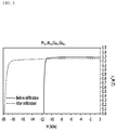
- FIGS. 5 and 6 are graphs showing the magnetic flux density (Y-axis) according to the coercive force (X-axis) measured before and after using a quaternary metal alloy powder as the auxiliary agents for infiltrating the sintered magnet.
- Y-axis the magnetic flux density
- X-axis the coercive force
Landscapes
- Engineering & Computer Science (AREA)
- Chemical & Material Sciences (AREA)
- Mechanical Engineering (AREA)
- Power Engineering (AREA)
- Manufacturing & Machinery (AREA)
- Materials Engineering (AREA)
- Metallurgy (AREA)
- Organic Chemistry (AREA)
- Crystallography & Structural Chemistry (AREA)
- Inorganic Chemistry (AREA)
- Chemical Kinetics & Catalysis (AREA)
- General Chemical & Material Sciences (AREA)
- Hard Magnetic Materials (AREA)
- Powder Metallurgy (AREA)
- Manufacturing Cores, Coils, And Magnets (AREA)
- Manufacture Of Metal Powder And Suspensions Thereof (AREA)
Abstract
Description
- This application claims the benefit of
Korean Patent Application No. 10-2019-0118839 filed on September 26, 2019 Korean Patent Application No. 10-2020-0122724 filed on September 23, 2020 - The present disclosure relates to a method for producing a sintered magnet and a sintered magnet produced thereby. More specifically, it relates to a method for producing a sintered magnet that improves magnetic properties using a sintering agent, and a sintered magnet produced by this method.
- NdFeB-based magnets are permanent magnets having a composition of Nd2Fe14B which is a compound of neodymium (Nd), a rare earth element, and iron and boron (B), and have been used as general-purpose permanent magnets for 30 years since there were developed in 1983. The NdFeB-based magnets are used in various fields such as electronic information, automobile industry, medical equipment, energy, and transportation. In particular, in line with recent trends in weight reduction and miniaturization, they are used in products such as machine tools, electronic information devices, electronic products for home appliances, mobile phones, robot motors, wind power generators, small motors for automobiles, and driving motors.
- For the general production of NdFeB-based magnets, a strip/mold casting or melt spinning method based on a metal powder metallurgy method is known. First, the strip/mold casting method is a process in which metals such as neodymium (Nd), iron (Fe), boron (B) are melted by heating to produce an ingot, crystal grain particles are coarsely pulverized and subjected to a miniaturization process to produce microparticles. These steps are repeated to obtain a magnet powder, which is subjected to a pressing and sintering process under a magnetic field to produce an anisotropic sintered magnet.
- In addition, the melt spinning method is a process in which metal elements are melted, then poured into a wheel rotating at a high speed, rapidly cooled, pulverized by a jet mill, then blended with a polymer to form a bonded magnet, or pressed to produce a magnet.
- However, all of these methods have problems that a pulverization process is essentially needed, it takes a long time in the pulverization process, and a process of coating the surface of the powder after pulverization is needed. Further, since the existing Nd2Fe14B microparticles are produced by a process in which the raw material (1500~2000°C) is melted and quenched, and the obtained lump is subjected to coarse pulverization, and hydrogen crushing/jet mill multi-step treatment, the particle shape is irregular and there is a limit to the miniaturization of particles.
- Recently, attention has been paid to the method of producing a magnet powder by a reduction-diffusion process. For example, uniform NdFeB fine particles can be produced through a reduction-diffusion process in which Nd2O3, Fe, and B are mixed and reduced with Ca or the like. However, an oxide film may be formed in the process of removing a reducing agent such as Ca and a reduced by-product used at the time of reduction in this method. The oxide film makes it difficult to sinter the magnetic powder, and the high oxygen content promotes the decomposition of columnar magnetic particles, and the properties of the sintered magnet obtained by sintering the magnetic powder may be deteriorated.
- Embodiments of the present disclosure has been designed to solve the above-mentioned problems, and an object of the present disclosure is to provide a method for producing a sintered magnet that improves the properties of a sintered magnet by adjusting the phase distributed in the grain boundary during sintering of magnetic powder, and a sintered magnet produced by this method.
- However, the problem to be solved by embodiments of the present disclosure is not limited to the above-described problems, and can be variously expanded within the scope of the technical idea included in the present disclosure.
- A method for producing a sintered magnet according to an embodiment of the present disclosure includes the steps of: producing an R-Fe-B-based magnet powder by a reduction-diffusion method, adding a R-Al-Cu powder as a sintering agent to the R-Fe-B-based magnet powder to form a mixed powder, and sintering the mixed powder to form a sintered magnet, wherein the R-Al-Cu powder is an alloy of R, Al and Cu, and the R is Nd, Pr, Dy, Tb or Ce.
- The method for producing a sintered magnet may further include a step of forming a R-Al-Cu powder as the sintering agent, wherein the step of forming the R-Al-Cu powder may include the steps of: mixing RH2 powder, Al powder, and Cu powder to form a sintered precursor, agglomerating the sintered precursor, raising the temperature of the agglomerated sintered precursor to form a metal alloy, and pulverizing the metal alloy to form the sintering agent.
- The method for producing a sintered magnet may further include the step of wrapping the sintered precursor in a metal foil when raising the temperature of the agglomerated sintered precursor.
- The step of forming the sintered precursor may further include a step of mixing a liquid Ga.
- The metal foil may be Mo or Ta.
- When wrapping the agglomerated sintered precursor in the metal foil and raising the temperature, the temperature may be raised in an argon gas atmosphere.
- The step of forming the metal alloy may further include the step of wrapping the agglomerated sintered precursor in the metal foil, raising the temperature up to 900 degrees Celsius to 1050 degrees Celsius, and then performing an additional heat treatment.
- The step of agglomerating the sintered precursor may use any one of hydraulic pressing, tapping, and cold isostatic pressing (CIP).
- The method for producing a sintered magnet may further include a step of adding NdH2 powder to the R-Al-Cu powder as the sintering agent.
- A sintered magnet according to another embodiment of the present disclosure is produced by the above-mentioned production method.
- According to the embodiments, in order to prevent the properties of the sintered magnet from being deteriorated by the oxide film generated when producing the magnetic powder as in the prior art, the powder of the metal alloy can be used as a sintering agent, thereby preventing the deterioration of the properties of the sintered magnet properties while lowering the melting temperature
-
-
FIG. 1 is a view showing a step of producing an R-Al-Cu metal alloy powder in a method of producing a sintered magnet according to an embodiment of the present disclosure. -
FIG. 2 is a BH graph showing the magnetic flux density (Y-axis) according to the coercive force (X-axis) measured in a sintered magnet produced according to Comparative Examples and Examples of the present disclosure. -
FIG. 3 is a BH graph showing the magnetic flux density (Y-axis) according to the coercive force (X-axis) measured in the sintered magnet produced according to Comparative Examples and Examples of the present disclosure, when changing the composition of the magnetic powder before sintering ofFIG. 2 . -
FIG. 4 is a BH graph showing the magnetic flux density (Y-axis) according to the coercive force (X-axis) measured in a sintered magnet produced by changing the type of rare earth metal contained in the metal alloy, when using the powder of a metal alloy according to an embodiment of the present disclosure as a sintering agent. -
FIGS. 5 and6 are graphs showing the magnetic flux density (Y-axis) according to the coercive force (X-axis) measured before and after using a quaternary metal alloy powder as the auxiliary agent for infiltrating the sintered magnet. - Hereinafter, various embodiments of the present disclosure will be described in detail so that those skilled in the art can easily implement them. The present disclosure may be modified in various different ways, and is not limited to the embodiments set forth herein.
- Further, throughout the specification, when a portion is referred to as "including" a certain component, it means that it can further include other components, without excluding the other components, unless otherwise stated.
- According to the present embodiment, a magnetic powder can be produced through a reduction-diffusion process using a low-cost rare earth oxide. An oxide film can be formed in the process of removing a reducing agent such as Ca and a reduced by-product used at the time of reduction by such a method. Such an oxide film makes it difficult to sinter the magnetic powder and may impair the properties of the sintered magnet. In order to supplement this, the present embodiment uses the powder of the metal alloy as a sintering agent, thereby being able to prevent the deterioration of the properties of the sintered magnet while lowering the melting temperature.
- When the oxygen content inside the magnet powder during sintering is increased, the magnetic properties are deteriorated, so it is necessary to use a high-purity metal alloy. However, in order to produce such an alloy, it is usually required to subject metal masses to arc melting or induction melting to melt it at high temperature. For example, in the case of the arc melting method, a process in which metal lumps are melted together in a vacuum atmosphere at about 2000 degrees Celsius to 3000 degrees Celsius by the generation of an arc through high pressure and high current, and the molten metal lumps are turned over and re-melted can be repeated. However, due to a space restriction on the arc melting machine, and a restriction on the maximum amount of sample for uniform melting, it can be produced only in small quantities. In addition, it is difficult to accurately control temperature during the arc melting process, and in the case of aluminum, it is vaporized in the process of melting due to the vapor pressure in a vacuum and causes a loss, thereby making it difficult to add an accurate ratio.
- On the other hand, according to the present embodiment, when the melting temperature is lowered during production of a metal alloy used as a sintering agent, the cost can be reduced. Specifically, according to the present embodiment, since the sintering agent is produced below 1050 degrees Celsius by using RH2 powder and respective metal powders, the economic efficiency can be improved at the process stage. Further, in the case of a metal material such as Ga that is liquid at room temperature, if arc melting is used, it is scattered during arc formation, which is technically difficult to make an alloy, whereas according to the present embodiment, it is possible to add an exact ratio.
- In the present embodiment, the metal alloy as a sintering agent corresponds to 1) a case in which 1) each metal powder corresponding to each element constituting the alloy is included as a sintering agent, or 2) a case in which a material corresponding to each element constituting the alloy is prepared as a precursor before sintering and metal alloy powder is included as a sintering agent.
-
FIG. 1 is a view showing a step of producing an R-Al-Cu metal alloy powder in a method of producing a sintered magnet according to an embodiment of the present disclosure. - According to one embodiment of the present disclosure corresponding to the above case 2), it includes a step of adding a R-Al-Cu metal alloy powder as a sintering agent to the R-Fe-B-based magnet powder to form a mixed powder. Specifically, the step of forming the R-Al-Cu powder includes the steps of: mixing RH2 powder, Al powder, and Cu powder to form a sintered precursor, agglomerating the sintered precursor, wrapping the agglomerated sintered precursor in a metal foil and raising the temperature to form a metal alloy, and pulverizing the metal alloy to form the sintering agent. The step of forming the sintered precursor may further include a step of mixing a liquid Ga. Further, the metal foil may include Mo or Ta.
- Referring to
FIG. 1 , a sintered precursor in which RH2 powder, Al powder, and Cu powder are mixed may be compressed by cold isostatic pressing (CIP) or the like, and the lump may be wrapped in a metal foil of Mo or Ta. Thelump 300 wrapped in metal foil is put in analumina crucible 100 and heated in atube furnace 200 under an argon (Ar) atmosphere to about 1050 degrees Celsius, thereby obtaining a high-purity alloy. At this time, thetube furnace 200 may be formed of a material such as alumina or SUS (stainless steel). - According to the present embodiment, it is advantageous to produce a large amount of metal alloys without space restrictions, and materials that are easily vaporized such as aluminum are also vaporized at high temperatures to minimize the lost part, so that an accurate addition ratio can be adjusted in the process progress. Further, since an electric furnace such as a tube furnace that can accurately control temperature and control a gas atmosphere during the process is used, a relatively low-cost device can be used. Further, not only elements such as aluminum that evaporate well, but also metal materials such as Ga that are liquid at room temperature, can be added at an accurate ratio. In addition, it is not necessary to use a vacuum state, and a metal alloy can be produced simply under normal pressure.
- When wrapping the agglomerated sintered precursor in the metal foil and raising the temperature, the temperature may be raised in an argon gas atmosphere.
- The forming of the metal alloy may further include the step of wrapping the agglomerated sintered precursor in the metal foil, raising the temperature up to 900 degrees Celsius to 1050 degrees Celsius, and then performing additional heat treatment. Here, the additional heat treatment is a heat treatment of the already synthesized alloy at a relatively low temperature, and a more uniform phase can be obtained through such annealing.
- The step of agglomerating the sintered precursor may be performed using any one pressing method of hydraulic pressing, tapping and cold isostatic pressing (CIP).
- The step of adding NdH2 powder to the R-Al-Cu powder as the sintering agent may be further included. Since it is not possible to sinter the magnet powder itself, the NdH2 powder contained in the sintering agent makes it possible to sinter a magnetic powder by mixing with a small amount of NdH2 powder.
- Since the composition of R07Al0.2Cu0.1 generally has the lowest melting point when R (rare earth) and Cu are mixed in a ratio of approximately 7:3, it is preferable to set R to 0.7. According to the present embodiment, from the composition of 100% of A1 and 0% of Cu to the composition of 50% of Al and 50% of Cu, they are melted together at less than 800 degrees Celsius to form an alloy, wherein Al can be prepared with a composition larger than that of Cu. If a large amount of Al and Cu are added as a sintering agent, the magnetic flux density may be lowered. Therefore, at the time of sintering, 0.17wt% of Al and 0.2wt% of Cu are added, and NdH2 is further added to set the reference value, followed by sintering.
- Hereinafter, the method of producing a sintered magnet according to one embodiment of the present disclosure will be described in more detail. However, the following examples correspond to examples for explaining the present disclosure, and the scope of the present disclosure are not limited thereto.
- A magnetic powder synthesized with the composition of Nd2.4Fe12.8BCu0.05 and a sintering agent were mixed in a mortar, and the mixture was placed in a molybdenum (Mo) crucible or a carbon (C) crucible as a mold for obtaining a magnet of a desired shape. Thereafter, the temperature was raised to 850 degrees Celsius at a temperature rising rate of 300 degrees Celsius/hour in an ultra-high vacuum state of approximately 10-6 torr or less, and then maintained for about 30 minutes. The temperature was raised again to 1070 degrees Celsius at the same temperature rising rate, maintained for two hours, and then naturally cooled to room temperature to obtain a sintered body (material after sintering). In the process of sintering, 6wt% of NdH2 was added as a sintering agent. All operation was carried out in an argon (Ar) atmosphere.
- Sintering was performed under approximately the same conditions as in Comparative Example 1, but in the process of sintering, 6wt% of NdH2 powder, 0.17wt% of Al powder, and 0.2wt% of Cu powder were added as a sintering agent.
- Sintering was performed under approximately the same conditions as in Comparative Example 1, but in the process of sintering, a metal alloy powder of NdH2 and Nd0.7Al0.2Cu0.1 was added as a sintering agent so that the amount was identical to that of Example 1. In other words, when sintering the mixture of the magnet powder and the sintering agent in Examples 1 and 2, the atomic weight ratio of each added metal element can be identical relative to the mass of the magnet powder.
- In order to prepare a metal alloy powder of NdH2 and Nd0.7Al0.2Cu0.1, the method for producing a sintering agent as follows was used. NdH2 powder, Al powder, and Cu powder were mixed, and the mixture was agglomerated by cold isostatic pressing (CIP). Thereafter, the agglomerated mixture was wrapped in Mo metal foil or Ta metal foil, and heated to 300 degrees Celsius per hour in an argon (Ar) gas atmosphere, and further heated at 900 degrees Celsius to 1050 degrees Celsius for an additional hour. The prepared metal alloy was pulverized to obtain a powder form.
- Sintering was performed under approximately the same conditions as in Comparative Example 1, but the magnetic powder synthesized with the composition of Nd2.4Fe12Co0.8BCu0.05 was used instead of the magnetic powder synthesized with the composition of Nd2.4Fe12.8BCu0.05. In addition, 10 wt% of NdH2 was added as a sintering agent.
- Sintering was performed under approximately the same conditions as in Comparative Example 2, but in the process of sintering, 10 wt% of NdH2 powder, 0.17 wt% of Al powder, and 0.2 wt% of Cu powder were added as a sintering agent.
- Sintering was performed under approximately the same conditions as in Example 3, but in the process of sintering, a metal alloy powder of NdH2 and Nd0.7Al0.2Cu0.1 was added as a sintering agent so that the amount was identical to that of Example 3. In order to prepare a metal alloy powder of NdH2 and Nd0.7Al0.2Cu0.1, the method for producing a sintering agent as follows was used. NdH2 powder, Al powder, and Cu powder were mixed, and the mixture was agglomerated by cold isostatic pressing (CIP). Thereafter, the agglomerated mixture was wrapped in Mo metal foil or Ta metal foil, and heated to 300 degrees Celsius per hour in an argon (Ar) gas atmosphere, and further heated at 900 degrees Celsius to 1050 degrees Celsius for an additional hour. The prepared metal alloy was pulverized to obtain a powder form.
- Sintering was performed under approximately the same conditions as in Example 4, but an alloy powder of NdH2 and Dy0.7Al0.2Cu0.1 was used as a sintering agent instead of the alloy powder of NdH2 and Nd0.7Al0.2Cu0.1.
- Sintering was performed under approximately the same conditions as in Example 4, but an alloy powder of NdH2 and Pr0.7Al0.2Cu0.1 was used as a sintering agent instead of the alloy powder of NdH2 and Nd0.7Al0.2Cu0.1.
-
FIG. 2 is a BH graph showing the magnetic flux density (Y-axis) according to the coercive force (X-axis) measured in a sintered magnet prepared according to Comparative Examples and Examples of the present disclosure. -
FIG. 2 shows the magnetic flux density (Y-axis) according to the coercive force (X-axis) measured in Comparative Example 1, Example 1, and Example 2, respectively. Referring toFIG. 2 , it can be confirmed that the properties of the sintered magnet are improved in Examples 1 and 2 compared to Comparative Example 1. Further, the case of sintering using the powder of a metal alloy as a sintering agent (Example 2) has improved properties of the sintered magnet as compared with the case of mixing and sintering the powder of a material corresponding to each sintering component element (Example 1). - When the amount of increase in the coercive force of Example 2 is converted into a percentage as compared with Example 1, an improvement of about 10 to 20% can be confirmed. That is, it is possible to obtain a meaningful increase in the coercive force according to the change in the shape of the sintering agent.
-
FIG. 3 is a BH graph showing the magnetic flux density (Y-axis) according to the coercive force (X-axis) measured in the sintered magnet produced according to Comparative Examples and Examples of the present disclosure, when changing the composition of the magnetic powder before sintering ofFIG. 2 . -
FIG. 3 shows the magnetic flux density (Y-axis) according to the coercive force (X-axis) measured in Comparative Example 2, Example 3, and Example 4, respectively. Referring toFIG. 3 , it can be confirmed that the properties of the sintered magnet are improved in Examples 3 and 4 compared to Comparative Example 2. Further, the case of sintering using the powder of a metal alloy as a sintering agent (Example 4) has improved properties of the sintered magnet as compared with the case of mixing and sintering the powder of a material corresponding to each sintering component element (Example 3). -
FIG. 4 is a BH graph showing the magnetic flux density (Y-axis) according to the coercive force (X-axis) measured in a sintered magnet produced by changing the type of rare earth metal contained in the metal alloy, when using the powder of a metal alloy according to an embodiment of the present disclosure as a sintering agent. -
FIG. 4 shows the magnetic flux density (Y axis) according to the coercive force (X axis) measured in Comparative Example 2, Example 4, Example 5, and Example 6, respectively. Referring toFIG. 4 , it can be confirmed that the properties of the sintered magnet are improved in Examples 4, 5 and 6 compared to Comparative Example 2. Further, when sintering using the powder of the metal alloy as a sintering agent, it can be confirmed that the properties of the sintered magnet are improved even if the type of rare earth metal contained in the metal alloy is changed. In particular, it can be confirmed that the properties of the sintered magnet are most improved when it is Dy among the rare earth metals included in the metal alloy. In addition, in the present embodiment, a sintering agent of a three-phase metal alloy, that is, R-Al-Cu (where R is Nd, Pr, Dy, Tb, or Ce) metal alloy, has been described, but a quaternary metal alloy with the addition of other metals such as Ga is also applicable as a modified example. - Hereinafter, a case where a quaternary metal alloy is formed in the method of producing a sintered magnet according to one embodiment of the present disclosure will be described. However, the following examples correspond to examples for explaining the present disclosure, and the scope of the present disclosure are not limited thereto.
- A sintered magnet was formed by sintering under approximately the same conditions as in Comparative Example 1, and then a metal alloy powder of Pr0.7Al0.2Cu0.1Ga0.1 was used as an auxiliary agent for infiltration.
- In order to prepare the metal alloy powder of Pr0.7Al0.2Cu0.1Ga0.1, the method for producing a sintering agent as follows was used. Pr powder, Al powder, Cu powder, and liquid Ga were mixed, and the mixture was agglomerated by a cold isostatic pressing (CIP). Then, the agglomerated mixture was wrapped in Mo metal foil or Ta metal foil, and heated to 300 degrees Celsius per hour in an argon (Ar) gas atmosphere, and further heated at 900 degrees Celsius to 1050 degrees Celsius for an additional hour. The prepared metal alloy was pulverized to obtain a powder form.
- Sintering was performed under approximately the same conditions as in Example 7, but an alloy powder of Dy0.7Al0.2Cu0.1Ga0.1 was used as an auxiliary agent for infiltration instead of the alloy powder of Pr0.7Al0.2Cu0.1Ga0.1.
-
FIGS. 5 and6 are graphs showing the magnetic flux density (Y-axis) according to the coercive force (X-axis) measured before and after using a quaternary metal alloy powder as the auxiliary agents for infiltrating the sintered magnet. InFIG. 5 , in order to confirm the level of the coercive force for the magnet infiltrated using the metal alloy powder of Pr0.7Al0.2Cu0.1Ga0.1 of Example 7, in a state in which an alloy powder of 2 wt% of Pr0.7Al0.2Cu0.1Ga0.1 relative to the sintered magnet was attached to the sintered magnet, infiltration was performed at 900 degrees Celsius for about 10 hours under high vacuum, and post-heat treatment was performed at approximately 520 degrees Celsius, and the resulting coercive force before and after is shown. InFIG. 6 , the coercive force level of the magnet infiltrated using the metal alloy powder of Dy0.7Al0.2Cu0.1Ga0.1 of Example 8 is shown. - Referring to
FIGS. 5 and6 , it can be confirmed that the coercive force is improved when the quaternary metal alloy powder is used as an auxiliary agent for infiltration. - Although the preferred embodiments of the present disclosure have been described in detail above, the scope of the present disclosure is not limited thereto, and various modifications and improvements of those skilled in the art using the basic concepts of the present disclosure defined in the following claims also belong to the scope of rights.
-
- 100:
- crucible
- 200:
- tube furnace
Claims (10)
- A method for producing a sintered magnet comprising the steps of:producing an R-Fe-B-based magnet powder by a reduction-diffusion method,adding a R-Al-Cu powder as a sintering agent to the R-Fe-B-based magnet powder to form a mixed powder, andsintering the mixed powder to form a sintered magnet,wherein the R-Al-Cu powder is an alloy of R, Al and Cu, and the R is Nd, Pr, Dy, Tb or Ce.
- The method for producing a sintered magnet according to claim 1,
further comprising a step of forming a R-Al-Cu powder as the sintering agent,
wherein the step of forming the R-Al-Cu powder comprises the steps of:mixing RH2 powder, Al powder, and Cu powder to form a sintered precursor, agglomerating the sintered precursor,raising the temperature of the agglomerated sintered precursor to form a metal alloy, and pulverizing the metal alloy to form the sintering agent. - The method for producing a sintered magnet according to claim 2,
further comprising a step of wrapping the sintered precursor in a metal foil when raising the temperature of the agglomerated sintered precursor. - The method for producing a sintered magnet according to claim 3,
wherein the step of forming the sintered precursor further comprises a step of mixing a liquid Ga. - The method for producing a sintered magnet according to claim 3,
wherein the metal foil is Mo or Ta. - The method for producing a sintered magnet according to claim 5,
wherein when wrapping the agglomerated sintered precursor in the metal foil and raising the temperature, the temperature is raised in an argon gas atmosphere. - The method for producing a sintered magnet according to claim 2,
wherein the step of forming the metal alloy further comprises the step of wrapping the agglomerated sintered precursor in the metal foil, raising the temperature up to 900 degrees Celsius to 1050 degrees Celsius, and then performing an additional heat treatment. - The method for producing a sintered magnet according to claim 2,
wherein the step of agglomerating the sintered precursor uses any one of hydraulic pressing, tapping, and cold isostatic pressing (CIP). - The method for producing a sintered magnet according to claim 1,
further comprising a step of adding a NdH2 powder to the R-Al-Cu powder as the sintering agent. - A sintered magnet produced by the production method according to claim 1.
Applications Claiming Priority (3)
| Application Number | Priority Date | Filing Date | Title |
|---|---|---|---|
| KR20190118839 | 2019-09-26 | ||
| KR1020200122724A KR102589893B1 (en) | 2019-09-26 | 2020-09-23 | Method for preparing sintered magnet and sintered magnet |
| PCT/KR2020/012913 WO2021060849A1 (en) | 2019-09-26 | 2020-09-24 | Sintered magnet manufacturing method and sintered magnet |
Publications (3)
| Publication Number | Publication Date |
|---|---|
| EP3855459A1 true EP3855459A1 (en) | 2021-07-28 |
| EP3855459A4 EP3855459A4 (en) | 2022-01-05 |
| EP3855459B1 EP3855459B1 (en) | 2024-01-10 |
Family
ID=75461985
Family Applications (1)
| Application Number | Title | Priority Date | Filing Date |
|---|---|---|---|
| EP20867972.0A Active EP3855459B1 (en) | 2019-09-26 | 2020-09-24 | Sintered magnet manufacturing method |
Country Status (5)
| Country | Link |
|---|---|
| US (1) | US12119150B2 (en) |
| EP (1) | EP3855459B1 (en) |
| JP (1) | JP7158807B2 (en) |
| KR (1) | KR102589893B1 (en) |
| CN (1) | CN112970081B (en) |
Families Citing this family (3)
| Publication number | Priority date | Publication date | Assignee | Title |
|---|---|---|---|---|
| KR102822215B1 (en) * | 2021-04-13 | 2025-06-18 | 주식회사 엘지화학 | Magnetic material and method for preparing the same |
| CN113571279B (en) * | 2021-07-23 | 2024-05-03 | 包头天和磁材科技股份有限公司 | Magnet and method for manufacturing the same |
| KR102754616B1 (en) * | 2023-10-18 | 2025-01-21 | 한국전력공사 | Super-conducting bulk magnet and Method for manufacturing the same |
Family Cites Families (29)
| Publication number | Priority date | Publication date | Assignee | Title |
|---|---|---|---|---|
| JPH04221805A (en) * | 1990-12-20 | 1992-08-12 | Tdk Corp | Manufacture of sintered rare-earth alloy and permanent magnet |
| JPH04293708A (en) * | 1991-03-22 | 1992-10-19 | Sumitomo Metal Mining Co Ltd | Rare earth-iron-boron alloy powder for press-molded sintered magnets and method for producing the same |
| JPH0513207A (en) | 1991-07-05 | 1993-01-22 | Hitachi Metals Ltd | Manufacture of r-t-b-based permanent magnet |
| US5482575A (en) * | 1992-12-08 | 1996-01-09 | Ugimag Sa | Fe-Re-B type magnetic powder, sintered magnets and preparation method thereof |
| JPH09275004A (en) | 1995-07-07 | 1997-10-21 | Daido Steel Co Ltd | Permanent magnet and its manufacturing method |
| KR100853089B1 (en) | 2001-07-10 | 2008-08-19 | 신에쓰 가가꾸 고교 가부시끼가이샤 | Rare earth magnets Scrap and / or sludge remelting methods and magnet alloys and rare earth sintered magnets |
| JP4208073B2 (en) | 2003-12-22 | 2009-01-14 | Tdk株式会社 | Housing structure for sintering and method for producing rare earth sintered magnet |
| US20120299675A1 (en) | 2009-12-09 | 2012-11-29 | Aichi Steel Corporation | Anisotropic rare earth magnet and method for producing the same |
| JP2011162811A (en) * | 2010-02-05 | 2011-08-25 | Sumitomo Metal Mining Co Ltd | Rare earth-iron based alloy powder for magnetic refrigeration |
| WO2012161355A1 (en) | 2011-05-25 | 2012-11-29 | Tdk株式会社 | Rare earth sintered magnet, method for manufacturing rare earth sintered magnet and rotary machine |
| JP6391915B2 (en) | 2012-06-15 | 2018-09-19 | 日産自動車株式会社 | Grain boundary modification method for Nd-Fe-B magnet |
| CN102800454B (en) * | 2012-08-30 | 2017-03-22 | 钢铁研究总院 | Low-cost double-main phase Ce permanent-magnet alloy and preparation method thereof |
| CN102881395B (en) | 2012-10-15 | 2015-10-21 | 南京信息工程大学 | A kind of alloy magnetic material and preparation method thereof |
| KR102215818B1 (en) | 2013-09-24 | 2021-02-17 | 엘지전자 주식회사 | Hot-deformed magnet comprising nonmagnetic alloys and fabricating method thereof |
| KR101624245B1 (en) * | 2015-01-09 | 2016-05-26 | 현대자동차주식회사 | Rare Earth Permanent Magnet and Method Thereof |
| CN104900359B (en) | 2015-05-07 | 2017-09-12 | 安泰科技股份有限公司 | The method that composition target gaseous phase deposition prepares grain boundary decision rare earth permanent-magnetic material |
| DE112016002876B4 (en) * | 2015-06-25 | 2025-12-04 | Proterial, Ltd. | R-T-B based sintered magnet and method for its production |
| JP2018026390A (en) | 2016-08-08 | 2018-02-15 | 日立金属株式会社 | Method for manufacturing r-t-b based sintered magnet |
| KR102100759B1 (en) * | 2016-11-08 | 2020-04-14 | 주식회사 엘지화학 | Manufacturing method of metal powder and metal powder |
| CN106710768A (en) * | 2016-12-27 | 2017-05-24 | 浙江大学 | Method for improving neodymium, cerium, iron and boron sintered magnet coercivity by adding neodymium hydride |
| JP2018186200A (en) | 2017-04-26 | 2018-11-22 | トヨタ自動車株式会社 | Rare earth magnet manufacturing method |
| KR101918975B1 (en) | 2017-08-09 | 2018-11-16 | 한국기계연구원 | MAGNET of Nd-Fe-B SYSTEM AND THE MANUFACTURING METHOD THEREOF |
| WO2019107929A1 (en) | 2017-11-28 | 2019-06-06 | 주식회사 엘지화학 | Method for manufacturing sintered magnet and sintered magnet |
| KR102093491B1 (en) | 2017-11-28 | 2020-03-25 | 주식회사 엘지화학 | Manufacturing method of sintered magnet and sintered magnet |
| CN110021466A (en) | 2017-12-28 | 2019-07-16 | 厦门钨业股份有限公司 | A kind of R-Fe-B-Cu-Al system sintered magnet and preparation method thereof |
| KR102356630B1 (en) | 2018-01-10 | 2022-01-26 | 주식회사 엘지화학 | Rare-earth magnet |
| JP2020052131A (en) | 2018-09-25 | 2020-04-02 | 富士ゼロックス株式会社 | Cleaning body, cleaning device, charging device, assembly, and image forming device |
| CN109509628B (en) | 2018-12-21 | 2020-10-23 | 宁波韵升股份有限公司 | Preparation method of sintered neodymium iron boron composite powder |
| CN109852809A (en) * | 2019-04-10 | 2019-06-07 | 江苏集萃安泰创明先进能源材料研究院有限公司 | A kind of short route recycles the method for neodymium iron boron alloy powder and the preparation method of recycled sinter magnet from neodymium iron boron greasy filth waste material |
-
2020
- 2020-09-23 KR KR1020200122724A patent/KR102589893B1/en active Active
- 2020-09-24 JP JP2021531588A patent/JP7158807B2/en active Active
- 2020-09-24 CN CN202080006088.1A patent/CN112970081B/en active Active
- 2020-09-24 US US17/288,661 patent/US12119150B2/en active Active
- 2020-09-24 EP EP20867972.0A patent/EP3855459B1/en active Active
Also Published As
| Publication number | Publication date |
|---|---|
| KR102589893B1 (en) | 2023-10-16 |
| CN112970081B (en) | 2023-09-19 |
| KR20210036824A (en) | 2021-04-05 |
| EP3855459B1 (en) | 2024-01-10 |
| US20210398718A1 (en) | 2021-12-23 |
| JP7158807B2 (en) | 2022-10-24 |
| CN112970081A (en) | 2021-06-15 |
| JP2022511483A (en) | 2022-01-31 |
| US12119150B2 (en) | 2024-10-15 |
| EP3855459A4 (en) | 2022-01-05 |
Similar Documents
| Publication | Publication Date | Title |
|---|---|---|
| JP5477282B2 (en) | R-T-B system sintered magnet and manufacturing method thereof | |
| KR102093491B1 (en) | Manufacturing method of sintered magnet and sintered magnet | |
| EP3473361B1 (en) | Method for preparing nd2fe14b metal powder | |
| EP3855459B1 (en) | Sintered magnet manufacturing method | |
| CN107689279A (en) | One kind improves the coercitive method of sintered NdFeB built-up magnet | |
| JP2022119057A (en) | Method for manufacturing rare earth permanent magnet | |
| CN105118655A (en) | Method for preparing high-coercivity magnet by modifying nano zinc powder crystal boundary | |
| EP3754676B1 (en) | Method for manufacturing sintered magnet | |
| EP4006931B1 (en) | Manufacturing method of sintered magnet | |
| EP3677365B1 (en) | Method for manufacturing magnet powder and magnet powder | |
| KR20200023109A (en) | Method for preparing magnetic material and magnetic material | |
| EP3855460B1 (en) | Manufacturing method for sintered magnet | |
| KR102399418B1 (en) | Manufacturing method of sintered magnetic and sintered magnetic manufactured by the same | |
| JP2014045139A (en) | Magnetic material | |
| JPH0521219A (en) | Rare earth permanent magnet manufacturing method | |
| WO2021060849A1 (en) | Sintered magnet manufacturing method and sintered magnet | |
| KR20200029833A (en) | Manufacturing method of sintered magnet and sintered magnet | |
| KR20190061846A (en) | Manufacturing method of magnetic powder and magnetic powder |
Legal Events
| Date | Code | Title | Description |
|---|---|---|---|
| STAA | Information on the status of an ep patent application or granted ep patent |
Free format text: STATUS: THE INTERNATIONAL PUBLICATION HAS BEEN MADE |
|
| PUAI | Public reference made under article 153(3) epc to a published international application that has entered the european phase |
Free format text: ORIGINAL CODE: 0009012 |
|
| STAA | Information on the status of an ep patent application or granted ep patent |
Free format text: STATUS: REQUEST FOR EXAMINATION WAS MADE |
|
| 17P | Request for examination filed |
Effective date: 20210420 |
|
| AK | Designated contracting states |
Kind code of ref document: A1 Designated state(s): AL AT BE BG CH CY CZ DE DK EE ES FI FR GB GR HR HU IE IS IT LI LT LU LV MC MK MT NL NO PL PT RO RS SE SI SK SM TR |
|
| A4 | Supplementary search report drawn up and despatched |
Effective date: 20211203 |
|
| RIC1 | Information provided on ipc code assigned before grant |
Ipc: C22C 1/05 20060101ALI20211129BHEP Ipc: B22F 3/10 20060101ALI20211129BHEP Ipc: H01F 1/057 20060101ALI20211129BHEP Ipc: H01F 41/02 20060101AFI20211129BHEP |
|
| DAV | Request for validation of the european patent (deleted) | ||
| DAX | Request for extension of the european patent (deleted) | ||
| REG | Reference to a national code |
Ref country code: DE Ref legal event code: R079 Free format text: PREVIOUS MAIN CLASS: H01F0041020000 Ipc: H01F0001057000 Ref country code: DE Ref legal event code: R079 Ref document number: 602020024327 Country of ref document: DE Free format text: PREVIOUS MAIN CLASS: H01F0041020000 Ipc: H01F0001057000 |
|
| GRAP | Despatch of communication of intention to grant a patent |
Free format text: ORIGINAL CODE: EPIDOSNIGR1 |
|
| STAA | Information on the status of an ep patent application or granted ep patent |
Free format text: STATUS: GRANT OF PATENT IS INTENDED |
|
| RIC1 | Information provided on ipc code assigned before grant |
Ipc: B22F 3/10 20060101ALI20230921BHEP Ipc: H01F 41/02 20060101ALI20230921BHEP Ipc: H01F 1/057 20060101AFI20230921BHEP |
|
| INTG | Intention to grant announced |
Effective date: 20231023 |
|
| GRAS | Grant fee paid |
Free format text: ORIGINAL CODE: EPIDOSNIGR3 |
|
| GRAA | (expected) grant |
Free format text: ORIGINAL CODE: 0009210 |
|
| STAA | Information on the status of an ep patent application or granted ep patent |
Free format text: STATUS: THE PATENT HAS BEEN GRANTED |
|
| AK | Designated contracting states |
Kind code of ref document: B1 Designated state(s): AL AT BE BG CH CY CZ DE DK EE ES FI FR GB GR HR HU IE IS IT LI LT LU LV MC MK MT NL NO PL PT RO RS SE SI SK SM TR |
|
| REG | Reference to a national code |
Ref country code: GB Ref legal event code: FG4D |
|
| REG | Reference to a national code |
Ref country code: CH Ref legal event code: EP |
|
| REG | Reference to a national code |
Ref country code: DE Ref legal event code: R096 Ref document number: 602020024327 Country of ref document: DE |
|
| REG | Reference to a national code |
Ref country code: IE Ref legal event code: FG4D |
|
| REG | Reference to a national code |
Ref country code: LT Ref legal event code: MG9D |
|
| REG | Reference to a national code |
Ref country code: NL Ref legal event code: MP Effective date: 20240110 |
|
| REG | Reference to a national code |
Ref country code: AT Ref legal event code: MK05 Ref document number: 1649576 Country of ref document: AT Kind code of ref document: T Effective date: 20240110 |
|
| PG25 | Lapsed in a contracting state [announced via postgrant information from national office to epo] |
Ref country code: NL Free format text: LAPSE BECAUSE OF FAILURE TO SUBMIT A TRANSLATION OF THE DESCRIPTION OR TO PAY THE FEE WITHIN THE PRESCRIBED TIME-LIMIT Effective date: 20240110 |
|
| PG25 | Lapsed in a contracting state [announced via postgrant information from national office to epo] |
Ref country code: NL Free format text: LAPSE BECAUSE OF FAILURE TO SUBMIT A TRANSLATION OF THE DESCRIPTION OR TO PAY THE FEE WITHIN THE PRESCRIBED TIME-LIMIT Effective date: 20240110 |
|
| PG25 | Lapsed in a contracting state [announced via postgrant information from national office to epo] |
Ref country code: IS Free format text: LAPSE BECAUSE OF FAILURE TO SUBMIT A TRANSLATION OF THE DESCRIPTION OR TO PAY THE FEE WITHIN THE PRESCRIBED TIME-LIMIT Effective date: 20240510 |
|
| PG25 | Lapsed in a contracting state [announced via postgrant information from national office to epo] |
Ref country code: LT Free format text: LAPSE BECAUSE OF FAILURE TO SUBMIT A TRANSLATION OF THE DESCRIPTION OR TO PAY THE FEE WITHIN THE PRESCRIBED TIME-LIMIT Effective date: 20240110 |
|
| PG25 | Lapsed in a contracting state [announced via postgrant information from national office to epo] |
Ref country code: GR Free format text: LAPSE BECAUSE OF FAILURE TO SUBMIT A TRANSLATION OF THE DESCRIPTION OR TO PAY THE FEE WITHIN THE PRESCRIBED TIME-LIMIT Effective date: 20240411 |
|
| PG25 | Lapsed in a contracting state [announced via postgrant information from national office to epo] |
Ref country code: HR Free format text: LAPSE BECAUSE OF FAILURE TO SUBMIT A TRANSLATION OF THE DESCRIPTION OR TO PAY THE FEE WITHIN THE PRESCRIBED TIME-LIMIT Effective date: 20240110 Ref country code: RS Free format text: LAPSE BECAUSE OF FAILURE TO SUBMIT A TRANSLATION OF THE DESCRIPTION OR TO PAY THE FEE WITHIN THE PRESCRIBED TIME-LIMIT Effective date: 20240410 |
|
| PG25 | Lapsed in a contracting state [announced via postgrant information from national office to epo] |
Ref country code: ES Free format text: LAPSE BECAUSE OF FAILURE TO SUBMIT A TRANSLATION OF THE DESCRIPTION OR TO PAY THE FEE WITHIN THE PRESCRIBED TIME-LIMIT Effective date: 20240110 |
|
| PG25 | Lapsed in a contracting state [announced via postgrant information from national office to epo] |
Ref country code: AT Free format text: LAPSE BECAUSE OF FAILURE TO SUBMIT A TRANSLATION OF THE DESCRIPTION OR TO PAY THE FEE WITHIN THE PRESCRIBED TIME-LIMIT Effective date: 20240110 |
|
| PG25 | Lapsed in a contracting state [announced via postgrant information from national office to epo] |
Ref country code: RS Free format text: LAPSE BECAUSE OF FAILURE TO SUBMIT A TRANSLATION OF THE DESCRIPTION OR TO PAY THE FEE WITHIN THE PRESCRIBED TIME-LIMIT Effective date: 20240410 Ref country code: NO Free format text: LAPSE BECAUSE OF FAILURE TO SUBMIT A TRANSLATION OF THE DESCRIPTION OR TO PAY THE FEE WITHIN THE PRESCRIBED TIME-LIMIT Effective date: 20240410 Ref country code: LT Free format text: LAPSE BECAUSE OF FAILURE TO SUBMIT A TRANSLATION OF THE DESCRIPTION OR TO PAY THE FEE WITHIN THE PRESCRIBED TIME-LIMIT Effective date: 20240110 Ref country code: IS Free format text: LAPSE BECAUSE OF FAILURE TO SUBMIT A TRANSLATION OF THE DESCRIPTION OR TO PAY THE FEE WITHIN THE PRESCRIBED TIME-LIMIT Effective date: 20240510 Ref country code: HR Free format text: LAPSE BECAUSE OF FAILURE TO SUBMIT A TRANSLATION OF THE DESCRIPTION OR TO PAY THE FEE WITHIN THE PRESCRIBED TIME-LIMIT Effective date: 20240110 Ref country code: GR Free format text: LAPSE BECAUSE OF FAILURE TO SUBMIT A TRANSLATION OF THE DESCRIPTION OR TO PAY THE FEE WITHIN THE PRESCRIBED TIME-LIMIT Effective date: 20240411 Ref country code: ES Free format text: LAPSE BECAUSE OF FAILURE TO SUBMIT A TRANSLATION OF THE DESCRIPTION OR TO PAY THE FEE WITHIN THE PRESCRIBED TIME-LIMIT Effective date: 20240110 Ref country code: BG Free format text: LAPSE BECAUSE OF FAILURE TO SUBMIT A TRANSLATION OF THE DESCRIPTION OR TO PAY THE FEE WITHIN THE PRESCRIBED TIME-LIMIT Effective date: 20240110 Ref country code: AT Free format text: LAPSE BECAUSE OF FAILURE TO SUBMIT A TRANSLATION OF THE DESCRIPTION OR TO PAY THE FEE WITHIN THE PRESCRIBED TIME-LIMIT Effective date: 20240110 |
|
| PG25 | Lapsed in a contracting state [announced via postgrant information from national office to epo] |
Ref country code: PL Free format text: LAPSE BECAUSE OF FAILURE TO SUBMIT A TRANSLATION OF THE DESCRIPTION OR TO PAY THE FEE WITHIN THE PRESCRIBED TIME-LIMIT Effective date: 20240110 Ref country code: PT Free format text: LAPSE BECAUSE OF FAILURE TO SUBMIT A TRANSLATION OF THE DESCRIPTION OR TO PAY THE FEE WITHIN THE PRESCRIBED TIME-LIMIT Effective date: 20240510 |
|
| PG25 | Lapsed in a contracting state [announced via postgrant information from national office to epo] |
Ref country code: SE Free format text: LAPSE BECAUSE OF FAILURE TO SUBMIT A TRANSLATION OF THE DESCRIPTION OR TO PAY THE FEE WITHIN THE PRESCRIBED TIME-LIMIT Effective date: 20240110 Ref country code: PT Free format text: LAPSE BECAUSE OF FAILURE TO SUBMIT A TRANSLATION OF THE DESCRIPTION OR TO PAY THE FEE WITHIN THE PRESCRIBED TIME-LIMIT Effective date: 20240510 Ref country code: PL Free format text: LAPSE BECAUSE OF FAILURE TO SUBMIT A TRANSLATION OF THE DESCRIPTION OR TO PAY THE FEE WITHIN THE PRESCRIBED TIME-LIMIT Effective date: 20240110 Ref country code: LV Free format text: LAPSE BECAUSE OF FAILURE TO SUBMIT A TRANSLATION OF THE DESCRIPTION OR TO PAY THE FEE WITHIN THE PRESCRIBED TIME-LIMIT Effective date: 20240110 |
|
| PG25 | Lapsed in a contracting state [announced via postgrant information from national office to epo] |
Ref country code: DK Free format text: LAPSE BECAUSE OF FAILURE TO SUBMIT A TRANSLATION OF THE DESCRIPTION OR TO PAY THE FEE WITHIN THE PRESCRIBED TIME-LIMIT Effective date: 20240110 |
|
| REG | Reference to a national code |
Ref country code: DE Ref legal event code: R097 Ref document number: 602020024327 Country of ref document: DE |
|
| PG25 | Lapsed in a contracting state [announced via postgrant information from national office to epo] |
Ref country code: SM Free format text: LAPSE BECAUSE OF FAILURE TO SUBMIT A TRANSLATION OF THE DESCRIPTION OR TO PAY THE FEE WITHIN THE PRESCRIBED TIME-LIMIT Effective date: 20240110 |
|
| PG25 | Lapsed in a contracting state [announced via postgrant information from national office to epo] |
Ref country code: EE Free format text: LAPSE BECAUSE OF FAILURE TO SUBMIT A TRANSLATION OF THE DESCRIPTION OR TO PAY THE FEE WITHIN THE PRESCRIBED TIME-LIMIT Effective date: 20240110 Ref country code: CZ Free format text: LAPSE BECAUSE OF FAILURE TO SUBMIT A TRANSLATION OF THE DESCRIPTION OR TO PAY THE FEE WITHIN THE PRESCRIBED TIME-LIMIT Effective date: 20240110 |
|
| PG25 | Lapsed in a contracting state [announced via postgrant information from national office to epo] |
Ref country code: SK Free format text: LAPSE BECAUSE OF FAILURE TO SUBMIT A TRANSLATION OF THE DESCRIPTION OR TO PAY THE FEE WITHIN THE PRESCRIBED TIME-LIMIT Effective date: 20240110 |
|
| PG25 | Lapsed in a contracting state [announced via postgrant information from national office to epo] |
Ref country code: SM Free format text: LAPSE BECAUSE OF FAILURE TO SUBMIT A TRANSLATION OF THE DESCRIPTION OR TO PAY THE FEE WITHIN THE PRESCRIBED TIME-LIMIT Effective date: 20240110 Ref country code: SK Free format text: LAPSE BECAUSE OF FAILURE TO SUBMIT A TRANSLATION OF THE DESCRIPTION OR TO PAY THE FEE WITHIN THE PRESCRIBED TIME-LIMIT Effective date: 20240110 Ref country code: RO Free format text: LAPSE BECAUSE OF FAILURE TO SUBMIT A TRANSLATION OF THE DESCRIPTION OR TO PAY THE FEE WITHIN THE PRESCRIBED TIME-LIMIT Effective date: 20240110 Ref country code: EE Free format text: LAPSE BECAUSE OF FAILURE TO SUBMIT A TRANSLATION OF THE DESCRIPTION OR TO PAY THE FEE WITHIN THE PRESCRIBED TIME-LIMIT Effective date: 20240110 Ref country code: DK Free format text: LAPSE BECAUSE OF FAILURE TO SUBMIT A TRANSLATION OF THE DESCRIPTION OR TO PAY THE FEE WITHIN THE PRESCRIBED TIME-LIMIT Effective date: 20240110 Ref country code: CZ Free format text: LAPSE BECAUSE OF FAILURE TO SUBMIT A TRANSLATION OF THE DESCRIPTION OR TO PAY THE FEE WITHIN THE PRESCRIBED TIME-LIMIT Effective date: 20240110 |
|
| PLBE | No opposition filed within time limit |
Free format text: ORIGINAL CODE: 0009261 |
|
| STAA | Information on the status of an ep patent application or granted ep patent |
Free format text: STATUS: NO OPPOSITION FILED WITHIN TIME LIMIT |
|
| PG25 | Lapsed in a contracting state [announced via postgrant information from national office to epo] |
Ref country code: IT Free format text: LAPSE BECAUSE OF FAILURE TO SUBMIT A TRANSLATION OF THE DESCRIPTION OR TO PAY THE FEE WITHIN THE PRESCRIBED TIME-LIMIT Effective date: 20240110 |
|
| 26N | No opposition filed |
Effective date: 20241011 |
|
| PG25 | Lapsed in a contracting state [announced via postgrant information from national office to epo] |
Ref country code: IT Free format text: LAPSE BECAUSE OF FAILURE TO SUBMIT A TRANSLATION OF THE DESCRIPTION OR TO PAY THE FEE WITHIN THE PRESCRIBED TIME-LIMIT Effective date: 20240110 |
|
| PG25 | Lapsed in a contracting state [announced via postgrant information from national office to epo] |
Ref country code: MC Free format text: LAPSE BECAUSE OF FAILURE TO SUBMIT A TRANSLATION OF THE DESCRIPTION OR TO PAY THE FEE WITHIN THE PRESCRIBED TIME-LIMIT Effective date: 20240110 Ref country code: SI Free format text: LAPSE BECAUSE OF FAILURE TO SUBMIT A TRANSLATION OF THE DESCRIPTION OR TO PAY THE FEE WITHIN THE PRESCRIBED TIME-LIMIT Effective date: 20240110 |
|
| REG | Reference to a national code |
Ref country code: CH Ref legal event code: PL |
|
| PG25 | Lapsed in a contracting state [announced via postgrant information from national office to epo] |
Ref country code: LU Free format text: LAPSE BECAUSE OF NON-PAYMENT OF DUE FEES Effective date: 20240924 |
|
| GBPC | Gb: european patent ceased through non-payment of renewal fee |
Effective date: 20240924 |
|
| PG25 | Lapsed in a contracting state [announced via postgrant information from national office to epo] |
Ref country code: GB Free format text: LAPSE BECAUSE OF NON-PAYMENT OF DUE FEES Effective date: 20240924 |
|
| REG | Reference to a national code |
Ref country code: BE Ref legal event code: MM Effective date: 20240930 |
|
| PG25 | Lapsed in a contracting state [announced via postgrant information from national office to epo] |
Ref country code: BE Free format text: LAPSE BECAUSE OF NON-PAYMENT OF DUE FEES Effective date: 20240930 |
|
| PG25 | Lapsed in a contracting state [announced via postgrant information from national office to epo] |
Ref country code: CH Free format text: LAPSE BECAUSE OF NON-PAYMENT OF DUE FEES Effective date: 20240930 |
|
| PG25 | Lapsed in a contracting state [announced via postgrant information from national office to epo] |
Ref country code: IE Free format text: LAPSE BECAUSE OF NON-PAYMENT OF DUE FEES Effective date: 20240924 |
|
| PG25 | Lapsed in a contracting state [announced via postgrant information from national office to epo] |
Ref country code: FI Free format text: LAPSE BECAUSE OF FAILURE TO SUBMIT A TRANSLATION OF THE DESCRIPTION OR TO PAY THE FEE WITHIN THE PRESCRIBED TIME-LIMIT Effective date: 20240110 |
|
| PGFP | Annual fee paid to national office [announced via postgrant information from national office to epo] |
Ref country code: DE Payment date: 20250820 Year of fee payment: 6 |
|
| PGFP | Annual fee paid to national office [announced via postgrant information from national office to epo] |
Ref country code: FR Payment date: 20250821 Year of fee payment: 6 |
|
| PG25 | Lapsed in a contracting state [announced via postgrant information from national office to epo] |
Ref country code: CY Free format text: LAPSE BECAUSE OF FAILURE TO SUBMIT A TRANSLATION OF THE DESCRIPTION OR TO PAY THE FEE WITHIN THE PRESCRIBED TIME-LIMIT; INVALID AB INITIO Effective date: 20200924 |
|
| PG25 | Lapsed in a contracting state [announced via postgrant information from national office to epo] |
Ref country code: HU Free format text: LAPSE BECAUSE OF FAILURE TO SUBMIT A TRANSLATION OF THE DESCRIPTION OR TO PAY THE FEE WITHIN THE PRESCRIBED TIME-LIMIT; INVALID AB INITIO Effective date: 20200924 |