EP3855342A1 - Reading of optical codes - Google Patents
Reading of optical codes Download PDFInfo
- Publication number
- EP3855342A1 EP3855342A1 EP20153885.7A EP20153885A EP3855342A1 EP 3855342 A1 EP3855342 A1 EP 3855342A1 EP 20153885 A EP20153885 A EP 20153885A EP 3855342 A1 EP3855342 A1 EP 3855342A1
- Authority
- EP
- European Patent Office
- Prior art keywords
- code
- pattern
- scanning
- sampling
- image data
- Prior art date
- Legal status (The legal status is an assumption and is not a legal conclusion. Google has not performed a legal analysis and makes no representation as to the accuracy of the status listed.)
- Granted
Links
- 230000003287 optical effect Effects 0.000 title claims abstract description 8
- 238000000034 method Methods 0.000 claims abstract description 33
- 238000005070 sampling Methods 0.000 claims description 50
- 239000011159 matrix material Substances 0.000 claims description 19
- 238000011156 evaluation Methods 0.000 claims description 9
- 238000006073 displacement reaction Methods 0.000 claims description 4
- 230000006978 adaptation Effects 0.000 description 11
- 230000008569 process Effects 0.000 description 5
- 238000012937 correction Methods 0.000 description 4
- 230000008901 benefit Effects 0.000 description 3
- 238000012545 processing Methods 0.000 description 3
- 230000000295 complement effect Effects 0.000 description 2
- 238000003384 imaging method Methods 0.000 description 2
- 230000006872 improvement Effects 0.000 description 2
- 230000007246 mechanism Effects 0.000 description 2
- 238000004806 packaging method and process Methods 0.000 description 2
- 238000013459 approach Methods 0.000 description 1
- 238000006243 chemical reaction Methods 0.000 description 1
- 230000006866 deterioration Effects 0.000 description 1
- 238000004049 embossing Methods 0.000 description 1
- 238000009472 formulation Methods 0.000 description 1
- 238000009432 framing Methods 0.000 description 1
- 230000005484 gravity Effects 0.000 description 1
- 238000009499 grossing Methods 0.000 description 1
- 230000001788 irregular Effects 0.000 description 1
- 238000012804 iterative process Methods 0.000 description 1
- 238000005259 measurement Methods 0.000 description 1
- 239000000203 mixture Substances 0.000 description 1
- 230000005693 optoelectronics Effects 0.000 description 1
- 238000007781 pre-processing Methods 0.000 description 1
- 238000001454 recorded image Methods 0.000 description 1
- 239000000758 substrate Substances 0.000 description 1
- 230000009466 transformation Effects 0.000 description 1
Images


Classifications
-
- G—PHYSICS
- G06—COMPUTING; CALCULATING OR COUNTING
- G06K—GRAPHICAL DATA READING; PRESENTATION OF DATA; RECORD CARRIERS; HANDLING RECORD CARRIERS
- G06K7/00—Methods or arrangements for sensing record carriers, e.g. for reading patterns
- G06K7/10—Methods or arrangements for sensing record carriers, e.g. for reading patterns by electromagnetic radiation, e.g. optical sensing; by corpuscular radiation
- G06K7/10544—Methods or arrangements for sensing record carriers, e.g. for reading patterns by electromagnetic radiation, e.g. optical sensing; by corpuscular radiation by scanning of the records by radiation in the optical part of the electromagnetic spectrum
- G06K7/10821—Methods or arrangements for sensing record carriers, e.g. for reading patterns by electromagnetic radiation, e.g. optical sensing; by corpuscular radiation by scanning of the records by radiation in the optical part of the electromagnetic spectrum further details of bar or optical code scanning devices
-
- G—PHYSICS
- G06—COMPUTING; CALCULATING OR COUNTING
- G06K—GRAPHICAL DATA READING; PRESENTATION OF DATA; RECORD CARRIERS; HANDLING RECORD CARRIERS
- G06K7/00—Methods or arrangements for sensing record carriers, e.g. for reading patterns
- G06K7/10—Methods or arrangements for sensing record carriers, e.g. for reading patterns by electromagnetic radiation, e.g. optical sensing; by corpuscular radiation
- G06K7/14—Methods or arrangements for sensing record carriers, e.g. for reading patterns by electromagnetic radiation, e.g. optical sensing; by corpuscular radiation using light without selection of wavelength, e.g. sensing reflected white light
- G06K7/1404—Methods for optical code recognition
- G06K7/146—Methods for optical code recognition the method including quality enhancement steps
-
- G—PHYSICS
- G06—COMPUTING; CALCULATING OR COUNTING
- G06K—GRAPHICAL DATA READING; PRESENTATION OF DATA; RECORD CARRIERS; HANDLING RECORD CARRIERS
- G06K7/00—Methods or arrangements for sensing record carriers, e.g. for reading patterns
- G06K7/10—Methods or arrangements for sensing record carriers, e.g. for reading patterns by electromagnetic radiation, e.g. optical sensing; by corpuscular radiation
- G06K7/10544—Methods or arrangements for sensing record carriers, e.g. for reading patterns by electromagnetic radiation, e.g. optical sensing; by corpuscular radiation by scanning of the records by radiation in the optical part of the electromagnetic spectrum
- G06K7/10712—Fixed beam scanning
- G06K7/10722—Photodetector array or CCD scanning
-
- G—PHYSICS
- G06—COMPUTING; CALCULATING OR COUNTING
- G06K—GRAPHICAL DATA READING; PRESENTATION OF DATA; RECORD CARRIERS; HANDLING RECORD CARRIERS
- G06K7/00—Methods or arrangements for sensing record carriers, e.g. for reading patterns
- G06K7/10—Methods or arrangements for sensing record carriers, e.g. for reading patterns by electromagnetic radiation, e.g. optical sensing; by corpuscular radiation
- G06K7/14—Methods or arrangements for sensing record carriers, e.g. for reading patterns by electromagnetic radiation, e.g. optical sensing; by corpuscular radiation using light without selection of wavelength, e.g. sensing reflected white light
- G06K7/1404—Methods for optical code recognition
- G06K7/1408—Methods for optical code recognition the method being specifically adapted for the type of code
- G06K7/1413—1D bar codes
-
- G—PHYSICS
- G06—COMPUTING; CALCULATING OR COUNTING
- G06K—GRAPHICAL DATA READING; PRESENTATION OF DATA; RECORD CARRIERS; HANDLING RECORD CARRIERS
- G06K7/00—Methods or arrangements for sensing record carriers, e.g. for reading patterns
- G06K7/10—Methods or arrangements for sensing record carriers, e.g. for reading patterns by electromagnetic radiation, e.g. optical sensing; by corpuscular radiation
- G06K7/14—Methods or arrangements for sensing record carriers, e.g. for reading patterns by electromagnetic radiation, e.g. optical sensing; by corpuscular radiation using light without selection of wavelength, e.g. sensing reflected white light
- G06K7/1404—Methods for optical code recognition
- G06K7/1408—Methods for optical code recognition the method being specifically adapted for the type of code
- G06K7/1417—2D bar codes
-
- G—PHYSICS
- G06—COMPUTING; CALCULATING OR COUNTING
- G06T—IMAGE DATA PROCESSING OR GENERATION, IN GENERAL
- G06T7/00—Image analysis
- G06T7/70—Determining position or orientation of objects or cameras
Definitions
- the invention relates to a method and a code reading device for reading optical codes, in particular 2D codes, with distortions due to an uneven background of the code according to the preamble of claims 1 and 14, respectively.
- Code readers are known from supermarket checkouts, for automatic parcel identification, sorting of mail, baggage handling in airports and other logistics applications.
- a reading beam is guided across the code by means of a rotating mirror or a polygon mirror wheel.
- a camera-based code reader uses an image sensor to record images of the objects with the codes on them, and image evaluation software extracts the code information from these images.
- Camera-based code readers can also easily cope with other types of code than one-dimensional barcodes, which, like a matrix code, are also structured two-dimensionally and provide more information.
- the code-carrying objects are conveyed past the code reader.
- a code scanner records the codes that are fed into its reading area one after the other.
- a line camera reads in the object images with the code information successively and line by line with the relative movement in a camera-based code reader.
- a two-dimensional image sensor is used to regularly record image data that more or less overlap depending on the recording frequency and conveying speed. So that the objects can be arranged in any orientation on the conveyor, several code readers are often provided on a reading tunnel in order to pick up objects from several or all sides. It is also known to combine the reading fields of several code readers, for example to cover a wider conveyor belt.
- Error correction mechanisms are now built into the various 2D code specifications. However, they are not structured in such a way that complex deformations can be detected, but implicitly a minimal influence of a non-planar surface is assumed. However, there are applications in which this silent requirement is not met, and not just in individual cases.
- a typical example are codes on soft packaging such as plastic sleeves. Then the intended mechanisms, such as Reed-Solomon error correction, quickly reach their limits, and after a certain deformation, the 2D codes can no longer be read.
- Another conventional approach is to capture the geometric structure of a code to be read globally, for example using a convex envelope. In some cases, minor and, above all, regular distortions, this is a possibility, but if, for example, a wrinkled plastic cover is used as the substrate, the global geometry simply contains too little information and reading the code continues to fail.
- the optical code is in particular a two-dimensional code according to one of the various known standards.
- Image data are generated which contain the code and are preferably at least roughly segmented and thus tailored to the code area.
- Image data are typically recorded with an image sensor of a camera-based code reader, whereby a code scanner can in principle also record an intensity profile line by line and in this way generate image data.
- the code is read using a decoding method known per se.
- the invention is based on the basic idea of generating a scanning pattern or scanning grid from scanning points before the actual code reading, which pattern adapts to the deformations of the code's background.
- the image data at these sampling points are then used for code reading.
- the scanning pattern is consequently not a regular grid, but at least approximately as distorted as the code itself.
- the invention has the advantage that the scanning pattern maps the deformation and thereby compensates for it.
- the code can then still be read even with severe and irregular deformation, thus increasing the reading rate.
- limits for example when codes are folded in such a way that entire areas are covered.
- the procedure works for a wide variety of code types. A high reading rate is achieved even in demanding applications such as film packaging.
- the scanning pattern is preferably determined without knowledge of the curvature of the uneven ground. Apart from the image data, no further information is available, in particular no three-dimensional contour measurement.
- the geometry to be corrected is unknown beforehand and is not determined during the process. Rather, the scanning pattern adapts locally to the distorted code.
- a module size of the code and / or a size of the required scanning pattern is preferably determined from a finder pattern.
- a finder pattern is a part of a 2D code with a specific pattern by which the 2D code and certain properties thereof can be recognized. It is therefore known from the code specification which code elements or modules the finder pattern has, and it is thus possible to infer the module size in the specifically recorded code. By extrapolating to the captured code area, it is also possible to derive how many scanning points the scanning pattern must encompass in total in order to cover the code. With a QR code, the distance between the finder patterns is also available, with a data matrix code the length of the finder pattern that completely frames the code from two sides.
- the scanning pattern preferably has one scanning point per module of the code. At least one sampling point should be available, otherwise some modules will not be represented at all. Conversely, however, one scanning point is also sufficient because, apart from its 2D position, each module only contains the light-dark information that is fully recorded by a representatively positioned scanning point. A scanning pattern with at least one scanning point per module is therefore sufficient, and a scanning pattern with exactly one scanning point is even an optimal, still complete configuration without unnecessary effort.
- the scanning pattern is preferably enlarged iteratively starting from a finder pattern until it covers the code.
- the finder pattern can be reliably localized. From this initially small scanning pattern, the entire scanning pattern is then built up by incremental enlargement ("grid growing").
- Sampling points of the sampling pattern for the finder pattern are preferably initially established, in particular in a regular arrangement corresponding to a flat surface. Thanks to its specified structure, the finder pattern knows which modules it contains. A start of the scanning pattern can therefore be set and adapted particularly reliably here.
- a finder pattern of a QR code comprises 7x7 modules of rectangles arranged one inside the other. Accordingly, a sampling pattern of 7x7 sampling points can be started.
- a regular scanning pattern is preferably used first, since no information about the distortions is known beforehand.
- sampling points are advantageously each shifted to the center of the module they represent. In the case of an undistorted, flat code, this would be very easy to implement by general centering with a regular scanning pattern with a constant distance between the scanning points in accordance with the estimated module size. For adaptation to uneven surfaces, the sampling points are shifted individually in order to compensate for the respective local distortion.
- the center does not have to be the exact geometric center of gravity of a module, it is just a matter of reliably avoiding the edges between the modules so that the scanning point detects a brightness value that is representative of the module.
- a gradient image and a magnitude image of the code are preferably calculated in order to determine on the basis of the magnitude image whether a respective scanning point lies in a local extremum and to determine the direction of a displacement that is still required from the gradient image.
- the gradient which is a vector, is consequently broken down into its directions and its magnitude.
- image is a term for any representation of the gradient. It is sufficient to carry out this gradient calculation once for the image data of the code area; the result can then be used in all iterations and for all sampling points.
- a sampling point is considered to be sufficiently centered in its module if the magnitude indicates a local extreme, in other words is at least close to zero.
- the gradient image shows the direction in which the local extreme lies if the magnitude condition is not yet met.
- a shift is preferably attempted in steps smaller than the module size until a local extremum is reached, the shift would lead out of the module or a maximum number of steps was attempted, in particular there is no shift of the respective sampling point if no local extremum could be found .
- the local extreme is searched for using an iterative process.
- the step size is selected to be small so that no wrong local extremum is found in another module, which could otherwise happen in particular with several neighboring light or dark modules. If a shift results in more than the estimated module size, it is aborted. It will then preferably not continued working with the shift determined up to now, which presumably does not represent a meaningful result, but rather this sampling point has not shifted at all for the time being.
- a shift matrix of shifts of the respective sampling points is advantageously smoothed into a local extreme, in particular with a Gaussian filter. Shifts are therefore determined for the individual sampling points and written into the shift matrix. As just explained, for some sample points no suitable shift is found and they remain in their starting position. By smoothing the displacement matrix, not only are the displacements found subject to a certain mutual compensation, but also those sampling points via their neighbors that would otherwise have remained in their starting position are adapted.
- a new shift matrix with shifts of sampling points in a local extreme is determined iteratively and applied to the sampling pattern in each case until a further shift matrix no longer causes shifts above a tolerance threshold or until a maximum number of iterations is reached.
- the shifts are repeated until the method converges and no further improvements are achieved.
- a termination condition should also be provided after a certain number of steps, which should also include another externally specified condition such as the expiry of a maximum available computing time.
- the scanning pattern is preferably enlarged iteratively at at least one edge with additional scanning points until it covers the code and / or reaches a predetermined size.
- the scanning pattern preferably grows by one column and / or row per iteration. It is conceivable to add several rows or columns at once, but if the local curvature varies greatly, this worsens the adaptation.
- the added scanning points, all scanning points or an intermediate set, such as the added scanning points and their neighbors from the previously existing scanning pattern are preferably subjected to the described adaptation for centering in their respective modules.
- the growth and thus the method for generating the adapted scanning pattern is ended when the code is covered. This is determined in particular by estimating the required size of the scanning pattern on the basis of the size of the code area and the estimated module size.
- the higher-level iteration begins with a small sampling pattern, preferably with a finder pattern, and lets this gradually grow over the code area.
- a shift matrix is determined and applied iteratively several times.
- a third iteration level can be added within the determination of a shift matrix, with which an attempt is made to shift a respective sampling point step by step into the center of its module and thus obtain a single entry in the shift matrix.
- a further scanning pattern is preferably determined on the basis of another finder pattern.
- code types such as the QR code, where several finder patterns are provided.
- an attempt could alternatively be made to let the scanning pattern grow from an area that is not a finder pattern, but whose modules can be clearly detected in an earlier reading attempt or by image processing. This means that additional reading attempts can be made if, for whatever reason, the finder pattern used initially was not a good starting point.
- Figure 1 shows an optoelectronic code reader 10 for reading a code 12 shown purely by way of example.
- the code reader 10 uses an image sensor 14 to acquire image data with the code 12, which are further processed by a control and evaluation unit 16 using image evaluation and decoding methods.
- the specific imaging method is not important for the invention, so that the code reader 10 can be constructed and used according to any principle known per se.
- Code 12 can be recorded with a single image.
- the acquisition of only one line at a time is also conceivable, be it by means of a line-shaped image sensor or a scanning method, in which case a simple light receiver such as a photodiode is sufficient as image sensor 14.
- the lines are then merged into one picture.
- the relative movement is produced by mounting the code reader on a conveyor belt which conveys the objects carrying the codes 12 through the reading area of the code reader 10
- the aim of the image processing of the control and evaluation unit 16 is to recognize code areas and to read out the codes 12 applied there.
- the invention is concerned with a sub-step with which a scanning pattern of scanning points is generated which adapts to the distortions of the code 12 which arise as a result of deviations from a level surface.
- the method of generating such a scan pattern will be described later with reference to FIG Figures 2 to 7 explained in more detail.
- the actual code reading, as the decoding on the basis of the image data at the scanning points of the scanning pattern, is known per se and is not explained in more detail. However, apart from general error correction methods, these known decoding methods cannot deal with the distortions of the code 12.
- the code reader 10 outputs information via an interface 18, such as read codes or image data. It is also conceivable that the control and evaluation unit 16 is not arranged in the actual code reader 10, but rather is connected to one or more code readers 10 as a separate control device. Then the interface is used 18 also as a connection between internal and external control and evaluation.
- the control and evaluation functionality 16 can be distributed practically arbitrarily to internal and external modules, with the external modules also being able to be connected via network or cloud. None of this is differentiated further here and the control and evaluation unit 16 is understood to be part of the code reader 10 regardless of the specific implementation.
- QR codes are in a certain way particularly demanding, as they do not have any framing finder patterns such as data matrix codes, which already allow certain conclusions to be drawn about deformations.
- barcodes could also be read in the manner according to the invention. Barcodes are already much more tolerant of the distortions dealt with here, since it is sufficient to find a single reading line across the code that still intersects all code modules.
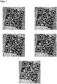
- Figure 2 shows an example of the result of the method to be described now for finding a scanning pattern of scanning points that is adapted to the deformations of a code 12.
- the scanning pattern follows the curvatures and deformations, preferably in that exactly one scanning point is arranged in the center of each code module. This clearly corresponds to a regular grid on a flexible surface that is placed on the code 12 and hugs its unevenness.
- the Figures 3 and 4th show an exemplary process with which this result is achieved.
- the scanning pattern is generated iteratively and locally from the image data starting with a small area in a kind of self-organized, constructive growth.
- Figure 4 an excerpt showing a sub-step of the process in Figure 3 details.
- the Figures 5 to 7 illustrate the process further.
- the image data are captured with code 12 in a step S1.
- These input data are transferred, for example, as image data together with four corner points of a code region (ROI, Region of Interest) recognized in the preprocessing.
- ROI code region
- the number of rows and columns for the scan pattern you are looking for can also be specified. Alternatively, you can determine these parameters yourself.
- a gradient image and a magnitude image of the code region are calculated.
- Figure 5 shows an example of this. Clockwise from the top left, the output image of the code region, the magnitude image, the gradient image in the X direction and the gradient image in the Y direction are displayed.
- a small initial scanning pattern is generated. This preferably applies to the area of a finder pattern.
- finder patterns are the three rectangles arranged one inside the other at the corners.
- a finder pattern consists of 7x7 code modules, so that a 7x7 scanning pattern is suitable for this. Since there is no information about the curvature of the code 12 in the area of the finder pattern, the initial scanning pattern is still regular.
- the size of the finder pattern also allows an estimate of the module size. If no required number of columns and rows was specified for the scanning pattern in step S1, this can be determined on the basis of the module size and the distance between the finder patterns.
- a step S4 the previously obtained scanning pattern, that is to say provisionally the initial scanning pattern, is now adapted to the curvatures of the code 12.
- This step is in Figure 4 shown again in detail.
- the aim of the adaptation is clearly to arrange the sampling points centered in the module they represent. In the case of a flat code, this is achieved with a regular grid for all sampling points at the same time.
- the scanning pattern is adapted to the curvature by individual shifts.
- a shift matrix is initialized which contains the respective shifts for the sampling points to be adapted. Initially, the values are zero because no shifts have yet been determined.
- next steps are carried out for several, preferably all, scanning points of the scanning pattern, but are only described as representative of one scanning point.
- a step S42 it is checked whether the respective scanning point is already centered.
- An advantageous criterion for this is a check of the associated value in the magnitude image. If the magnitude assumes a value of zero or very close to zero, the sampling point lies in a local extreme of the brightness. In the end, it is important that all sampling points each represent a module and no edges in between, and less on a mathematically exact geometric adaptation. So should If several points next to each other in the magnitude image assume the value zero, the result does not interfere if a shift is selected that leads to one of these points which does not form the exact center of the code module.
- a shift in the direction of the local extreme or center of their code module is determined in a step S43. That will be in Figure 6 illustrated. Here are enlarged sections of the in Figure 5 The magnitude and gradient images shown are shown in the same arrangement in the vicinity of the code module under consideration.
- a bright circular point indicates the current position of the sampling point, a bright rectangular point the target position at the local extremum.
- the direction of the shift in results from the associated gradient image, so the scanning point follows the greatest increase or decrease in brightness.
- the individual step length of the shift is intentionally chosen to be small so that the scanning point does not leave the code module.
- a step S44 it is checked whether the scanning point would leave the code module due to previous shifts. This could mainly happen through several small steps if several light or dark code modules are next to each other. In any case, there would be no shift to an adjacent code module with complementary brightness because it is in the opposite direction to the gradient. If the code module were to be exited, the search for the local extremum is deemed to have failed for this sampling point, and it is then preferably not shifted at all, but remains in its starting position, since the previous shifts suggest a deterioration rather than an improvement. Otherwise, the search for the local extremum is continued in step S42, where it is first checked whether the last shift already led there and otherwise a further small shifting step is attempted with step S43.
- the shift matrix is filled with values which do not shift some of the sampling points into the local extremum and the remaining part after a failed search.
- the shift matrix is smoothed, in particular with a Gaussian filter. This not only leads to a more uniform grid overall, but also ensures that the sampling points, for which no suitable shift could be determined individually, are also shifted based on their neighborhood.
- step S46 After the shifts in the shift matrix have been applied to the previous scanning pattern, a check is now made in a step S46 to determine whether any significant shifts beyond a minimum threshold are still being effected. If that is no longer the case and the sampling points are no longer moved, convergence is assumed and the adaptation is ended in a step S47. Otherwise, the shift is repeated iteratively in step S41. As an alternative termination criterion, a maximum number of iterations including only one iteration can be specified.
- the adaptation step S4 is thus completed. It is now checked in a step S5 whether the adapted scanning pattern already covers the code.
- the required size of the scanning pattern was specified in step S1 or determined itself on the basis of estimates such as the module size or position and distance from the finder pattern.
- the sampling pattern is iteratively expanded in a step S6 and the adaptation is repeated from step S4 for the entire sampling pattern, for the newly added sampling points or for the newly added sampling points and some older sampling points, in particular from the vicinity of the expansion .
- Figure 7 illustrates how the scan pattern grows with the iterations according to step S6.
- the initial situation is shown at the top left in which only the finder pattern is captured by the scanning pattern.
- a row and column are added after the first and second iteration, respectively.
- the expansion takes place, for example, initially by adding sampling points spaced apart from the estimated module size.
- An adaptation to the curvature only takes place through step S4 carried out thereafter.
- step S7 An attempt is now made in a step S7 to read the code 12 with the image data at the scanning points of the adapted scanning pattern. If successful, the goal is achieved. Otherwise further decoders can be tried. In the case of a QR code with several finder patterns, the entire process can be repeated with a different finder pattern. Such additional attempts are particularly helpful in the case of severe deformations in order to increase the reading rate even further.
- 2D code types use different finder patterns.
- the L pattern can grow from one or both edges.
- a Maxi or Aztec code each has a central finder pattern that can serve as a starting point. If, as in these examples, there is only one finder pattern, several attempts are nevertheless conceivable to form a scanning pattern. For this purpose, another region that is not a finder pattern is used as the start region, in particular one in which the code modules have already been reliably recognized, be it from previous reading attempts or because the code 12 is largely flat there.
- a first reading attempt can be made at the very beginning before adapting a scanning pattern. It may be possible to read the code 12, especially if the specific code 12 to be processed is little or not at all distorted.
Landscapes
- Engineering & Computer Science (AREA)
- Physics & Mathematics (AREA)
- Electromagnetism (AREA)
- Computer Vision & Pattern Recognition (AREA)
- Theoretical Computer Science (AREA)
- General Physics & Mathematics (AREA)
- Health & Medical Sciences (AREA)
- Artificial Intelligence (AREA)
- Toxicology (AREA)
- General Health & Medical Sciences (AREA)
- Quality & Reliability (AREA)
- Image Processing (AREA)
- Length Measuring Devices By Optical Means (AREA)
- Character Input (AREA)
Abstract
Es wird ein Verfahren zum Lesen von optischen Codes (12) mit Verzerrungen durch einen unebenen Untergrund des Codes (12) angegeben, wobei Bilddaten mit dem Code (12) aufgenommen werden, in den Bilddaten ein Bereich mit dem Code (12) aufgefunden und daraus der Codeinhalt des Codes (12) gelesen wird. Dabei wird der Code (12) aus Bilddaten an Abtastpunkten gelesen, die in einem Abtastmuster entsprechend den Verzerrungen angeordnet sind.A method is specified for reading optical codes (12) with distortions due to an uneven background of the code (12), image data with the code (12) being recorded, an area with the code (12) being found in the image data and from there the code content of the code (12) is read. The code (12) is read from image data at scanning points which are arranged in a scanning pattern in accordance with the distortions.
Description
Die Erfindung betrifft ein Verfahren und eine Codelesevorrichtung zum Lesen von optischen Codes, insbesondere 2D-Codes, mit Verzerrungen durch einen unebenen Untergrund des Codes nach dem Oberbegriff von Anspruch 1 beziehungsweise 14.The invention relates to a method and a code reading device for reading optical codes, in particular 2D codes, with distortions due to an uneven background of the code according to the preamble of
Codeleser sind von Supermarktkassen, zur automatischen Paketidentifikation, Sortierung von Postsendungen, von der Gepäckabfertigung in Flughäfen und aus anderen Logistikanwendungen bekannt. In einem Codescanner wird ein Lesestrahl mittels eines Drehspiegels oder eines Polygonspiegelrads quer über den Code geführt. Ein kamerabasierter Codeleser nimmt mittels eines Bildsensors Bilder der Objekte mit den darauf befindlichen Codes auf, und eine Bildauswertungssoftware extrahiert aus diesen Bildern die Codeinformation. Kamerabasierte Codeleser kommen problemlos auch mit anderen Codearten als eindimensionalen Strichcodes zurecht, die wie ein Matrixcode auch zweidimensional aufgebaut sind und mehr Informationen zur Verfügung stellen.Code readers are known from supermarket checkouts, for automatic parcel identification, sorting of mail, baggage handling in airports and other logistics applications. In a code scanner, a reading beam is guided across the code by means of a rotating mirror or a polygon mirror wheel. A camera-based code reader uses an image sensor to record images of the objects with the codes on them, and image evaluation software extracts the code information from these images. Camera-based code readers can also easily cope with other types of code than one-dimensional barcodes, which, like a matrix code, are also structured two-dimensionally and provide more information.
In einer wichtigen Anwendungsgruppe werden die Code tragenden Objekte an dem Codeleser vorbei gefördert. Ein Codescanner erfasst dabei die jeweils nacheinander in seinen Lesebereich geführten Codes. Alternativ liest in einem kamerabasierten Codeleser eine Zeilenkamera die Objektbilder mit den Codeinformationen sukzessive und zeilenweise mit der Relativbewegung ein. Mit einem zweidimensionalen Bildsensor werden regelmäßig Bilddaten aufgenommen, die sich je nach Aufnahmefrequenz und Fördergeschwindigkeit mehr oder weniger überlappen. Damit die Objekte in beliebiger Orientierung auf dem Förderer angeordnet werden können, sind oft mehrere Codeleser an einem Lesetunnel vorgesehen, um Objekte von mehreren oder allen Seiten aufzunehmen. Ebenso bekannt ist, die Lesefelder von mehreren Codelesern zu kombinieren, um beispielsweise ein breiteres Förderband abzudecken.In an important group of applications, the code-carrying objects are conveyed past the code reader. A code scanner records the codes that are fed into its reading area one after the other. Alternatively, a line camera reads in the object images with the code information successively and line by line with the relative movement in a camera-based code reader. A two-dimensional image sensor is used to regularly record image data that more or less overlap depending on the recording frequency and conveying speed. So that the objects can be arranged in any orientation on the conveyor, several code readers are often provided on a reading tunnel in order to pick up objects from several or all sides. It is also known to combine the reading fields of several code readers, for example to cover a wider conveyor belt.
Es kommt immer wieder vor, dass die Codes nur verzerrt aufgenommen werden. Eine Ursache dafür ist die Anbringung auf nicht planaren Oberflächen. Das kann Knicke, Wölbungen und letztlich völlig zufällige geometrische Verzerrungen zur Folge haben. Dieses Problem tritt unabhängig von der Art auf, wie die Codes erzeugt sind, sei es durch Aufdruck, Einprägen von Codemarkierungen, Aufkleben von Codeetiketten oder eine andere Weise.It happens again and again that the codes are recorded in a distorted manner. One reason for this is attachment to non-planar surfaces. This can lead to kinks, bulges and ultimately completely random geometric distortions. This problem occurs regardless of the way in which the codes are generated, whether by printing, embossing code markings, sticking code labels on or in any other way.
Nun sind in den verschiedenen 2D-Codespezifikationen Fehlerkorrekturmechanismen eingebaut. Sie sind aber nicht so aufgebaut, dass komplexe Deformationen detektierbar wären, sondern implizit wird ein allenfalls geringer Einfluss einer nicht planaren Oberfläche vorausgesetzt. Es gibt jedoch Anwendungen, in denen diese stille Voraussetzung nicht nur im Einzelfall nicht erfüllt ist. Ein typisches Beispiel sind Codes auf weichen Verpackungen wie Plastikhüllen. Dann kommen die vorgesehenen Mechanismen, wie eine Reed-Solomon-Fehlerkorrektur, schnell an ihre Grenzen, und ab einer gewissen Verformung sind die 2D-Codes nicht mehr lesbar.Error correction mechanisms are now built into the various 2D code specifications. However, they are not structured in such a way that complex deformations can be detected, but implicitly a minimal influence of a non-planar surface is assumed. However, there are applications in which this silent requirement is not met, and not just in individual cases. A typical example are codes on soft packaging such as plastic sleeves. Then the intended mechanisms, such as Reed-Solomon error correction, quickly reach their limits, and after a certain deformation, the 2D codes can no longer be read.
Im Stand der Technik wird zum Teil versucht, das aufgenommene Bild des Codes vor dem eigentlichen Codelesen zu entzerren. Das betrifft dann jedoch nicht den konkreten Code und dessen Untergrund, wie bei einer Korrektur von Abbildungsfehlern des Codelesers oder einer Umrechnung der Aufnahmeperspektive. Die
Ein weiterer herkömmlicher Ansatz besteht darin, die geometrische Struktur eines zu lesenden Codes global zu erfassen, etwa anhand einer konvexen Hülle. In manchen Fällen geringer und vor allem regelmäßiger Verzerrungen ist das eine Möglichkeit, aber beispielsweise bei einer verknitterten Plastikhülle als Untergrund enthält die globale Geometrie einfach zu wenig Information, und das Lesen des Codes scheitert weiterhin.Another conventional approach is to capture the geometric structure of a code to be read globally, for example using a convex envelope. In some cases, minor and, above all, regular distortions, this is a possibility, but if, for example, a wrinkled plastic cover is used as the substrate, the global geometry simply contains too little information and reading the code continues to fail.
Es ist daher Aufgabe der Erfindung, ein verbessertes Verfahren zum Lesen eines verzerrten optischen Codes anzugeben.It is therefore the object of the invention to specify an improved method for reading a distorted optical code.
Diese Aufgabe wird durch ein Verfahren und eine Codelesevorrichtung zum Lesen von optischen Codes mit Verzerrungen durch einen unebenen Untergrund des Codes nach Anspruch 1 beziehungsweise 14 gelöst. Die Codes sind durch ihren nicht planen, gekrümmten oder deformierten Untergrund, durch Knicke, Wölbungen oder sonstige geometrische Eigenschaften verzerrt und dementsprechend zunächst schwerer oder gar nicht lesbar. Der optische Code ist insbesondere ein zweidimensionaler Code nach einem der diversen bekannten Standards. Es werden Bilddaten erzeugt, die den Code enthalten und vorzugsweise zumindest grob segmentiert und damit auf den Codebereich zugeschnitten sind. Bilddaten werden typischerweise mit einem Bildsensor eines kamerabasierten Codelesers aufgenommen, wobei prinzipiell auch ein Codescanner zeilenweise ein Intensitätsprofil erfassen und auf diese Weise Bilddaten erzeugen kann. Der Code wird mit einem an sich bekannten Decodierverfahren gelesen.This object is achieved by a method and a code reading device for reading optical codes with distortions due to an uneven background of the code according to
Die Erfindung geht von dem Grundgedanken aus, vor dem eigentlichen Codelesen ein Abtastmuster oder Abtastgitter aus Abtastpunkten zu erzeugen, das sich den Verformungen des Untergrundes des Codes anpasst. Die Bilddaten an diesen Abtastpunkten werden dann für das Codelesen verwendet. Das Abtastmuster ist folglich kein regelmäßiges Gitter, sondern zumindest näherungsweise ebenso verzerrt wie der Code selbst.The invention is based on the basic idea of generating a scanning pattern or scanning grid from scanning points before the actual code reading, which pattern adapts to the deformations of the code's background. The image data at these sampling points are then used for code reading. The scanning pattern is consequently not a regular grid, but at least approximately as distorted as the code itself.
Die Erfindung hat den Vorteil, dass das Abtastmuster die Deformation abbildet und dadurch kompensiert. Der Code kann dann selbst bei starker und unregelmäßiger Deformation noch gelesen und damit die Leserate erhöht werden. Natürlich gibt es Grenzen, etwa wenn Codes derart gefaltet sind, dass ganze Bereiche verdeckt werden. Das Vorgehen funktioniert bei verschiedensten Codearten. Selbst bei anspruchsvollen Anwendungen, wie Folienverpackungen, wird damit eine hohe Leserate erreicht.The invention has the advantage that the scanning pattern maps the deformation and thereby compensates for it. The code can then still be read even with severe and irregular deformation, thus increasing the reading rate. Of course there are limits, for example when codes are folded in such a way that entire areas are covered. The procedure works for a wide variety of code types. A high reading rate is achieved even in demanding applications such as film packaging.
Das Abtastmuster wird vorzugsweise ohne Kenntnis der Krümmung des unebenen Untergrundes bestimmt. Es stehen außer den Bilddaten keine weiteren Informationen zur Verfügung, insbesondere keine dreidimensionale Konturvermessung. Die zu korrigierende Geometrie ist vorab unbekannt und wird auch während des Verfahrens nicht bestimmt. Vielmehr passt sich das Abtastmuster lokal an den verzerrten Code an.The scanning pattern is preferably determined without knowledge of the curvature of the uneven ground. Apart from the image data, no further information is available, in particular no three-dimensional contour measurement. The geometry to be corrected is unknown beforehand and is not determined during the process. Rather, the scanning pattern adapts locally to the distorted code.
Vorzugsweise wird eine Modulgröße des Codes und/oder eine Größe des benötigten Abtastmusters aus einem Finder Pattern bestimmt. Ein Finder Pattern ist ein Teil eines 2D-Codes mit einem spezifischen Muster, an dem der 2D-Code und bestimmte Eigenschaften davon erkannt werden. Es ist daher aus der Codespezifikation bekannt, welche Codeelemente oder Module das Finder Pattern aufweist, und so kann auf die Modulgröße in dem konkret aufgenommenen Code geschlossen werden. Durch Hochrechnen auf den erfassten Codebereich lässt sich weiterhin ableiten, wie viele Abtastpunkte das Abtastmuster insgesamt umfassen muss, um den Code zu überdecken. Bei einem QR-Code steht dafür zusätzlich der Abstand zwischen den Finder Pattern, bei einem DataMatrix-Code die Länge der hier den Code von zwei Seiten vollständig einrahmenden Finder Pattern zur Verfügung.A module size of the code and / or a size of the required scanning pattern is preferably determined from a finder pattern. A finder pattern is a part of a 2D code with a specific pattern by which the 2D code and certain properties thereof can be recognized. It is therefore known from the code specification which code elements or modules the finder pattern has, and it is thus possible to infer the module size in the specifically recorded code. By extrapolating to the captured code area, it is also possible to derive how many scanning points the scanning pattern must encompass in total in order to cover the code. With a QR code, the distance between the finder patterns is also available, with a data matrix code the length of the finder pattern that completely frames the code from two sides.
Das Abtastmuster weist vorzugsweise einen Abtastpunkt je Modul des Codes auf. Mindestens ein Abtastpunkt sollte vorhanden sein, da sonst einige Moduln überhaupt nicht repräsentiert werden. Es reicht aber umgekehrt auch ein Abtastpunkt aus, denn jedes Modul trägt abgesehen von seine 2D-Lage nur die Hell-Dunkel-Information in sich, die durch einen repräsentativ platzierten Abtastpunkt vollumfänglich erfasst ist. Ein Abtastmuster mit mindestens einem Abtastpunkt je Modul ist daher ausreichend, ein Abtastmuster mit genau einem Abtastpunkt sogar eine optimale, immer noch vollständige Konfiguration ohne unnötigen Aufwand.The scanning pattern preferably has one scanning point per module of the code. At least one sampling point should be available, otherwise some modules will not be represented at all. Conversely, however, one scanning point is also sufficient because, apart from its 2D position, each module only contains the light-dark information that is fully recorded by a representatively positioned scanning point. A scanning pattern with at least one scanning point per module is therefore sufficient, and a scanning pattern with exactly one scanning point is even an optimal, still complete configuration without unnecessary effort.
Das Abtastmuster wird vorzugsweise iterativ von einem Finder Pattern ausgehend vergrößert, bis es den Code überdeckt. Das Finder Pattern lässt sich verlässlich lokalisieren. Von diesem anfänglichen kleinen Abtastmuster wird dann das gesamte Abtastmuster durch schrittweise Vergrößerung aufgebaut ("Grid Growing").The scanning pattern is preferably enlarged iteratively starting from a finder pattern until it covers the code. The finder pattern can be reliably localized. From this initially small scanning pattern, the entire scanning pattern is then built up by incremental enlargement ("grid growing").
Vorzugsweise werden anfänglich Abtastpunkte des Abtastmusters für das Finder Pattern festgelegt, insbesondere noch in regelmäßiger Anordnung entsprechend einem planen Untergrund. Dank seines spezifizierten Aufbaus ist für das Finder Pattern bekannt, welche Moduln es enthält. Daher kann hier ein Anfang des Abtastmusters besonders verlässlich gesetzt und angepasst werden. Beispielsweise umfasst ein Finder Pattern eines QR-Codes 7x7 Moduln aus ineinander angeordneten Rechtecken. Dementsprechend kann mit einem Abtastmuster aus 7x7 Abtastpunkten begonnen werden. Bei der Initialisierung wird vorzugsweise zunächst ein regelmäßiges Abtastmuster verwendet, da vorab keinerlei Informationen über die Verzerrungen bekannt sind.Sampling points of the sampling pattern for the finder pattern are preferably initially established, in particular in a regular arrangement corresponding to a flat surface. Thanks to its specified structure, the finder pattern knows which modules it contains. A start of the scanning pattern can therefore be set and adapted particularly reliably here. For example, a finder pattern of a QR code comprises 7x7 modules of rectangles arranged one inside the other. Accordingly, a sampling pattern of 7x7 sampling points can be started. During the initialization, a regular scanning pattern is preferably used first, since no information about the distortions is known beforehand.
Vorteilhafterweise werden die Abtastpunkte jeweils ins Zentrum des von ihnen repräsentierten Moduls verschoben. Bei einem nicht verzerrten, ebenen Code wäre das mit einem regelmäßigen Abtastmuster mit konstantem Abstand zwischen den Abtastpunkten entsprechend der geschätzten Modulgröße sehr einfach durch eine allgemeine Zentrierung zu realisieren. Für die Anpassung an unebene Untergründe werden die Abtastpunkte individuell verschoben, um die jeweilige lokale Verzerrung auszugleichen. Das Zentrum muss keineswegs der exakte geometrische Schwerpunkt eines Moduls sein, es geht nur darum, die Kanten zwischen den Moduln verlässlich zu meiden, damit der Abtastpunkt einen für das Modul repräsentativen Helligkeitswert erfasst.The sampling points are advantageously each shifted to the center of the module they represent. In the case of an undistorted, flat code, this would be very easy to implement by general centering with a regular scanning pattern with a constant distance between the scanning points in accordance with the estimated module size. For adaptation to uneven surfaces, the sampling points are shifted individually in order to compensate for the respective local distortion. The center does not have to be the exact geometric center of gravity of a module, it is just a matter of reliably avoiding the edges between the modules so that the scanning point detects a brightness value that is representative of the module.
Vorzugsweise wird ein Gradientenbild und ein Magnitudenbild des Codes berechnet, um anhand des Magnitudenbildes festzustellen, ob ein jeweiliger Abtastpunkt in einem lokalen Extremum liegt und die Richtung einer noch erforderlichen Verschiebung aus dem Gradientenbild zu bestimmen. Konkret kann ein Bild für die Magnitude und jeweils ein Bild für den Gradienten in X- und Y-Richtung bestimmt werden. Der Gradient, der ja ein Vektor ist, wird folglich in seine Richtungen und seinen Betrag zerlegt. In diesem Zusammenhang ist Bild ein Begriff für eine beliebige Repräsentation des Gradienten. Es genügt, diese Gradientenberechnung ein einziges Mal für die Bilddaten des Codebereichs durchzuführen, das Ergebnis kann dann in sämtlichen Iterationen und für alle Abtastpunkte verwendet werden. Ein Abtastpunkt wird als hinreichend in seinem Modul zentriert angesehen, wenn die Magnitude ein lokales Extremum anzeigt, mit anderen Worten zumindest nahe bei Null liegt. Das ist eine mathematische Formulierung dessen, dass der Abtastpunkt hinreichend weit von Kanten zwischen den Moduln entfernt ist und damit sozusagen mitten in dem hellen beziehungsweise dunklen Bereich des Moduls liegt. Das Gradientenbild zeigt die Richtung an, in welcher das lokale Extremum liegt, wenn die Magnitudenbedingung noch nicht erfüllt ist.A gradient image and a magnitude image of the code are preferably calculated in order to determine on the basis of the magnitude image whether a respective scanning point lies in a local extremum and to determine the direction of a displacement that is still required from the gradient image. Specifically, one image for the magnitude and one image each for the gradient in the X and Y directions can be determined. The gradient, which is a vector, is consequently broken down into its directions and its magnitude. In this context, image is a term for any representation of the gradient. It is sufficient to carry out this gradient calculation once for the image data of the code area; the result can then be used in all iterations and for all sampling points. A sampling point is considered to be sufficiently centered in its module if the magnitude indicates a local extreme, in other words is at least close to zero. This is a mathematical formulation of the fact that the scanning point is sufficiently far away from the edges between the modules and is thus, so to speak, in the middle of the light or dark area of the module. The gradient image shows the direction in which the local extreme lies if the magnitude condition is not yet met.
Eine Verschiebung wird vorzugsweise in Schritten kleiner als die Modulgröße versucht, bis ein lokales Extremum erreicht ist, die Verschiebung aus dem Modul herausführen würde oder eine Maximalzahl von Schritten versucht wurde, wobei insbesondere keine Verschiebung des jeweiligen Abtastpunktes erfolgt, wenn kein lokales Extremum gefunden werden konnte. Dabei wird das lokale Extremum durch ein iteratives Verfahren gesucht. Die Schrittgröße ist klein gewählt, damit kein falsches lokales Extremum in einem anderen Modul gefunden wird, was sonst insbesondere bei mehreren benachbarten hellen beziehungsweise dunklen Moduln passieren könnte. Führt eine Verschiebung weiter als die geschätzte Modulgröße, so wird abgebrochen. Es wird dann vorzugweise nicht mit der bisher bestimmten Verschiebung weitergearbeitet, die vermutlich kein sinnvolles Ergebnis darstellt, sondern dieser Abtastpunkt vorerst gar nicht verschoben.A shift is preferably attempted in steps smaller than the module size until a local extremum is reached, the shift would lead out of the module or a maximum number of steps was attempted, in particular there is no shift of the respective sampling point if no local extremum could be found . The local extreme is searched for using an iterative process. The step size is selected to be small so that no wrong local extremum is found in another module, which could otherwise happen in particular with several neighboring light or dark modules. If a shift results in more than the estimated module size, it is aborted. It will then preferably not continued working with the shift determined up to now, which presumably does not represent a meaningful result, but rather this sampling point has not shifted at all for the time being.
Vorteilhafterweise wird eine Verschiebematrix von Verschiebungen der jeweiligen Abtastpunkte in ein lokales Extremum geglättet, insbesondere mit einem Gaussfilter. Es werden also Verschiebungen für die einzelnen Abtastpunkte bestimmt und in die Verschiebematrix geschrieben. Wie soeben erläutert, wird für manche Abtastpunkte keine geeignete Verschiebung gefunden, und sie verbleiben in ihrer Ausgangsposition. Durch das Glätten der Verschiebematrix werden also nicht nur die gefundenen Verschiebungen einem gewissen gegenseitigen Ausgleich unterworfen, sondern auch diejenigen Abtastpunkte über ihre Nachbarn angepasst, die sonst in ihrer Ausgangsposition verblieben wären.A shift matrix of shifts of the respective sampling points is advantageously smoothed into a local extreme, in particular with a Gaussian filter. Shifts are therefore determined for the individual sampling points and written into the shift matrix. As just explained, for some sample points no suitable shift is found and they remain in their starting position. By smoothing the displacement matrix, not only are the displacements found subject to a certain mutual compensation, but also those sampling points via their neighbors that would otherwise have remained in their starting position are adapted.
Vorzugsweise wird iterativ so lange eine neue Verschiebematrix mit Verschiebungen von Abtastpunkten in ein lokales Extremum bestimmt und jeweils auf das Abtastmuster angewandt, bis eine weitere Verschiebematrix keine Verschiebungen oberhalb einer Toleranzschwelle mehr bewirkt oder bis eine maximale Anzahl Iterationen erreicht ist. Die Verschiebungen werden solange wiederholt, bis das Verfahren konvergiert und keine Verbesserungen mehr erreicht werden. Vorsichtshalber sollte noch eine Abbruchbedingung nach einer bestimmten Anzahl von Schritten vorgesehen sein, womit auch eine sonstige von außen vorgegebene Bedingung wie der Ablauf einer maximal zur Verfügung stehende Rechenzeit umfasst sein soll.Preferably, a new shift matrix with shifts of sampling points in a local extreme is determined iteratively and applied to the sampling pattern in each case until a further shift matrix no longer causes shifts above a tolerance threshold or until a maximum number of iterations is reached. The shifts are repeated until the method converges and no further improvements are achieved. As a precaution, a termination condition should also be provided after a certain number of steps, which should also include another externally specified condition such as the expiry of a maximum available computing time.
Das Abtastmuster wird vorzugsweise iterativ an mindestens einem Rand mit zusätzlichen Abtastpunkten vergrößert, bis es den Code überdeckt und/oder eine vorgegebene Größe erreicht. Vorzugsweise wächst das Abtastmuster pro Iteration jeweils um eine Spalte und/oder Zeile. Es ist denkbar, mehrere Zeilen oder Spalten auf einmal hinzuzufügen, aber bei starker Variation der lokalen Krümmung verschlechtert das die Anpassung. Nachdem das Abtastmuster auf diese Weise gewachsen ist, werden die hinzugefügten Abtastpunkte, sämtliche Abtastpunkte oder eine Zwischenmenge, wie die hinzugekommenen Abtastpunkte und deren Nachbarn aus dem schon zuvor bestehenden Abtastmuster, vorzugsweise der beschriebenen Anpassung zum Zentrieren in ihren jeweiligen Moduln unterworfen. Das Wachsen und damit das Verfahren zum Erzeugen des angepassten Abtastmusters ist beendet, wenn der Code überdeckt ist. Das wird insbesondere durch Schätzung der benötigten Größe des Abtastmusters anhand der Größe des Codebereichs und der geschätzten Modulgröße festgestellt.The scanning pattern is preferably enlarged iteratively at at least one edge with additional scanning points until it covers the code and / or reaches a predetermined size. The scanning pattern preferably grows by one column and / or row per iteration. It is conceivable to add several rows or columns at once, but if the local curvature varies greatly, this worsens the adaptation. After the scanning pattern has grown in this way, the added scanning points, all scanning points or an intermediate set, such as the added scanning points and their neighbors from the previously existing scanning pattern, are preferably subjected to the described adaptation for centering in their respective modules. The growth and thus the method for generating the adapted scanning pattern is ended when the code is covered. This is determined in particular by estimating the required size of the scanning pattern on the basis of the size of the code area and the estimated module size.
Wenn mehrere der hier vorgestellten Schritte gemeinsam umgesetzt werden, ist zu beachten, dass es sich um eine mehrfach geschachtelte Iteration handelt. Die übergeordnete Iteration beginnt mit einem kleinen Abtastmuster vorzugsweise bei einem Finder Pattern und lässt dieses sukzessive über den Codebereich anwachsen. Zur jeweiligen Anpassung wird mehrfach iterativ eine Verschiebematrix bestimmt und angewandt. Es kann eine dritte Iterationsebene innerhalb der Bestimmung einer Verschiebematrix hinzukommen, mit der versucht wird, einen jeweiligen Abtastpunkt schrittweise ins Zentrum seines Moduls zu schieben und so einen einzelnen Eintrag in der Verschiebematrix zu erhalten.If several of the steps presented here are implemented together, it should be noted that it is a multiple nested iteration. The higher-level iteration begins with a small sampling pattern, preferably with a finder pattern, and lets this gradually grow over the code area. For the respective adaptation, a shift matrix is determined and applied iteratively several times. A third iteration level can be added within the determination of a shift matrix, with which an attempt is made to shift a respective sampling point step by step into the center of its module and thus obtain a single entry in the shift matrix.
Vorzugsweise wird ein weiteres Abtastmuster von einem anderen Finder Pattern ausgehend bestimmt. Das ist natürlich nur bei Codearten wie dem QR-Code möglich, wo mehrere Finder Pattern vorgesehen sind. Bei anderen Codearten könnte alternativ versucht werden, von einem Bereich aus das Abtastmuster wachsen zu lassen, der zwar kein Finder Pattern ist, dessen Module jedoch in einem früheren Leseversuch oder durch Bildverarbeitung eindeutig erfassbar sind. Dadurch können noch zusätzliche Leseversuche unternommen werden, falls aus irgendeinem Grund das zunächst verwendete Finder Pattern kein günstiger Ausgangspunkt war.A further scanning pattern is preferably determined on the basis of another finder pattern. Of course, this is only possible with code types such as the QR code, where several finder patterns are provided. In the case of other types of code, an attempt could alternatively be made to let the scanning pattern grow from an area that is not a finder pattern, but whose modules can be clearly detected in an earlier reading attempt or by image processing. This means that additional reading attempts can be made if, for whatever reason, the finder pattern used initially was not a good starting point.
Das erfindungsgemäße Verfahren kann auf ähnliche Weise weitergebildet werden und zeigt dabei ähnliche Vorteile. Derartige vorteilhafte Merkmale sind beispielhaft, aber nicht abschließend in den sich an die unabhängigen Ansprüche anschließenden Unteransprüchen beschrieben.The method according to the invention can be developed in a similar way and shows similar advantages. Such advantageous features are described by way of example, but not conclusively, in the subclaims that follow the independent claims.
Die Erfindung wird nachstehend auch hinsichtlich weiterer Merkmale und Vorteile beispielhaft anhand von Ausführungsformen und unter Bezug auf die beigefügte Zeichnung näher erläutert. Die Abbildungen der Zeichnung zeigen in:
- Fig. 1
- eine schematische Darstellung eines Codelesers;
- Fig. 2
- eine Darstellung eines beispielhaften 2D-Codes mit einem an dessen Verzerrungen angepasstem Abtastmuster;
- Fig. 3
- ein Ablaufschema, wie ein angepasstes Abtastmuster iterativ von einem Finder Pattern ausgehend über den gesamten Code wächst;
- Fig. 4
- ein Ablaufschema der Anpassung des Abtastmusters innerhalb der jeweiligen Iterationen nach
Figur 3 ; - Fig. 5
- eine beispielhafte Darstellung von Magnitudenbild und Gradientenbild zu einem Codebereich;
- Fig. 6
- eine Vergrößerung zu
Figur 6 zu einzelnen Codemoduln; und - Fig. 7
- eine beispielhafte Darstellung von anwachsenden Abtastmustern nach verschiedenen Iterationen des Ablaufs gemäß
Figur 3 .
- Fig. 1
- a schematic representation of a code reader;
- Fig. 2
- a representation of an exemplary 2D code with a scanning pattern adapted to its distortions;
- Fig. 3
- a flow chart of how an adapted sampling pattern grows iteratively over the entire code, starting from a finder pattern;
- Fig. 4
- a flow chart of the adaptation of the scanning pattern within the respective iterations according to
Figure 3 ; - Fig. 5
- an exemplary representation of magnitude image and gradient image for a code area;
- Fig. 6
- an enlargement too
Figure 6 to individual code modules; and - Fig. 7
- an exemplary representation of increasing sampling patterns after different iterations of the sequence according to FIG
Figure 3 .
Ziel der Bildverarbeitung der Steuer- und Auswertungseinheit 16 ist, Codebereiche zu erkennen und die dort angebrachten Codes 12 auszulesen. Die Erfindung befasst sich mit einem Teilschritt, mit dem ein Abtastmuster von Abtastpunkten erzeugt wird, das sich an die Verzerrungen des Codes 12 anpasst, die durch Abweichungen von einem ebenen Untergrund entstehen. Das Verfahren, um ein solches Abtastmuster zu erzeugen, wird später unter Bezugnahme auf die
Über eine Schnittstelle 18 gibt der Codeleser 10 Informationen aus, wie gelesene Codes oder Bilddaten. Es ist auch denkbar, dass die Steuer- und Auswertungseinheit 16 nicht in dem eigentlichen Codeleser 10 angeordnet ist, sondern als eigenes Steuerungsgerät an einen oder mehrere Codeleser 10 angeschlossen wird. Dann dient die Schnittstelle 18 auch als Verbindung zwischen interner und externer Steuerung und Auswertung. Die Steuer- und Auswertungsfunktionalität 16 kann praktisch beliebig auf interne und externe Bausteine verteilt werden, wobei die externen Bausteine auch über Netzwerk oder Cloud angeschlossen sein können. Das alles wird hier nicht weiter unterschieden und die Steuer- und Auswertungseinheit 16 unabhängig von der konkreten Implementierung als Teil des Codelesers 10 aufgefasst.The
Die jeweils gezeigten Beispiele von Codes 12 sind QR-Codes. Die Erfindung ist aber darauf nicht beschränkt, sondern auch für andere 2D-Codes anwendbar, wie etwa DataMatrix-Codes, MaxiCodes oder Aztec-Codes. QR-Codes sind in gewisser Weise sogar besonders anspruchsvoll, da sie keine umrahmenden Finder-Pattern aufweisen wie beispielsweise DataMatrix-Codes, die schon gewisse Rückschlüsse auf Deformationen erlauben. Grundsätzlich wären auch Barcodes auf die erfindungsgemäße Weise lesbar. Barcodes sind aber ohnehin schon wesentlich toleranter gegenüber den hier behandelten Verzerrungen, da es genügt, eine einzige Leselinie quer durch den Code zu finden, die noch alle Codemodule schneidet.The examples of
Die
Anfangs werden in einem Schritt S1 die Bilddaten mit dem Code 12 erfasst. Diese Eingabedaten werden beispielsweise als Bilddaten zusammen mit vier Eckpunkten einer in der Vorverarbeitung erkannten Coderegion (ROI, Region of Interest) übergeben. Die Anzahl Zeilen und Spalten für das gesuchte Abtastmuster kann ebenfalls vorgegeben werden. Alternativ werden diese Parameter selbst bestimmt.Initially, the image data are captured with
In einem Schritt S2 werden ein Gradienten- und ein Magnitudenbild der Coderegion berechnet.
In einem Schritt S3 wird ein kleines initiales Abtastmuster erzeugt. Das betrifft vorzugsweise den Bereich eines Finder Patterns. Finder Patterns sind bei den in den Figuren gezeigten beispielhaften Codes 12 die drei ineinander angeordneten Rechtecke an den Ecken. Bei einem QR-Code besteht ein Finder Pattern aus 7x7 Codemoduln, so dass dafür ein 7x7 Abtastpunkte großes Abtastmuster geeignet ist. Da keine Informationen über die Krümmung des Codes 12 im Bereich des Finder Patterns vorliegt, ist das initiale Abtastmuster noch regelmäßig. Die Größe des Finder Patterns erlaubt außerdem eine Abschätzung der Modulgröße. Sofern im Schritt S1 keine benötigte Anzahl an Spalten und Zeilen für das Abtastmuster vorgegeben wurde, kann dies anhand der Modulgröße und des Abstands zwischen den Finder Pattern bestimmt werden.In a step S3 a small initial scanning pattern is generated. This preferably applies to the area of a finder pattern. In the
In einem Schritt S4 wird nun das bisher erhaltene Abtastmuster, vorläufig also das initiale Abtastmuster, an die Krümmungen des Codes 12 angepasst. Dieser Schritt ist in
Zunächst wird in einem Schritt S41 eine Verschiebematrix initalisiert, die jeweilige Verschiebungen für die anzupassenden Abtastpunkte enthält. Anfangs sind die Werte Null, da noch keine Verschiebungen bestimmt wurden.First, in a step S41, a shift matrix is initialized which contains the respective shifts for the sampling points to be adapted. Initially, the values are zero because no shifts have yet been determined.
Die nächsten Schritte werden für mehrere, vorzugsweise alle Abtastpunkte des Abtastmusters durchgeführt, aber nur stellvertretend für einen Abtastpunkt beschrieben. In einem Schritt S42 wird überprüft, ob der jeweilige Abtastpunkt bereits zentriert ist. Ein vorteilhaftes Kriterium dafür ist eine Überprüfung des zugehörigen Werts im Magnitudenbild. Wenn die Magnitude nämlich einen Wert Null oder sehr nahe Null annimmt, liegt der Abtastpunkt in einem lokalen Extremum der Helligkeit. Darauf kommt es am Ende an, dass alle Abtastpunkte jeweils ein Modul repräsentieren und keine Kanten dazwischen, weniger auf eine mathematisch exakte geometrische Anpassung. Sollten also mehrere Punkte nebeneinander im Magnitudenbild den Wert Null annehmen, so stört es das Ergebnis nicht, wenn eine Verschiebung gewählt wird, die zu einem dieser Punkte führt, der nicht die exakte Mitte des Codemoduls bildet.The next steps are carried out for several, preferably all, scanning points of the scanning pattern, but are only described as representative of one scanning point. In a step S42 it is checked whether the respective scanning point is already centered. An advantageous criterion for this is a check of the associated value in the magnitude image. If the magnitude assumes a value of zero or very close to zero, the sampling point lies in a local extreme of the brightness. In the end, it is important that all sampling points each represent a module and no edges in between, and less on a mathematically exact geometric adaptation. So should If several points next to each other in the magnitude image assume the value zero, the result does not interfere if a shift is selected that leads to one of these points which does not form the exact center of the code module.
Für noch nicht ausreichend zentrierten Abtastpunkte wird in einem Schritt S43 eine Verschiebung in Richtung lokales Extremum oder Zentrum ihres Codemoduls bestimmt. Das wird in
In einem Schritt S44 wird geprüft, ob der Abtastpunkt durch bisherige Verschiebungen das Codemodul verlassen würde. Das könnte vor allem durch mehrere kleine Schritte passieren, wenn mehrere helle oder dunkle Codemodule nebeneinanderliegen. In ein benachbartes Codemodul mit komplementärer Helligkeit würde ohnehin nicht verschoben, weil das in Gegenrichtung zum Gradienten liegt. Würde das Codemodul verlassen, so gilt für diesen Abtastpunkt die Suche nach dem lokalen Extremum als gescheitert, und vorzugsweise wird er dann gar nicht verschoben, sondern bleibt in seiner Ausgangsposition, da die bisherigen Verschiebungen eher eine Verschlechterung als eine Verbesserung erwarten lassen. Andernfalls wird die Suche nach dem lokalen Extremum im Schritt S42 fortgesetzt, wo zunächst geprüft wird, ob die letzte Verschiebung schon dorthin führte und ansonsten mit Schritt S43 ein weiterer kleiner Verschiebungsschritt versucht wird.In a step S44 it is checked whether the scanning point would leave the code module due to previous shifts. This could mainly happen through several small steps if several light or dark code modules are next to each other. In any case, there would be no shift to an adjacent code module with complementary brightness because it is in the opposite direction to the gradient. If the code module were to be exited, the search for the local extremum is deemed to have failed for this sampling point, and it is then preferably not shifted at all, but remains in its starting position, since the previous shifts suggest a deterioration rather than an improvement. Otherwise, the search for the local extremum is continued in step S42, where it is first checked whether the last shift already led there and otherwise a further small shifting step is attempted with step S43.
Ist die Schleife der Schritte S42 bis S44 für alle Abtastpunkte beendet, so ist die Verschiebematrix mit Werten besetzt, die einen Teil der Abtastpunkte in das lokale Extremum und den übrigen Teil nach gescheiterter Suche gar nicht verschiebt. In einem Schritt S45 wird die Verschiebematrix geglättet, insbesondere mit einem Gaussfilter. Das führt nicht nur zu einem insgesamt gleichmäßigeren Gitter, sondern sorgt auch dafür, dass die Abtastpunkte, für die individuell keine geeignete Verschiebung bestimmt werden konnte, anhand ihrer Nachbarschaft doch mit verschoben werden.If the loop of steps S42 to S44 has ended for all sampling points, the shift matrix is filled with values which do not shift some of the sampling points into the local extremum and the remaining part after a failed search. In a step S45, the shift matrix is smoothed, in particular with a Gaussian filter. This not only leads to a more uniform grid overall, but also ensures that the sampling points, for which no suitable shift could be determined individually, are also shifted based on their neighborhood.
Nachdem die Verschiebungen der Verschiebematrix auf das bisherige Abtastmuster angewandt sind, wird nun in einem Schritt S46 wird geprüft, ob überhaupt noch nennenswerte Verschiebungen jenseits einer Minimalschwelle bewirkt werden. Wenn das nämlich nicht mehr der Fall ist und die Abtastpunkte nicht mehr bewegt werden, wird ein Konvergieren angenommen und die Anpassung in einem Schritt S47 beendet. Ansonsten wird die Verschiebung iterativ im Schritt S41 wiederholt. Als alternatives Abbruchkriterium kann eine Höchstzahl Iterationen einschließlich nur einer Iteration vorgegeben werden.After the shifts in the shift matrix have been applied to the previous scanning pattern, a check is now made in a step S46 to determine whether any significant shifts beyond a minimum threshold are still being effected. If that is no longer the case and the sampling points are no longer moved, convergence is assumed and the adaptation is ended in a step S47. Otherwise, the shift is repeated iteratively in step S41. As an alternative termination criterion, a maximum number of iterations including only one iteration can be specified.
Zurück zu
In der Mitte rechts von
Mit den Bilddaten an den Abtastpunkten des angepassten Abtastmusters wird nun in einem Schritt S7 versucht, den Code 12 zu lesen. Bei Erfolg ist das Ziel erreicht. Andernfalls können weitere Decoder versucht werden. Bei einem QR-Code mit mehreren Finder Pattern kann das gesamte Verfahren mit einem anderen Finder Pattern wiederholt werden. Solche zusätzlichen Versuche sind vor allem bei starken Verformungen hilfreich, um die Leserate nochmals zu steigern.An attempt is now made in a step S7 to read the
Andere 2D-Codearten nutzen andere Finder Pattern. Bei einem DataMatrix-Code kann das L-Muster von einer oder beiden Kanten ausgehend anwachsen. Ein Maxi- oder Aztec-Code weist jeweils ein zentrales Finder Pattern auf, das als Ausgangspunkt dienen kann. Gibt es wie in diesen Beispielen nur ein Finder Pattern, so sind dennoch mehrere Versuche denkbar, ein Abtastmuster zu bilden. Dafür wird eine andere Region, die kein Finder Pattern ist, als Startregion verwendet, insbesondere eine solche, in der die Codemodule schon zuverlässig erkannt sind, sei es aus früheren Leseversuchen oder weil der Code 12 dort weitgehend eben ist.Other 2D code types use different finder patterns. In the case of a data matrix code, the L pattern can grow from one or both edges. A Maxi or Aztec code each has a central finder pattern that can serve as a starting point. If, as in these examples, there is only one finder pattern, several attempts are nevertheless conceivable to form a scanning pattern. For this purpose, another region that is not a finder pattern is used as the start region, in particular one in which the code modules have already been reliably recognized, be it from previous reading attempts or because the
Es sei noch darauf hingewiesen, dass auch schon ganz am Anfang vor Anpassung eines Abtastmusters ein erster Leseversuch unternommen werden kann. Womöglich gelingt es dabei schon, den Code 12 zu lesen, insbesondere wenn der konkret zu bearbeitende Code 12 wenig oder gar nicht verzerrt ist.It should also be pointed out that a first reading attempt can be made at the very beginning before adapting a scanning pattern. It may be possible to read the
Claims (14)
dadurch gekennzeichnet,
dass der Code (12) aus Bilddaten an Abtastpunkten gelesen wird, die in einem Abtastmuster entsprechend den Verzerrungen angeordnet sind.Method for reading optical codes (12), in particular 2D codes, with distortions due to an uneven background of the code (12), image data with the code (12) being recorded, an area with the code (12) being found in the image data and the code content of the code (12) is read therefrom,
characterized,
that the code (12) is read from image data at sampling points which are arranged in a sampling pattern corresponding to the distortions.
wobei das Abtastmuster ohne Kenntnis der Krümmung des unebenen Untergrundes bestimmt wird.Method according to claim 1,
wherein the scanning pattern is determined without knowledge of the curvature of the uneven ground.
wobei eine Modulgröße des Codes (12) und/oder eine Größe des benötigten Abtastmusters aus einem Finder Pattern bestimmt wird.Method according to claim 1 or 2,
wherein a module size of the code (12) and / or a size of the required scanning pattern is determined from a finder pattern.
wobei das Abtastmuster einen Abtastpunkt je Modul des Codes (12) aufweist.Method according to one of the preceding claims,
wherein the scanning pattern has one scanning point per module of the code (12).
wobei das Abtastmuster iterativ von einem Finder Pattern ausgehend vergrößert wird, bis es den Code (12) überdeckt.Method according to one of the preceding claims,
wherein the scanning pattern is iteratively enlarged starting from a finder pattern until it covers the code (12).
wobei anfänglich Abtastpunkte des Abtastmusters für das Finder Pattern festgelegt werden, insbesondere noch in regelmäßiger Anordnung entsprechend einem planen Untergrund.Method according to one of the preceding claims,
initially, scanning points of the scanning pattern for the finder pattern are defined, in particular still in a regular arrangement corresponding to a flat surface.
wobei die Abtastpunkte jeweils ins Zentrum des von ihnen repräsentierten Moduls verschoben werden.Method according to one of the preceding claims,
whereby the sampling points are each shifted to the center of the module they represent.
wobei ein Gradientenbild und ein Magnitudenbild des Codes (12) berechnet wird, um anhand des Magnitudenbildes festzustellen, ob ein jeweiliger Abtastpunkt in einem lokalen Extremum liegt und die Richtung einer noch erforderlichen Verschiebung aus dem Gradientenbild zu bestimmen.Method according to claim 7,
wherein a gradient image and a magnitude image of the code (12) are calculated in order to determine on the basis of the magnitude image whether a respective scanning point lies in a local extreme and to determine the direction of a displacement that is still required from the gradient image.
wobei eine Verschiebung in Schritten kleiner als die Modulgröße versucht wird, bis ein lokales Extremum erreicht ist, die Verschiebung aus dem Modul herausführen würde oder eine Maximalzahl von Schritten versucht wurde, wobei insbesondere keine Verschiebung des jeweiligen Abtastpunktes erfolgt, wenn kein lokales Extremum gefunden werden konnte.Method according to claim 7 or 8,
A shift in steps smaller than the module size is attempted until a local extremum is reached, the shift would lead out of the module or a maximum number of steps was attempted, in particular no shift of the respective sampling point takes place if no local extremum could be found .
wobei eine Verschiebematrix von Verschiebungen der jeweiligen Abtastpunkte in ein lokales Extremum geglättet wird, insbesondere mit einem Gaussfilter.Method according to one of Claims 7 to 9,
wherein a shift matrix of shifts of the respective sampling points is smoothed into a local extreme, in particular with a Gaussian filter.
wobei iterativ so lange eine neue Verschiebematrix mit Verschiebungen von Abtastpunkten in ein lokales Extremum bestimmt und jeweils auf das Abtastmuster angewandt wird, bis eine weitere Verschiebematrix keine Verschiebungen oberhalb einer Toleranzschwelle mehr bewirkt oder bis eine maximale Anzahl Iterationen erreicht ist.Method according to one of Claims 7 to 10,
a new shift matrix with shifts of sampling points in a local extreme is determined iteratively and applied to the sampling pattern in each case until a further shift matrix no longer causes shifts above a tolerance threshold or until a maximum number of iterations is reached.
wobei das Abtastmuster iterativ an mindestens einem Rand mit zusätzlichen Abtastpunkten vergrößert wird, bis es den Code (12) überdeckt und/oder eine vorgegebene Größe erreicht.Method according to one of the preceding claims,
wherein the scanning pattern is iteratively enlarged on at least one edge with additional scanning points until it covers the code (12) and / or reaches a predetermined size.
wobei ein weiteres Abtastmuster von einem anderen Finder Pattern ausgehend bestimmt wird.Method according to one of the preceding claims,
a further sampling pattern being determined on the basis of another finder pattern.
dadurch gekennzeichnet,
dass die Steuer- und Auswertungseinheit (16) weiterhin dafür ausgebildet ist, den Code (12) aus Bilddaten an Abtastpunkten zu lesen, die in einem Abtastmuster entsprechend den Verzerrungen angeordnet sind.Code reading device (10) for reading optical codes (12), in particular 2D codes, with distortions due to an uneven base of the code (12), the code reading device (10) having an image sensor (14) for recording of image data with the code (12) and a control and evaluation unit (16) which is designed to locate an area with the code (12) in the image data and to read the code content of the code (12) therefrom,
characterized,
that the control and evaluation unit (16) is further designed to read the code (12) from image data at scanning points which are arranged in a scanning pattern corresponding to the distortions.
Priority Applications (6)
| Application Number | Priority Date | Filing Date | Title |
|---|---|---|---|
| DK20153885.7T DK3855342T3 (en) | 2020-01-27 | 2020-01-27 | READING OPTICAL CODES |
| EP20153885.7A EP3855342B1 (en) | 2020-01-27 | 2020-01-27 | Reading of optical codes |
| JP2021009431A JP7191995B2 (en) | 2020-01-27 | 2021-01-25 | Optical code reading |
| KR1020210010456A KR102576619B1 (en) | 2020-01-27 | 2021-01-25 | Reading of optical codes |
| CN202110103384.XA CN113177423A (en) | 2020-01-27 | 2021-01-26 | Reading of optical codes |
| US17/158,296 US11250228B2 (en) | 2020-01-27 | 2021-01-26 | Reading of optical codes |
Applications Claiming Priority (1)
| Application Number | Priority Date | Filing Date | Title |
|---|---|---|---|
| EP20153885.7A EP3855342B1 (en) | 2020-01-27 | 2020-01-27 | Reading of optical codes |
Publications (2)
| Publication Number | Publication Date |
|---|---|
| EP3855342A1 true EP3855342A1 (en) | 2021-07-28 |
| EP3855342B1 EP3855342B1 (en) | 2021-12-15 |
Family
ID=69326432
Family Applications (1)
| Application Number | Title | Priority Date | Filing Date |
|---|---|---|---|
| EP20153885.7A Active EP3855342B1 (en) | 2020-01-27 | 2020-01-27 | Reading of optical codes |
Country Status (6)
| Country | Link |
|---|---|
| US (1) | US11250228B2 (en) |
| EP (1) | EP3855342B1 (en) |
| JP (1) | JP7191995B2 (en) |
| KR (1) | KR102576619B1 (en) |
| CN (1) | CN113177423A (en) |
| DK (1) | DK3855342T3 (en) |
Citations (5)
| Publication number | Priority date | Publication date | Assignee | Title |
|---|---|---|---|---|
| EP0736835A2 (en) * | 1995-04-06 | 1996-10-09 | ROLLS-ROYCE plc | Process and apparatus for reading a dot matrix code marking on an article |
| US7878402B2 (en) | 2005-12-20 | 2011-02-01 | Cognex Technology And Investment Corporation | Decoding distorted symbols |
| US8235296B2 (en) | 2006-06-28 | 2012-08-07 | Keyence Corporation | Method of and system for setting laser processing conditions, laser processing system, computer program for setting laser processing conditions, computer readable medium and recording device on which laser processing conditions are recorded |
| EP2843616A1 (en) | 2013-08-29 | 2015-03-04 | Sick Ag | Optoelectronic device and method for recording rectified images |
| EP3309703A1 (en) * | 2015-07-23 | 2018-04-18 | Fujian Landi Commercial Equipment Co., Ltd | Method and system for decoding qr code based on weighted average grey method |
Family Cites Families (9)
| Publication number | Priority date | Publication date | Assignee | Title |
|---|---|---|---|---|
| JP3458737B2 (en) * | 1998-11-27 | 2003-10-20 | 株式会社デンソー | Reading method of two-dimensional code and recording medium |
| JP3811686B2 (en) | 2003-06-02 | 2006-08-23 | 株式会社日立インフォメーションテクノロジー | Two-dimensional code reader |
| US6814291B1 (en) * | 2003-12-15 | 2004-11-09 | Pitney Bowes Inc. | Robust barcode reader |
| JP2007206738A (en) | 2006-01-30 | 2007-08-16 | Kyocera Corp | Imaging device and method |
| JP4951735B2 (en) | 2007-11-26 | 2012-06-13 | 株式会社デンソーウェーブ | Optical information reader |
| JP2009295113A (en) * | 2008-06-09 | 2009-12-17 | Olympus Corp | Barcode reading device and its reading data processing method |
| FR2979160B1 (en) * | 2011-08-16 | 2013-09-06 | Mobilead | OPTICAL READING CODE PREPARATION DEVICE |
| US10249030B2 (en) * | 2015-10-30 | 2019-04-02 | Hand Held Products, Inc. | Image transformation for indicia reading |
| DK3428835T3 (en) * | 2017-07-13 | 2019-07-01 | Sick Ag | METHOD FOR READING AN OPTICAL CODE |
-
2020
- 2020-01-27 EP EP20153885.7A patent/EP3855342B1/en active Active
- 2020-01-27 DK DK20153885.7T patent/DK3855342T3/en active
-
2021
- 2021-01-25 JP JP2021009431A patent/JP7191995B2/en active Active
- 2021-01-25 KR KR1020210010456A patent/KR102576619B1/en active IP Right Grant
- 2021-01-26 US US17/158,296 patent/US11250228B2/en active Active
- 2021-01-26 CN CN202110103384.XA patent/CN113177423A/en active Pending
Patent Citations (5)
| Publication number | Priority date | Publication date | Assignee | Title |
|---|---|---|---|---|
| EP0736835A2 (en) * | 1995-04-06 | 1996-10-09 | ROLLS-ROYCE plc | Process and apparatus for reading a dot matrix code marking on an article |
| US7878402B2 (en) | 2005-12-20 | 2011-02-01 | Cognex Technology And Investment Corporation | Decoding distorted symbols |
| US8235296B2 (en) | 2006-06-28 | 2012-08-07 | Keyence Corporation | Method of and system for setting laser processing conditions, laser processing system, computer program for setting laser processing conditions, computer readable medium and recording device on which laser processing conditions are recorded |
| EP2843616A1 (en) | 2013-08-29 | 2015-03-04 | Sick Ag | Optoelectronic device and method for recording rectified images |
| EP3309703A1 (en) * | 2015-07-23 | 2018-04-18 | Fujian Landi Commercial Equipment Co., Ltd | Method and system for decoding qr code based on weighted average grey method |
Also Published As
| Publication number | Publication date |
|---|---|
| KR20210096012A (en) | 2021-08-04 |
| US11250228B2 (en) | 2022-02-15 |
| DK3855342T3 (en) | 2022-02-07 |
| JP2021118005A (en) | 2021-08-10 |
| US20210232786A1 (en) | 2021-07-29 |
| EP3855342B1 (en) | 2021-12-15 |
| JP7191995B2 (en) | 2022-12-19 |
| KR102576619B1 (en) | 2023-09-07 |
| CN113177423A (en) | 2021-07-27 |
Similar Documents
| Publication | Publication Date | Title |
|---|---|---|
| EP2417561B1 (en) | Two-dimensional code and method | |
| DE69728482T2 (en) | Two-dimensional code reader | |
| DE69926205T2 (en) | ARTIFICIAL REMOVAL TECHNOLOGY FOR SLOW CORRECTED IMAGES | |
| DE69835358T2 (en) | Method for correcting the distortion when scanning an optical code | |
| EP2555160B1 (en) | Generation of an image segmented into interesting and uninteresting areas | |
| EP3327611B1 (en) | Detection device and method for detecting an object using a plurality of optoelectronic sensors | |
| EP2026249A1 (en) | Recording straightened images of moving objects with even resolution via a line sensor | |
| EP2693364A1 (en) | Camera system and method for recording a flow of objects | |
| DE102013112040B4 (en) | System and method for finding saddle-point like structures in an image and determining information therefrom | |
| EP3789906B1 (en) | Determine the module size of an optical code | |
| EP3663963A1 (en) | Reading of optical codes | |
| DE60006731T2 (en) | Document tilt angle detection device | |
| DE69835140T2 (en) | IMAGE READER AND FOCUSING SETTING PROCEDURE THEREFOR | |
| DE69722605T2 (en) | METHOD AND DEVICE FOR IMAGE RECOGNITION AND ITS USE IN A COPIER AND A PRINTER | |
| EP3855342B1 (en) | Reading of optical codes | |
| DE69812490T2 (en) | Correction of the misalignment of a scanning head | |
| EP2677458B1 (en) | Optoelectronic device and method for adjusting brightness | |
| EP2677492A1 (en) | Code reader and method for online verification of a code | |
| EP1709587B1 (en) | Image processing system | |
| DE60316998T2 (en) | Method for generating inspection data for printing | |
| AT515595A2 (en) | Method for optical recognition of characters | |
| EP3142068B1 (en) | Method for three-dimensional recording of objects | |
| EP3693927B1 (en) | Alignment of a line scan camera with triangles as alignment targets | |
| DE102019220616A1 (en) | METHOD OF SIMULTANEOUS LOCALIZATION AND IMAGING | |
| EP4202758A1 (en) | Code reader and method for reading an optical code |
Legal Events
| Date | Code | Title | Description |
|---|---|---|---|
| STAA | Information on the status of an ep patent application or granted ep patent |
Free format text: STATUS: EXAMINATION IS IN PROGRESS |
|
| PUAI | Public reference made under article 153(3) epc to a published international application that has entered the european phase |
Free format text: ORIGINAL CODE: 0009012 |
|
| 17P | Request for examination filed |
Effective date: 20200731 |
|
| AK | Designated contracting states |
Kind code of ref document: A1 Designated state(s): AL AT BE BG CH CY CZ DE DK EE ES FI FR GB GR HR HU IE IS IT LI LT LU LV MC MK MT NL NO PL PT RO RS SE SI SK SM TR |
|
| GRAP | Despatch of communication of intention to grant a patent |
Free format text: ORIGINAL CODE: EPIDOSNIGR1 |
|
| STAA | Information on the status of an ep patent application or granted ep patent |
Free format text: STATUS: GRANT OF PATENT IS INTENDED |
|
| INTG | Intention to grant announced |
Effective date: 20210923 |
|
| GRAS | Grant fee paid |
Free format text: ORIGINAL CODE: EPIDOSNIGR3 |
|
| GRAA | (expected) grant |
Free format text: ORIGINAL CODE: 0009210 |
|
| STAA | Information on the status of an ep patent application or granted ep patent |
Free format text: STATUS: THE PATENT HAS BEEN GRANTED |
|
| AK | Designated contracting states |
Kind code of ref document: B1 Designated state(s): AL AT BE BG CH CY CZ DE DK EE ES FI FR GB GR HR HU IE IS IT LI LT LU LV MC MK MT NL NO PL PT RO RS SE SI SK SM TR |
|
| REG | Reference to a national code |
Ref country code: GB Ref legal event code: FG4D Free format text: NOT ENGLISH Ref country code: CH Ref legal event code: EP |
|
| REG | Reference to a national code |
Ref country code: IE Ref legal event code: FG4D Free format text: LANGUAGE OF EP DOCUMENT: GERMAN Ref country code: DE Ref legal event code: R096 Ref document number: 502020000429 Country of ref document: DE |
|
| REG | Reference to a national code |
Ref country code: AT Ref legal event code: REF Ref document number: 1456025 Country of ref document: AT Kind code of ref document: T Effective date: 20220115 |
|
| REG | Reference to a national code |
Ref country code: DK Ref legal event code: T3 Effective date: 20220203 |
|
| REG | Reference to a national code |
Ref country code: SE Ref legal event code: TRGR |
|
| REG | Reference to a national code |
Ref country code: NL Ref legal event code: FP |
|
| REG | Reference to a national code |
Ref country code: LT Ref legal event code: MG9D |
|
| PG25 | Lapsed in a contracting state [announced via postgrant information from national office to epo] |
Ref country code: RS Free format text: LAPSE BECAUSE OF FAILURE TO SUBMIT A TRANSLATION OF THE DESCRIPTION OR TO PAY THE FEE WITHIN THE PRESCRIBED TIME-LIMIT Effective date: 20211215 Ref country code: LT Free format text: LAPSE BECAUSE OF FAILURE TO SUBMIT A TRANSLATION OF THE DESCRIPTION OR TO PAY THE FEE WITHIN THE PRESCRIBED TIME-LIMIT Effective date: 20211215 Ref country code: FI Free format text: LAPSE BECAUSE OF FAILURE TO SUBMIT A TRANSLATION OF THE DESCRIPTION OR TO PAY THE FEE WITHIN THE PRESCRIBED TIME-LIMIT Effective date: 20211215 Ref country code: BG Free format text: LAPSE BECAUSE OF FAILURE TO SUBMIT A TRANSLATION OF THE DESCRIPTION OR TO PAY THE FEE WITHIN THE PRESCRIBED TIME-LIMIT Effective date: 20220315 |
|
| PG25 | Lapsed in a contracting state [announced via postgrant information from national office to epo] |
Ref country code: NO Free format text: LAPSE BECAUSE OF FAILURE TO SUBMIT A TRANSLATION OF THE DESCRIPTION OR TO PAY THE FEE WITHIN THE PRESCRIBED TIME-LIMIT Effective date: 20220315 Ref country code: LV Free format text: LAPSE BECAUSE OF FAILURE TO SUBMIT A TRANSLATION OF THE DESCRIPTION OR TO PAY THE FEE WITHIN THE PRESCRIBED TIME-LIMIT Effective date: 20211215 Ref country code: HR Free format text: LAPSE BECAUSE OF FAILURE TO SUBMIT A TRANSLATION OF THE DESCRIPTION OR TO PAY THE FEE WITHIN THE PRESCRIBED TIME-LIMIT Effective date: 20211215 Ref country code: GR Free format text: LAPSE BECAUSE OF FAILURE TO SUBMIT A TRANSLATION OF THE DESCRIPTION OR TO PAY THE FEE WITHIN THE PRESCRIBED TIME-LIMIT Effective date: 20220316 |
|
| PG25 | Lapsed in a contracting state [announced via postgrant information from national office to epo] |
Ref country code: SM Free format text: LAPSE BECAUSE OF FAILURE TO SUBMIT A TRANSLATION OF THE DESCRIPTION OR TO PAY THE FEE WITHIN THE PRESCRIBED TIME-LIMIT Effective date: 20211215 Ref country code: SK Free format text: LAPSE BECAUSE OF FAILURE TO SUBMIT A TRANSLATION OF THE DESCRIPTION OR TO PAY THE FEE WITHIN THE PRESCRIBED TIME-LIMIT Effective date: 20211215 Ref country code: RO Free format text: LAPSE BECAUSE OF FAILURE TO SUBMIT A TRANSLATION OF THE DESCRIPTION OR TO PAY THE FEE WITHIN THE PRESCRIBED TIME-LIMIT Effective date: 20211215 Ref country code: PT Free format text: LAPSE BECAUSE OF FAILURE TO SUBMIT A TRANSLATION OF THE DESCRIPTION OR TO PAY THE FEE WITHIN THE PRESCRIBED TIME-LIMIT Effective date: 20220418 Ref country code: ES Free format text: LAPSE BECAUSE OF FAILURE TO SUBMIT A TRANSLATION OF THE DESCRIPTION OR TO PAY THE FEE WITHIN THE PRESCRIBED TIME-LIMIT Effective date: 20211215 Ref country code: EE Free format text: LAPSE BECAUSE OF FAILURE TO SUBMIT A TRANSLATION OF THE DESCRIPTION OR TO PAY THE FEE WITHIN THE PRESCRIBED TIME-LIMIT Effective date: 20211215 Ref country code: CZ Free format text: LAPSE BECAUSE OF FAILURE TO SUBMIT A TRANSLATION OF THE DESCRIPTION OR TO PAY THE FEE WITHIN THE PRESCRIBED TIME-LIMIT Effective date: 20211215 |
|
| PG25 | Lapsed in a contracting state [announced via postgrant information from national office to epo] |
Ref country code: PL Free format text: LAPSE BECAUSE OF FAILURE TO SUBMIT A TRANSLATION OF THE DESCRIPTION OR TO PAY THE FEE WITHIN THE PRESCRIBED TIME-LIMIT Effective date: 20211215 |
|
| REG | Reference to a national code |
Ref country code: DE Ref legal event code: R097 Ref document number: 502020000429 Country of ref document: DE |
|
| PG25 | Lapsed in a contracting state [announced via postgrant information from national office to epo] |
Ref country code: MC Free format text: LAPSE BECAUSE OF FAILURE TO SUBMIT A TRANSLATION OF THE DESCRIPTION OR TO PAY THE FEE WITHIN THE PRESCRIBED TIME-LIMIT Effective date: 20211215 Ref country code: IS Free format text: LAPSE BECAUSE OF FAILURE TO SUBMIT A TRANSLATION OF THE DESCRIPTION OR TO PAY THE FEE WITHIN THE PRESCRIBED TIME-LIMIT Effective date: 20220415 |
|
| PLBE | No opposition filed within time limit |
Free format text: ORIGINAL CODE: 0009261 |
|
| STAA | Information on the status of an ep patent application or granted ep patent |
Free format text: STATUS: NO OPPOSITION FILED WITHIN TIME LIMIT |
|
| PG25 | Lapsed in a contracting state [announced via postgrant information from national office to epo] |
Ref country code: LU Free format text: LAPSE BECAUSE OF NON-PAYMENT OF DUE FEES Effective date: 20220127 Ref country code: AL Free format text: LAPSE BECAUSE OF FAILURE TO SUBMIT A TRANSLATION OF THE DESCRIPTION OR TO PAY THE FEE WITHIN THE PRESCRIBED TIME-LIMIT Effective date: 20211215 |
|
| 26N | No opposition filed |
Effective date: 20220916 |
|
| PG25 | Lapsed in a contracting state [announced via postgrant information from national office to epo] |
Ref country code: IE Free format text: LAPSE BECAUSE OF NON-PAYMENT OF DUE FEES Effective date: 20220127 |
|
| PGFP | Annual fee paid to national office [announced via postgrant information from national office to epo] |
Ref country code: FR Payment date: 20230123 Year of fee payment: 4 Ref country code: DK Payment date: 20230123 Year of fee payment: 4 |
|
| PGFP | Annual fee paid to national office [announced via postgrant information from national office to epo] |
Ref country code: SE Payment date: 20230123 Year of fee payment: 4 Ref country code: IT Payment date: 20230131 Year of fee payment: 4 Ref country code: BE Payment date: 20230123 Year of fee payment: 4 |
|
| PGFP | Annual fee paid to national office [announced via postgrant information from national office to epo] |
Ref country code: NL Payment date: 20240123 Year of fee payment: 5 |
|
| PG25 | Lapsed in a contracting state [announced via postgrant information from national office to epo] |
Ref country code: MK Free format text: LAPSE BECAUSE OF FAILURE TO SUBMIT A TRANSLATION OF THE DESCRIPTION OR TO PAY THE FEE WITHIN THE PRESCRIBED TIME-LIMIT Effective date: 20211215 Ref country code: CY Free format text: LAPSE BECAUSE OF FAILURE TO SUBMIT A TRANSLATION OF THE DESCRIPTION OR TO PAY THE FEE WITHIN THE PRESCRIBED TIME-LIMIT Effective date: 20211215 |
|
| PGFP | Annual fee paid to national office [announced via postgrant information from national office to epo] |
Ref country code: DE Payment date: 20240119 Year of fee payment: 5 Ref country code: CH Payment date: 20240201 Year of fee payment: 5 Ref country code: GB Payment date: 20240124 Year of fee payment: 5 |