EP3855262A1 - Terminal un-seated tester for smart kitting of wired connectors - Google Patents
Terminal un-seated tester for smart kitting of wired connectors Download PDFInfo
- Publication number
- EP3855262A1 EP3855262A1 EP21152492.1A EP21152492A EP3855262A1 EP 3855262 A1 EP3855262 A1 EP 3855262A1 EP 21152492 A EP21152492 A EP 21152492A EP 3855262 A1 EP3855262 A1 EP 3855262A1
- Authority
- EP
- European Patent Office
- Prior art keywords
- connector
- assembly
- base member
- assembler
- output
- Prior art date
- Legal status (The legal status is an assumption and is not a legal conclusion. Google has not performed a legal analysis and makes no representation as to the accuracy of the status listed.)
- Pending
Links
Images




Classifications
-
- H—ELECTRICITY
- H01—ELECTRIC ELEMENTS
- H01R—ELECTRICALLY-CONDUCTIVE CONNECTIONS; STRUCTURAL ASSOCIATIONS OF A PLURALITY OF MUTUALLY-INSULATED ELECTRICAL CONNECTING ELEMENTS; COUPLING DEVICES; CURRENT COLLECTORS
- H01R43/00—Apparatus or processes specially adapted for manufacturing, assembling, maintaining, or repairing of line connectors or current collectors or for joining electric conductors
- H01R43/20—Apparatus or processes specially adapted for manufacturing, assembling, maintaining, or repairing of line connectors or current collectors or for joining electric conductors for assembling or disassembling contact members with insulating base, case or sleeve
- H01R43/24—Assembling by moulding on contact members
-
- G—PHYSICS
- G05—CONTROLLING; REGULATING
- G05B—CONTROL OR REGULATING SYSTEMS IN GENERAL; FUNCTIONAL ELEMENTS OF SUCH SYSTEMS; MONITORING OR TESTING ARRANGEMENTS FOR SUCH SYSTEMS OR ELEMENTS
- G05B19/00—Program-control systems
- G05B19/02—Program-control systems electric
- G05B19/04—Program control other than numerical control, i.e. in sequence controllers or logic controllers
- G05B19/042—Program control other than numerical control, i.e. in sequence controllers or logic controllers using digital processors
-
- G—PHYSICS
- G05—CONTROLLING; REGULATING
- G05B—CONTROL OR REGULATING SYSTEMS IN GENERAL; FUNCTIONAL ELEMENTS OF SUCH SYSTEMS; MONITORING OR TESTING ARRANGEMENTS FOR SUCH SYSTEMS OR ELEMENTS
- G05B23/00—Testing or monitoring of control systems or parts thereof
- G05B23/02—Electric testing or monitoring
- G05B23/0205—Electric testing or monitoring by means of a monitoring system capable of detecting and responding to faults
- G05B23/0218—Electric testing or monitoring by means of a monitoring system capable of detecting and responding to faults characterised by the fault detection method dealing with either existing or incipient faults
- G05B23/0221—Preprocessing measurements, e.g. data collection rate adjustment; Standardization of measurements; Time series or signal analysis, e.g. frequency analysis or wavelets; Trustworthiness of measurements; Indexes therefor; Measurements using easily measured parameters to estimate parameters difficult to measure; Virtual sensor creation; De-noising; Sensor fusion; Unconventional preprocessing inherently present in specific fault detection methods like PCA-based methods
-
- G—PHYSICS
- G01—MEASURING; TESTING
- G01M—TESTING STATIC OR DYNAMIC BALANCE OF MACHINES OR STRUCTURES; TESTING OF STRUCTURES OR APPARATUS, NOT OTHERWISE PROVIDED FOR
- G01M13/00—Testing of machine parts
-
- G—PHYSICS
- G05—CONTROLLING; REGULATING
- G05B—CONTROL OR REGULATING SYSTEMS IN GENERAL; FUNCTIONAL ELEMENTS OF SUCH SYSTEMS; MONITORING OR TESTING ARRANGEMENTS FOR SUCH SYSTEMS OR ELEMENTS
- G05B19/00—Program-control systems
- G05B19/02—Program-control systems electric
- G05B19/04—Program control other than numerical control, i.e. in sequence controllers or logic controllers
- G05B19/048—Monitoring; Safety
-
- B—PERFORMING OPERATIONS; TRANSPORTING
- B23—MACHINE TOOLS; METAL-WORKING NOT OTHERWISE PROVIDED FOR
- B23Q—DETAILS, COMPONENTS, OR ACCESSORIES FOR MACHINE TOOLS, e.g. ARRANGEMENTS FOR COPYING OR CONTROLLING; MACHINE TOOLS IN GENERAL CHARACTERISED BY THE CONSTRUCTION OF PARTICULAR DETAILS OR COMPONENTS; COMBINATIONS OR ASSOCIATIONS OF METAL-WORKING MACHINES, NOT DIRECTED TO A PARTICULAR RESULT
- B23Q15/00—Automatic control or regulation of feed movement, cutting velocity or position of tool or work
-
- B—PERFORMING OPERATIONS; TRANSPORTING
- B23—MACHINE TOOLS; METAL-WORKING NOT OTHERWISE PROVIDED FOR
- B23Q—DETAILS, COMPONENTS, OR ACCESSORIES FOR MACHINE TOOLS, e.g. ARRANGEMENTS FOR COPYING OR CONTROLLING; MACHINE TOOLS IN GENERAL CHARACTERISED BY THE CONSTRUCTION OF PARTICULAR DETAILS OR COMPONENTS; COMBINATIONS OR ASSOCIATIONS OF METAL-WORKING MACHINES, NOT DIRECTED TO A PARTICULAR RESULT
- B23Q7/00—Arrangements for handling work specially combined with or arranged in, or specially adapted for use in connection with, machine tools, e.g. for conveying, loading, positioning, discharging, sorting
- B23Q7/14—Arrangements for handling work specially combined with or arranged in, or specially adapted for use in connection with, machine tools, e.g. for conveying, loading, positioning, discharging, sorting co-ordinated in production lines
- B23Q7/1426—Arrangements for handling work specially combined with or arranged in, or specially adapted for use in connection with, machine tools, e.g. for conveying, loading, positioning, discharging, sorting co-ordinated in production lines with work holders not rigidly fixed to the transport devices
Definitions
- the present disclosure generally relates to wired connector assemblies and, more particularly, to systems and methods for assisting an assembler in the assembly of wired connectors.
- Wired connectors typically comprise a connector defining a plurality of terminal portions where a plurality of respective wires are seated (i.e., physically secured to create an electrical connection).
- an assembler typically employs a "push-click-tug" procedure where each wire is inserted by the assembler into its respective terminal portion until a click indication is observed. After observing this click indication, the assembler then tugs on the wire to ensure it can withstand a certain tension or pulling force.
- This assembly process typically involves the assembler following a printed diagram or some other static instruction display, which is prone to assembler misinterpretation, particularly for less experienced users.
- an assembly station of an assembly system for assisting an assembler in the assembly of a connector and a set of wires seated in a set of terminal portions of the connector, respectively comprises a base member, a latching system attached to the base member, defining a receptacle, and being configured to move between a closed position in which the connector is fixed within the receptacle and an open position in which the connector is removable from the receptacle, a sensor system attached to the base member and being configured to sense a pulling force on the connector while fixed within the receptacle of the latching system, at least a portion of a guide system configured to output instructions, and a controller configured to command the guide system to sequentially output a set of instructions instructing the assembler how to properly seat the set of wires in the set of terminal portions of the connector, during the output of each particular instruction of the set of instructions, monitor, using the sensor system, the sensed pulling force on the connector
- each instruction of the set of instructions comprises a respective set of visual outputs, and wherein each visual output of the respective set of visual outputs identifies either a particular wire of the set of wires or a particular terminal portion of the connector in which the assembler is to seat the particular wire.
- the base member defines an opening aligned with the receptacle
- the guide system comprises a display device attached to a first side of the base member that opposes a second side of the base member where the latching system and the sensing system are attached, and wherein the display device is aligned with the opening.
- the display device is configured to output at least some of each respective set of visual outputs through the opening defined by the base member to thereby identify the particular terminal portion of the connector in which the assembler is to seat the particular wire.
- the guide system further comprises a visual indicator system that is distinct from the assembly station and its display device and that is configured to output at least some of each respective set of visual outputs proximate to a particular container of a set of respective containers that store the set of wires to identify the particular container from which the assembler is to retrieve the particular wire.
- a visual indicator system that is distinct from the assembly station and its display device and that is configured to output at least some of each respective set of visual outputs proximate to a particular container of a set of respective containers that store the set of wires to identify the particular container from which the assembler is to retrieve the particular wire.
- the latching system is pneumatically-actuated latch comprising two latching members each movable along an axis and being configured to move inwardly along the axis to fixably contact the connector in the closed position and to move outwardly along the axis to not contact the connector in the open position.
- the sensor system comprises at least one pair of force sensors attached to the base member, wherein a first force sensor of each pair of force sensors is attached to the base member proximate to a diagonally opposing corner of the receptacle relative to a second force sensor of the pair of force sensor.
- the assembly station further comprises a manual release switch that, when actuated, moves the latching system to the open position.
- the controller is a programmable logic controller (PLC) and the first and second thresholds are calibratable during a calibration process that utilizes an external handheld tensiometer.
- PLC programmable logic controller
- an assembly method using an assembly station of an assembly system to assist an assembler in assembling a connector and a set of wires seated in a set of terminal portions of the connector, respectively comprises detecting, by a controller of the assembly station, that the connector is fixed by and within a receptacle defined by a latching system of the assembly station, wherein the latching system is attached to a base member of the assembly station and is configured to move between a closed position in which the connector is fixed within the receptacle and an open position in which the connector is removable from the receptacle, in response to detecting that the connector is fixed within the receptacle, commanding, by the controller, a guide system of the assembly system to sequentially output a set of instructions instructing the assembler how to properly seat the set of wires in the set of terminal portions of the connector, during the output of each particular instruction of the set of instructions, monitoring, by the controller and using a sensor system
- the method further comprises in response to the sensed pulling force exceeding a greater second threshold indicative of a pulling force that could damage the connector, commanding, by the controller, the latching system to the open position thereby freeing the connector from the receptacle.
- each visual instruction of the set of visual instructions comprises a respective set of visual outputs, and wherein each visual output of the respective set of visual outputs identifies either a particular wire of the set of wires or a particular terminal portion of the connector in which the assembler is to seat the particular wire.
- the base member defines an opening aligned with the receptacle
- the guide system comprises a display device attached to a first side of the base member that opposes a second side of the base member where the latching system and the sensing system are attached, and wherein the display device is aligned with the opening.
- the display device is configured to output at least some of each respective set of visual outputs through the opening defined by the base member to thereby identify the particular terminal portion of the connector in which the assembler is to seat the particular wire.
- the guide system further comprises a visual indicator system that is distinct from the assembly station and its display device and that is configured to output at least some of each respective set of visual outputs proximate to a particular container of a set of respective containers that store the set of wires to identify the particular container from which the assembler is to retrieve the particular wire.
- a visual indicator system that is distinct from the assembly station and its display device and that is configured to output at least some of each respective set of visual outputs proximate to a particular container of a set of respective containers that store the set of wires to identify the particular container from which the assembler is to retrieve the particular wire.
- the latching system is a pneumatically-actuated latch comprising two latching members each movable along an axis and being configured to move inwardly along the axis to fixably contact the connector in the closed position and to move outwardly along the axis to not contact the connector in the open position, and wherein the assembly station further comprises a manual release switch that, when actuated, moves the latching system to the open position.
- the sensor system comprises at least one pair of force sensors attached to the base member, wherein a first force sensor of each pair of force sensors is attached to the base member proximate to a diagonally opposing corner of the receptacle relative to a second force sensor of the pair of force sensors.
- the controller is a PLC and the method further comprises calibrating, by the controller, the first and second thresholds are during a calibration process that utilizes an external handheld tensiometer.
- a method for a user to assemble a wired connector comprises obtaining a set of wires for the wired connector, each wire of the set of wires being stored in a respective container of a set of containers, obtaining a connector for the wired connector, the connector defining a set of terminal portions for seating the set of wires, respectively, fixing the connector with and in a receptacle of a latching system of an assembly station of an assembly system, wherein the latching system is attached to a base member of the assembly station, according to a set of visual instructions each comprising a set of light outputs and being sequentially output by a guide system of the assembly system instructing the user how to properly seat the set of wires in the set of terminal portions of the connector, performing, by the user, a set of push-click-tug procedures each comprising (i) observing for a first light output of a current visual instruction of the set of visual instructions for a current push-
- the wired connector 100 comprises a connector 104 (also known as a connector header, wire housing, or terminal) that defines a plurality of terminal portions 108 in which a plurality of respective wires 112 are seated.
- a connector 104 also known as a connector header, wire housing, or terminal
- Each terminal portion 108 could be a cavity defined in the connector 104 and having a metallic or other conductive seating element disposed therein.
- the plurality of wires 112 could also be electrically connected at their opposing ends to another connector/device/system (not shown).
- wired connectors include a plurality of wires 112 seated in a plurality of respective terminal portions 108
- the wired connector 100 could comprise a single wire 112 seated in a single respective terminal portion 108.
- these components will now be referred to herein as a set of terminal portions 108 (i.e., one or more terminal portions) and a set of wires 112 (i.e., one or more wires).
- the assembly system 200 comprises an assembly sub-system or station 204 that is utilized by an assembler 208 in the assembly of a wired connector, such as wired connector 100.
- a wired connector such as wired connector 100.
- the term "station” as used herein refers to a device/unit or system of devices/units that are separate from other components (i.e., a sub-system) of the larger assembly system 200 illustrated in FIG. 2 and described below. While the components of wired connector 100 will be referred to herein for illustration/reference, it will also be appreciated that the assembly system 200 could be utilized to assembly any suitable wired connector.
- the assembler 208 utilizes the assembly station 204 and a set of instructions output therefrom to properly seat the set of wires 112 in the respective set of terminal portions 108 of the connector 104.
- this set of instructions could be audible, visual, and/or haptic instructions, or could be computer-executable instructions (e.g., a software routine).
- the connector 104 is retrieved by the assembler 208 from a set of connector containers 216 of a supply system 212.
- Each connector container 216 could store a different type of connectors.
- the connector 104 is scanned or otherwise identified by a scanning device 220 of the supply system 212. While shown as a separate device, it will be appreciated that the scanning device 220 could be integrated into the assembly station 204. By scanning and identifying the type of the connector 104, the assembly station 204 can identify and obtain a proper set of instructions for assembling the wired connector 100.
- the assembler 208 Upon identifying and retrieving the connector 104, the assembler 208 then fixes the connector 104 within the assembly station 204. This fixing of the connector 104 within the assembly station 204, for example, could trigger or initiate the output of a set of instructions for the assembler 208 as to how to properly seat the set of wires 112 within the respective set of terminal portions 108. According to this set of instructions, the assembler 208 then retrieves the set of wires 112 from identified container(s) of a set of wire containers 224 of the supply system 212. Each wire container 224, for example, could store one or more different types of wires. In one implementation, a guide system 228 outputs the set of instructions.
- this guide system 228 could be integrated into the assembly station 204 (described in greater detail below) and other portions of the guide system 228, such as a visual indicator system 232, could be separate or distinct from the assembly station 204, such as part of the supply system 212 as illustrated (e.g., in or proximate to the sets of containers 216, 224).
- the visual indicator system 232 is configured to output a set of visual instructions (e.g., light outputs) that instruct the assembler 208 as to which container 216, 224 to retrieve the connector 104 and/or the set of wires 112 from.
- the visual indicator system 232 could only provide visual indicators relative to the wire containers 224 as the connector 104 could be selected by the assembler 208 and then scanned by the scanning device 220 to initiate the assembly process.
- the visual indicator system 232 comprises a set of lights, such as one light or set of lights per container 216, 224. It will also be appreciated that different types of light outputs could be generated, such as a flashing light output until a particular action is completed.
- the outputting of the set of instructions could be controlled by a controller 236 (e.g., a programmable logic controller, or PLC) of the assembly station 204, which could also verify the proper seating of the set of wires 112 in the respective terminal portions 108, such as based on measured pull force and one or more pull force thresholds, which could be calibrated at the controller 236 using a handheld tensiometer 240 or other suitable device/system.
- a controller 236 e.g., a programmable logic controller, or PLC
- PLC programmable logic controller
- FIGS. 3A-3B and 4A-4B an example configuration 300 of the assembly station 204 of the assembly system 200 is illustrated. This will be hereinafter referred to as assembly station 300.
- FIGS. 3A-3B illustrate the fixing of the connector 104 within the assembly station 300
- FIGS. 4A-4B illustrate exploded views of the assembly station 300.
- the assembly station 300 comprises a base member 304 that has a latching system 308 attached thereto.
- the latching system 308 is a pneumatic latching system that comprises a receptacle 312 defined in a central member 316.
- the receptacle 312 is defined to receive the connector 104 as well as other types of connectors.
- the latching system 308 further comprises latching members 324a, 324b that move inwardly and outwardly (between closed and open positions) from respective end members 320a, 320b and along an axis of movement 328.
- the latching members 324a, 324b fixably contact the connector 104 to secure it therein, whereas in the open position the latching members 324a, 324b do not contact the connector 104 thereby freeing or releasing it from the receptacle 312.
- the latching system 308 could be electronically controlled by the controller 236 and, in some implementations, could also be mechanically controlled via a manual release switch 332 and a manual release control lever 356.
- a display device 336 is attached on an opposing side of the base member 304.
- the display device 336 could be, for example only, a human-machine interface (HMI) display that is configured to output visual instructions to the assembler 208, through a hole or opening 340 defined in the base member 304 and aligned with the display device 336, as to which terminal portions 108 to seat which wires 112.
- HMI human-machine interface
- pair of force or load sensors 344a, 344b are attached to the base member 304.
- the pair of load sensors 344a, 344b (also referred to herein collectively as “a sensor system” or “sensor system 344") are arranged proximate to diagonally opposing corners of the opening 340 to thereby provide for a more even or uniform pull force sensing on the base member 304 via the fixed connector 104. While a single pair of force or load sensors 344a, 344b are shown, it will be appreciated that other quantities of load sensors could be implemented. For example only, there could be two separate pairs of load sensors, with the load sensors in each pair of load sensors being arranged in series.
- the load sensors 344a, 344b comprise load cells 348a, 348b and load cell compressive bars 352a, 352b, respectively.
- the load cells 348a, 348b and load cell compressive bars 352a, 352b are covered or held together by load sensor cover members 360a, 360b in load sensor receptacles 364a, 364b, respectively. While a load cell/bar type configuration is specifically described and illustrated herein, it will be appreciated that any suitable type of pull force sensor could be utilized (mechanical strain gauge, piezoelectric strain gauge, etc.).
- the pull force threshold(s) utilized by the assembly station 300 could be calibrated for each specific application, such as by using the handheld tensiometer 240.
- different pull force thresholds are utilized for proper wire-terminal portion seating verification and for emergency release of the connector 104 to prevent potential damage.
- the specific configuration of the assembly station 300 shown in FIGS. 3A-3B and 4A-4B is merely one example configuration and there could be many other suitable configurations for the assembly station 204.
- FIG. 5 a flow diagram of an example wired connector assembly method 500 of using the assembly station 300 of FIGS. 3A-3B and 4A-4B according to some implementations of the present disclosure is illustrated.
- the controller 236 outputs a set of connector instructions. This could include, for example, commanding the guide system 228 (e.g., the visual indicator system 232) to identify a particular connector container 216 having the target connector 104.
- the controller 236 determines whether the target connector 104 has been obtained, e.g., using the scanning device 220. When true, the method 500 proceeds to 512. Otherwise, the method 500 returns to 504.
- the controller 236 determines whether the connector 104 is fixed by and within the receptacle 312 of the latching system 308. When true, the method 500 proceeds to 516. Otherwise, the method 500 returns to 504. At 516, the controller 236 commands the guide system 228 to sequentially output a set of instructions instructing the assembler 208 how to properly seat the set of wires 112 in the set of terminal portions 108 of the connector 104.
- each instruction comprises one or more visual instructions (i.e., a respective set of visual outputs), such as a visual (e.g., light) output by the visual indicator system 232 as to which wire container 224 that the assembler 208 is to retrieve the target wires 112 from and another visual (e.g., light) output by the display device 336 as to which target terminal portion 108 that the assembler 208 is to seat each target wire 112.
- a visual e.g., light
- the controller 236 determines whether the sensed pulling force (e.g., as measured by load sensors 344a, 344b) satisfies a second threshold (TH 2 ).
- This second threshold TH 2 is indicative of a pulling force that could potentially damage the connector 104.
- the method 500 proceeds to 532 where the controller 236 commands the latching system 308 to the open position to release the connector 104. Otherwise, the method 500 continues to 524.
- the controller 236 determines whether the sensed pulling force (e.g., as measured by load sensors 344a, 344b) satisfies a lesser first threshold (TH 1 ).
- This first threshold TH 1 is indicative of a proper wire-terminal portion seating.
- the method 500 proceeds to 528. Otherwise, the method returns to 516.
- the controller 236 determines whether the set of instructions have completed. The completion of the set of instructions is also indicative of the verification of the proper wire-terminal portion seating for each of the set of wires 112 in the respective set of terminal portions 108. When false, the method 500 returns to 516. When true, however, the method 500 proceeds to 532 where the controller 236 or the assembler 208 (e.g., via manual release switch 332) commands or controls the latching system 308 to the open position to release the fully assembled wired connector 100. The method 500 then ends or returns to 504 for another assembly cycle.
- FIG. 6 a flow diagram of another example wired connector assembly method 600 using the assembly system 200 of FIG. 2 including a set of push-click-tug procedures according to some implementations of the present disclosure is illustrated.
- the assembler 208 obtains the target connector 104 (e.g., from a target connector container 216 as identified by the guide system 228).
- the assembler 208 obtains the target set of wires 112 (e.g., from target wire container(s) 224 as identified by the guide system 228). It will be appreciated that the set of wires 112 could be sequentially obtained during the output of the set of instructions and not initially obtained all at once.
- the assembler 208 fixes the connector 104 in the assembly station 204 of assembly system 200.
- the assembler 208 observes for a first light output by the guide system 228 that is indicative of a target wire 112 for a current push-click-tug procedure and could be initiated in response to the connector 104 being properly fixed in the assembly station 204.
- the method 600 proceeds to 620. Otherwise, the method returns to 612.
- the assembler 208 obtains the target wire 112 as instructed by the first light output.
- the assembler 208 observes for a second light output that is indicative of a target terminal portion 108 in which the assembler 208 is to seat the target wire 112.
- the method 600 proceeds to 628. Otherwise, the method 600 returns to 620.
- the assembler 208 inserts and pushes the target wire 112 into the target terminal portion 108 of the connector 104.
- the assembler 632 observes for a click indication.
- this click indication could be an audible response (e.g., a click sound) and/or a haptic response (e.g., a vibration).
- the click indication is observed by the assembler 208, the method 600 proceeds to 636. Otherwise, the method 600 returns to 628.
- the assembler 208 tugs or pulls on the target wire 112, which causes a pulling force on the connector 104 that is measured/monitored by the controller 236 of the assembly station 204.
- the assembler 208 observes for a third light output that is indicative of the pulling force satisfying a threshold indicative of a proper wire-terminal portion seating.
- the method 600 proceeds to 644 where the assembler 208 ceases tugging or pulling on the target wire 112 as it is properly seated. Otherwise, the method 600 returns to 636.
- the assembler 208 or the controller 236 determines whether the set of instructions corresponding to the set of push-click-tug procedures have completed. When true, the method 600 proceeds to 652. Otherwise, the method 600 returns to 616 where the instructions and the push-click-tug procedures continued.
- the assembler 208 or the controller 236 releases the connector 104 from the assembly station 204 to thereby obtain the fully assembled wired connector 100. The method 600 then ends or returns to 604 for another assembly cycle.
- Example embodiments are provided so that this disclosure will be thorough, and will fully convey the scope to those who are skilled in the art. Numerous specific details are set forth such as examples of specific components, devices, and methods, to provide a thorough understanding of embodiments of the present disclosure. It will be apparent to those skilled in the art that specific details need not be employed, that example embodiments may be embodied in many different forms and that neither should be construed to limit the scope of the disclosure. In some example embodiments, well-known procedures, well-known device structures, and well-known technologies are not described in detail.
- first, second, third, etc. may be used herein to describe various elements, components, regions, layers and/or sections, these elements, components, regions, layers and/or sections should not be limited by these terms. These terms may be only used to distinguish one element, component, region, layer or section from another region, layer or section. Terms such as “first,” “second,” and other numerical terms when used herein do not imply a sequence or order unless clearly indicated by the context. Thus, a first element, component, region, layer or section discussed below could be termed a second element, component, region, layer or section without departing from the teachings of the example embodiments.
- module may refer to, be part of, or include: an Application Specific Integrated Circuit (ASIC); an electronic circuit; a combinational logic circuit; a field programmable gate array (FPGA); a processor or a distributed network of processors (shared, dedicated, or grouped) and storage in networked clusters or datacenters that executes code or a process; other suitable components that provide the described functionality; or a combination of some or all of the above, such as in a system-on-chip.
- the term module may also include memory (shared, dedicated, or grouped) that stores code executed by the one or more processors.
- code may include software, firmware, byte-code and/or microcode, and may refer to programs, routines, functions, classes, and/or objects.
- shared means that some or all code from multiple modules may be executed using a single (shared) processor. In addition, some or all code from multiple modules may be stored by a single (shared) memory.
- group means that some or all code from a single module may be executed using a group of processors. In addition, some or all code from a single module may be stored using a group of memories.
- the techniques described herein may be implemented by one or more computer programs executed by one or more processors.
- the computer programs include processor-executable instructions that are stored on a non-transitory tangible computer readable medium.
- the computer programs may also include stored data.
- Non-limiting examples of the non-transitory tangible computer readable medium are nonvolatile memory, magnetic storage, and optical storage.
- the present disclosure also relates to an apparatus for performing the operations herein.
- This apparatus may be specially constructed for the required purposes, or it may comprise a general-purpose computer selectively activated or reconfigured by a computer program stored on a computer readable medium that can be accessed by the computer.
- a computer program may be stored in a tangible computer readable storage medium, such as, but is not limited to, any type of disk including floppy disks, optical disks, CD-ROMs, magnetic-optical disks, read-only memories (ROMs), random access memories (RAMs), EPROMs, EEPROMs, magnetic or optical cards, application specific integrated circuits (ASICs), or any type of media suitable for storing electronic instructions, and each coupled to a computer system bus.
- the computers referred to in the specification may include a single processor or may be architectures employing multiple processor designs for increased computing capability.
- the present disclosure is well suited to a wide variety of computer network systems over numerous topologies.
- the configuration and management of large networks comprise storage devices and computers that are communicatively coupled to dissimilar computers and storage devices over a network, such as the Internet.
Landscapes
- Engineering & Computer Science (AREA)
- Physics & Mathematics (AREA)
- General Physics & Mathematics (AREA)
- Automation & Control Theory (AREA)
- Manufacturing & Machinery (AREA)
- Details Of Connecting Devices For Male And Female Coupling (AREA)
Abstract
Description
- The present disclosure generally relates to wired connector assemblies and, more particularly, to systems and methods for assisting an assembler in the assembly of wired connectors.
- Wired connectors typically comprise a connector defining a plurality of terminal portions where a plurality of respective wires are seated (i.e., physically secured to create an electrical connection). During assembly of wired connectors, an assembler typically employs a "push-click-tug" procedure where each wire is inserted by the assembler into its respective terminal portion until a click indication is observed. After observing this click indication, the assembler then tugs on the wire to ensure it can withstand a certain tension or pulling force. This assembly process typically involves the assembler following a printed diagram or some other static instruction display, which is prone to assembler misinterpretation, particularly for less experienced users. In addition, there is a large amount of variability in the tension or pulling force applied by each assembler during the tug portion of the push-click-tug method, which could result in wires that are improperly seated in the connector. As a result, a large number of wired connectors do not pass testing, leading to decreased first time quality (FTQ) metrics and increased costs to fix improperly assembled wired connectors. Accordingly, while these conventional assembly systems and methods work well for their intended purpose, an opportunity exists for improvement in the relevant art.
- The background description provided herein is for the purpose of generally presenting the context of the disclosure. Work of the presently named inventors, to the extent it is described in this background section, as well as aspects of the description that may not otherwise qualify as prior art at the time of filing, are neither expressly nor impliedly admitted as prior art against the present disclosure.
- According to one aspect of the present disclosure, an assembly station of an assembly system for assisting an assembler in the assembly of a connector and a set of wires seated in a set of terminal portions of the connector, respectively, is presented. In one exemplary implementation, the assembly station comprises a base member, a latching system attached to the base member, defining a receptacle, and being configured to move between a closed position in which the connector is fixed within the receptacle and an open position in which the connector is removable from the receptacle, a sensor system attached to the base member and being configured to sense a pulling force on the connector while fixed within the receptacle of the latching system, at least a portion of a guide system configured to output instructions, and a controller configured to command the guide system to sequentially output a set of instructions instructing the assembler how to properly seat the set of wires in the set of terminal portions of the connector, during the output of each particular instruction of the set of instructions, monitor, using the sensor system, the sensed pulling force on the connector, in response to the sensed pulling force satisfying a first threshold indicative of a proper wire-terminal portion seating, command the guide system to complete the output of the particular instruction and to then sequentially output any remaining instructions of the set of instructions until the output of a final instruction is complete, including the sensed pulling force again satisfying the first threshold, and a wired connector is thereby obtained.
- In some implementations, the controller is configured to, in response to the sensed pulling force exceeding a greater second threshold indicative of a pulling force that could damage the connector, command the latching system to the open position thereby freeing the connector from the receptacle. In some implementations, each instruction of the set of instructions comprises a respective set of visual outputs, and wherein each visual output of the respective set of visual outputs identifies either a particular wire of the set of wires or a particular terminal portion of the connector in which the assembler is to seat the particular wire. In some implementations, the base member defines an opening aligned with the receptacle, wherein the guide system comprises a display device attached to a first side of the base member that opposes a second side of the base member where the latching system and the sensing system are attached, and wherein the display device is aligned with the opening. In some implementations, the display device is configured to output at least some of each respective set of visual outputs through the opening defined by the base member to thereby identify the particular terminal portion of the connector in which the assembler is to seat the particular wire. In some implementations, the guide system further comprises a visual indicator system that is distinct from the assembly station and its display device and that is configured to output at least some of each respective set of visual outputs proximate to a particular container of a set of respective containers that store the set of wires to identify the particular container from which the assembler is to retrieve the particular wire.
- In some implementations, the latching system is pneumatically-actuated latch comprising two latching members each movable along an axis and being configured to move inwardly along the axis to fixably contact the connector in the closed position and to move outwardly along the axis to not contact the connector in the open position.
- In some implementations, the sensor system comprises at least one pair of force sensors attached to the base member, wherein a first force sensor of each pair of force sensors is attached to the base member proximate to a diagonally opposing corner of the receptacle relative to a second force sensor of the pair of force sensor.
- In some implementations the assembly station further comprises a manual release switch that, when actuated, moves the latching system to the open position.
- In some implementations, the controller is a programmable logic controller (PLC) and the first and second thresholds are calibratable during a calibration process that utilizes an external handheld tensiometer.
- According to another aspect of the present disclosure, an assembly method using an assembly station of an assembly system to assist an assembler in assembling a connector and a set of wires seated in a set of terminal portions of the connector, respectively, is presented. In one exemplary implementation, the assembly method comprises detecting, by a controller of the assembly station, that the connector is fixed by and within a receptacle defined by a latching system of the assembly station, wherein the latching system is attached to a base member of the assembly station and is configured to move between a closed position in which the connector is fixed within the receptacle and an open position in which the connector is removable from the receptacle, in response to detecting that the connector is fixed within the receptacle, commanding, by the controller, a guide system of the assembly system to sequentially output a set of instructions instructing the assembler how to properly seat the set of wires in the set of terminal portions of the connector, during the output of each particular instruction of the set of instructions, monitoring, by the controller and using a sensor system of the assembly station, a sensed pulling force on the connector, wherein the sensor system is also attached to the base member, and in response to the sensed pulling force satisfying a first threshold indicative of a proper wire-terminal portion seating, commanding, by the controller, the guide system to complete the output of the particular instruction and to then sequentially output any remaining instructions of the set of instructions until the output of a final instruction is complete, including the sensed pulling force again satisfying the first threshold, and a wired connector is thereby obtained.
- In some implementations, the method further comprises in response to the sensed pulling force exceeding a greater second threshold indicative of a pulling force that could damage the connector, commanding, by the controller, the latching system to the open position thereby freeing the connector from the receptacle. In some implementations, each visual instruction of the set of visual instructions comprises a respective set of visual outputs, and wherein each visual output of the respective set of visual outputs identifies either a particular wire of the set of wires or a particular terminal portion of the connector in which the assembler is to seat the particular wire. In some implementations, the base member defines an opening aligned with the receptacle, wherein the guide system comprises a display device attached to a first side of the base member that opposes a second side of the base member where the latching system and the sensing system are attached, and wherein the display device is aligned with the opening. In some implementations, the display device is configured to output at least some of each respective set of visual outputs through the opening defined by the base member to thereby identify the particular terminal portion of the connector in which the assembler is to seat the particular wire. In some implementations, the guide system further comprises a visual indicator system that is distinct from the assembly station and its display device and that is configured to output at least some of each respective set of visual outputs proximate to a particular container of a set of respective containers that store the set of wires to identify the particular container from which the assembler is to retrieve the particular wire.
- In some implementations, the latching system is a pneumatically-actuated latch comprising two latching members each movable along an axis and being configured to move inwardly along the axis to fixably contact the connector in the closed position and to move outwardly along the axis to not contact the connector in the open position, and wherein the assembly station further comprises a manual release switch that, when actuated, moves the latching system to the open position.
- In some implementations, the sensor system comprises at least one pair of force sensors attached to the base member, wherein a first force sensor of each pair of force sensors is attached to the base member proximate to a diagonally opposing corner of the receptacle relative to a second force sensor of the pair of force sensors.
- In some implementations, the controller is a PLC and the method further comprises calibrating, by the controller, the first and second thresholds are during a calibration process that utilizes an external handheld tensiometer.
- According to yet another aspect of the present disclosure, a method for a user to assemble a wired connector is presented. In one exemplary implementation, the method comprises obtaining a set of wires for the wired connector, each wire of the set of wires being stored in a respective container of a set of containers, obtaining a connector for the wired connector, the connector defining a set of terminal portions for seating the set of wires, respectively, fixing the connector with and in a receptacle of a latching system of an assembly station of an assembly system, wherein the latching system is attached to a base member of the assembly station, according to a set of visual instructions each comprising a set of light outputs and being sequentially output by a guide system of the assembly system instructing the user how to properly seat the set of wires in the set of terminal portions of the connector, performing, by the user, a set of push-click-tug procedures each comprising (i) observing for a first light output of a current visual instruction of the set of visual instructions for a current push-click-tug procedure, the first light output indicating a target container of the set of containers and obtaining a target wire therefrom, (ii) after obtaining the target wire, observing for a second light output of the current visual instruction indicating a target terminal portion of the set of terminal portions and pushing the target wire into the target terminal portion, (iii) while pushing the target wire into the target terminal portion, observing for a click indication and, after observing the click indication, tugging on the target wire to cause a pulling force on the connector that is sensed by a sensor system of the assembly station and monitored by a controller of the assembly station, and (iv) while tugging on the target wire, observing for a third light output of the current visual instruction indicating that the pulling force has satisfied a threshold indicative of a proper wire-terminal portion seating and, in response to observing the third light output, stopping tugging on the target wire to complete the current push-click-tug procedure associated with the current visual instruction, and upon properly completing the set of push-click-tug procedures, freeing the connector from the latching system to obtain the wired connector.
- Further areas of applicability of the present disclosure will become apparent from the detailed description provided hereinafter. It should be understood that the detailed description and specific examples are intended for purposes of illustration only and are not intended to limit the scope of the disclosure.
- The present disclosure will become more fully understood from the detailed description and the accompanying drawings, wherein:
-
FIG. 1 illustrates a view of an example wired connector assembled using the assembly systems or methods according to some implementations of the present disclosure; -
FIG. 2 illustrates functional block diagram of an example wired connector assembly system according to some implementations of the present disclosure; -
FIGS. 3A-3B illustrate views of an example configuration of a wired connector assembly station of the wired connector assembly system ofFIG. 2 according to some implementations of the present disclosure; -
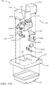
FIGS. 4A-4B illustrate exploded views of the example configuration of the wired connector assembly station ofFIGS. 3A-3B according to some implementations of the present disclosure; -
FIG. 5 illustrates a flow diagram of an example method of using the wired connector assembly station ofFIGS. 3A-3B and4A-4B to assemble a wired connector according to some implementations of the present disclosure; and -
FIG. 6 illustrates a flow diagram of an example method of a user using the wired connector assembly system ofFIG. 2 to assemble a wired connector including a set of push-click-tug procedures according to some implementations of the present disclosure. - As discussed above, a large number of wired connectors assembled using conventional assembly systems and methods do not pass testing, leading to decreased first time quality (FTQ) metrics and increased costs to fix improperly assembled wired connectors. This improper assembly typically involves one or more wires of the wired connector not being properly seated in a corresponding terminal portion of the connector. Thus, while these conventional assembly systems and methods work well for their intended purpose, an opportunity exists for improvement in the relevant art. Accordingly, improved wired connector assembly systems and methods are presented herein. These systems and methods assist an assembler in the proper assembly of a wired connector comprising a set of wires seated in a set of respective terminal portions of a connector. These improved wired connector assembly systems and methods provide for the instruction and verification of proper wire-terminal portion seating, thereby increasing FTQ metrics and decreasing costs to fix improperly assembled wired connectors. In addition, less extensive training/knowledge by human assemblers is required, which could further decrease costs and provide for more task flexibility at an assembly plant or facility.
- Referring now to
FIG. 1 , a view of an example wiredconnector 100 assembled using the assembly systems or methods according to some implementations of the present disclosure is illustrated. As shown, thewired connector 100 comprises a connector 104 (also known as a connector header, wire housing, or terminal) that defines a plurality ofterminal portions 108 in which a plurality ofrespective wires 112 are seated. Eachterminal portion 108, for example, could be a cavity defined in theconnector 104 and having a metallic or other conductive seating element disposed therein. The plurality ofwires 112 could also be electrically connected at their opposing ends to another connector/device/system (not shown). While many wired connectors include a plurality ofwires 112 seated in a plurality of respectiveterminal portions 108, it will be appreciated that in some implementations thewired connector 100 could comprise asingle wire 112 seated in a singlerespective terminal portion 108. Thus, these components will now be referred to herein as a set of terminal portions 108 (i.e., one or more terminal portions) and a set of wires 112 (i.e., one or more wires). As discussed above, one well-known procedure for performing a proper wire-terminal portion seating is the "push-click-tug" procedure where a wire is "pushed" into the respective terminal portion until a "click" indication is observed (a sound, a vibration, etc.) and the seating is then tested and verified by a "tug" on the wire, which will be discussed in greater detail below. - Referring now to
FIG. 2 , a functional block diagram of an example wiredconnector assembly system 200 according to some implementations of the present disclosure is illustrated. Theassembly system 200 comprises an assembly sub-system orstation 204 that is utilized by anassembler 208 in the assembly of a wired connector, such aswired connector 100. It will be appreciated that the term "station" as used herein refers to a device/unit or system of devices/units that are separate from other components (i.e., a sub-system) of thelarger assembly system 200 illustrated inFIG. 2 and described below. While the components ofwired connector 100 will be referred to herein for illustration/reference, it will also be appreciated that theassembly system 200 could be utilized to assembly any suitable wired connector. It will further be appreciated that the term "assembler" as used herein could refer to a human operator/user as well as an automated assembler system, such as a robotic assembler or robotic assembly system. Theassembler 208 utilizes theassembly station 204 and a set of instructions output therefrom to properly seat the set ofwires 112 in the respective set ofterminal portions 108 of theconnector 104. Depending on the type of theassembler 208, this set of instructions could be audible, visual, and/or haptic instructions, or could be computer-executable instructions (e.g., a software routine). Theconnector 104 is retrieved by theassembler 208 from a set ofconnector containers 216 of asupply system 212. Eachconnector container 216, for example, could store a different type of connectors. Theconnector 104 is scanned or otherwise identified by ascanning device 220 of thesupply system 212. While shown as a separate device, it will be appreciated that thescanning device 220 could be integrated into theassembly station 204. By scanning and identifying the type of theconnector 104, theassembly station 204 can identify and obtain a proper set of instructions for assembling thewired connector 100. - Upon identifying and retrieving the
connector 104, theassembler 208 then fixes theconnector 104 within theassembly station 204. This fixing of theconnector 104 within theassembly station 204, for example, could trigger or initiate the output of a set of instructions for theassembler 208 as to how to properly seat the set ofwires 112 within the respective set ofterminal portions 108. According to this set of instructions, theassembler 208 then retrieves the set ofwires 112 from identified container(s) of a set ofwire containers 224 of thesupply system 212. Eachwire container 224, for example, could store one or more different types of wires. In one implementation, aguide system 228 outputs the set of instructions. Some portions of thisguide system 228 could be integrated into the assembly station 204 (described in greater detail below) and other portions of theguide system 228, such as avisual indicator system 232, could be separate or distinct from theassembly station 204, such as part of thesupply system 212 as illustrated (e.g., in or proximate to the sets ofcontainers 216, 224). Thevisual indicator system 232 is configured to output a set of visual instructions (e.g., light outputs) that instruct theassembler 208 as to whichcontainer connector 104 and/or the set ofwires 112 from. It will be appreciated that thevisual indicator system 232 could only provide visual indicators relative to thewire containers 224 as theconnector 104 could be selected by theassembler 208 and then scanned by thescanning device 220 to initiate the assembly process. In one example implementation, thevisual indicator system 232 comprises a set of lights, such as one light or set of lights percontainer assembly station 204, which could also verify the proper seating of the set ofwires 112 in the respectiveterminal portions 108, such as based on measured pull force and one or more pull force thresholds, which could be calibrated at thecontroller 236 using ahandheld tensiometer 240 or other suitable device/system. - Referring now to
FIGS. 3A-3B and4A-4B and with continued reference toFIG. 2 , anexample configuration 300 of theassembly station 204 of theassembly system 200 is illustrated. This will be hereinafter referred to asassembly station 300.FIGS. 3A-3B illustrate the fixing of theconnector 104 within theassembly station 300 andFIGS. 4A-4B illustrate exploded views of theassembly station 300. Theassembly station 300 comprises abase member 304 that has alatching system 308 attached thereto. In one exemplary implementation as shown, thelatching system 308 is a pneumatic latching system that comprises areceptacle 312 defined in acentral member 316. Thereceptacle 312 is defined to receive theconnector 104 as well as other types of connectors. In this pneumatic latching configuration, thelatching system 308 further comprises latchingmembers respective end members movement 328. In the closed position, the latchingmembers connector 104 to secure it therein, whereas in the open position the latchingmembers connector 104 thereby freeing or releasing it from thereceptacle 312. Thelatching system 308 could be electronically controlled by thecontroller 236 and, in some implementations, could also be mechanically controlled via amanual release switch 332 and a manualrelease control lever 356. On an opposing side of thebase member 304, adisplay device 336 is attached. Thedisplay device 336 could be, for example only, a human-machine interface (HMI) display that is configured to output visual instructions to theassembler 208, through a hole or opening 340 defined in thebase member 304 and aligned with thedisplay device 336, as to whichterminal portions 108 to seat whichwires 112. - Also attached to the
base member 304 area pair of force orload sensors 344a, 344b. In one exemplary implementation as shown, the pair ofload sensors 344a, 344b (also referred to herein collectively as "a sensor system" or "sensor system 344") are arranged proximate to diagonally opposing corners of theopening 340 to thereby provide for a more even or uniform pull force sensing on thebase member 304 via the fixedconnector 104. While a single pair of force orload sensors 344a, 344b are shown, it will be appreciated that other quantities of load sensors could be implemented. For example only, there could be two separate pairs of load sensors, with the load sensors in each pair of load sensors being arranged in series. In one exemplary implementation, theload sensors 344a, 344b compriseload cells compressive bars load cells compressive bars sensor cover members handheld tensiometer 240. In one exemplary implementation, different pull force thresholds are utilized for proper wire-terminal portion seating verification and for emergency release of theconnector 104 to prevent potential damage. It will also be appreciated that the specific configuration of theassembly station 300 shown inFIGS. 3A-3B and4A-4B is merely one example configuration and there could be many other suitable configurations for theassembly station 204. - Referring now to
FIG. 5 and with continued reference toFIGS. 2 ,3A-3B , and4A-4B , a flow diagram of an example wiredconnector assembly method 500 of using theassembly station 300 ofFIGS. 3A-3B and4A-4B according to some implementations of the present disclosure is illustrated. At 504, thecontroller 236 outputs a set of connector instructions. This could include, for example, commanding the guide system 228 (e.g., the visual indicator system 232) to identify aparticular connector container 216 having thetarget connector 104. At 508, thecontroller 236 determines whether thetarget connector 104 has been obtained, e.g., using thescanning device 220. When true, themethod 500 proceeds to 512. Otherwise, themethod 500 returns to 504. At 512, thecontroller 236 determines whether theconnector 104 is fixed by and within thereceptacle 312 of thelatching system 308. When true, themethod 500 proceeds to 516. Otherwise, themethod 500 returns to 504. At 516, thecontroller 236 commands theguide system 228 to sequentially output a set of instructions instructing theassembler 208 how to properly seat the set ofwires 112 in the set ofterminal portions 108 of theconnector 104. In one exemplary implementation, each instruction comprises one or more visual instructions (i.e., a respective set of visual outputs), such as a visual (e.g., light) output by thevisual indicator system 232 as to whichwire container 224 that theassembler 208 is to retrieve thetarget wires 112 from and another visual (e.g., light) output by thedisplay device 336 as to whichtarget terminal portion 108 that theassembler 208 is to seat eachtarget wire 112. - At 520, the
controller 236 determines whether the sensed pulling force (e.g., as measured byload sensors 344a, 344b) satisfies a second threshold (TH2). This second threshold TH2 is indicative of a pulling force that could potentially damage theconnector 104. When this second threshold TH2 is satisfied at 520, themethod 500 proceeds to 532 where thecontroller 236 commands thelatching system 308 to the open position to release theconnector 104. Otherwise, themethod 500 continues to 524. At 524, thecontroller 236 determines whether the sensed pulling force (e.g., as measured byload sensors 344a, 344b) satisfies a lesser first threshold (TH1). This first threshold TH1 is indicative of a proper wire-terminal portion seating. When this first threshold TH1 is satisfied, themethod 500 proceeds to 528. Otherwise, the method returns to 516. At 528, thecontroller 236 determines whether the set of instructions have completed. The completion of the set of instructions is also indicative of the verification of the proper wire-terminal portion seating for each of the set ofwires 112 in the respective set ofterminal portions 108. When false, themethod 500 returns to 516. When true, however, themethod 500 proceeds to 532 where thecontroller 236 or the assembler 208 (e.g., via manual release switch 332) commands or controls thelatching system 308 to the open position to release the fully assembledwired connector 100. Themethod 500 then ends or returns to 504 for another assembly cycle. - Referring now to
FIG. 6 and with continued reference toFIG. 2 , a flow diagram of another example wiredconnector assembly method 600 using theassembly system 200 ofFIG. 2 including a set of push-click-tug procedures according to some implementations of the present disclosure is illustrated. At 604, theassembler 208 obtains the target connector 104 (e.g., from atarget connector container 216 as identified by the guide system 228). At 608, theassembler 208 obtains the target set of wires 112 (e.g., from target wire container(s) 224 as identified by the guide system 228). It will be appreciated that the set ofwires 112 could be sequentially obtained during the output of the set of instructions and not initially obtained all at once. At 612, theassembler 208 fixes theconnector 104 in theassembly station 204 ofassembly system 200. At 616, theassembler 208 observes for a first light output by theguide system 228 that is indicative of atarget wire 112 for a current push-click-tug procedure and could be initiated in response to theconnector 104 being properly fixed in theassembly station 204. When the first light output is observed by theassembler 208, themethod 600 proceeds to 620. Otherwise, the method returns to 612. - At 620, the
assembler 208 obtains thetarget wire 112 as instructed by the first light output. At 624, theassembler 208 observes for a second light output that is indicative of atarget terminal portion 108 in which theassembler 208 is to seat thetarget wire 112. When the second light output is observed by theassembler 208, themethod 600 proceeds to 628. Otherwise, themethod 600 returns to 620. At 628, theassembler 208 inserts and pushes thetarget wire 112 into thetarget terminal portion 108 of theconnector 104. At 632, theassembler 632 observes for a click indication. As previously described herein, this click indication could be an audible response (e.g., a click sound) and/or a haptic response (e.g., a vibration). When the click indication is observed by theassembler 208, themethod 600 proceeds to 636. Otherwise, themethod 600 returns to 628. At 636, theassembler 208 tugs or pulls on thetarget wire 112, which causes a pulling force on theconnector 104 that is measured/monitored by thecontroller 236 of theassembly station 204. At 640, theassembler 208 observes for a third light output that is indicative of the pulling force satisfying a threshold indicative of a proper wire-terminal portion seating. When the third light output is observed by theassembler 208, themethod 600 proceeds to 644 where theassembler 208 ceases tugging or pulling on thetarget wire 112 as it is properly seated. Otherwise, themethod 600 returns to 636. At 648, theassembler 208 or thecontroller 236 determines whether the set of instructions corresponding to the set of push-click-tug procedures have completed. When true, themethod 600 proceeds to 652. Otherwise, themethod 600 returns to 616 where the instructions and the push-click-tug procedures continued. At 652, theassembler 208 or thecontroller 236 releases theconnector 104 from theassembly station 204 to thereby obtain the fully assembledwired connector 100. Themethod 600 then ends or returns to 604 for another assembly cycle. - Example embodiments are provided so that this disclosure will be thorough, and will fully convey the scope to those who are skilled in the art. Numerous specific details are set forth such as examples of specific components, devices, and methods, to provide a thorough understanding of embodiments of the present disclosure. It will be apparent to those skilled in the art that specific details need not be employed, that example embodiments may be embodied in many different forms and that neither should be construed to limit the scope of the disclosure. In some example embodiments, well-known procedures, well-known device structures, and well-known technologies are not described in detail.
- The terminology used herein is for the purpose of describing particular example embodiments only and is not intended to be limiting. As used herein, the singular forms "a," "an," and "the" may be intended to include the plural forms as well, unless the context clearly indicates otherwise. The term "and/or" includes any and all combinations of one or more of the associated listed items. The terms "comprises," "comprising," "including," and "having," are inclusive and therefore specify the presence of stated features, integers, steps, operations, elements, and/or components, but do not preclude the presence or addition of one or more other features, integers, steps, operations, elements, components, and/or groups thereof. The method steps, processes, and operations described herein are not to be construed as necessarily requiring their performance in the particular order discussed or illustrated, unless specifically identified as an order of performance. It is also to be understood that additional or alternative steps may be employed.
- Although the terms first, second, third, etc. may be used herein to describe various elements, components, regions, layers and/or sections, these elements, components, regions, layers and/or sections should not be limited by these terms. These terms may be only used to distinguish one element, component, region, layer or section from another region, layer or section. Terms such as "first," "second," and other numerical terms when used herein do not imply a sequence or order unless clearly indicated by the context. Thus, a first element, component, region, layer or section discussed below could be termed a second element, component, region, layer or section without departing from the teachings of the example embodiments.
- As used herein, the term module may refer to, be part of, or include: an Application Specific Integrated Circuit (ASIC); an electronic circuit; a combinational logic circuit; a field programmable gate array (FPGA); a processor or a distributed network of processors (shared, dedicated, or grouped) and storage in networked clusters or datacenters that executes code or a process; other suitable components that provide the described functionality; or a combination of some or all of the above, such as in a system-on-chip. The term module may also include memory (shared, dedicated, or grouped) that stores code executed by the one or more processors.
- The term code, as used above, may include software, firmware, byte-code and/or microcode, and may refer to programs, routines, functions, classes, and/or objects. The term shared, as used above, means that some or all code from multiple modules may be executed using a single (shared) processor. In addition, some or all code from multiple modules may be stored by a single (shared) memory. The term group, as used above, means that some or all code from a single module may be executed using a group of processors. In addition, some or all code from a single module may be stored using a group of memories.
- The techniques described herein may be implemented by one or more computer programs executed by one or more processors. The computer programs include processor-executable instructions that are stored on a non-transitory tangible computer readable medium. The computer programs may also include stored data. Non-limiting examples of the non-transitory tangible computer readable medium are nonvolatile memory, magnetic storage, and optical storage.
- Some portions of the above description present the techniques described herein in terms of algorithms and symbolic representations of operations on information. These algorithmic descriptions and representations are the means used by those skilled in the data processing arts to most effectively convey the substance of their work to others skilled in the art. These operations, while described functionally or logically, are understood to be implemented by computer programs. Furthermore, it has also proven convenient at times to refer to these arrangements of operations as modules or by functional names, without loss of generality.
- Unless specifically stated otherwise as apparent from the above discussion, it is appreciated that throughout the description, discussions utilizing terms such as "processing" or "computing" or "calculating" or "determining" or "displaying" or the like, refer to the action and processes of a computer system, or similar electronic computing device, that manipulates and transforms data represented as physical (electronic) quantities within the computer system memories or registers or other such information storage, transmission or display devices.
- Certain aspects of the described techniques include process steps and instructions described herein in the form of an algorithm. It should be noted that the described process steps and instructions could be embodied in software, firmware or hardware, and when embodied in software, could be downloaded to reside on and be operated from different platforms used by real time network operating systems.
- The present disclosure also relates to an apparatus for performing the operations herein. This apparatus may be specially constructed for the required purposes, or it may comprise a general-purpose computer selectively activated or reconfigured by a computer program stored on a computer readable medium that can be accessed by the computer. Such a computer program may be stored in a tangible computer readable storage medium, such as, but is not limited to, any type of disk including floppy disks, optical disks, CD-ROMs, magnetic-optical disks, read-only memories (ROMs), random access memories (RAMs), EPROMs, EEPROMs, magnetic or optical cards, application specific integrated circuits (ASICs), or any type of media suitable for storing electronic instructions, and each coupled to a computer system bus. Furthermore, the computers referred to in the specification may include a single processor or may be architectures employing multiple processor designs for increased computing capability.
- The algorithms and operations presented herein are not inherently related to any particular computer or other apparatus. Various general-purpose systems may also be used with programs in accordance with the teachings herein, or it may prove convenient to construct more specialized apparatuses to perform the required method steps. The required structure for a variety of these systems will be apparent to those of skill in the art, along with equivalent variations. In addition, the present disclosure is not described with reference to any particular programming language. It is appreciated that a variety of programming languages may be used to implement the teachings of the present disclosure as described herein, and any references to specific languages are provided for disclosure of enablement and best mode of the present invention.
- The present disclosure is well suited to a wide variety of computer network systems over numerous topologies. Within this field, the configuration and management of large networks comprise storage devices and computers that are communicatively coupled to dissimilar computers and storage devices over a network, such as the Internet.
- The foregoing description of the embodiments has been provided for purposes of illustration and description. It is not intended to be exhaustive or to limit the disclosure. Individual elements or features of a particular embodiment are generally not limited to that particular embodiment, but, where applicable, are interchangeable and can be used in a selected embodiment, even if not specifically shown or described. The same may also be varied in many ways. Such variations are not to be regarded as a departure from the disclosure, and all such modifications are intended to be included within the scope of the disclosure.
Claims (15)
- An assembly station of an assembly system for assisting an assembler in the assembly of a connector and a set of wires seated in a set of terminal portions of the connector, respectively, the assembly station comprising:a base member;a latching system attached to the base member, defining a receptacle, and being configured to move between a closed position in which the connector is fixed within the receptacle and an open position in which the connector is removable from the receptacle;a sensor system attached to the base member and being configured to sense a pulling force on the connector while fixed within the receptacle of the latching system;at least a portion of a guide system configured to output instructions; anda controller configured to:command the guide system to sequentially output a set of instructions instructing the assembler how to properly seat the set of wires in the set of terminal portions of the connector;during the output of each particular instruction of the set of instructions, monitor, using the sensor system, the sensed pulling force on the connector; andin response to the sensed pulling force satisfying a first threshold indicative of a proper wire-terminal portion seating, command the guide system to complete the output of the particular instruction and to then sequentially output any remaining instructions of the set of instructions until the output of a final instruction is complete, including the sensed pulling force again satisfying the first threshold, and a wired connector is thereby obtained.
- The assembly system of claim 1, wherein the controller is configured to, in response to the sensed pulling force exceeding a greater second threshold indicative of a pulling force that could damage the connector, command the latching system to the open position thereby freeing the connector from the receptacle.
- The assembly system of claim 2, wherein each instruction of the set of instructions comprises a respective set of visual outputs, and wherein each visual output of the respective set of visual outputs identifies either a particular wire of the set of wires or a particular terminal portion of the connector in which the assembler is to seat the particular wire.
- The assembly system of claim 3, wherein the base member defines an opening aligned with the receptacle, wherein the guide system comprises a display device attached to a first side of the base member that opposes a second side of the base member where the latching system and the sensing system are attached, and wherein the display device is aligned with the opening.
- The assembly system of claim 4, wherein the display device is configured to output at least some of each respective set of visual outputs through the opening defined by the base member to thereby identify the particular terminal portion of the connector in which the assembler is to seat the particular wire.
- The assembly system of claim 5, wherein the guide system further comprises a visual indicator system that is distinct from the assembly station and its display device and that is configured to output at least some of each respective set of visual outputs proximate to a particular container of a set of respective containers that store the set of wires to identify the particular container from which the assembler is to retrieve the particular wire.
- The assembly system of any one of claims 1 to 6, wherein the latching system is a pneumatically-actuated latch comprising two latching members each movable along an axis and being configured to move inwardly along the axis to fixably contact the connector in the closed position and to move outwardly along the axis to not contact the connector in the open position.
- The assembly system of any one of claims 1 to 7, wherein the sensor system comprises at least one pair of force sensors attached to the base member, wherein a first force sensor of each pair of force sensors is attached to the base member proximate to a diagonally opposing corner of the receptacle relative to a second force sensor of the pair of force sensors.
- The assembly system of any one of claims 1 to 8, wherein the assembly station further comprises a manual release switch that, when actuated, moves the latching system to the open position.
- The assembly system of any one of claims 1 to 9, wherein the controller is a programmable logic controller (PLC) and the first and second thresholds are calibratable during a calibration process that utilizes an external handheld tensiometer.
- An assembly method using an assembly station of an assembly system to assist an assembler in assembling a connector and a set of wires seated in a set of terminal portions of the connector, respectively, the assembly method comprising:detecting, by a controller of the assembly station, that the connector is fixed by and within a receptacle defined by a latching system of the assembly station, wherein the latching system is attached to a base member of the assembly station and is configured to move between a closed position in which the connector is fixed within the receptacle and an open position in which the connector is removable from the receptacle;in response to detecting that the connector is fixed within the receptacle, commanding, by the controller, a guide system of the assembly system to sequentially output a set of instructions instructing the assembler how to properly seat the set of wires in the set of terminal portions of the connector;during the output of each particular instruction of the set of instructions, monitoring, by the controller and using a sensor system of the assembly station, a sensed pulling force on the connector, wherein the sensor system is also attached to the base member; andin response to the sensed pulling force satisfying a first threshold indicative of a proper wire-terminal portion seating, commanding, by the controller, the guide system to complete the output of the particular instruction and to then sequentially output any remaining instructions of the set of instructions until the output of a final instruction is complete, including the sensed pulling force again satisfying the first threshold, and a wired connector is thereby obtained.
- The assembly method of claim 11, further comprising in response to the sensed pulling force exceeding a greater second threshold indicative of a pulling force that could damage the connector, commanding, by the controller, the latching system to the open position thereby freeing the connector from the receptacle.
- The assembly method of claim 12, wherein each visual instruction of the set of visual instructions comprises a respective set of visual outputs, and wherein each visual output of the respective set of visual outputs identifies either a particular wire of the set of wires or a particular terminal portion of the connector in which the assembler is to seat the particular wire.
- The assembly method of claim 13, wherein the base member defines an opening aligned with the receptacle, wherein the guide system comprises a display device attached to a first side of the base member that opposes a second side of the base member where the latching system and the sensing system are attached, and wherein the display device is aligned with the opening.
- The assembly method of claim 14, wherein the display device is configured to output at least some of each respective set of visual outputs through the opening defined by the base member to thereby identify the particular terminal portion of the connector in which the assembler is to seat the particular wire.
Applications Claiming Priority (1)
| Application Number | Priority Date | Filing Date | Title |
|---|---|---|---|
| US16/750,461 US10958031B1 (en) | 2020-01-23 | 2020-01-23 | Terminal un-seated tester for smart kitting of wired connectors |
Publications (1)
| Publication Number | Publication Date |
|---|---|
| EP3855262A1 true EP3855262A1 (en) | 2021-07-28 |
Family
ID=74194534
Family Applications (1)
| Application Number | Title | Priority Date | Filing Date |
|---|---|---|---|
| EP21152492.1A Pending EP3855262A1 (en) | 2020-01-23 | 2021-01-20 | Terminal un-seated tester for smart kitting of wired connectors |
Country Status (3)
| Country | Link |
|---|---|
| US (1) | US10958031B1 (en) |
| EP (1) | EP3855262A1 (en) |
| CN (1) | CN113238540A (en) |
Citations (2)
| Publication number | Priority date | Publication date | Assignee | Title |
|---|---|---|---|---|
| US20090199396A1 (en) * | 2008-02-09 | 2009-08-13 | Cirris Systems Corporation | Apparatus for electrical pin installation and retention confirmation |
| WO2017122614A1 (en) * | 2016-01-12 | 2017-07-20 | 住友電装株式会社 | Terminal insertion state inspection device |
Family Cites Families (19)
| Publication number | Priority date | Publication date | Assignee | Title |
|---|---|---|---|---|
| US3627300A (en) * | 1970-03-19 | 1971-12-14 | Panduit | Wire cable harness assembly apparatus |
| GB2033169B (en) * | 1978-09-29 | 1983-05-18 | Yazaki Corp | Wire harness |
| US4566502A (en) | 1984-06-29 | 1986-01-28 | Lockheed Corporation | Wire-guide latching device for a wire-harness assembly form board |
| US4704775A (en) * | 1985-06-04 | 1987-11-10 | The Boeing Company | Turn gate for use with a robotic wire harness assembly system |
| US5829130A (en) * | 1996-11-19 | 1998-11-03 | Symex, Inc. | Method of installing an integrated data, voice, and video communication network |
| US6003852A (en) * | 1997-06-09 | 1999-12-21 | Sumitomo Wiring Systems, Ltd. | Assembly device for a wiring harness |
| JP2001287711A (en) * | 2000-04-05 | 2001-10-16 | Sumitomo Wiring Syst Ltd | Apparatus and method for bunching electric wire |
| EP1720023B1 (en) * | 2001-05-30 | 2009-02-18 | Sumitomo Wiring Systems, Ltd. | A processing system for a wiring harness, a method for testing an electrical connection of a wiring harness, computer-readable storage medium storing thereon a computer program and a wire connection assisting system |
| JP3941579B2 (en) * | 2002-04-26 | 2007-07-04 | 住友電装株式会社 | Terminal insertion position indicator |
| KR20090004123U (en) | 2007-10-29 | 2009-05-06 | 한국단자공업 주식회사 | Tensile Test Holder |
| JP2011119065A (en) | 2009-12-01 | 2011-06-16 | Mitsubishi Heavy Ind Ltd | Wire harness assembling device, and wire harness assembling method |
| US8900000B2 (en) * | 2010-02-19 | 2014-12-02 | Teledyne Odi, Inc. | Robotically mateable rotary joint electrical connector |
| CN103001097B (en) * | 2012-10-28 | 2015-03-11 | 天津长城精益汽车零部件有限公司 | Terminal plugging tool for automobile harness connectors |
| WO2015156793A1 (en) | 2014-04-09 | 2015-10-15 | Delphi Technologies, Inc. | Automatic terminated wire lead insertion machine and method of operating said machine |
| JP2017098092A (en) * | 2015-11-25 | 2017-06-01 | 住友電装株式会社 | Wire harness manufacturing support device and connector bar |
| CN206096330U (en) | 2016-10-13 | 2017-04-12 | 德尔福派克电气系统有限公司 | Electric testboard of car wiring harness guide assembly |
| CN206322938U (en) * | 2016-12-06 | 2017-07-11 | 张正 | A kind of charging plug-in connection charged suitable for automobile |
| CN106785800B (en) * | 2017-02-16 | 2023-03-21 | 天津东驰机电设备有限公司 | Automobile wire harness guiding and inserting device |
| US10964455B2 (en) * | 2017-12-17 | 2021-03-30 | Materials Technologies Corporation | Apparatus, system and method adapted to enable automated wire reading and manufacture of wire harnesses |
-
2020
- 2020-01-23 US US16/750,461 patent/US10958031B1/en active Active
-
2021
- 2021-01-20 EP EP21152492.1A patent/EP3855262A1/en active Pending
- 2021-01-25 CN CN202110097292.5A patent/CN113238540A/en active Pending
Patent Citations (2)
| Publication number | Priority date | Publication date | Assignee | Title |
|---|---|---|---|---|
| US20090199396A1 (en) * | 2008-02-09 | 2009-08-13 | Cirris Systems Corporation | Apparatus for electrical pin installation and retention confirmation |
| WO2017122614A1 (en) * | 2016-01-12 | 2017-07-20 | 住友電装株式会社 | Terminal insertion state inspection device |
Also Published As
| Publication number | Publication date |
|---|---|
| US10958031B1 (en) | 2021-03-23 |
| CN113238540A (en) | 2021-08-10 |
Similar Documents
| Publication | Publication Date | Title |
|---|---|---|
| US9851019B2 (en) | Device and method for valve signature testing | |
| US8757469B2 (en) | Binary classification of items of interest in a repeatable process | |
| KR102230405B1 (en) | Automatic data bus wire integrity verification device | |
| US20120330501A1 (en) | Vehicle hardware integrity analysis systems and methods | |
| KR101330410B1 (en) | Bms(battery management system) aging test for hev and ev | |
| SE532501C2 (en) | Method and device for position locking of nut wrenches for correcting unacceptable results in screw joint tightening | |
| CN105453141B (en) | Apparatus and method for detecting the failure in electronic system | |
| GB2246868A (en) | Diagnosing circuit faults in vehicles | |
| CN104422792B (en) | System and method for testing vehicle traction battery component | |
| DE102009025373A1 (en) | Status display device for a rechargeable automotive battery | |
| US11142345B2 (en) | System and method for performing a test procedure | |
| US10958031B1 (en) | Terminal un-seated tester for smart kitting of wired connectors | |
| CN112858976A (en) | Method for detecting a thermal event of an electrical energy store in a vehicle | |
| US10114062B2 (en) | Method and aparatus for monitoring a junction between electrical devices | |
| JP6284587B2 (en) | Simulation apparatus and simulation system | |
| CN116859262A (en) | Storage battery pack operation and maintenance method and system | |
| JP3213910B2 (en) | Battery diagnostic device | |
| US9952184B2 (en) | Ultrasonic monitoring of electrical connections | |
| JP5467601B2 (en) | Battery test apparatus, battery test method, and battery test program | |
| KR20140020825A (en) | Calibration detection system and method | |
| EP2711632A1 (en) | Glow plug, method of determining new glow plug, and glow plug drive control device | |
| US10248094B2 (en) | Hot cutover box | |
| KR101578917B1 (en) | Tester apparatus for instant short circuit and method thereof | |
| CN116774090B (en) | Energy storage battery health diagnosis method, device and equipment based on state monitoring | |
| CN104833920B (en) | The failure analysis methods and system of battery modules |
Legal Events
| Date | Code | Title | Description |
|---|---|---|---|
| PUAI | Public reference made under article 153(3) epc to a published international application that has entered the european phase |
Free format text: ORIGINAL CODE: 0009012 |
|
| STAA | Information on the status of an ep patent application or granted ep patent |
Free format text: STATUS: THE APPLICATION HAS BEEN PUBLISHED |
|
| AK | Designated contracting states |
Kind code of ref document: A1 Designated state(s): AL AT BE BG CH CY CZ DE DK EE ES FI FR GB GR HR HU IE IS IT LI LT LU LV MC MK MT NL NO PL PT RO RS SE SI SK SM TR |
|
| STAA | Information on the status of an ep patent application or granted ep patent |
Free format text: STATUS: REQUEST FOR EXAMINATION WAS MADE |
|
| 17P | Request for examination filed |
Effective date: 20220127 |
|
| RBV | Designated contracting states (corrected) |
Designated state(s): AL AT BE BG CH CY CZ DE DK EE ES FI FR GB GR HR HU IE IS IT LI LT LU LV MC MK MT NL NO PL PT RO RS SE SI SK SM TR |
|
| STAA | Information on the status of an ep patent application or granted ep patent |
Free format text: STATUS: EXAMINATION IS IN PROGRESS |
|
| 17Q | First examination report despatched |
Effective date: 20221221 |
|
| RAP3 | Party data changed (applicant data changed or rights of an application transferred) |
Owner name: APTIV TECHNOLOGIES LIMITED |
|
| RAP1 | Party data changed (applicant data changed or rights of an application transferred) |
Owner name: APTIV TECHNOLOGIES AG |
|
| RAP3 | Party data changed (applicant data changed or rights of an application transferred) |
Owner name: APTIV TECHNOLOGIES AG |