EP3855255A1 - Blockiervorrichtung für uhrwerk - Google Patents
Blockiervorrichtung für uhrwerk Download PDFInfo
- Publication number
- EP3855255A1 EP3855255A1 EP20152932.8A EP20152932A EP3855255A1 EP 3855255 A1 EP3855255 A1 EP 3855255A1 EP 20152932 A EP20152932 A EP 20152932A EP 3855255 A1 EP3855255 A1 EP 3855255A1
- Authority
- EP
- European Patent Office
- Prior art keywords
- movable part
- locking device
- stop
- movable
- locking
- Prior art date
- Legal status (The legal status is an assumption and is not a legal conclusion. Google has not performed a legal analysis and makes no representation as to the accuracy of the status listed.)
- Granted
Links
- 230000000903 blocking effect Effects 0.000 claims abstract description 10
- 238000006073 displacement reaction Methods 0.000 claims abstract description 3
- 230000008878 coupling Effects 0.000 claims 1
- 238000010168 coupling process Methods 0.000 claims 1
- 238000005859 coupling reaction Methods 0.000 claims 1
- 230000009191 jumping Effects 0.000 description 2
- PEDCQBHIVMGVHV-UHFFFAOYSA-N Glycerine Chemical compound OCC(O)CO PEDCQBHIVMGVHV-UHFFFAOYSA-N 0.000 description 1
- 238000005452 bending Methods 0.000 description 1
- 230000006835 compression Effects 0.000 description 1
- 238000007906 compression Methods 0.000 description 1
- 230000003993 interaction Effects 0.000 description 1
- 238000004519 manufacturing process Methods 0.000 description 1
- 230000002787 reinforcement Effects 0.000 description 1
- 230000000284 resting effect Effects 0.000 description 1
Images
Classifications
-
- G—PHYSICS
- G04—HOROLOGY
- G04B—MECHANICALLY-DRIVEN CLOCKS OR WATCHES; MECHANICAL PARTS OF CLOCKS OR WATCHES IN GENERAL; TIME PIECES USING THE POSITION OF THE SUN, MOON OR STARS
- G04B15/00—Escapements
- G04B15/10—Escapements with constant impulses for the regulating mechanism
-
- G—PHYSICS
- G04—HOROLOGY
- G04B—MECHANICALLY-DRIVEN CLOCKS OR WATCHES; MECHANICAL PARTS OF CLOCKS OR WATCHES IN GENERAL; TIME PIECES USING THE POSITION OF THE SUN, MOON OR STARS
- G04B13/00—Gearwork
- G04B13/002—Gearwork where rotation in one direction is changed into a stepping movement
-
- G—PHYSICS
- G04—HOROLOGY
- G04B—MECHANICALLY-DRIVEN CLOCKS OR WATCHES; MECHANICAL PARTS OF CLOCKS OR WATCHES IN GENERAL; TIME PIECES USING THE POSITION OF THE SUN, MOON OR STARS
- G04B17/00—Mechanisms for stabilising frequency
- G04B17/04—Oscillators acting by spring tension
-
- G—PHYSICS
- G04—HOROLOGY
- G04B—MECHANICALLY-DRIVEN CLOCKS OR WATCHES; MECHANICAL PARTS OF CLOCKS OR WATCHES IN GENERAL; TIME PIECES USING THE POSITION OF THE SUN, MOON OR STARS
- G04B17/00—Mechanisms for stabilising frequency
- G04B17/04—Oscillators acting by spring tension
- G04B17/045—Oscillators acting by spring tension with oscillating blade springs
-
- G—PHYSICS
- G04—HOROLOGY
- G04B—MECHANICALLY-DRIVEN CLOCKS OR WATCHES; MECHANICAL PARTS OF CLOCKS OR WATCHES IN GENERAL; TIME PIECES USING THE POSITION OF THE SUN, MOON OR STARS
- G04B19/00—Indicating the time by visual means
- G04B19/24—Clocks or watches with date or week-day indicators, i.e. calendar clocks or watches; Clockwork calendars
- G04B19/243—Clocks or watches with date or week-day indicators, i.e. calendar clocks or watches; Clockwork calendars characterised by the shape of the date indicator
- G04B19/24306—Clocks or watches with date or week-day indicators, i.e. calendar clocks or watches; Clockwork calendars characterised by the shape of the date indicator combination of different shapes, e.g. bands and discs, discs and drums
- G04B19/2432—Driving or releasing mechanisms wherein the date indicators are driven or released mechanically by a clockwork movement
- G04B19/2434—Driving or releasing mechanisms wherein the date indicators are driven or released mechanically by a clockwork movement driven or released by their own energy source which is released at regular time intervals
-
- G—PHYSICS
- G04—HOROLOGY
- G04B—MECHANICALLY-DRIVEN CLOCKS OR WATCHES; MECHANICAL PARTS OF CLOCKS OR WATCHES IN GENERAL; TIME PIECES USING THE POSITION OF THE SUN, MOON OR STARS
- G04B23/00—Arrangements producing acoustic signals at preselected times
- G04B23/02—Alarm clocks
- G04B23/025—Signal triggering
-
- G—PHYSICS
- G04—HOROLOGY
- G04B—MECHANICALLY-DRIVEN CLOCKS OR WATCHES; MECHANICAL PARTS OF CLOCKS OR WATCHES IN GENERAL; TIME PIECES USING THE POSITION OF THE SUN, MOON OR STARS
- G04B19/00—Indicating the time by visual means
- G04B19/26—Clocks or watches with indicators for tides, for the phases of the moon, or the like
- G04B19/268—Clocks or watches with indicators for tides, for the phases of the moon, or the like with indicators for the phases of the moon
Definitions
- the present invention relates to a locking device for a timepiece, capable of locking a rotating member under tension and unlocking it at determined instants to control movements by jumps of one or more moving parts.
- the rotary locking member is used, for example, to drive a jumping indicator member, to trigger a mechanism such as a striking mechanism or to periodically arm an intermediate spring of a so-called constant force mechanism.
- the drawback of this locking device is that the times at which the rotary locking member is released depend on manufacturing and assembly tolerances. This can generate inaccuracies in the display of information by the jumping indicator unit, in the triggering of the controlled mechanism. by the rotary locking member or in the quantity of energy delivered in each cycle by the intermediate spring of the so-called constant force mechanism.
- the present invention aims to remedy this drawback or at least to mitigate it.
- the second movable part of the blocking device comprises an adjustment device arranged to act on the stop device and making it possible to adjust said determined instants.
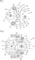
- the figures 1 and 2 show two examples of a locking device for a timepiece such as a wristwatch, a pocket watch or a clock, designed according to the teaching of patent applications WO 2018/193365 and WO 2018/193366 the respective contents of which are incorporated herein by reference.
- the locking device 10 comprises a movable frame 11 having first and second openings 12, 13 which respectively receive a rotary drive member 14 and a rotary lock member 15.
- the rotary drive members 14 and locking 15 are for example fingers, as shown in the drawings, or stars.
- the first and second openings 12, 13 may have an open contour ( figure 1 ) or closed contour ( figure 2 ).
- the rotary drive member 14 is driven continuously in a determined direction, namely the counterclockwise direction to the figure 1 and clockwise to figure 2 , by an energy source of the timepiece, typically via a cog, and alternately cooperates with first and second drive elements 16, 17 defined by the wall of the first opening 12 to move the movable frame 11 alternately in two opposite directions.
- the movable frame 11 moves in rotation around an axis A.
- it moves in translation in the direction indicated by the arrow F while being guided by a flexible guide 18 which can be monolithic with the movable frame 11.
- the rotary locking member 15 is kept under tension by a power source of the timepiece, which may be the same source of energy as that driving the rotary drive member 14 or another source of energy. energy independent of the first.
- the rotary drive member 14 rotates without driving, and preferably without touching, the movable frame 11 and the rotary blocking member 15 bears against one of two stop elements 19, 20 integral with the movable frame 11.
- the rotary drive member 14 comes into contact with one, 16, of the drive elements 16, 17 and then cooperates with it tangentially, in the manner of a gear, to move the movable frame. 11 one way for a while.
- This movement causes the stopper 19 against which it was resting to leave the path of the rotary blocking member 15, thus freeing the rotary blocking member 15.
- the latter then moves almost instantaneously to abut against the other stopper 20.
- the figure 1 shows the rotating blocking member 15 during its fall between the stop elements 19, 20.
- the figure 2 shows the rotary blocking member 15 having just come into contact with the stop member 20.
- the rotary drive member 14 then leaves the driving member 16 and continues its rotation without driving the movable frame 11
- the rotary locking member 15 remains in abutment against the stop member 20 until the rotary driving member 14 comes into contact with the other driving member 17 and cooperates with it tangentially to move the frame mobile 11 in the other direction.
- the rotary blocking member 15 is then released to rest against the first stop member 19, the rotary drive member 14 leaves the drive member 17 and the cycle repeats.
- Each jump of the rotary locking member 15 between the two stop elements 19, 20 causes a corresponding jump of an indicator member, such as a needle, activates a mechanism such as a striking mechanism or arms a spring intermediary of a so-called constant force mechanism, for example.
- the indicator member can indicate information such as the date, the week, the day of the week, the month or the moon phase.
- each stop element 19, 20 with which the rotary locking member 15 cooperates can be concentric with the movable frame 11, so that the support of the member rotary locking 15 on the stopper 19, 20 does not move the movable frame 11.
- the stopper surface 21, 22 can be inclined so that the rotary locking member 15 exerts on the movable frame 11 a draft which immobilizes the movable frame 11 by compensating for an elastic return torque applied to the movable frame 11.
- each stop element 19, 20 with which the rotary locking member 15 cooperates may be parallel to the direction of movement of the movable frame 11, in particular if the guide flexible 18 is arranged so as not to apply any elastic return force on the movable frame 11.
- the stop surface 21, 22 can be inclined, as shown, so that the rotary locking member 15 exerts on the movable frame 11 a draw which immobilizes the movable frame 11 by compensating for an elastic return force exerted by the flexible guide 18 and / or by causing the wall of the second opening 13 to abut against the rotary locking member 15.
- each stop element 19, 20 constitutes or makes part of a rigid block 23, 24 suspended from a rigid base 25, 26 by a flexible guide 27, 28.
- the rigid base 25, 26 - flexible guide 27, 28 - rigid block 23, 24 assembly can be part of the frame mobile 11 and even be monolithic with the rest of the mobile frame 11, as in the example of figure 1 , or be attached to the mobile frame 11, as in the example of figure 2 .
- each flexible guide 27, 28 is of the type with a remote center of rotation called "RCC" (Remote Center Compliance) and guides the corresponding rigid block 23, 24 in rotation around the center of curvature of the corresponding stop surface 21, 22 , in other words, parallel to said stop surface.
- each flexible guide 27, 28 comprises two parallel elastic blades and guides the corresponding rigid block 23, 24 in translation parallel to the corresponding stop surface 21, 22.
- Each flexible guide 27, 28 is prestressed and permanently applies the corresponding rigid block 23, 24 against an adjustment element 29, 30, such as an eccentric (variant shown) or an adjustment screw, mounted on the mobile frame 11.
- an adjustment element 29, 30 such as an eccentric (variant shown) or an adjustment screw, mounted on the mobile frame 11.
- each flexible guide 27, 28 is low in the guiding direction of the corresponding rigid block 23, 24 (the elastic blades being urged in this direction in bending) but is high in the other directions, in particular in the direction of feedback vis-à-vis the rotary locking member 15 (the elastic blades being urged in this direction mainly in compression for one and mainly in traction for the other).
- the two stops 19, 20 are adjustable, as described above and shown in the drawings.
- the movable frame 11 consists of two parts 11a, 11b integral, therefore connected kinematically, respectively comprising the first opening 12 and the second opening 13.
- these two parts 11a, 11b could be separated and kinematically connected by a connection of the gear type or the like, preferably without play, in the manner for example of the embodiment shown in FIG. 7 of the application WO 2018/193365 .
- the assembly comprising the rigid bases 25, 26, the flexible guides 27, 28 and the rigid blocks 23, 24 would be mounted on, or monolithic with, the second part 11b and the adjustment elements 29, 30 would also be mounted on the second part 11b.
- the openings 12, 13 could not be coplanar but superimposed. More than two drive elements and / or more than two stop elements could be provided.
- the wall of the first opening 12 could define additional drive elements to allow a pre-reinforcement of the movable frame 11 or of the part 11a before its displacement leading to the release of the rotary locking member 15.
- the flexible guides 27, 28 could be replaced by an arrangement of slides and return springs.
Landscapes
- Physics & Mathematics (AREA)
- General Physics & Mathematics (AREA)
- Acoustics & Sound (AREA)
- Transmission Devices (AREA)
Priority Applications (1)
| Application Number | Priority Date | Filing Date | Title |
|---|---|---|---|
| EP20152932.8A EP3855255B1 (de) | 2020-01-21 | 2020-01-21 | Blockiervorrichtung für uhrwerk |
Applications Claiming Priority (1)
| Application Number | Priority Date | Filing Date | Title |
|---|---|---|---|
| EP20152932.8A EP3855255B1 (de) | 2020-01-21 | 2020-01-21 | Blockiervorrichtung für uhrwerk |
Publications (2)
| Publication Number | Publication Date |
|---|---|
| EP3855255A1 true EP3855255A1 (de) | 2021-07-28 |
| EP3855255B1 EP3855255B1 (de) | 2022-06-22 |
Family
ID=69185536
Family Applications (1)
| Application Number | Title | Priority Date | Filing Date |
|---|---|---|---|
| EP20152932.8A Active EP3855255B1 (de) | 2020-01-21 | 2020-01-21 | Blockiervorrichtung für uhrwerk |
Country Status (1)
| Country | Link |
|---|---|
| EP (1) | EP3855255B1 (de) |
Citations (3)
| Publication number | Priority date | Publication date | Assignee | Title |
|---|---|---|---|---|
| EP2068210A2 (de) * | 2007-12-04 | 2009-06-10 | Chronode SA | Auslösevorrichtung |
| CH704331A1 (fr) * | 2011-01-13 | 2012-07-13 | Greubel Forsey S A | Pièce d'horlogerie. |
| WO2018193365A1 (fr) | 2017-04-18 | 2018-10-25 | Patek Philippe Sa Geneve | Dispositif de blocage pour l'horlogerie |
-
2020
- 2020-01-21 EP EP20152932.8A patent/EP3855255B1/de active Active
Patent Citations (4)
| Publication number | Priority date | Publication date | Assignee | Title |
|---|---|---|---|---|
| EP2068210A2 (de) * | 2007-12-04 | 2009-06-10 | Chronode SA | Auslösevorrichtung |
| CH704331A1 (fr) * | 2011-01-13 | 2012-07-13 | Greubel Forsey S A | Pièce d'horlogerie. |
| WO2018193365A1 (fr) | 2017-04-18 | 2018-10-25 | Patek Philippe Sa Geneve | Dispositif de blocage pour l'horlogerie |
| WO2018193366A1 (fr) | 2017-04-18 | 2018-10-25 | Patek Philippe Sa Geneve | Dispositif de blocage pour l'horlogerie |
Also Published As
| Publication number | Publication date |
|---|---|
| EP3855255B1 (de) | 2022-06-22 |
Similar Documents
| Publication | Publication Date | Title |
|---|---|---|
| CH698827B1 (fr) | Dispositif de remise à zéro pour une pièce d'horlogerie. | |
| EP3612896B1 (de) | Verriegelungsvorrichtung fuer uhrwerkmechanismus | |
| EP2541346B1 (de) | Vorrichtung zum Zurückstellen eines Anzeigeorgans für eine mit der Zeit zusammenhängenden Größe in eine voreingestellte Position | |
| EP3483663B1 (de) | Antriebsvorrichtung für kalendersystem einer uhr | |
| EP1617305B1 (de) | Arretiervorrichtung bei der Zeigerstellung einer Uhr mit einem Tourbillon | |
| EP1983391A1 (de) | Ankerhemmung für Uhren | |
| EP3602202B1 (de) | Vorrichtung zur einstellung von funktionen einer uhr | |
| EP3059642B1 (de) | Uhrmechanismus | |
| EP3584643B1 (de) | Augenblicklich schaltende steuervorrichtung für datumsanzeige von uhren | |
| EP2957964B1 (de) | Kippkupplung für uhren | |
| EP3855255B1 (de) | Blockiervorrichtung für uhrwerk | |
| EP3401739B1 (de) | Uhrwerk, das eine konstantkraftvorrichtung umfasst | |
| EP2096504A2 (de) | Mechanismus zur Anzeige der toten Sekunden | |
| CH708338A2 (fr) | Mécanisme correcteur pas-à-pas. | |
| EP1890205B1 (de) | Vorrichtung zur Nullrückstellung für eine Uhr | |
| EP1430367B1 (de) | Chronographen-mechanismus | |
| EP1710635A1 (de) | Betätigungsvorrichtung für eine Uhr und eine Uhr mit derartiger Vorrichtung | |
| WO2007060150A2 (fr) | Mouvement d'horlogerie | |
| CH708741A2 (fr) | Dispositif correcteur pour pièce d'horlogerie. | |
| EP4312083A1 (de) | Kupplungs-ausrückvorrichtung für uhr | |
| EP4060428B1 (de) | Betätigungsmechanismus für uhrwerk, insbesondere chronographenmechanismus mit einem solchen betätigungsmechanismus | |
| CH717664B1 (fr) | Pièce d'horlogerie comprenant un dispositif de commande étanche. | |
| EP4307052A1 (de) | Chronographenmechanismus für uhrwerk | |
| EP4361739A1 (de) | Funktionsauswahlsystem für eine uhr | |
| EP2672334A1 (de) | Uhrmechanismus mit Reduzierung der Verzahnungsspiele |
Legal Events
| Date | Code | Title | Description |
|---|---|---|---|
| PUAI | Public reference made under article 153(3) epc to a published international application that has entered the european phase |
Free format text: ORIGINAL CODE: 0009012 |
|
| STAA | Information on the status of an ep patent application or granted ep patent |
Free format text: STATUS: THE APPLICATION HAS BEEN PUBLISHED |
|
| AK | Designated contracting states |
Kind code of ref document: A1 Designated state(s): AL AT BE BG CH CY CZ DE DK EE ES FI FR GB GR HR HU IE IS IT LI LT LU LV MC MK MT NL NO PL PT RO RS SE SI SK SM TR |
|
| STAA | Information on the status of an ep patent application or granted ep patent |
Free format text: STATUS: REQUEST FOR EXAMINATION WAS MADE |
|
| 17P | Request for examination filed |
Effective date: 20211006 |
|
| RBV | Designated contracting states (corrected) |
Designated state(s): AL AT BE BG CH CY CZ DE DK EE ES FI FR GB GR HR HU IE IS IT LI LT LU LV MC MK MT NL NO PL PT RO RS SE SI SK SM TR |
|
| GRAP | Despatch of communication of intention to grant a patent |
Free format text: ORIGINAL CODE: EPIDOSNIGR1 |
|
| STAA | Information on the status of an ep patent application or granted ep patent |
Free format text: STATUS: GRANT OF PATENT IS INTENDED |
|
| INTG | Intention to grant announced |
Effective date: 20220210 |
|
| GRAS | Grant fee paid |
Free format text: ORIGINAL CODE: EPIDOSNIGR3 |
|
| GRAA | (expected) grant |
Free format text: ORIGINAL CODE: 0009210 |
|
| STAA | Information on the status of an ep patent application or granted ep patent |
Free format text: STATUS: THE PATENT HAS BEEN GRANTED |
|
| AK | Designated contracting states |
Kind code of ref document: B1 Designated state(s): AL AT BE BG CH CY CZ DE DK EE ES FI FR GB GR HR HU IE IS IT LI LT LU LV MC MK MT NL NO PL PT RO RS SE SI SK SM TR |
|
| REG | Reference to a national code |
Ref country code: GB Ref legal event code: FG4D Free format text: NOT ENGLISH |
|
| REG | Reference to a national code |
Ref country code: CH Ref legal event code: EP |
|
| REG | Reference to a national code |
Ref country code: DE Ref legal event code: R096 Ref document number: 602020003588 Country of ref document: DE |
|
| REG | Reference to a national code |
Ref country code: AT Ref legal event code: REF Ref document number: 1500162 Country of ref document: AT Kind code of ref document: T Effective date: 20220715 |
|
| REG | Reference to a national code |
Ref country code: IE Ref legal event code: FG4D Free format text: LANGUAGE OF EP DOCUMENT: FRENCH |
|
| REG | Reference to a national code |
Ref country code: LT Ref legal event code: MG9D |
|
| REG | Reference to a national code |
Ref country code: NL Ref legal event code: MP Effective date: 20220622 |
|
| PG25 | Lapsed in a contracting state [announced via postgrant information from national office to epo] |
Ref country code: SE Free format text: LAPSE BECAUSE OF FAILURE TO SUBMIT A TRANSLATION OF THE DESCRIPTION OR TO PAY THE FEE WITHIN THE PRESCRIBED TIME-LIMIT Effective date: 20220622 Ref country code: NO Free format text: LAPSE BECAUSE OF FAILURE TO SUBMIT A TRANSLATION OF THE DESCRIPTION OR TO PAY THE FEE WITHIN THE PRESCRIBED TIME-LIMIT Effective date: 20220922 Ref country code: LT Free format text: LAPSE BECAUSE OF FAILURE TO SUBMIT A TRANSLATION OF THE DESCRIPTION OR TO PAY THE FEE WITHIN THE PRESCRIBED TIME-LIMIT Effective date: 20220622 Ref country code: HR Free format text: LAPSE BECAUSE OF FAILURE TO SUBMIT A TRANSLATION OF THE DESCRIPTION OR TO PAY THE FEE WITHIN THE PRESCRIBED TIME-LIMIT Effective date: 20220622 Ref country code: GR Free format text: LAPSE BECAUSE OF FAILURE TO SUBMIT A TRANSLATION OF THE DESCRIPTION OR TO PAY THE FEE WITHIN THE PRESCRIBED TIME-LIMIT Effective date: 20220923 Ref country code: FI Free format text: LAPSE BECAUSE OF FAILURE TO SUBMIT A TRANSLATION OF THE DESCRIPTION OR TO PAY THE FEE WITHIN THE PRESCRIBED TIME-LIMIT Effective date: 20220622 Ref country code: BG Free format text: LAPSE BECAUSE OF FAILURE TO SUBMIT A TRANSLATION OF THE DESCRIPTION OR TO PAY THE FEE WITHIN THE PRESCRIBED TIME-LIMIT Effective date: 20220922 |
|
| REG | Reference to a national code |
Ref country code: AT Ref legal event code: MK05 Ref document number: 1500162 Country of ref document: AT Kind code of ref document: T Effective date: 20220622 |
|
| PG25 | Lapsed in a contracting state [announced via postgrant information from national office to epo] |
Ref country code: RS Free format text: LAPSE BECAUSE OF FAILURE TO SUBMIT A TRANSLATION OF THE DESCRIPTION OR TO PAY THE FEE WITHIN THE PRESCRIBED TIME-LIMIT Effective date: 20220622 Ref country code: LV Free format text: LAPSE BECAUSE OF FAILURE TO SUBMIT A TRANSLATION OF THE DESCRIPTION OR TO PAY THE FEE WITHIN THE PRESCRIBED TIME-LIMIT Effective date: 20220622 |
|
| PG25 | Lapsed in a contracting state [announced via postgrant information from national office to epo] |
Ref country code: NL Free format text: LAPSE BECAUSE OF FAILURE TO SUBMIT A TRANSLATION OF THE DESCRIPTION OR TO PAY THE FEE WITHIN THE PRESCRIBED TIME-LIMIT Effective date: 20220622 |
|
| PG25 | Lapsed in a contracting state [announced via postgrant information from national office to epo] |
Ref country code: SM Free format text: LAPSE BECAUSE OF FAILURE TO SUBMIT A TRANSLATION OF THE DESCRIPTION OR TO PAY THE FEE WITHIN THE PRESCRIBED TIME-LIMIT Effective date: 20220622 Ref country code: SK Free format text: LAPSE BECAUSE OF FAILURE TO SUBMIT A TRANSLATION OF THE DESCRIPTION OR TO PAY THE FEE WITHIN THE PRESCRIBED TIME-LIMIT Effective date: 20220622 Ref country code: RO Free format text: LAPSE BECAUSE OF FAILURE TO SUBMIT A TRANSLATION OF THE DESCRIPTION OR TO PAY THE FEE WITHIN THE PRESCRIBED TIME-LIMIT Effective date: 20220622 Ref country code: PT Free format text: LAPSE BECAUSE OF FAILURE TO SUBMIT A TRANSLATION OF THE DESCRIPTION OR TO PAY THE FEE WITHIN THE PRESCRIBED TIME-LIMIT Effective date: 20221024 Ref country code: ES Free format text: LAPSE BECAUSE OF FAILURE TO SUBMIT A TRANSLATION OF THE DESCRIPTION OR TO PAY THE FEE WITHIN THE PRESCRIBED TIME-LIMIT Effective date: 20220622 Ref country code: EE Free format text: LAPSE BECAUSE OF FAILURE TO SUBMIT A TRANSLATION OF THE DESCRIPTION OR TO PAY THE FEE WITHIN THE PRESCRIBED TIME-LIMIT Effective date: 20220622 Ref country code: CZ Free format text: LAPSE BECAUSE OF FAILURE TO SUBMIT A TRANSLATION OF THE DESCRIPTION OR TO PAY THE FEE WITHIN THE PRESCRIBED TIME-LIMIT Effective date: 20220622 Ref country code: AT Free format text: LAPSE BECAUSE OF FAILURE TO SUBMIT A TRANSLATION OF THE DESCRIPTION OR TO PAY THE FEE WITHIN THE PRESCRIBED TIME-LIMIT Effective date: 20220622 |
|
| PG25 | Lapsed in a contracting state [announced via postgrant information from national office to epo] |
Ref country code: PL Free format text: LAPSE BECAUSE OF FAILURE TO SUBMIT A TRANSLATION OF THE DESCRIPTION OR TO PAY THE FEE WITHIN THE PRESCRIBED TIME-LIMIT Effective date: 20220622 Ref country code: IS Free format text: LAPSE BECAUSE OF FAILURE TO SUBMIT A TRANSLATION OF THE DESCRIPTION OR TO PAY THE FEE WITHIN THE PRESCRIBED TIME-LIMIT Effective date: 20221022 |
|
| REG | Reference to a national code |
Ref country code: DE Ref legal event code: R097 Ref document number: 602020003588 Country of ref document: DE |
|
| PG25 | Lapsed in a contracting state [announced via postgrant information from national office to epo] |
Ref country code: AL Free format text: LAPSE BECAUSE OF FAILURE TO SUBMIT A TRANSLATION OF THE DESCRIPTION OR TO PAY THE FEE WITHIN THE PRESCRIBED TIME-LIMIT Effective date: 20220622 |
|
| PG25 | Lapsed in a contracting state [announced via postgrant information from national office to epo] |
Ref country code: DK Free format text: LAPSE BECAUSE OF FAILURE TO SUBMIT A TRANSLATION OF THE DESCRIPTION OR TO PAY THE FEE WITHIN THE PRESCRIBED TIME-LIMIT Effective date: 20220622 |
|
| PLBE | No opposition filed within time limit |
Free format text: ORIGINAL CODE: 0009261 |
|
| STAA | Information on the status of an ep patent application or granted ep patent |
Free format text: STATUS: NO OPPOSITION FILED WITHIN TIME LIMIT |
|
| 26N | No opposition filed |
Effective date: 20230323 |
|
| P01 | Opt-out of the competence of the unified patent court (upc) registered |
Effective date: 20230521 |
|
| REG | Reference to a national code |
Ref country code: DE Ref legal event code: R119 Ref document number: 602020003588 Country of ref document: DE |
|
| PG25 | Lapsed in a contracting state [announced via postgrant information from national office to epo] |
Ref country code: SI Free format text: LAPSE BECAUSE OF FAILURE TO SUBMIT A TRANSLATION OF THE DESCRIPTION OR TO PAY THE FEE WITHIN THE PRESCRIBED TIME-LIMIT Effective date: 20220622 |
|
| PG25 | Lapsed in a contracting state [announced via postgrant information from national office to epo] |
Ref country code: LU Free format text: LAPSE BECAUSE OF NON-PAYMENT OF DUE FEES Effective date: 20230121 |
|
| REG | Reference to a national code |
Ref country code: BE Ref legal event code: MM Effective date: 20230131 |
|
| PG25 | Lapsed in a contracting state [announced via postgrant information from national office to epo] |
Ref country code: DE Free format text: LAPSE BECAUSE OF NON-PAYMENT OF DUE FEES Effective date: 20230801 |
|
| PG25 | Lapsed in a contracting state [announced via postgrant information from national office to epo] |
Ref country code: FR Free format text: LAPSE BECAUSE OF NON-PAYMENT OF DUE FEES Effective date: 20230131 Ref country code: BE Free format text: LAPSE BECAUSE OF NON-PAYMENT OF DUE FEES Effective date: 20230131 |
|
| PG25 | Lapsed in a contracting state [announced via postgrant information from national office to epo] |
Ref country code: IT Free format text: LAPSE BECAUSE OF FAILURE TO SUBMIT A TRANSLATION OF THE DESCRIPTION OR TO PAY THE FEE WITHIN THE PRESCRIBED TIME-LIMIT Effective date: 20220622 Ref country code: IE Free format text: LAPSE BECAUSE OF NON-PAYMENT OF DUE FEES Effective date: 20230121 |
|
| PGFP | Annual fee paid to national office [announced via postgrant information from national office to epo] |
Ref country code: CH Payment date: 20240201 Year of fee payment: 5 |
|
| PG25 | Lapsed in a contracting state [announced via postgrant information from national office to epo] |
Ref country code: MC Free format text: LAPSE BECAUSE OF FAILURE TO SUBMIT A TRANSLATION OF THE DESCRIPTION OR TO PAY THE FEE WITHIN THE PRESCRIBED TIME-LIMIT Effective date: 20220622 |
|
| PG25 | Lapsed in a contracting state [announced via postgrant information from national office to epo] |
Ref country code: MC Free format text: LAPSE BECAUSE OF FAILURE TO SUBMIT A TRANSLATION OF THE DESCRIPTION OR TO PAY THE FEE WITHIN THE PRESCRIBED TIME-LIMIT Effective date: 20220622 |