EP3855238A1 - Light modulated photodiode-based display monitor system - Google Patents
Light modulated photodiode-based display monitor system Download PDFInfo
- Publication number
- EP3855238A1 EP3855238A1 EP21153316.1A EP21153316A EP3855238A1 EP 3855238 A1 EP3855238 A1 EP 3855238A1 EP 21153316 A EP21153316 A EP 21153316A EP 3855238 A1 EP3855238 A1 EP 3855238A1
- Authority
- EP
- European Patent Office
- Prior art keywords
- display
- signal
- light
- photodiode
- hud
- Prior art date
- Legal status (The legal status is an assumption and is not a legal conclusion. Google has not performed a legal analysis and makes no representation as to the accuracy of the status listed.)
- Granted
Links
Images


Classifications
-
- G—PHYSICS
- G09—EDUCATION; CRYPTOGRAPHY; DISPLAY; ADVERTISING; SEALS
- G09G—ARRANGEMENTS OR CIRCUITS FOR CONTROL OF INDICATING DEVICES USING STATIC MEANS TO PRESENT VARIABLE INFORMATION
- G09G3/00—Control arrangements or circuits, of interest only in connection with visual indicators other than cathode-ray tubes
- G09G3/006—Electronic inspection or testing of displays and display drivers, e.g. of LED or LCD displays
-
- G—PHYSICS
- G02—OPTICS
- G02B—OPTICAL ELEMENTS, SYSTEMS OR APPARATUS
- G02B27/00—Optical systems or apparatus not provided for by any of the groups G02B1/00 - G02B26/00, G02B30/00
- G02B27/01—Head-up displays
-
- G—PHYSICS
- G01—MEASURING; TESTING
- G01J—MEASUREMENT OF INTENSITY, VELOCITY, SPECTRAL CONTENT, POLARISATION, PHASE OR PULSE CHARACTERISTICS OF INFRARED, VISIBLE OR ULTRAVIOLET LIGHT; COLORIMETRY; RADIATION PYROMETRY
- G01J1/00—Photometry, e.g. photographic exposure meter
- G01J1/02—Details
- G01J1/04—Optical or mechanical part supplementary adjustable parts
- G01J1/0407—Optical elements not provided otherwise, e.g. manifolds, windows, holograms, gratings
- G01J1/0414—Optical elements not provided otherwise, e.g. manifolds, windows, holograms, gratings using plane or convex mirrors, parallel phase plates, or plane beam-splitters
-
- G—PHYSICS
- G01—MEASURING; TESTING
- G01J—MEASUREMENT OF INTENSITY, VELOCITY, SPECTRAL CONTENT, POLARISATION, PHASE OR PULSE CHARACTERISTICS OF INFRARED, VISIBLE OR ULTRAVIOLET LIGHT; COLORIMETRY; RADIATION PYROMETRY
- G01J1/00—Photometry, e.g. photographic exposure meter
- G01J1/02—Details
- G01J1/04—Optical or mechanical part supplementary adjustable parts
- G01J1/0407—Optical elements not provided otherwise, e.g. manifolds, windows, holograms, gratings
- G01J1/0429—Optical elements not provided otherwise, e.g. manifolds, windows, holograms, gratings using polarisation elements
-
- G—PHYSICS
- G01—MEASURING; TESTING
- G01J—MEASUREMENT OF INTENSITY, VELOCITY, SPECTRAL CONTENT, POLARISATION, PHASE OR PULSE CHARACTERISTICS OF INFRARED, VISIBLE OR ULTRAVIOLET LIGHT; COLORIMETRY; RADIATION PYROMETRY
- G01J1/00—Photometry, e.g. photographic exposure meter
- G01J1/42—Photometry, e.g. photographic exposure meter using electric radiation detectors
- G01J1/44—Electric circuits
-
- G—PHYSICS
- G02—OPTICS
- G02F—OPTICAL DEVICES OR ARRANGEMENTS FOR THE CONTROL OF LIGHT BY MODIFICATION OF THE OPTICAL PROPERTIES OF THE MEDIA OF THE ELEMENTS INVOLVED THEREIN; NON-LINEAR OPTICS; FREQUENCY-CHANGING OF LIGHT; OPTICAL LOGIC ELEMENTS; OPTICAL ANALOGUE/DIGITAL CONVERTERS
- G02F1/00—Devices or arrangements for the control of the intensity, colour, phase, polarisation or direction of light arriving from an independent light source, e.g. switching, gating or modulating; Non-linear optics
- G02F1/01—Devices or arrangements for the control of the intensity, colour, phase, polarisation or direction of light arriving from an independent light source, e.g. switching, gating or modulating; Non-linear optics for the control of the intensity, phase, polarisation or colour
- G02F1/13—Devices or arrangements for the control of the intensity, colour, phase, polarisation or direction of light arriving from an independent light source, e.g. switching, gating or modulating; Non-linear optics for the control of the intensity, phase, polarisation or colour based on liquid crystals, e.g. single liquid crystal display cells
- G02F1/1306—Details
- G02F1/1309—Repairing; Testing
-
- G—PHYSICS
- G01—MEASURING; TESTING
- G01J—MEASUREMENT OF INTENSITY, VELOCITY, SPECTRAL CONTENT, POLARISATION, PHASE OR PULSE CHARACTERISTICS OF INFRARED, VISIBLE OR ULTRAVIOLET LIGHT; COLORIMETRY; RADIATION PYROMETRY
- G01J1/00—Photometry, e.g. photographic exposure meter
- G01J1/42—Photometry, e.g. photographic exposure meter using electric radiation detectors
- G01J2001/4238—Pulsed light
-
- G—PHYSICS
- G01—MEASURING; TESTING
- G01J—MEASUREMENT OF INTENSITY, VELOCITY, SPECTRAL CONTENT, POLARISATION, PHASE OR PULSE CHARACTERISTICS OF INFRARED, VISIBLE OR ULTRAVIOLET LIGHT; COLORIMETRY; RADIATION PYROMETRY
- G01J1/00—Photometry, e.g. photographic exposure meter
- G01J1/42—Photometry, e.g. photographic exposure meter using electric radiation detectors
- G01J1/44—Electric circuits
- G01J2001/4446—Type of detector
- G01J2001/446—Photodiode
-
- G—PHYSICS
- G02—OPTICS
- G02F—OPTICAL DEVICES OR ARRANGEMENTS FOR THE CONTROL OF LIGHT BY MODIFICATION OF THE OPTICAL PROPERTIES OF THE MEDIA OF THE ELEMENTS INVOLVED THEREIN; NON-LINEAR OPTICS; FREQUENCY-CHANGING OF LIGHT; OPTICAL LOGIC ELEMENTS; OPTICAL ANALOGUE/DIGITAL CONVERTERS
- G02F1/00—Devices or arrangements for the control of the intensity, colour, phase, polarisation or direction of light arriving from an independent light source, e.g. switching, gating or modulating; Non-linear optics
- G02F1/01—Devices or arrangements for the control of the intensity, colour, phase, polarisation or direction of light arriving from an independent light source, e.g. switching, gating or modulating; Non-linear optics for the control of the intensity, phase, polarisation or colour
- G02F1/13—Devices or arrangements for the control of the intensity, colour, phase, polarisation or direction of light arriving from an independent light source, e.g. switching, gating or modulating; Non-linear optics for the control of the intensity, phase, polarisation or colour based on liquid crystals, e.g. single liquid crystal display cells
- G02F1/133—Constructional arrangements; Operation of liquid crystal cells; Circuit arrangements
- G02F1/13306—Circuit arrangements or driving methods for the control of single liquid crystal cells
- G02F1/13312—Circuits comprising photodetectors for purposes other than feedback
-
- G—PHYSICS
- G02—OPTICS
- G02F—OPTICAL DEVICES OR ARRANGEMENTS FOR THE CONTROL OF LIGHT BY MODIFICATION OF THE OPTICAL PROPERTIES OF THE MEDIA OF THE ELEMENTS INVOLVED THEREIN; NON-LINEAR OPTICS; FREQUENCY-CHANGING OF LIGHT; OPTICAL LOGIC ELEMENTS; OPTICAL ANALOGUE/DIGITAL CONVERTERS
- G02F1/00—Devices or arrangements for the control of the intensity, colour, phase, polarisation or direction of light arriving from an independent light source, e.g. switching, gating or modulating; Non-linear optics
- G02F1/01—Devices or arrangements for the control of the intensity, colour, phase, polarisation or direction of light arriving from an independent light source, e.g. switching, gating or modulating; Non-linear optics for the control of the intensity, phase, polarisation or colour
- G02F1/13—Devices or arrangements for the control of the intensity, colour, phase, polarisation or direction of light arriving from an independent light source, e.g. switching, gating or modulating; Non-linear optics for the control of the intensity, phase, polarisation or colour based on liquid crystals, e.g. single liquid crystal display cells
- G02F1/133—Constructional arrangements; Operation of liquid crystal cells; Circuit arrangements
- G02F1/13306—Circuit arrangements or driving methods for the control of single liquid crystal cells
- G02F1/13318—Circuits comprising a photodetector
-
- G—PHYSICS
- G02—OPTICS
- G02F—OPTICAL DEVICES OR ARRANGEMENTS FOR THE CONTROL OF LIGHT BY MODIFICATION OF THE OPTICAL PROPERTIES OF THE MEDIA OF THE ELEMENTS INVOLVED THEREIN; NON-LINEAR OPTICS; FREQUENCY-CHANGING OF LIGHT; OPTICAL LOGIC ELEMENTS; OPTICAL ANALOGUE/DIGITAL CONVERTERS
- G02F1/00—Devices or arrangements for the control of the intensity, colour, phase, polarisation or direction of light arriving from an independent light source, e.g. switching, gating or modulating; Non-linear optics
- G02F1/01—Devices or arrangements for the control of the intensity, colour, phase, polarisation or direction of light arriving from an independent light source, e.g. switching, gating or modulating; Non-linear optics for the control of the intensity, phase, polarisation or colour
- G02F1/13—Devices or arrangements for the control of the intensity, colour, phase, polarisation or direction of light arriving from an independent light source, e.g. switching, gating or modulating; Non-linear optics for the control of the intensity, phase, polarisation or colour based on liquid crystals, e.g. single liquid crystal display cells
- G02F1/133—Constructional arrangements; Operation of liquid crystal cells; Circuit arrangements
- G02F1/136—Liquid crystal cells structurally associated with a semi-conducting layer or substrate, e.g. cells forming part of an integrated circuit
- G02F1/1362—Active matrix addressed cells
- G02F1/136277—Active matrix addressed cells formed on a semiconductor substrate, e.g. of silicon
-
- G—PHYSICS
- G09—EDUCATION; CRYPTOGRAPHY; DISPLAY; ADVERTISING; SEALS
- G09G—ARRANGEMENTS OR CIRCUITS FOR CONTROL OF INDICATING DEVICES USING STATIC MEANS TO PRESENT VARIABLE INFORMATION
- G09G2330/00—Aspects of power supply; Aspects of display protection and defect management
- G09G2330/12—Test circuits or failure detection circuits included in a display system, as permanent part thereof
Definitions
- Head-up displays are computer-generated displays that present data on a transparent medium (e.g., a windshield for an aircraft or a visor for a helmet), allowing the user to see the data without having to look away from their usual viewpoints.
- Data provided by HUDs often offer both information regarding the current status of the vehicle, such as speed as direction, as well as warnings of systems that are not in compliance. HUDs often require rapid updating of displayed data to ensure that the user has the information required for safe operation of the vehicle.
- HUDs are susceptible to malfunctioning while in use.
- the display on a HUD may freeze up, preventing the HUD from updating the displayed data.
- a HUD may flip the displayed image.
- HUDs are monitored so that a malfunctioning HUD may be quickly detected and have the problem addressed.
- a test section of a display may be dedicated to blinking between on and off states (e.g., white and black screen states), while a detector adjacent to the test section measures the rate of blinking by the test section and compares that information to an expected value. If the expected value is not detected, then the HUD will be flagged as malfunctioning.
- Strategies for detecting a predicted signal of a test section of a display are often compromised by light generated by the area of the display intended for viewing, which can interfere with the detection of light of the test section by the detector.
- a light-modulated photodiode-based monitor for detecting a control signal of a display includes an emitter configured to emit a pulsed signal. In one or more embodiments, the light-modulated photodiode-based monitor further includes a polarizer configured to linearly polarize the pulsed signal. In one or more embodiments, the light-modulated photodiode-based monitor further includes one or more fold mirrors. In one or more embodiments, the one or more fold mirrors are configured to reflect the pulsed signal from the emitter onto a test portion. In one or more embodiments, the one or more fold mirrors are configured to reflect the pulsed signal that has reflected off of the test portion.
- the light-modulated photodiode-based monitor further includes an analyzer, configured to block or transmit the polarized pulse signal reflected from at least one of the fold mirror or the test portion. In one or more embodiments, the light-modulated photodiode-based monitor further includes a detector configured to receive the pulsed signal transmitted from the analyzer and convert the pulsed signal into an electrical signal. In one or more embodiments, the light-modulated photodiode-based monitor further includes a controller comprising one or more processors. In one or more embodiments, the controller is configured to receive the electrical signal from the detector.
- the controller is configured to filter the electrical signal, wherein the filtered signal may be discerned from interfering signals created by an illumination of a viewable section of the display. In one or more embodiments, the controller is configured to rectify the electrical signal. In one or more embodiments, the controller is configured to determine a functional state of the display.
- the display may be configured as a head up display.
- the display may comprise at least one of a liquid crystal on silicon display, a liquid crystal display, a digital light processing display, an organic light emitting diode display, an inorganic light emitting diode display, or a micro light emitting diode display.
- the emitter is configured as a light emitting diode.
- the emitter is configured as a laser.
- the emitter is configured to output the pulsed signal in a range of 5 kHz to 50 kHz.
- the detector comprises at least one of a photodiode, metal-semiconductor-metal photodetector, phototransistor, photoconductive detector, phototube, or photomultiplier.
- the controller is further configured to report a status of the display.
- the display includes a test portion.
- the display further includes a light-modulated photodiode-based monitor for detecting a control signal of the display.
- the light-modulated photodiode-based monitor includes an emitter configured to emit a pulsed signal.
- the light-modulated photodiode-based monitor further includes a polarizer configured to linearly polarize the pulsed signal.
- the light-modulated photodiode-based monitor further includes one or more fold mirrors. In one or more embodiments, the one or more fold mirrors are configured to reflect the pulsed signal from the emitter onto the test portion.
- the one or more fold mirrors are configured to reflect the pulsed signal that has reflected off of the test portion.
- the light-modulated photodiode-based monitor further includes an analyzer, configured to block or transmit the polarized pulse signal reflected from at least one of the fold mirror or the test portion.
- the light-modulated photodiode-based monitor further includes a detector configured to receive the pulsed signal transmitted from the analyzer and convert the pulsed signal into an electrical signal.
- the light-modulated photodiode-based monitor further includes a controller comprising one or more processors. In one or more embodiments, the controller is configured to receive the electrical signal from the detector.
- the controller is configured to filter the electrical signal, wherein the filtered signal may be discerned from interfering signals created by an illumination of a viewable section of the display. In one or more embodiments, the controller is configured to rectify the electrical signal. In one or more embodiments, the controller is configured to determine a functional state of the display.
- the display may be configured as a head up display.
- the display may comprise at least one of a liquid crystal on silicon display, a liquid crystal display, a digital light processing display, an organic light emitting diode display, an inorganic light emitting diode display, or a micro light emitting diode display.
- the emitter is configured as a light emitting diode.
- the emitter is configured as a laser.
- the emitter is configured to output the pulsed signal in a range of 5 kHz to 50 kHz.
- the detector comprises at least one of a photodiode, metal-semiconductor-metal photodetector, phototransistor, photoconductive detector, phototube, or photomultiplier.
- the controller is further configured to report a status of the display.
- a letter following a reference numeral is intended to reference an embodiment of the feature or element that may be similar, but not necessarily identical, to a previously described element or feature bearing the same reference numeral (e.g., 1, 1a, 1b).
- reference numeral e.g. 1, 1a, 1b
- Such shorthand notations are used for purposes of convenience only and should not be construed to limit the disclosure in any way unless expressly stated to the contrary.
- any reference to “one embodiment” or “some embodiments” means that a particular element, feature, structure, or characteristic described in connection with the embodiment is included in at least one embodiment disclosed herein.
- the appearances of the phrase “in some embodiments” in various places in the specification are not necessarily all referring to the same embodiment, and embodiments may include one or more of the features expressly described or inherently present herein, or any combination of sub-combination of two or more such features, along with any other features which may not necessarily be expressly described or inherently present in the instant disclosure.
- a light modulated photodiode-enabled HUD monitoring device tests the display of the HUD (e.g., of a liquid crystal on silicon (LCOS) display) by pulsing an LED onto a test section of the HUD display at a high rate that can be distinguished from the frequency of the illuminator.
- the signal reflected off of the LCOS is received by a detector, creating an electrical signal which can then be filtered and converted to a digital input and tested to see if the received signal matches the expected signal of a properly operating HUD.
- the advantages of the light modulated photodiode-enabled HUD monitoring device over a conventional HUD monitoring device include a reduced requirement for preventing light from the display area that is intended for viewing from leaking into the test area.
- Conventional HUD monitoring devices require strict separation of the viewing area of the display from the test area of the display. This often requires the use and utilization of gaskets and/or adhesives under narrow tolerance specifications that can result in high failure rates.
- Optical filters may also be used to separate interfering light signals. However, the same optical filters reduce the control light signal to the detector, reducing the robustness of the monitoring device and increasing failure rates.
- the light modulated photodiode-enabled HUD monitoring device of this disclosure solves the problem of light interference by creating a control signal and detector arrangement that is immune to light from the illuminator.
- the photodiode-based HUD monitoring device is attached to an HUD display.
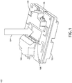
- FIG 1 illustrates two light modulated photodiode-enabled HUD monitoring devices 100 attached to a HUD display 102 (e.g., a LCOS display), in accordance with one or more embodiments of this disclosure.
- HUD displays 102 are wavelength selective switching devices, containing a multitude of reflective aluminum electrodes often arranged in an array (e.g., a 1024 by 768 grid array for XGA resolution). Each electrode is capable of reflecting a light source with modified wavelength that is dependent on the voltage applied to the specific electrode, the voltage controlled by a CMOS chip 106 or other type of circuitry.
- the HUD display 102 Upon illumination 104 by an illuminator (e.g., a high intensity lamp) upon the viewable section 108 of the HUD display 102, the HUD display 102 reflects the wavelength modified light outward towards lenses and/or a screen, where the image is displayed for a user.
- the HUD display 102 may be any type of display including but not limited to a compact HUD (CHUD).
- the shielding of the light modulated photodiode-enabled HUD monitoring device 100 obfuscates many of the components of the HUD monitoring device 100.
- Any type of display may be configured with the light modulated photodiode-enabled HUD monitoring device 100 including but not limited to the LCOS display, an LCD display, a Digital Light Processing (DLP) display, an Organic Light Emitting Diode (OLED) display, a micro-LED display, an inorganic light emitting diode display, or any other light emitting diode display. Therefore, the above description should not be interpreted as a limitation of the present disclosure, but merely as an illustration.
- FIG. 2 illustrates the light modulated photodiode-enabled HUD monitoring device 100 with the shielding removed, in accordance with one or more embodiments of this disclosure.
- Removal of the shielding of the light modulated photodiode-enabled HUD monitoring device 100 reveals the non-viewable sections 110 of the HUD display 102.
- the non-viewable sections 110 of the HUD display 102 have are constructed with the same reflective aluminum electrodes as the viewable section 108 of the HUD display 102. Because of this, a test portion 112 of the non-viewable section 110 can be used to test whether the HUD display 102 is malfunctioning (e.g., has a frozen screen or has a flipped screen).
- the light modulated photodiode-enabled HUD monitoring device 100 includes an emitter 114.
- the emitter 114 emits a pulsed signal (e.g., a control signal of emitted light) to be reflected off of a test portion 112 of the HUD display 102.
- the emitter 114 may be of any type of light emitting device used in the art including but not limited to a light emitting diode (LED) or a laser.
- the emitter 114 may be an LED configured to produce red light.
- the 114 may be a laser configured to produce blue light.
- the emitter 114 is configured to output a pulsed signal.
- light may be pulsed in a range of 100 Hz to 1 MHz.
- the light may be pulsed in a range of 1 kHz to 100 kHz.
- the light may be pulsed in a range of 5 kHz to 50 kHz.
- the light may be pulsed at approximately 10 kHz.
- a light modulated photodiode-enabled HUD monitoring device 100 that utilizes a control pulse with considerably different frequencies (e.g., 10 kHz) may still allow the discernment between the illuminator light and the control light, even if there is bleed through from the illuminator light reflected from the viewable section 108 into the test portion 112 of the HUD display 102.
- the light modulated photodiode-enabled HUD monitoring device 100 further includes a sheet polarizer 116.
- the sheet polarizer 116 linearly polarizes the pulsed signal from the emitter 114.
- the sheet polarizer 116 may be any linearizing sheet polarizer used in the art including but not limited to a Polaroid polarizer or a polyvinyl alcohol (PVA) polarizer.
- the light modulated photodiode-enabled HUD monitoring device 100 further includes a fold mirror 118.
- the fold mirror 118 directs the pulsed signal from the emitter 114 to the test portion 112 of the HUD display 102.
- the fold mirror 118 may be constructed of any material known in the art. Once the pulsed signal from the emitter 114 reaches the test portion 112 of the HUD display 102, the pulsed signal will be reflected from the display based on the voltage conditions of the aluminum electrodes (e.g., set by the CMOS chip 106) that are buried just below the surface of the HUD display 102. For example, the test portion 112 of the HUD display may be set to alternate between black and white approximately every eight to ten frames.
- the emitted pulsed signal reaches the HUD display 102 when the test portion 112 is set to reflect a white light, then an enhanced light signal will be reflected from the HUD display 102. If the emitted signal reaches the HUD display 102 when the test portion is set to black, then a reduced light signal (e.g., pulsed signal) will be reflected from the HUD display 102. The result is a toggled high/low signal that can then be used to discern if the test portion is alternating from black to white, or whether the HUD display 102 is frozen. Due to the action of the polarizer 116, the reflected pulsed signal from the test portion 112 of the HUD display 102 alternates between 0° polarization rotation and 90° polarization rotation.
- pulses signal from the emitter 114 that is reflected (i.e., directed) onto the test portion 112 by the fold mirror 118 is itself reflected by the test portion 112 back to the fold mirror 118 where the pulsed signal is then reflected to an analyzer 120.
- the analyzer is comprised of a linear polarizer that blocks or transmits the reflected pulsed signal from the fold mirror 118, depending on the polarization state.
- the pulsed signal continuing through the analyzer is detected by the detector 122.
- the detector 122 detects the emitted light signal, where it produces an electric signal that is then evaluated by circuitry within the light modulated photodiode-enabled HUD monitoring device 100.
- the detector may be any type of photodetector known in the art, including but not limited to a photodiode, metal-semiconductor-metal photodetector, phototransistor, photoconductive detector, phototube, or photomultiplier.
- the detector may be a photodiode commonly used in HUD displays. It should be known that more than one mirrors may be used in reflecting the emitted pulsed signal to the detector 122. Therefore, the above description should not be interpreted as a limitation of the present disclosure, but merely as an illustration.
- FIG. 3 illustrates a plan view of the light modulated photodiode-enabled HUD monitoring device 100 disposed upon the HUD display 102, in accordance with one or more embodiments of this disclosure.
- two light modulated photodiode-enabled HUD monitoring devices 100 are disposed upon opposite sides of the HUD display 102 (i.e., at two opposing corners), each monitoring a test portion 112 of the HUD display 102, with no aspect of either light modulated photodiode-enabled HUD monitoring device 100 blocking the viewable section 108 of the HUD display 102.
- Increasing the number of light modulated photodiode-enabled HUD monitoring devices 100 enhances the accuracy of HUD display 102 monitoring.
- the HUD display 102 is configured to have two non-viewing sections 110 (e.g., monitoring areas or photodiode areas) at opposite ends.
- Each non-viewing section 110 may be configured to have a test portion 112, with a blank portion 128 that is either unused or used for a different purpose.
- one or more test portions 112 may be monitored on an HUD display 102, with each test portion 112 monitored by a separate light modulated photodiode-enabled HUD monitoring device 100.
- an HUD display 102 may be configured to have one test portion.
- the HUD display may be configured to have four test portions. Therefore, the above description should not be interpreted as a limitation of the present disclosure, but merely as an illustration.
- FIG. 5 is a block diagram illustrating a controller of the light modulated photodiode-enabled HUD monitoring device 100, in accordance with one or more embodiments of this disclosure.
- the controller 200 provides processing functionality for the light modulated photodiode-enabled HUD monitoring device 100 and its components.
- the controller includes one or more processors 202.
- the one or more processors may include any type of processing elements, including but not limited to integrated circuits (e.g., application specific integrated circuits (ASIC), field programmable gate arrays (FPGA)).
- one processor for the light modulated photodiode-enabled HUD monitoring devices 100 may be the CMOS chip used to control the HUD display.
- the processor is a collection of circuits and components on a circuit card (e.g., a circuit card assembly (CCA) or printed circuit board (PCB)).
- the processors may also include circuitry components required to filter and modulate the incoming signals generated by the light modulated photodiode-enabled HUD monitoring devices 100 including but not limited to bandpass filters 204 a-c and rectifiers 206.
- the controller may also include resident or external memory 208 for storing data, executional code, and other resident or external memory 208 generated by the light modulated photodiode-enabled HUD monitoring devices 100.
- the controller 200 can execute one or more software programs embodied in a non-transitory computer readable medium (e.g., memory 208) that implement techniques described herein.
- the controller 200 is not limited by the materials from which it is formed or the processing mechanisms employed therein and, as such, can be implemented via semiconductor(s) and/or transistors (e.g., using electronic integrated circuit (IC) components), and so forth.
- the memory 208 can be an example of tangible, computer-readable storage medium that provides storage functionality to store various data and/or program code associated with operation of the light modulated photodiode-enabled HUD monitoring device 100 and/or controller 200, such as software programs and/or code segments, or other data to instruct the controller 200, and possibly other components of the light modulated photodiode-enabled HUD monitoring device 100, to perform the functionality described herein.
- the memory 208 can store data, such as a program of instructions for operating the controller 200, the light modulated photodiode-enabled HUD monitoring device 100, and its components.
- the memory 208 can be integral with the controller 200, can comprise stand-alone memory, or can be a combination of both. Some examples of the memory 208 can include removable and non-removable memory components, such as random-access memory (RAM), read-only memory (ROM), flash memory (e.g., a secure digital (SD) memory card, a mini-SD memory card, and/or a micro-SD memory card), solid-state drive (SSD) memory, magnetic memory, optical memory, universal serial bus (USB) memory devices, hard disk memory, external memory, and so forth.
- RAM random-access memory
- ROM read-only memory
- flash memory e.g., a secure digital (SD) memory card, a mini-SD memory card, and/or a micro-SD memory card
- SSD solid-state drive
- magnetic memory magnetic memory
- optical memory optical memory
- USB universal serial bus
- USB universal serial bus
- the controller also includes a communication interface 210.
- the communication interface 210 may be operatively configured to communicate with the light modulated photodiode-enabled HUD monitoring device 100 and its components, as well as the HUD display 102 and the data processing device for the HUD display 102.
- the communication interface 210 can be configured to retrieve data from the controller 200 or other devices (e.g., the detector 122, the emitter, and/or other components of the light modulated photodiode-enabled HUD monitoring device 100), transmit data for storage in the memory 208, retrieve data from storage in the memory 208, and so forth.
- the communication interface 210 can also be communicatively coupled with the controller 200 to facilitate data transfer between components of the light modulated photodiode-enabled HUD monitoring device 100 and the controller 212.
- the communication interface 210 may also facilitate data transfer between the light modulated photodiode-enabled HUD monitoring device 100 and the HUD display 102 and/or the processing device(s) of the HUD display.
- the communication interface 210 is described as a component of the light modulated photodiode-enabled HUD monitoring device 100, one or more components of the communication interface 210 may be implemented as external components communicatively coupled to the light modulated photodiode-enabled HUD monitoring device 100 via a wired and/or wireless connection.
- the controller 200 of the light modulated photodiode-enabled HUD monitoring device 100 further includes circuitry 300 to filter and modulate the electrical signal received from the detector 122.
- a representation of the circuitry 300 required for processing of the signal received by the detector 122 is shown in FIG. 6 .
- Components of the circuitry 300 that may be included within the light modulated photodiode-enabled HUD monitoring device 100 are enclosed within the box with the dashed border in FIG. 6 .
- the circuitry includes one or more bandpass filters 204 a-c.
- the bandpass filters 204 a-c filter out unwanted signals within the light modulated photodiode-enabled HUD monitoring device 100 (e.g., incoming electrical signals derived from the illumination from the illuminator and light from the illuminator that is reflected off of the HUD display 102).
- the light modulated photodiode-enabled HUD monitoring device 100 can more easily discern between the light emitted from the emitter 114 and other interfering light (i.e., the light modulated photodiode-enabled HUD monitoring device 100 becomes immune to the illuminator).
- the circuitry 300 includes one or more low-pass filters.
- the low-pass filter attenuates portions of the signal received by the detector 122 that have frequencies below a predetermined level (e.g., frequencies below the signal to be isolated by the light modulated photodiode-enabled HUD monitoring device 100).
- the circuitry may include a first order low-pass filter with an attenuation of 20 dB/dec.
- the circuitry 300 includes one or more high-pass filters. The high-pass filter attenuates portions of the signal received by the detector 122 that have frequencies above a predetermined level (e.g., frequencies above the signal to be isolated by the light modulated photodiode-enabled HUD monitoring device 100).
- the circuitry may include one or more second order high-pass filter with an attenuation of 40 dB/dec. It should be known that any number and type of bandpass, low-pass, and high-pass filter may be used within the circuitry 300 of the light modulated photodiode-enabled HUD monitoring device 100. Therefore, the above description should not be interpreted as a limitation of the present disclosure, but merely an illustration.
- the circuitry 300 includes a rectifier 206.
- the rectifier 206 modifies the electrical signal exiting the bandpath filter(s) 204 a-c from alternative current to direct current. The modification of the signal by the rectifier also allows the electrical signal to be analyzed and processed by downstream componentry, such as an analog-digital converter (ADC) 310.
- ADC analog-digital converter
- the rectifier 206 used in the light modulated photodiode-enabled HUD monitoring device 100 may be any type of rectifier 206 used in the art including but not limited to a full-wave rectifier, a single-phase rectifier, a three-phase rectifier, or a voltage-multiplying rectifier.
- the rectifier 206 may be a single-phase full wave rectifier.
- a pulsed, narrowly filtered (e.g., -10 kHz) and amplified signal may be successfully used by downstream componentry to discern the control signal from interfering illumination (e.g., by comparing digitized control sample signal to predicted signals and determining if the digitized control sample signal deviates from a threshold value, which may determine if the display is functioning correctly).
- the circuitry includes a voltage rail 302 supplying a voltage to the circuitry 300 and a current source 304 coupled to supply current to the voltage rail.
- the circuitry 300 further includes a current modulator 306.
- the current modulator 306 is configured to alter an aspect of the current within the circuity 300 in order to optimize the ability of the light modulated photodiode-enabled HUD monitoring device 100 to emit and detect the emitted signal and discern the signal from interfering noise (i.e., the current modulator 306 may act as a feedback loop).
- the current modulator 306 may alter the magnitude of the current used within the circuitry 300.
- the current modulator 306 may alter the frequency of the AC current within the circuitry 300.
- the current modulator 306 may alter the pulse width of the current used in the circuitry 300. Feedback modification of the current by the current modulator 306 may then increase the ability of the modulated emitted signal to be isolated and analyzed for HUD display 102 malfunctions.
- the circuitry does not include a current modulator 306.
- FIG. 7 is a graph 700 illustrating sample results from a photodiode-enabled HUD monitoring device 100.
- the X-axis of the graph represents elapsed time, whereas the Y-axis represents signal intensity.
- Four conditions are represented in the graph 700.
- the yellow and blue conditions e.g., channels one and two, respectively
- the grey conditions e.g., channels R1 and R2, respectively, represent two channels where the photodiode received signals at the same time that the illuminator was off.
- the test portion 112 of the HUD display 102 switched back and forth from 'white' and 'black' four times. This switching is manifested in the graph 700 as showing three areas where all signals have a lowered, or trough, signal (i.e., created when the test portion 112 was black) and four areas that have an increased signal (i.e., when the test portion 112 was white). Under all four conditions, a substantial difference in signal intensity was detected by the light modulated photodiode-enabled HUD monitoring device 100 when the test portion 112 switched from black to white, regardless if the illuminator was at full intensity.
- the light modulated photodiode-enabled HUD monitoring device 100 is capable of discerning a control signal from the test portion 112 without having to rely on extraneous methods to block light from the illuminator from the detector, such as by applying a gasket or glue at the boundary of the viewable section 108 and the test portion 112 to prevent bleed-through of light from the viewable section from entering the test portion 112, or by applying an optical filter, which reduces the light signal to the detector 120.
- the controller 200 may then report to the HUD display 102 or other componentry and/or device of the status of the HUD display 102.
- embodiments of the methods disclosed herein may include one or more of the steps described herein. Further, such steps may be carried out in any desired order and two or more of the steps may be carried out simultaneously with one another. Two or more of the steps disclosed herein may be combined in a single step, and in some embodiments, one or more of the steps may be carried out as two or more sub-steps. Further, other steps or sub-steps may be carried in addition to, or as substitutes to one or more of the steps disclosed herein.
Landscapes
- Physics & Mathematics (AREA)
- General Physics & Mathematics (AREA)
- Spectroscopy & Molecular Physics (AREA)
- Engineering & Computer Science (AREA)
- Optics & Photonics (AREA)
- Nonlinear Science (AREA)
- Computer Hardware Design (AREA)
- Theoretical Computer Science (AREA)
- Chemical & Material Sciences (AREA)
- Crystallography & Structural Chemistry (AREA)
- Control Of Indicators Other Than Cathode Ray Tubes (AREA)
- Photometry And Measurement Of Optical Pulse Characteristics (AREA)
Abstract
Description
- The present application claims priority to
U.S. Provisional Application Serial No. 62/965,670 filed January 24, 2020 - Head-up displays (HUD) are computer-generated displays that present data on a transparent medium (e.g., a windshield for an aircraft or a visor for a helmet), allowing the user to see the data without having to look away from their usual viewpoints. Data provided by HUDs often offer both information regarding the current status of the vehicle, such as speed as direction, as well as warnings of systems that are not in compliance. HUDs often require rapid updating of displayed data to ensure that the user has the information required for safe operation of the vehicle.
- HUDs are susceptible to malfunctioning while in use. For example, the display on a HUD may freeze up, preventing the HUD from updating the displayed data. In another example, a HUD may flip the displayed image. For these reasons, HUDs are monitored so that a malfunctioning HUD may be quickly detected and have the problem addressed. For example, a test section of a display may be dedicated to blinking between on and off states (e.g., white and black screen states), while a detector adjacent to the test section measures the rate of blinking by the test section and compares that information to an expected value. If the expected value is not detected, then the HUD will be flagged as malfunctioning. Strategies for detecting a predicted signal of a test section of a display are often compromised by light generated by the area of the display intended for viewing, which can interfere with the detection of light of the test section by the detector.
- A light-modulated photodiode-based monitor for detecting a control signal of a display is disclosed. In one or more embodiments, the light-modulated photodiode-based monitor includes an emitter configured to emit a pulsed signal. In one or more embodiments, the light-modulated photodiode-based monitor further includes a polarizer configured to linearly polarize the pulsed signal. In one or more embodiments, the light-modulated photodiode-based monitor further includes one or more fold mirrors. In one or more embodiments, the one or more fold mirrors are configured to reflect the pulsed signal from the emitter onto a test portion. In one or more embodiments, the one or more fold mirrors are configured to reflect the pulsed signal that has reflected off of the test portion. In one or more embodiments, the light-modulated photodiode-based monitor further includes an analyzer, configured to block or transmit the polarized pulse signal reflected from at least one of the fold mirror or the test portion. In one or more embodiments, the light-modulated photodiode-based monitor further includes a detector configured to receive the pulsed signal transmitted from the analyzer and convert the pulsed signal into an electrical signal. In one or more embodiments, the light-modulated photodiode-based monitor further includes a controller comprising one or more processors. In one or more embodiments, the controller is configured to receive the electrical signal from the detector. In one or more embodiments, the controller is configured to filter the electrical signal, wherein the filtered signal may be discerned from interfering signals created by an illumination of a viewable section of the display. In one or more embodiments, the controller is configured to rectify the electrical signal. In one or more embodiments, the controller is configured to determine a functional state of the display.
- In some embodiments of the light-modulated photodiode-based monitor the display may be configured as a head up display.
- In some embodiments of the light-modulated photodiode-based monitor, the display may comprise at least one of a liquid crystal on silicon display, a liquid crystal display, a digital light processing display, an organic light emitting diode display, an inorganic light emitting diode display, or a micro light emitting diode display.
- In some embodiments of the light-modulated photodiode-based monitor, the emitter is configured as a light emitting diode.
- In some embodiments of the light-modulated photodiode-based monitor, the emitter is configured as a laser.
- In some embodiments of the light-modulated photodiode-based monitor, the emitter is configured to output the pulsed signal in a range of 5 kHz to 50 kHz.
- In some embodiments of the light-modulated photodiode-based monitor, the detector comprises at least one of a photodiode, metal-semiconductor-metal photodetector, phototransistor, photoconductive detector, phototube, or photomultiplier.
- In some embodiments of the light-modulated photodiode-based monitor, the controller is further configured to report a status of the display.
- A display is also disclosed. In one or more embodiments, the display includes a test portion. In some embodiments, the display further includes a light-modulated photodiode-based monitor for detecting a control signal of the display. In one or more embodiments, the light-modulated photodiode-based monitor includes an emitter configured to emit a pulsed signal. In one or more embodiments, the light-modulated photodiode-based monitor further includes a polarizer configured to linearly polarize the pulsed signal. In one or more embodiments, the light-modulated photodiode-based monitor further includes one or more fold mirrors. In one or more embodiments, the one or more fold mirrors are configured to reflect the pulsed signal from the emitter onto the test portion. In one or more embodiments, the one or more fold mirrors are configured to reflect the pulsed signal that has reflected off of the test portion. In one or more embodiments, the light-modulated photodiode-based monitor further includes an analyzer, configured to block or transmit the polarized pulse signal reflected from at least one of the fold mirror or the test portion. In one or more embodiments, the light-modulated photodiode-based monitor further includes a detector configured to receive the pulsed signal transmitted from the analyzer and convert the pulsed signal into an electrical signal. In one or more embodiments, the light-modulated photodiode-based monitor further includes a controller comprising one or more processors. In one or more embodiments, the controller is configured to receive the electrical signal from the detector. In one or more embodiments, the controller is configured to filter the electrical signal, wherein the filtered signal may be discerned from interfering signals created by an illumination of a viewable section of the display. In one or more embodiments, the controller is configured to rectify the electrical signal. In one or more embodiments, the controller is configured to determine a functional state of the display.
- In some embodiments of the display, the display may be configured as a head up display.
- In some embodiments of the display, the display may comprise at least one of a liquid crystal on silicon display, a liquid crystal display, a digital light processing display, an organic light emitting diode display, an inorganic light emitting diode display, or a micro light emitting diode display.
- In some embodiments of the display, the emitter is configured as a light emitting diode.
- In some embodiments of the display, the emitter is configured as a laser.
- In some embodiments of the display, the emitter is configured to output the pulsed signal in a range of 5 kHz to 50 kHz.
- In some embodiments of the display, the detector comprises at least one of a photodiode, metal-semiconductor-metal photodetector, phototransistor, photoconductive detector, phototube, or photomultiplier.
- In some embodiments of the display, the controller is further configured to report a status of the display.
- This Summary is provided solely as an introduction to subject matter that is fully described in the Detailed Description and Drawings. The Summary should not be considered to describe essential features nor be used to determine the scope of the Claims. Moreover, it is to be understood that both the foregoing Summary and the following Detailed Description are example and explanatory only and are not necessarily restrictive of the subject matter claimed.
- The detailed description is described with reference to the accompanying figures. The use of the same reference numbers in different instances in the description and the figures may indicate similar or identical items. Various embodiments or examples ("examples") of the present disclosure are disclosed in the following detailed description and the accompanying drawings. The drawings are not necessarily to scale. In general, operations of disclosed processes may be performed in an arbitrary order, unless otherwise provided in the claims.
-
FIG. 1 is an illustration of a light modulated photodiode-enabled HUD monitoring device attached to a HUD display, in accordance with one or more embodiments of this disclosure. -
FIG. 2 is an illustration of a light modulated photodiode-enabled HUD monitoring device with the shielding removed, in accordance with one or more embodiments of this disclosure. -
FIG. 3 is a plan view of an illustration of the light modulated photodiode-enabled HUD monitoring device disposed upon the HUD display, in accordance with one or more embodiments of this disclosure. -
FIG. 4 is an illustration of the layout of a HUD display, in accordance with one or more embodiments of this disclosure. -
FIG. 5 is a block diagram illustrating a controller of the light modulated photodiode-enabled HUD monitoring device, in accordance with one or more embodiments of this disclosure. -
FIG. 6 is a schematic illustration of circuitry for processing an electrical signal received from a detector, in accordance with one or more embodiments of this disclosure. -
FIG. 7 is a graph illustrating sample results from a photodiode-enabled HUD monitoring device. in accordance with one or more embodiments of this disclosure. - Before explaining one or more embodiments of the disclosure in detail, it is to be understood that the embodiments are not limited in their application to the details of construction and the arrangement of the components or steps or methodologies set forth in the following description or illustrated in the drawings. In the following detailed description of embodiments, numerous specific details may be set forth in order to provide a more thorough understanding of the disclosure. However, it will be apparent to one of ordinary skill in the art having the benefit of the instant disclosure that the embodiments disclosed herein may be practiced without some of these specific details. In other instances, well-known features may not be described in detail to avoid unnecessarily complicating the instant disclosure.
- As used herein a letter following a reference numeral is intended to reference an embodiment of the feature or element that may be similar, but not necessarily identical, to a previously described element or feature bearing the same reference numeral (e.g., 1, 1a, 1b). Such shorthand notations are used for purposes of convenience only and should not be construed to limit the disclosure in any way unless expressly stated to the contrary.
- Further, unless expressly stated to the contrary, "or" refers to an inclusive or and not to an exclusive or. For example, a condition A or B is satisfied by anyone of the following: A is true (or present) and B is false (or not present), A is false (or not present) and B is true (or present), and both A and B are true (or present).
- In addition, use of "a" or "an" may be employed to describe elements and components of embodiments disclosed herein. This is done merely for convenience and "a" and "an" are intended to include "one" or "at least one," and the singular also includes the plural unless it is obvious that it is meant otherwise.
- Finally, as used herein any reference to "one embodiment" or "some embodiments" means that a particular element, feature, structure, or characteristic described in connection with the embodiment is included in at least one embodiment disclosed herein. The appearances of the phrase "in some embodiments" in various places in the specification are not necessarily all referring to the same embodiment, and embodiments may include one or more of the features expressly described or inherently present herein, or any combination of sub-combination of two or more such features, along with any other features which may not necessarily be expressly described or inherently present in the instant disclosure.
- A light modulated photodiode-enabled HUD monitoring device is disclosed. In implementations, the light modulated photodiode-enabled HUD monitoring device tests the display of the HUD (e.g., of a liquid crystal on silicon (LCOS) display) by pulsing an LED onto a test section of the HUD display at a high rate that can be distinguished from the frequency of the illuminator. The signal reflected off of the LCOS is received by a detector, creating an electrical signal which can then be filtered and converted to a digital input and tested to see if the received signal matches the expected signal of a properly operating HUD.
- The advantages of the light modulated photodiode-enabled HUD monitoring device over a conventional HUD monitoring device include a reduced requirement for preventing light from the display area that is intended for viewing from leaking into the test area. Conventional HUD monitoring devices require strict separation of the viewing area of the display from the test area of the display. This often requires the use and utilization of gaskets and/or adhesives under narrow tolerance specifications that can result in high failure rates. Optical filters may also be used to separate interfering light signals. However, the same optical filters reduce the control light signal to the detector, reducing the robustness of the monitoring device and increasing failure rates. The light modulated photodiode-enabled HUD monitoring device of this disclosure solves the problem of light interference by creating a control signal and detector arrangement that is immune to light from the illuminator.
- In some embodiments, the photodiode-based HUD monitoring device is attached to an HUD display.
FIG 1 , illustrates two light modulated photodiode-enabledHUD monitoring devices 100 attached to a HUD display 102 (e.g., a LCOS display), in accordance with one or more embodiments of this disclosure. HUD displays 102 are wavelength selective switching devices, containing a multitude of reflective aluminum electrodes often arranged in an array (e.g., a 1024 by 768 grid array for XGA resolution). Each electrode is capable of reflecting a light source with modified wavelength that is dependent on the voltage applied to the specific electrode, the voltage controlled by aCMOS chip 106 or other type of circuitry. Uponillumination 104 by an illuminator (e.g., a high intensity lamp) upon theviewable section 108 of theHUD display 102, theHUD display 102 reflects the wavelength modified light outward towards lenses and/or a screen, where the image is displayed for a user. TheHUD display 102 may be any type of display including but not limited to a compact HUD (CHUD). - In
FIG. 1 , the shielding of the light modulated photodiode-enabledHUD monitoring device 100 obfuscates many of the components of theHUD monitoring device 100. Any type of display may be configured with the light modulated photodiode-enabledHUD monitoring device 100 including but not limited to the LCOS display, an LCD display, a Digital Light Processing (DLP) display, an Organic Light Emitting Diode (OLED) display, a micro-LED display, an inorganic light emitting diode display, or any other light emitting diode display. Therefore, the above description should not be interpreted as a limitation of the present disclosure, but merely as an illustration. -
FIG. 2 illustrates the light modulated photodiode-enabledHUD monitoring device 100 with the shielding removed, in accordance with one or more embodiments of this disclosure. Removal of the shielding of the light modulated photodiode-enabledHUD monitoring device 100 reveals thenon-viewable sections 110 of theHUD display 102. Thenon-viewable sections 110 of theHUD display 102 have are constructed with the same reflective aluminum electrodes as theviewable section 108 of theHUD display 102. Because of this, atest portion 112 of thenon-viewable section 110 can be used to test whether theHUD display 102 is malfunctioning (e.g., has a frozen screen or has a flipped screen). - In some embodiments, the light modulated photodiode-enabled
HUD monitoring device 100 includes anemitter 114. Theemitter 114 emits a pulsed signal (e.g., a control signal of emitted light) to be reflected off of atest portion 112 of theHUD display 102. Theemitter 114 may be of any type of light emitting device used in the art including but not limited to a light emitting diode (LED) or a laser. For example, theemitter 114 may be an LED configured to produce red light. In another example, the 114 may be a laser configured to produce blue light. - In some embodiments, the
emitter 114 is configured to output a pulsed signal. For example, light may be pulsed in a range of 100 Hz to 1 MHz. In another example, the light may be pulsed in a range of 1 kHz to 100 kHz. In another example, the light may be pulsed in a range of 5 kHz to 50 kHz. For instance, the light may be pulsed at approximately 10 kHz. Since light from an LCOS illuminator is typically pulse-width modulated at 120 Hz for brightness control, a light modulated photodiode-enabledHUD monitoring device 100 that utilizes a control pulse with considerably different frequencies (e.g., 10 kHz) may still allow the discernment between the illuminator light and the control light, even if there is bleed through from the illuminator light reflected from theviewable section 108 into thetest portion 112 of theHUD display 102. - In some embodiments, the light modulated photodiode-enabled
HUD monitoring device 100 further includes asheet polarizer 116. Thesheet polarizer 116 linearly polarizes the pulsed signal from theemitter 114. Thesheet polarizer 116 may be any linearizing sheet polarizer used in the art including but not limited to a Polaroid polarizer or a polyvinyl alcohol (PVA) polarizer. - In some embodiments, the light modulated photodiode-enabled
HUD monitoring device 100 further includes afold mirror 118. Thefold mirror 118 directs the pulsed signal from theemitter 114 to thetest portion 112 of theHUD display 102. Thefold mirror 118 may be constructed of any material known in the art. Once the pulsed signal from theemitter 114 reaches thetest portion 112 of theHUD display 102, the pulsed signal will be reflected from the display based on the voltage conditions of the aluminum electrodes (e.g., set by the CMOS chip 106) that are buried just below the surface of theHUD display 102. For example, thetest portion 112 of the HUD display may be set to alternate between black and white approximately every eight to ten frames. (i.e., that is, set so that a light that illuminates thetest portion 112 will reflect either a relatively intense light signal, or a reduced light signal). If the emitted pulsed signal reaches theHUD display 102 when thetest portion 112 is set to reflect a white light, then an enhanced light signal will be reflected from theHUD display 102. If the emitted signal reaches theHUD display 102 when the test portion is set to black, then a reduced light signal (e.g., pulsed signal) will be reflected from theHUD display 102. The result is a toggled high/low signal that can then be used to discern if the test portion is alternating from black to white, or whether theHUD display 102 is frozen. Due to the action of thepolarizer 116, the reflected pulsed signal from thetest portion 112 of theHUD display 102 alternates between 0° polarization rotation and 90° polarization rotation. - In some embodiments, pulses signal from the
emitter 114 that is reflected (i.e., directed) onto thetest portion 112 by thefold mirror 118 is itself reflected by thetest portion 112 back to thefold mirror 118 where the pulsed signal is then reflected to ananalyzer 120. The analyzer is comprised of a linear polarizer that blocks or transmits the reflected pulsed signal from thefold mirror 118, depending on the polarization state. In some embodiments, the pulsed signal continuing through the analyzer is detected by thedetector 122. Thedetector 122 detects the emitted light signal, where it produces an electric signal that is then evaluated by circuitry within the light modulated photodiode-enabledHUD monitoring device 100. The detector may be any type of photodetector known in the art, including but not limited to a photodiode, metal-semiconductor-metal photodetector, phototransistor, photoconductive detector, phototube, or photomultiplier. For example, the detector may be a photodiode commonly used in HUD displays. It should be known that more than one mirrors may be used in reflecting the emitted pulsed signal to thedetector 122. Therefore, the above description should not be interpreted as a limitation of the present disclosure, but merely as an illustration. - In some embodiments, the
non-viewable sections 110 of theHUD display 102 may contain more than onetest portion 112.FIG. 3 illustrates a plan view of the light modulated photodiode-enabledHUD monitoring device 100 disposed upon theHUD display 102, in accordance with one or more embodiments of this disclosure. In this embodiment, two light modulated photodiode-enabledHUD monitoring devices 100 are disposed upon opposite sides of the HUD display 102 (i.e., at two opposing corners), each monitoring atest portion 112 of theHUD display 102, with no aspect of either light modulated photodiode-enabledHUD monitoring device 100 blocking theviewable section 108 of theHUD display 102. Increasing the number of light modulated photodiode-enabledHUD monitoring devices 100 enhances the accuracy ofHUD display 102 monitoring. - The layout of the
HUD display 102 withmultiple test portions 112 are described further inFIG. 4 . As aforementioned, in embodiments, theHUD display 102 is configured to have two non-viewing sections 110 (e.g., monitoring areas or photodiode areas) at opposite ends. Eachnon-viewing section 110 may be configured to have atest portion 112, with ablank portion 128 that is either unused or used for a different purpose. It should be known that one ormore test portions 112, may be monitored on anHUD display 102, with eachtest portion 112 monitored by a separate light modulated photodiode-enabledHUD monitoring device 100. For example, anHUD display 102 may be configured to have one test portion. In another example, the HUD display may be configured to have four test portions. Therefore, the above description should not be interpreted as a limitation of the present disclosure, but merely as an illustration. - In some embodiments, the activities of the
emitter 114,detector 122, and other components of the light modulated photodiode-enabledHUD monitoring device 100, as well as the methods to analyze electrical signals received from thedetector 122 are controlled by acontroller 200.FIG. 5 is a block diagram illustrating a controller of the light modulated photodiode-enabledHUD monitoring device 100, in accordance with one or more embodiments of this disclosure. Thecontroller 200 provides processing functionality for the light modulated photodiode-enabledHUD monitoring device 100 and its components. The controller includes one ormore processors 202. The one or more processors may include any type of processing elements, including but not limited to integrated circuits (e.g., application specific integrated circuits (ASIC), field programmable gate arrays (FPGA)). For example, one processor for the light modulated photodiode-enabledHUD monitoring devices 100 may be the CMOS chip used to control the HUD display. In another example, the processor is a collection of circuits and components on a circuit card (e.g., a circuit card assembly (CCA) or printed circuit board (PCB)). The processors may also include circuitry components required to filter and modulate the incoming signals generated by the light modulated photodiode-enabledHUD monitoring devices 100 including but not limited tobandpass filters 204 a-c andrectifiers 206. - The controller may also include resident or
external memory 208 for storing data, executional code, and other resident orexternal memory 208 generated by the light modulated photodiode-enabledHUD monitoring devices 100. Thecontroller 200 can execute one or more software programs embodied in a non-transitory computer readable medium (e.g., memory 208) that implement techniques described herein. In some embodiments, thecontroller 200 is not limited by the materials from which it is formed or the processing mechanisms employed therein and, as such, can be implemented via semiconductor(s) and/or transistors (e.g., using electronic integrated circuit (IC) components), and so forth. - The
memory 208 can be an example of tangible, computer-readable storage medium that provides storage functionality to store various data and/or program code associated with operation of the light modulated photodiode-enabledHUD monitoring device 100 and/orcontroller 200, such as software programs and/or code segments, or other data to instruct thecontroller 200, and possibly other components of the light modulated photodiode-enabledHUD monitoring device 100, to perform the functionality described herein. Thus, thememory 208 can store data, such as a program of instructions for operating thecontroller 200, the light modulated photodiode-enabledHUD monitoring device 100, and its components. It should be noted that while asingle memory 208 is described, a wide variety of types of combinations of memory (e.g., tangible, non-transitory memory) may be employed. Thememory 208 can be integral with thecontroller 200, can comprise stand-alone memory, or can be a combination of both. Some examples of thememory 208 can include removable and non-removable memory components, such as random-access memory (RAM), read-only memory (ROM), flash memory (e.g., a secure digital (SD) memory card, a mini-SD memory card, and/or a micro-SD memory card), solid-state drive (SSD) memory, magnetic memory, optical memory, universal serial bus (USB) memory devices, hard disk memory, external memory, and so forth. In some embodiments, thecontroller 200 and/or the light modulated photodiode-enabledHUD monitoring device 100 does not include a memory. - The controller also includes a
communication interface 210. Thecommunication interface 210 may be operatively configured to communicate with the light modulated photodiode-enabledHUD monitoring device 100 and its components, as well as theHUD display 102 and the data processing device for theHUD display 102. For example, thecommunication interface 210 can be configured to retrieve data from thecontroller 200 or other devices (e.g., thedetector 122, the emitter, and/or other components of the light modulated photodiode-enabled HUD monitoring device 100), transmit data for storage in thememory 208, retrieve data from storage in thememory 208, and so forth. Thecommunication interface 210 can also be communicatively coupled with thecontroller 200 to facilitate data transfer between components of the light modulated photodiode-enabledHUD monitoring device 100 and the controller 212. Thecommunication interface 210 may also facilitate data transfer between the light modulated photodiode-enabledHUD monitoring device 100 and theHUD display 102 and/or the processing device(s) of the HUD display. - It should be noted that while the
communication interface 210 is described as a component of the light modulated photodiode-enabledHUD monitoring device 100, one or more components of thecommunication interface 210 may be implemented as external components communicatively coupled to the light modulated photodiode-enabledHUD monitoring device 100 via a wired and/or wireless connection. - In some embodiments, the
controller 200 of the light modulated photodiode-enabledHUD monitoring device 100 further includescircuitry 300 to filter and modulate the electrical signal received from thedetector 122. A representation of thecircuitry 300 required for processing of the signal received by thedetector 122 is shown inFIG. 6 . Components of thecircuitry 300 that may be included within the light modulated photodiode-enabledHUD monitoring device 100 are enclosed within the box with the dashed border inFIG. 6 . In embodiments, the circuitry includes one or morebandpass filters 204 a-c. Thebandpass filters 204 a-c filter out unwanted signals within the light modulated photodiode-enabled HUD monitoring device 100 (e.g., incoming electrical signals derived from the illumination from the illuminator and light from the illuminator that is reflected off of the HUD display 102). By filtering out the interfering electrical signals that originated as light from the viewable section of theHUD display 102, the light modulated photodiode-enabledHUD monitoring device 100 can more easily discern between the light emitted from theemitter 114 and other interfering light (i.e., the light modulated photodiode-enabledHUD monitoring device 100 becomes immune to the illuminator). - In some embodiments, the
circuitry 300 includes one or more low-pass filters. The low-pass filter attenuates portions of the signal received by thedetector 122 that have frequencies below a predetermined level (e.g., frequencies below the signal to be isolated by the light modulated photodiode-enabled HUD monitoring device 100). For example, the circuitry may include a first order low-pass filter with an attenuation of 20 dB/dec. In some embodiments, thecircuitry 300 includes one or more high-pass filters. The high-pass filter attenuates portions of the signal received by thedetector 122 that have frequencies above a predetermined level (e.g., frequencies above the signal to be isolated by the light modulated photodiode-enabled HUD monitoring device 100). For example, the circuitry may include one or more second order high-pass filter with an attenuation of 40 dB/dec. It should be known that any number and type of bandpass, low-pass, and high-pass filter may be used within thecircuitry 300 of the light modulated photodiode-enabledHUD monitoring device 100. Therefore, the above description should not be interpreted as a limitation of the present disclosure, but merely an illustration. - In some embodiments, the
circuitry 300 includes arectifier 206. Therectifier 206 modifies the electrical signal exiting the bandpath filter(s) 204 a-c from alternative current to direct current. The modification of the signal by the rectifier also allows the electrical signal to be analyzed and processed by downstream componentry, such as an analog-digital converter (ADC) 310. Therectifier 206 used in the light modulated photodiode-enabledHUD monitoring device 100 may be any type ofrectifier 206 used in the art including but not limited to a full-wave rectifier, a single-phase rectifier, a three-phase rectifier, or a voltage-multiplying rectifier. For example, therectifier 206 may be a single-phase full wave rectifier. Through the use ofbandpass filters 204 a-c andrectifiers 206, along with other signal amplifying components of the circuitry, a pulsed, narrowly filtered (e.g., -10 kHz) and amplified signal may be successfully used by downstream componentry to discern the control signal from interfering illumination (e.g., by comparing digitized control sample signal to predicted signals and determining if the digitized control sample signal deviates from a threshold value, which may determine if the display is functioning correctly). - In some embodiments, the circuitry includes a
voltage rail 302 supplying a voltage to thecircuitry 300 and acurrent source 304 coupled to supply current to the voltage rail. In some embodiments, thecircuitry 300 further includes acurrent modulator 306. Thecurrent modulator 306 is configured to alter an aspect of the current within thecircuity 300 in order to optimize the ability of the light modulated photodiode-enabledHUD monitoring device 100 to emit and detect the emitted signal and discern the signal from interfering noise (i.e., thecurrent modulator 306 may act as a feedback loop). For example, thecurrent modulator 306 may alter the magnitude of the current used within thecircuitry 300. In another example, thecurrent modulator 306 may alter the frequency of the AC current within thecircuitry 300. In another example, thecurrent modulator 306 may alter the pulse width of the current used in thecircuitry 300. Feedback modification of the current by thecurrent modulator 306 may then increase the ability of the modulated emitted signal to be isolated and analyzed forHUD display 102 malfunctions. In some embodiments, the circuitry does not include acurrent modulator 306. -
FIG. 7 is agraph 700 illustrating sample results from a photodiode-enabledHUD monitoring device 100. The X-axis of the graph represents elapsed time, whereas the Y-axis represents signal intensity. Four conditions are represented in thegraph 700. The yellow and blue conditions (e.g., channels one and two, respectively) represent two channels where the photodiode received signals at the same time that the illuminator was operating at maximum brightness. The grey conditions (e.g., channels R1 and R2, respectively, represent two channels where the photodiode received signals at the same time that the illuminator was off. During the sampled time, thetest portion 112 of theHUD display 102 switched back and forth from 'white' and 'black' four times. This switching is manifested in thegraph 700 as showing three areas where all signals have a lowered, or trough, signal (i.e., created when thetest portion 112 was black) and four areas that have an increased signal (i.e., when thetest portion 112 was white). Under all four conditions, a substantial difference in signal intensity was detected by the light modulated photodiode-enabledHUD monitoring device 100 when thetest portion 112 switched from black to white, regardless if the illuminator was at full intensity. This result confirms that the light modulated photodiode-enabledHUD monitoring device 100 is capable of discerning a control signal from thetest portion 112 without having to rely on extraneous methods to block light from the illuminator from the detector, such as by applying a gasket or glue at the boundary of theviewable section 108 and thetest portion 112 to prevent bleed-through of light from the viewable section from entering thetest portion 112, or by applying an optical filter, which reduces the light signal to thedetector 120. Once the determination by the controller 200 (e.g., via the circuitry 300) of the functional state of theHUD display 102 is determined (e.g., working properly or improperly), the controller may then report to theHUD display 102 or other componentry and/or device of the status of theHUD display 102. - It is to be understood that embodiments of the methods disclosed herein may include one or more of the steps described herein. Further, such steps may be carried out in any desired order and two or more of the steps may be carried out simultaneously with one another. Two or more of the steps disclosed herein may be combined in a single step, and in some embodiments, one or more of the steps may be carried out as two or more sub-steps. Further, other steps or sub-steps may be carried in addition to, or as substitutes to one or more of the steps disclosed herein.
- Although inventive concepts have been described with reference to the embodiments illustrated in the attached drawing figures, equivalents may be employed and substitutions made herein without departing from the scope of the claims. Components illustrated and described herein are merely examples of a system/device and components that may be used to implement embodiments of the inventive concepts and may be replaced with other devices and components without departing from the scope of the claims. Furthermore, any dimensions, degrees, and/or numerical ranges provided herein are to be understood as non-limiting examples unless otherwise specified in the claims.
Claims (15)
- A light-modulated photodiode-based monitor (100) for detecting a control signal of a display comprising:an emitter (114), configured to emit a pulsed signal;a polarizer (116) configured to linearly polarize the pulsed signal;one or more fold mirrors (118), configured to perform at least one of:reflecting the pulsed signal from the emitter onto a test portion (112); orreflecting the pulsed signal that has reflected off of the test portion (112);an analyzer (120), configured to block or transmit the polarized pulse signal reflected from at least one of the fold mirror or the test portion;a detector (122), configured to receive the pulsed signal transmitted from the analyzer and convert the pulsed signal into an electrical signal; anda controller (200) comprising one or more processors, and configured to perform the steps of:receiving the electrical signal from the detector;filtering the electrical signal, wherein the filtered signal may be discerned from interfering signals created by an illumination of a viewable section of the display;rectifying the electrical signal; anddetermining a functional state of the display.
- The light-modulated photodiode-based monitor of claim 1, wherein the display may be configured as a head up display (102).
- The light-modulated photodiode-based monitor of claim 1 or 2, wherein the display may comprise at least one of a liquid crystal on silicon display, a liquid crystal display, a digital light processing display, an organic light emitting diode display, an inorganic light emitting diode display, or a micro light emitting diode display.
- The light-modulated photodiode-based monitor of any preceding claim, wherein the emitter (114) is configured as a light emitting diode.
- The light-modulated photodiode-based monitor of any of claims 1-3, wherein the emitter (114) is configured as a laser.
- The light-modulated photodiode-based monitor of any preceding claim, wherein the emitter (114) is configured to output the pulsed signal in a range of 5 kHz to 50 kHz.
- The light-modulated photodiode-based monitor of any preceding claim, wherein the detector (122) comprises at least one of a photodiode, metal-semiconductor-metal photodetector, phototransistor, photoconductive detector, phototube, or photomultiplier.
- The light-modulated photodiode-based monitor of any preceding claim, wherein the controller (200) is further configured to report a status of the display.
- A display comprising:a test portion (112); anda light-modulated photodiode-based monitor (100) for detecting a control signal of the display comprising:an emitter (114), configured to emit a pulsed signal;a polarizer (116) configured to linearly polarize the pulsed signal;one or more fold mirrors (118), configured to perform at least one of:reflecting the pulsed signal from the emitter onto the test portion; orreflect the pulsed signal that has reflected off of the test portion,an analyzer (120), configured to block or transmit the polarized pulsed signal reflected from at least one of the fold mirror or the test portion,a detector (122), configured to receive the pulsed signal transmitted from the analyzer and convert the pulsed signal into an electrical signal,one or more processors; anda controller (200), configured to perform the steps of:receiving the electrical signal from the detector,filtering the electrical signal, wherein the filtered signal may be discerned from interfering signals created by an illumination of a viewable section of the display,rectifying the electrical signal, andcomparing the electrical signal to a threshold to determine if the display is functioning properly.
- The display of claim 9, wherein the display may be configured as a head up display (102).
- The display of claim 9 or 10, wherein the display may comprise at least one of a liquid crystal on silicon display, a liquid crystal display, a digital light processing display, an organic light emitting diode display, an inorganic light emitting diode display, or a micro light emitting diode display.
- The display of any of claims 9-11, wherein the emitter (114) is configured as a light emitting diode.
- The display of any of claims 9-11, wherein the emitter (114) is configured as a laser.
- The display of any of claims 9-13, wherein the emitter (114) is configured to output the pulsed signal in a range of 5 kHz to 50 kHz.
- The display of any of claims 9-14, wherein the detector (122) comprises at least one of a photodiode, metal-semiconductor-metal photodetector, phototransistor, photoconductive detector, phototube, or photomultiplier.
Applications Claiming Priority (2)
| Application Number | Priority Date | Filing Date | Title |
|---|---|---|---|
| US202062965670P | 2020-01-24 | 2020-01-24 | |
| US17/152,933 US11373567B2 (en) | 2020-01-24 | 2021-01-20 | Light modulated photodiode-based display monitor system |
Publications (2)
| Publication Number | Publication Date |
|---|---|
| EP3855238A1 true EP3855238A1 (en) | 2021-07-28 |
| EP3855238B1 EP3855238B1 (en) | 2024-04-10 |
Family
ID=74236091
Family Applications (1)
| Application Number | Title | Priority Date | Filing Date |
|---|---|---|---|
| EP21153316.1A Active EP3855238B1 (en) | 2020-01-24 | 2021-01-25 | Light modulated photodiode-based display monitor system |
Country Status (2)
| Country | Link |
|---|---|
| US (1) | US11373567B2 (en) |
| EP (1) | EP3855238B1 (en) |
Families Citing this family (1)
| Publication number | Priority date | Publication date | Assignee | Title |
|---|---|---|---|---|
| KR102663270B1 (en) * | 2022-01-25 | 2024-05-07 | 현대모비스 주식회사 | Device and Method for Detecting Screen Freeze Error of Display of Vehicle |
Citations (3)
| Publication number | Priority date | Publication date | Assignee | Title |
|---|---|---|---|---|
| WO2014091435A1 (en) * | 2012-12-13 | 2014-06-19 | Primesense Ltd. | Detecting failure of scanning mirror |
| US20180160087A1 (en) * | 2016-12-01 | 2018-06-07 | Panasonic Automotive Systems Company Of America, Division Of Panasonic Corporation Of North America | Hud image optimization through software control of displayed graphics |
| US10247943B1 (en) * | 2015-05-18 | 2019-04-02 | Rockwell Collins, Inc. | Head up display (HUD) using a light pipe |
Family Cites Families (10)
| Publication number | Priority date | Publication date | Assignee | Title |
|---|---|---|---|---|
| EP1763864B1 (en) | 2004-06-04 | 2008-12-24 | Jakob Hatteland Display AS | Picture freeze detector |
| US7834867B2 (en) * | 2006-04-11 | 2010-11-16 | Microvision, Inc. | Integrated photonics module and devices using integrated photonics modules |
| JP5988074B2 (en) * | 2012-01-27 | 2016-09-07 | 日本精機株式会社 | Vehicle head-up display device and self-check method thereof |
| DE102012014352A1 (en) | 2012-07-20 | 2014-05-15 | Audi Ag | Display device of a motor vehicle and method for operating such a display device |
| WO2016117362A1 (en) * | 2015-01-19 | 2016-07-28 | 三菱電機株式会社 | Image display device and display correction method |
| US20170188023A1 (en) | 2015-12-26 | 2017-06-29 | Intel Corporation | Method and system of measuring on-screen transitions to determine image processing performance |
| JP2018082395A (en) | 2016-11-18 | 2018-05-24 | パナソニックIpマネジメント株式会社 | Imaging apparatus state monitor, imaging apparatus state monitoring method, and program |
| DE102017200895A1 (en) | 2017-01-20 | 2018-07-26 | Zf Friedrichshafen Ag | Method and device for checking a display device for a vehicle and display device for a vehicle |
| US11284062B2 (en) | 2017-09-05 | 2022-03-22 | Texas Instruments Incorporated | Automotive display validation |
| GB2568296B (en) | 2017-11-13 | 2022-06-01 | Bae Systems Plc | Integrity monitoring |
-
2021
- 2021-01-20 US US17/152,933 patent/US11373567B2/en active Active
- 2021-01-25 EP EP21153316.1A patent/EP3855238B1/en active Active
Patent Citations (3)
| Publication number | Priority date | Publication date | Assignee | Title |
|---|---|---|---|---|
| WO2014091435A1 (en) * | 2012-12-13 | 2014-06-19 | Primesense Ltd. | Detecting failure of scanning mirror |
| US10247943B1 (en) * | 2015-05-18 | 2019-04-02 | Rockwell Collins, Inc. | Head up display (HUD) using a light pipe |
| US20180160087A1 (en) * | 2016-12-01 | 2018-06-07 | Panasonic Automotive Systems Company Of America, Division Of Panasonic Corporation Of North America | Hud image optimization through software control of displayed graphics |
Also Published As
| Publication number | Publication date |
|---|---|
| US11373567B2 (en) | 2022-06-28 |
| EP3855238B1 (en) | 2024-04-10 |
| US20210233444A1 (en) | 2021-07-29 |
Similar Documents
| Publication | Publication Date | Title |
|---|---|---|
| EP3182158B1 (en) | Ranging apparatus | |
| EP3964867B1 (en) | Laser radar, and anti-jamming method therefor | |
| US11368214B2 (en) | Automated system for link health assessment in fiber optic networks | |
| CN110720048B (en) | Operating method and control unit for lidar system, lidar system and operating equipment | |
| US20210328404A1 (en) | Light-source drive device and light-emitting device | |
| US11373567B2 (en) | Light modulated photodiode-based display monitor system | |
| US11860232B2 (en) | Photodetection sensor for monitoring and fault detection | |
| CN111262621B (en) | Method for performing automatic recovery from system hardware failure and optical communication module using the same | |
| CN108844718A (en) | A kind of laser scanning projection's device, equipment and detection method | |
| JP2021506191A (en) | Integrity monitoring | |
| US9083946B2 (en) | System to detect failed pixels in a sensor array | |
| CN107765117B (en) | A kind of test device and method of optical module self-healing | |
| WO2019227975A1 (en) | Control system of laser projector, terminal and control method of laser projector | |
| KR20170024789A (en) | Apparatus for detecting illumination and method thereof | |
| JP6750641B2 (en) | Judgment device, multi-optical axis photoelectric sensor, control method of judgment device, information processing program, and recording medium | |
| CN113126067A (en) | Laser safety circuit and laser safety equipment | |
| JP6796267B2 (en) | Anomaly detection device, projection device, anomaly detection method, and program | |
| CN113196597B (en) | Lighting module including enhanced eye safety features | |
| JPH02144714A (en) | Optical touch panel apparatus | |
| KR101511224B1 (en) | CCTV camera for display with realtime change operating state | |
| US20170263168A1 (en) | Apparatus, method, and non-transitory medium storing program for image display | |
| TWI822279B (en) | Detection method | |
| JPS6115421A (en) | Photoelectric switch | |
| JP2013192067A (en) | Photoelectric switch and mutual interference prevention method | |
| WO2025061840A1 (en) | Point spread function estimation system and method |
Legal Events
| Date | Code | Title | Description |
|---|---|---|---|
| PUAI | Public reference made under article 153(3) epc to a published international application that has entered the european phase |
Free format text: ORIGINAL CODE: 0009012 |
|
| STAA | Information on the status of an ep patent application or granted ep patent |
Free format text: STATUS: THE APPLICATION HAS BEEN PUBLISHED |
|
| AK | Designated contracting states |
Kind code of ref document: A1 Designated state(s): AL AT BE BG CH CY CZ DE DK EE ES FI FR GB GR HR HU IE IS IT LI LT LU LV MC MK MT NL NO PL PT RO RS SE SI SK SM TR |
|
| STAA | Information on the status of an ep patent application or granted ep patent |
Free format text: STATUS: REQUEST FOR EXAMINATION WAS MADE |
|
| 17P | Request for examination filed |
Effective date: 20220128 |
|
| RBV | Designated contracting states (corrected) |
Designated state(s): AL AT BE BG CH CY CZ DE DK EE ES FI FR GB GR HR HU IE IS IT LI LT LU LV MC MK MT NL NO PL PT RO RS SE SI SK SM TR |
|
| RIC1 | Information provided on ipc code assigned before grant |
Ipc: G02F 1/13 20060101ALI20230920BHEP Ipc: G02B 27/01 20060101AFI20230920BHEP |
|
| GRAP | Despatch of communication of intention to grant a patent |
Free format text: ORIGINAL CODE: EPIDOSNIGR1 |
|
| STAA | Information on the status of an ep patent application or granted ep patent |
Free format text: STATUS: GRANT OF PATENT IS INTENDED |
|
| INTG | Intention to grant announced |
Effective date: 20231115 |
|
| GRAS | Grant fee paid |
Free format text: ORIGINAL CODE: EPIDOSNIGR3 |
|
| GRAA | (expected) grant |
Free format text: ORIGINAL CODE: 0009210 |
|
| STAA | Information on the status of an ep patent application or granted ep patent |
Free format text: STATUS: THE PATENT HAS BEEN GRANTED |
|
| AK | Designated contracting states |
Kind code of ref document: B1 Designated state(s): AL AT BE BG CH CY CZ DE DK EE ES FI FR GB GR HR HU IE IS IT LI LT LU LV MC MK MT NL NO PL PT RO RS SE SI SK SM TR |
|
| REG | Reference to a national code |
Ref country code: GB Ref legal event code: FG4D |
|
| REG | Reference to a national code |
Ref country code: CH Ref legal event code: EP |
|
| REG | Reference to a national code |
Ref country code: DE Ref legal event code: R096 Ref document number: 602021011441 Country of ref document: DE |
|
| REG | Reference to a national code |
Ref country code: IE Ref legal event code: FG4D |
|
| REG | Reference to a national code |
Ref country code: LT Ref legal event code: MG9D |
|
| REG | Reference to a national code |
Ref country code: NL Ref legal event code: MP Effective date: 20240410 |
|
| REG | Reference to a national code |
Ref country code: AT Ref legal event code: MK05 Ref document number: 1675496 Country of ref document: AT Kind code of ref document: T Effective date: 20240410 |
|
| PG25 | Lapsed in a contracting state [announced via postgrant information from national office to epo] |
Ref country code: NL Free format text: LAPSE BECAUSE OF FAILURE TO SUBMIT A TRANSLATION OF THE DESCRIPTION OR TO PAY THE FEE WITHIN THE PRESCRIBED TIME-LIMIT Effective date: 20240410 |
|
| PG25 | Lapsed in a contracting state [announced via postgrant information from national office to epo] |
Ref country code: NL Free format text: LAPSE BECAUSE OF FAILURE TO SUBMIT A TRANSLATION OF THE DESCRIPTION OR TO PAY THE FEE WITHIN THE PRESCRIBED TIME-LIMIT Effective date: 20240410 |
|
| PG25 | Lapsed in a contracting state [announced via postgrant information from national office to epo] |
Ref country code: IS Free format text: LAPSE BECAUSE OF FAILURE TO SUBMIT A TRANSLATION OF THE DESCRIPTION OR TO PAY THE FEE WITHIN THE PRESCRIBED TIME-LIMIT Effective date: 20240810 |
|
| PG25 | Lapsed in a contracting state [announced via postgrant information from national office to epo] |
Ref country code: BG Free format text: LAPSE BECAUSE OF FAILURE TO SUBMIT A TRANSLATION OF THE DESCRIPTION OR TO PAY THE FEE WITHIN THE PRESCRIBED TIME-LIMIT Effective date: 20240410 |
|
| PG25 | Lapsed in a contracting state [announced via postgrant information from national office to epo] |
Ref country code: HR Free format text: LAPSE BECAUSE OF FAILURE TO SUBMIT A TRANSLATION OF THE DESCRIPTION OR TO PAY THE FEE WITHIN THE PRESCRIBED TIME-LIMIT Effective date: 20240410 Ref country code: FI Free format text: LAPSE BECAUSE OF FAILURE TO SUBMIT A TRANSLATION OF THE DESCRIPTION OR TO PAY THE FEE WITHIN THE PRESCRIBED TIME-LIMIT Effective date: 20240410 |
|
| PG25 | Lapsed in a contracting state [announced via postgrant information from national office to epo] |
Ref country code: GR Free format text: LAPSE BECAUSE OF FAILURE TO SUBMIT A TRANSLATION OF THE DESCRIPTION OR TO PAY THE FEE WITHIN THE PRESCRIBED TIME-LIMIT Effective date: 20240711 |
|
| PG25 | Lapsed in a contracting state [announced via postgrant information from national office to epo] |
Ref country code: PT Free format text: LAPSE BECAUSE OF FAILURE TO SUBMIT A TRANSLATION OF THE DESCRIPTION OR TO PAY THE FEE WITHIN THE PRESCRIBED TIME-LIMIT Effective date: 20240812 |
|
| PG25 | Lapsed in a contracting state [announced via postgrant information from national office to epo] |
Ref country code: ES Free format text: LAPSE BECAUSE OF FAILURE TO SUBMIT A TRANSLATION OF THE DESCRIPTION OR TO PAY THE FEE WITHIN THE PRESCRIBED TIME-LIMIT Effective date: 20240410 |
|
| PG25 | Lapsed in a contracting state [announced via postgrant information from national office to epo] |
Ref country code: AT Free format text: LAPSE BECAUSE OF FAILURE TO SUBMIT A TRANSLATION OF THE DESCRIPTION OR TO PAY THE FEE WITHIN THE PRESCRIBED TIME-LIMIT Effective date: 20240410 |
|
| PG25 | Lapsed in a contracting state [announced via postgrant information from national office to epo] |
Ref country code: PL Free format text: LAPSE BECAUSE OF FAILURE TO SUBMIT A TRANSLATION OF THE DESCRIPTION OR TO PAY THE FEE WITHIN THE PRESCRIBED TIME-LIMIT Effective date: 20240410 |
|
| PG25 | Lapsed in a contracting state [announced via postgrant information from national office to epo] |
Ref country code: LV Free format text: LAPSE BECAUSE OF FAILURE TO SUBMIT A TRANSLATION OF THE DESCRIPTION OR TO PAY THE FEE WITHIN THE PRESCRIBED TIME-LIMIT Effective date: 20240410 |
|
| PG25 | Lapsed in a contracting state [announced via postgrant information from national office to epo] |
Ref country code: PT Free format text: LAPSE BECAUSE OF FAILURE TO SUBMIT A TRANSLATION OF THE DESCRIPTION OR TO PAY THE FEE WITHIN THE PRESCRIBED TIME-LIMIT Effective date: 20240812 Ref country code: PL Free format text: LAPSE BECAUSE OF FAILURE TO SUBMIT A TRANSLATION OF THE DESCRIPTION OR TO PAY THE FEE WITHIN THE PRESCRIBED TIME-LIMIT Effective date: 20240410 Ref country code: NO Free format text: LAPSE BECAUSE OF FAILURE TO SUBMIT A TRANSLATION OF THE DESCRIPTION OR TO PAY THE FEE WITHIN THE PRESCRIBED TIME-LIMIT Effective date: 20240710 Ref country code: LV Free format text: LAPSE BECAUSE OF FAILURE TO SUBMIT A TRANSLATION OF THE DESCRIPTION OR TO PAY THE FEE WITHIN THE PRESCRIBED TIME-LIMIT Effective date: 20240410 Ref country code: IS Free format text: LAPSE BECAUSE OF FAILURE TO SUBMIT A TRANSLATION OF THE DESCRIPTION OR TO PAY THE FEE WITHIN THE PRESCRIBED TIME-LIMIT Effective date: 20240810 Ref country code: HR Free format text: LAPSE BECAUSE OF FAILURE TO SUBMIT A TRANSLATION OF THE DESCRIPTION OR TO PAY THE FEE WITHIN THE PRESCRIBED TIME-LIMIT Effective date: 20240410 Ref country code: GR Free format text: LAPSE BECAUSE OF FAILURE TO SUBMIT A TRANSLATION OF THE DESCRIPTION OR TO PAY THE FEE WITHIN THE PRESCRIBED TIME-LIMIT Effective date: 20240711 Ref country code: FI Free format text: LAPSE BECAUSE OF FAILURE TO SUBMIT A TRANSLATION OF THE DESCRIPTION OR TO PAY THE FEE WITHIN THE PRESCRIBED TIME-LIMIT Effective date: 20240410 Ref country code: ES Free format text: LAPSE BECAUSE OF FAILURE TO SUBMIT A TRANSLATION OF THE DESCRIPTION OR TO PAY THE FEE WITHIN THE PRESCRIBED TIME-LIMIT Effective date: 20240410 Ref country code: BG Free format text: LAPSE BECAUSE OF FAILURE TO SUBMIT A TRANSLATION OF THE DESCRIPTION OR TO PAY THE FEE WITHIN THE PRESCRIBED TIME-LIMIT Effective date: 20240410 Ref country code: AT Free format text: LAPSE BECAUSE OF FAILURE TO SUBMIT A TRANSLATION OF THE DESCRIPTION OR TO PAY THE FEE WITHIN THE PRESCRIBED TIME-LIMIT Effective date: 20240410 Ref country code: RS Free format text: LAPSE BECAUSE OF FAILURE TO SUBMIT A TRANSLATION OF THE DESCRIPTION OR TO PAY THE FEE WITHIN THE PRESCRIBED TIME-LIMIT Effective date: 20240710 |
|
| REG | Reference to a national code |
Ref country code: DE Ref legal event code: R097 Ref document number: 602021011441 Country of ref document: DE |
|
| PG25 | Lapsed in a contracting state [announced via postgrant information from national office to epo] |
Ref country code: DK Free format text: LAPSE BECAUSE OF FAILURE TO SUBMIT A TRANSLATION OF THE DESCRIPTION OR TO PAY THE FEE WITHIN THE PRESCRIBED TIME-LIMIT Effective date: 20240410 |
|
| PG25 | Lapsed in a contracting state [announced via postgrant information from national office to epo] |
Ref country code: EE Free format text: LAPSE BECAUSE OF FAILURE TO SUBMIT A TRANSLATION OF THE DESCRIPTION OR TO PAY THE FEE WITHIN THE PRESCRIBED TIME-LIMIT Effective date: 20240410 |
|
| PG25 | Lapsed in a contracting state [announced via postgrant information from national office to epo] |
Ref country code: CZ Free format text: LAPSE BECAUSE OF FAILURE TO SUBMIT A TRANSLATION OF THE DESCRIPTION OR TO PAY THE FEE WITHIN THE PRESCRIBED TIME-LIMIT Effective date: 20240410 |
|
| PG25 | Lapsed in a contracting state [announced via postgrant information from national office to epo] |
Ref country code: RO Free format text: LAPSE BECAUSE OF FAILURE TO SUBMIT A TRANSLATION OF THE DESCRIPTION OR TO PAY THE FEE WITHIN THE PRESCRIBED TIME-LIMIT Effective date: 20240410 Ref country code: SK Free format text: LAPSE BECAUSE OF FAILURE TO SUBMIT A TRANSLATION OF THE DESCRIPTION OR TO PAY THE FEE WITHIN THE PRESCRIBED TIME-LIMIT Effective date: 20240410 |
|
| PG25 | Lapsed in a contracting state [announced via postgrant information from national office to epo] |
Ref country code: SM Free format text: LAPSE BECAUSE OF FAILURE TO SUBMIT A TRANSLATION OF THE DESCRIPTION OR TO PAY THE FEE WITHIN THE PRESCRIBED TIME-LIMIT Effective date: 20240410 |
|
| PG25 | Lapsed in a contracting state [announced via postgrant information from national office to epo] |
Ref country code: SM Free format text: LAPSE BECAUSE OF FAILURE TO SUBMIT A TRANSLATION OF THE DESCRIPTION OR TO PAY THE FEE WITHIN THE PRESCRIBED TIME-LIMIT Effective date: 20240410 Ref country code: SK Free format text: LAPSE BECAUSE OF FAILURE TO SUBMIT A TRANSLATION OF THE DESCRIPTION OR TO PAY THE FEE WITHIN THE PRESCRIBED TIME-LIMIT Effective date: 20240410 Ref country code: RO Free format text: LAPSE BECAUSE OF FAILURE TO SUBMIT A TRANSLATION OF THE DESCRIPTION OR TO PAY THE FEE WITHIN THE PRESCRIBED TIME-LIMIT Effective date: 20240410 Ref country code: EE Free format text: LAPSE BECAUSE OF FAILURE TO SUBMIT A TRANSLATION OF THE DESCRIPTION OR TO PAY THE FEE WITHIN THE PRESCRIBED TIME-LIMIT Effective date: 20240410 Ref country code: DK Free format text: LAPSE BECAUSE OF FAILURE TO SUBMIT A TRANSLATION OF THE DESCRIPTION OR TO PAY THE FEE WITHIN THE PRESCRIBED TIME-LIMIT Effective date: 20240410 Ref country code: CZ Free format text: LAPSE BECAUSE OF FAILURE TO SUBMIT A TRANSLATION OF THE DESCRIPTION OR TO PAY THE FEE WITHIN THE PRESCRIBED TIME-LIMIT Effective date: 20240410 |
|
| PG25 | Lapsed in a contracting state [announced via postgrant information from national office to epo] |
Ref country code: IT Free format text: LAPSE BECAUSE OF FAILURE TO SUBMIT A TRANSLATION OF THE DESCRIPTION OR TO PAY THE FEE WITHIN THE PRESCRIBED TIME-LIMIT Effective date: 20240410 |
|
| PLBE | No opposition filed within time limit |
Free format text: ORIGINAL CODE: 0009261 |
|
| STAA | Information on the status of an ep patent application or granted ep patent |
Free format text: STATUS: NO OPPOSITION FILED WITHIN TIME LIMIT |
|
| 26N | No opposition filed |
Effective date: 20250113 |
|
| PG25 | Lapsed in a contracting state [announced via postgrant information from national office to epo] |
Ref country code: SI Free format text: LAPSE BECAUSE OF FAILURE TO SUBMIT A TRANSLATION OF THE DESCRIPTION OR TO PAY THE FEE WITHIN THE PRESCRIBED TIME-LIMIT Effective date: 20240410 |
|
| REG | Reference to a national code |
Ref country code: CH Ref legal event code: PL |
|
| PG25 | Lapsed in a contracting state [announced via postgrant information from national office to epo] |
Ref country code: SE Free format text: LAPSE BECAUSE OF FAILURE TO SUBMIT A TRANSLATION OF THE DESCRIPTION OR TO PAY THE FEE WITHIN THE PRESCRIBED TIME-LIMIT Effective date: 20240410 |
|
| PG25 | Lapsed in a contracting state [announced via postgrant information from national office to epo] |
Ref country code: LU Free format text: LAPSE BECAUSE OF NON-PAYMENT OF DUE FEES Effective date: 20250125 Ref country code: MC Free format text: LAPSE BECAUSE OF FAILURE TO SUBMIT A TRANSLATION OF THE DESCRIPTION OR TO PAY THE FEE WITHIN THE PRESCRIBED TIME-LIMIT Effective date: 20240410 |
|
| PG25 | Lapsed in a contracting state [announced via postgrant information from national office to epo] |
Ref country code: BE Free format text: LAPSE BECAUSE OF NON-PAYMENT OF DUE FEES Effective date: 20250131 |
|
| PG25 | Lapsed in a contracting state [announced via postgrant information from national office to epo] |
Ref country code: CH Free format text: LAPSE BECAUSE OF NON-PAYMENT OF DUE FEES Effective date: 20250131 |
|
| REG | Reference to a national code |
Ref country code: BE Ref legal event code: MM Effective date: 20250131 |
|
| PGFP | Annual fee paid to national office [announced via postgrant information from national office to epo] |
Ref country code: GB Payment date: 20251219 Year of fee payment: 6 |
|
| PGFP | Annual fee paid to national office [announced via postgrant information from national office to epo] |
Ref country code: FR Payment date: 20251217 Year of fee payment: 6 |
|
| PG25 | Lapsed in a contracting state [announced via postgrant information from national office to epo] |
Ref country code: IE Free format text: LAPSE BECAUSE OF NON-PAYMENT OF DUE FEES Effective date: 20250125 |
|
| PGFP | Annual fee paid to national office [announced via postgrant information from national office to epo] |
Ref country code: DE Payment date: 20251217 Year of fee payment: 6 |