EP3855089A1 - Air conditioner and control method - Google Patents
Air conditioner and control method Download PDFInfo
- Publication number
- EP3855089A1 EP3855089A1 EP18934249.6A EP18934249A EP3855089A1 EP 3855089 A1 EP3855089 A1 EP 3855089A1 EP 18934249 A EP18934249 A EP 18934249A EP 3855089 A1 EP3855089 A1 EP 3855089A1
- Authority
- EP
- European Patent Office
- Prior art keywords
- indoor
- indoor unit
- thermo
- air conditioner
- expansion valve
- Prior art date
- Legal status (The legal status is an assumption and is not a legal conclusion. Google has not performed a legal analysis and makes no representation as to the accuracy of the status listed.)
- Withdrawn
Links
Images



Classifications
-
- F—MECHANICAL ENGINEERING; LIGHTING; HEATING; WEAPONS; BLASTING
- F24—HEATING; RANGES; VENTILATING
- F24F—AIR-CONDITIONING; AIR-HUMIDIFICATION; VENTILATION; USE OF AIR CURRENTS FOR SCREENING
- F24F11/00—Control or safety arrangements
- F24F11/70—Control systems characterised by their outputs; Constructional details thereof
- F24F11/80—Control systems characterised by their outputs; Constructional details thereof for controlling the temperature of the supplied air
- F24F11/83—Control systems characterised by their outputs; Constructional details thereof for controlling the temperature of the supplied air by controlling the supply of heat-exchange fluids to heat-exchangers
- F24F11/84—Control systems characterised by their outputs; Constructional details thereof for controlling the temperature of the supplied air by controlling the supply of heat-exchange fluids to heat-exchangers using valves
-
- F—MECHANICAL ENGINEERING; LIGHTING; HEATING; WEAPONS; BLASTING
- F24—HEATING; RANGES; VENTILATING
- F24F—AIR-CONDITIONING; AIR-HUMIDIFICATION; VENTILATION; USE OF AIR CURRENTS FOR SCREENING
- F24F11/00—Control or safety arrangements
- F24F11/70—Control systems characterised by their outputs; Constructional details thereof
- F24F11/72—Control systems characterised by their outputs; Constructional details thereof for controlling the supply of treated air, e.g. its pressure
- F24F11/74—Control systems characterised by their outputs; Constructional details thereof for controlling the supply of treated air, e.g. its pressure for controlling air flow rate or air velocity
-
- F—MECHANICAL ENGINEERING; LIGHTING; HEATING; WEAPONS; BLASTING
- F24—HEATING; RANGES; VENTILATING
- F24F—AIR-CONDITIONING; AIR-HUMIDIFICATION; VENTILATION; USE OF AIR CURRENTS FOR SCREENING
- F24F11/00—Control or safety arrangements
- F24F11/70—Control systems characterised by their outputs; Constructional details thereof
- F24F11/80—Control systems characterised by their outputs; Constructional details thereof for controlling the temperature of the supplied air
- F24F11/86—Control systems characterised by their outputs; Constructional details thereof for controlling the temperature of the supplied air by controlling compressors within refrigeration or heat pump circuits
-
- F—MECHANICAL ENGINEERING; LIGHTING; HEATING; WEAPONS; BLASTING
- F25—REFRIGERATION OR COOLING; COMBINED HEATING AND REFRIGERATION SYSTEMS; HEAT PUMP SYSTEMS; MANUFACTURE OR STORAGE OF ICE; LIQUEFACTION SOLIDIFICATION OF GASES
- F25B—REFRIGERATION MACHINES, PLANTS OR SYSTEMS; COMBINED HEATING AND REFRIGERATION SYSTEMS; HEAT PUMP SYSTEMS
- F25B13/00—Compression machines, plants or systems, with reversible cycle
-
- F—MECHANICAL ENGINEERING; LIGHTING; HEATING; WEAPONS; BLASTING
- F24—HEATING; RANGES; VENTILATING
- F24F—AIR-CONDITIONING; AIR-HUMIDIFICATION; VENTILATION; USE OF AIR CURRENTS FOR SCREENING
- F24F2140/00—Control inputs relating to system states
- F24F2140/10—Pressure
- F24F2140/12—Heat-exchange fluid pressure
-
- F—MECHANICAL ENGINEERING; LIGHTING; HEATING; WEAPONS; BLASTING
- F25—REFRIGERATION OR COOLING; COMBINED HEATING AND REFRIGERATION SYSTEMS; HEAT PUMP SYSTEMS; MANUFACTURE OR STORAGE OF ICE; LIQUEFACTION SOLIDIFICATION OF GASES
- F25B—REFRIGERATION MACHINES, PLANTS OR SYSTEMS; COMBINED HEATING AND REFRIGERATION SYSTEMS; HEAT PUMP SYSTEMS
- F25B2313/00—Compression machines, plants or systems with reversible cycle not otherwise provided for
- F25B2313/023—Compression machines, plants or systems with reversible cycle not otherwise provided for using multiple indoor units
-
- F—MECHANICAL ENGINEERING; LIGHTING; HEATING; WEAPONS; BLASTING
- F25—REFRIGERATION OR COOLING; COMBINED HEATING AND REFRIGERATION SYSTEMS; HEAT PUMP SYSTEMS; MANUFACTURE OR STORAGE OF ICE; LIQUEFACTION SOLIDIFICATION OF GASES
- F25B—REFRIGERATION MACHINES, PLANTS OR SYSTEMS; COMBINED HEATING AND REFRIGERATION SYSTEMS; HEAT PUMP SYSTEMS
- F25B2313/00—Compression machines, plants or systems with reversible cycle not otherwise provided for
- F25B2313/023—Compression machines, plants or systems with reversible cycle not otherwise provided for using multiple indoor units
- F25B2313/0233—Compression machines, plants or systems with reversible cycle not otherwise provided for using multiple indoor units in parallel arrangements
-
- F—MECHANICAL ENGINEERING; LIGHTING; HEATING; WEAPONS; BLASTING
- F25—REFRIGERATION OR COOLING; COMBINED HEATING AND REFRIGERATION SYSTEMS; HEAT PUMP SYSTEMS; MANUFACTURE OR STORAGE OF ICE; LIQUEFACTION SOLIDIFICATION OF GASES
- F25B—REFRIGERATION MACHINES, PLANTS OR SYSTEMS; COMBINED HEATING AND REFRIGERATION SYSTEMS; HEAT PUMP SYSTEMS
- F25B2313/00—Compression machines, plants or systems with reversible cycle not otherwise provided for
- F25B2313/029—Control issues
- F25B2313/0293—Control issues related to the indoor fan, e.g. controlling speed
-
- F—MECHANICAL ENGINEERING; LIGHTING; HEATING; WEAPONS; BLASTING
- F25—REFRIGERATION OR COOLING; COMBINED HEATING AND REFRIGERATION SYSTEMS; HEAT PUMP SYSTEMS; MANUFACTURE OR STORAGE OF ICE; LIQUEFACTION SOLIDIFICATION OF GASES
- F25B—REFRIGERATION MACHINES, PLANTS OR SYSTEMS; COMBINED HEATING AND REFRIGERATION SYSTEMS; HEAT PUMP SYSTEMS
- F25B2313/00—Compression machines, plants or systems with reversible cycle not otherwise provided for
- F25B2313/031—Sensor arrangements
- F25B2313/0314—Temperature sensors near the indoor heat exchanger
-
- F—MECHANICAL ENGINEERING; LIGHTING; HEATING; WEAPONS; BLASTING
- F25—REFRIGERATION OR COOLING; COMBINED HEATING AND REFRIGERATION SYSTEMS; HEAT PUMP SYSTEMS; MANUFACTURE OR STORAGE OF ICE; LIQUEFACTION SOLIDIFICATION OF GASES
- F25B—REFRIGERATION MACHINES, PLANTS OR SYSTEMS; COMBINED HEATING AND REFRIGERATION SYSTEMS; HEAT PUMP SYSTEMS
- F25B2500/00—Problems to be solved
- F25B2500/09—Improving heat transfers
-
- F—MECHANICAL ENGINEERING; LIGHTING; HEATING; WEAPONS; BLASTING
- F25—REFRIGERATION OR COOLING; COMBINED HEATING AND REFRIGERATION SYSTEMS; HEAT PUMP SYSTEMS; MANUFACTURE OR STORAGE OF ICE; LIQUEFACTION SOLIDIFICATION OF GASES
- F25B—REFRIGERATION MACHINES, PLANTS OR SYSTEMS; COMBINED HEATING AND REFRIGERATION SYSTEMS; HEAT PUMP SYSTEMS
- F25B2600/00—Control issues
- F25B2600/25—Control of valves
- F25B2600/2513—Expansion valves
-
- F—MECHANICAL ENGINEERING; LIGHTING; HEATING; WEAPONS; BLASTING
- F25—REFRIGERATION OR COOLING; COMBINED HEATING AND REFRIGERATION SYSTEMS; HEAT PUMP SYSTEMS; MANUFACTURE OR STORAGE OF ICE; LIQUEFACTION SOLIDIFICATION OF GASES
- F25B—REFRIGERATION MACHINES, PLANTS OR SYSTEMS; COMBINED HEATING AND REFRIGERATION SYSTEMS; HEAT PUMP SYSTEMS
- F25B2700/00—Sensing or detecting of parameters; Sensors therefor
- F25B2700/19—Pressures
- F25B2700/193—Pressures of the compressor
- F25B2700/1931—Discharge pressures
-
- F—MECHANICAL ENGINEERING; LIGHTING; HEATING; WEAPONS; BLASTING
- F25—REFRIGERATION OR COOLING; COMBINED HEATING AND REFRIGERATION SYSTEMS; HEAT PUMP SYSTEMS; MANUFACTURE OR STORAGE OF ICE; LIQUEFACTION SOLIDIFICATION OF GASES
- F25B—REFRIGERATION MACHINES, PLANTS OR SYSTEMS; COMBINED HEATING AND REFRIGERATION SYSTEMS; HEAT PUMP SYSTEMS
- F25B2700/00—Sensing or detecting of parameters; Sensors therefor
- F25B2700/19—Pressures
- F25B2700/193—Pressures of the compressor
- F25B2700/1933—Suction pressures
Definitions
- An embodiment of the present invention relates to an air conditioner and a control method.
- an air conditioner there is a multi-type air conditioner in which a plurality of indoor units are connected to a single outdoor unit.
- the multi-type air conditioner can collectively perform air-conditioning in a plurality of spaces, by a plurality of indoor units being installed in the plurality of spaces in a dispersed manner.
- some of the indoor units may enter a state of not performing a heating operation (hereinafter referred to as a "non-heating state") when an overall heating operation is being performed, and a minute amount of refrigerant circulates in the indoor unit in a non-heating state.
- a non-heating state a state of not performing a heating operation
- refrigerant circulates in the indoor unit in a non-heating state.
- An object of the present invention is to provide an air conditioner and a control method capable of curbing warm air being blown off from an indoor unit that is not performing a heating operation in a multi-type air conditioner that is performing a heating operation.
- An air conditioner of the embodiment includes one or a plurality of indoor units, one or a plurality of outdoor units, a thermo-off detector, and a controller.
- the one or plurality of indoor units include an indoor expansion valve and an indoor blower.
- the one or plurality of outdoor units include a compressor.
- the thermo-off detector detects the thermo-off of the one or plurality of indoor units at the time of a heating operation.
- the controller controls an operation of the compressor and an operation of an indoor expansion valve or an indoor blower of the one or plurality of indoor units, on the basis of a result of the detection of the thermo-off, when there is an indoor unit which is not performing a heating operation, among the one or plurality of indoor units.
- Fig. 1 is a diagram showing a configuration example of a multi-type air conditioner 100 of the embodiment.
- the multi-type air conditioner 100 of the embodiment includes, for example, a first indoor unit 1A, a second indoor unit 1B, a third indoor unit 1C, and an outdoor unit 2, which are four indoor units, and a controller 3.
- the first indoor unit 1A, the second indoor unit 1B, and the third indoor unit 1C are connected to the outdoor unit 2 via a crossover pipe.
- a configuration of the first indoor unit 1A, a configuration of the second indoor unit 1B, and a configuration of the third indoor unit 1C are the same. Therefore, the configurations of these three indoor units 1 will be described by taking the first indoor unit 1A as an example, and a description of the second indoor unit 1B and the third indoor unit 1C will not be provided.
- each constituent of the first indoor unit 1A is identified by adding a letter "A" to a common reference numeral.
- each configuration of the second indoor unit 1B is identified by adding a letter “B” to a common reference numeral
- each configuration of the third indoor unit 1C is identified by adding a letter "C”.
- the letters "A", "B” and “C” are not added, and each common configuration is represented by common reference numerals.
- the first indoor unit 1A is equipped with an indoor heat exchanger 11A, an indoor expansion valve 12A, an indoor blower 13A, and a room temperature measuring device 14A.
- the indoor heat exchanger 11A is a device that realizes a heat exchange between the refrigerant and the indoor air.
- the indoor heat exchanger 11A is connected to the indoor expansion valve 12A by an indoor pipe.
- the indoor heat exchanger 11A is a fin tube type heat exchanger.
- the indoor expansion valve 12A is a device that expands the refrigerant.
- the indoor expansion valve 12A is an electronic expansion valve (PMV: Pulse Motor Valve) in which an opening degree can be changed. For example, as the opening degree of the indoor expansion valve 12A is increased, the refrigerant flows more easily in the indoor expansion valve 12A, and as the opening degree of the indoor expansion valve 12A is decreased, the refrigerant flows less easily in the indoor expansion valve 12A.
- PMV Pulse Motor Valve
- the indoor blower 13A is a blower for promoting heat exchange by the indoor heat exchanger 11A.
- the indoor blower 13A has a centrifugal fan.
- the fan of the indoor blower 13A is disposed to face the indoor heat exchanger 11A.
- the room temperature measuring device 14A is a device for measuring the room temperature in the vicinity of the indoor heat exchanger 11A.
- the room temperature measuring device 14A is communicatively connected to the controller 3, and transmits measurement data to the controller 3.
- the outdoor unit 2 is equipped with an outdoor heat exchanger 21, a four-way valve 22, a compressor 23, an outdoor expansion valve 24, an outdoor blower 25, a discharge pressure sensor 26, and a suction pressure sensor 27.
- the outdoor heat exchanger 21 is a device that realizes heat exchange between the refrigerant and the outdoor air.
- the outdoor heat exchanger 21 is connected to the four-way valve 22 and the outdoor expansion valve 24 by an outdoor pipe.
- the outdoor heat exchanger 21 is a fin tube type heat exchanger.
- the four-way valve 22 is a device that switches a circulation path of the refrigerant inside the multi-type air conditioner 100. Specifically, the four-way valve 22 switches the circulation path of refrigerant to either a heating operation path or a cooling operation or defrosting operation path.
- Fig. 1 shows a situation in which the circulation path of the refrigerant is switched to the heating operation path by the four-way valve 22.
- the four-way valve 22 is connected to the indoor heat exchanger 11, the compressor 23, and the outdoor heat exchanger 21 by the outdoor pipe.
- the compressor 23 is a device that compresses the refrigerant supplied from the first indoor unit 1A, the second indoor unit 1B or the third indoor unit 1C.
- the compressor 23 compresses the refrigerant sucked from the suction port SP, and discharges the compressed refrigerant from the discharge port DP.
- the refrigerant compressed by the compressor 23 is sent to the indoor heat exchanger 11 or the outdoor heat exchanger 21 by the four-way valve 22.
- An accumulator 231 for storing the liquid refrigerant is attached to the suction port SP of the compressor 23.
- the outdoor expansion valve 24 is a device that expands the refrigerant.
- the outdoor expansion valve 24 may be an electronic expansion valve (PMV) similar to the indoor expansion valve 12A.
- the outdoor expansion valve 24 is connected to the outdoor heat exchanger 21 and the indoor expansion valve 12 by the outdoor pipe.
- the outdoor blower 25 is a blower for promoting the heat exchange by the outdoor heat exchanger 21.
- the outdoor blower 25 has a centrifugal fan similar to the indoor blower 13, and is disposed to face the outdoor heat exchanger 21.
- the discharge pressure sensor 26 is a device that measures the pressure of the refrigerant discharged from the compressor 23 (hereinafter referred to as a "discharge pressure"). Specifically, the discharge pressure sensor 26 measures the discharge pressure of the refrigerant at the discharge port DP of the compressor 23. The discharge pressure sensor 26 is communicably connected to the controller 3 and transmits the measurement data to the controller 3.
- the suction pressure sensor 27 is a device that measures the pressure of the refrigerant sucked into the compressor 23 (hereinafter referred to as a "suction pressure"). Specifically, the suction pressure sensor 27 detects the suction pressure of the refrigerant at the suction port SP of the compressor 23. The suction pressure sensor 27 is communicably connected to the controller 3 and transmits the measurement data to the controller 3.
- the controller 3 has a function of controlling the operations of the first indoor unit 1A, the second indoor unit 1B, the third indoor unit 1C, and the outdoor unit 2.
- the controller 3 is equipped with a central processing unit (CPU), a memory, an auxiliary storage device, and the like connected by a bus, and executes a program.
- the controller 3 functions as a functional unit equipped with a first controller 31, a thermo-off detector 32, and a second controller 33, which will be described later, by executing a program, and controls the operations of the first indoor unit 1A, the second indoor unit 1B, the third indoor unit 1C, and the outdoor unit 2 by communication performed via a bus.
- All or a part of each function of the controller 3 may be realized, using hardware such as an application specific integrated circuit (ASIC), a programmable logic device (PLD), or a field programmable gate array (FPGA).
- the program may be recorded on a computer-readable recording medium.
- the computer-readable recording medium is, for example, a portable medium such as a flexible disk, a magneto-optical disk, a ROM or a CD-ROM, or a storage device such as a hard disk built into a computer system.
- the program may be transmitted via a telecommunication line.
- Fig. 2 is a diagram showing a specific example of the functional configuration of the controller 3 in the embodiment.
- the controller 3 is equipped with a first controller 31, a thermo-off detector 32, and a second controller 33.
- the first controller 31 has a function of controlling an air-conditioning operation during normal operation by the first indoor unit 1A, the second indoor unit 1B, the third indoor unit 1C, and the outdoor unit 2 (hereinafter referred to as a "normal control function").
- the normal air-conditioning operation referred to herein means the operations of heating, cooling, blowing, defrosting, and the like, which are provided in a conventional air conditioner
- the normal control function includes a function of stopping the indoor unit 1 in which a room temperature has reached a set temperature at the time of the heating operation. In general, stoppage of the indoor unit 1 in which the room temperature has reached the set temperature at the time of the heating operation is referred to as a "thermo-off".
- the thermo-off detector 32 has a function of detecting the thermo-off of the first indoor unit 1A, the second indoor unit 1B, and the third indoor unit 1C on the basis of the discharge pressure of the compressor 23 measured by the discharge pressure sensor 26 and the suction pressure of the compressor 23 measured by the suction pressure sensor 27.
- the thermo-off detector 32 notifies the first controller 31 and the second controller 33 of the detection result. Further, the thermo-off may be detected when the room temperature measured by the room temperature measuring device 14 reaches the set temperature.
- the second controller 33 has a function of controlling the blowing operation of the indoor unit 1 in the multi-type air conditioner 100 that performs the heating operation as a whole. Specifically, the second controller 33 controls the operations of the indoor expansion valve 12, the indoor blower 13, and the compressor 23 of each indoor unit 1 on the basis of a result of the detection of thermo-off of each indoor unit 1.
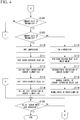
- Figs. 3 , 4 and 5 are flowcharts showing a specific example of the process in which the controller 3 controls the intermittent operation of the indoor blower 13 in the multi-type air conditioner 100 of the embodiment.
- the first controller 31 causes the first indoor unit 1A, the second indoor unit 1B, the third indoor unit 1C, and the outdoor unit 2 to start the heating operation (step S101), and after that, the blowing operation is set for any of the indoor units 1.
- the blowing operation is set for the third indoor unit 1C (step S 102). Even if the cooling operation is set in step S102, the indoor fan performs the blowing operation.
- the second controller 33 determines whether the blowing operation at the time of the heating operation is permitted for the third indoor unit 1C (step S103).
- the second controller 33 opens the indoor expansion valve 12C of the third indoor unit 1C by a minute amount (step S104: micro-opening), and stops the indoor blower 13C (step S105: OFF).
- step S104 micro-opening
- step S105 OFF
- step S106 closing
- step S107 ON
- step S106 The reason why the indoor expansion valve 12C is closed in step S106 is to suppress the warm air from being blown off from the third indoor unit 1C by the operation of the indoor blower 13C. However, it is not always necessary to close the indoor expansion valve 12C when allowing the warm air to be blown off at the time of the blowing operation.
- whether the blowing operation at the time of the heating operation is permitted for the third indoor unit 1C may be determined by any method.
- the second controller 33 may store information indicating permission or disapproval of the blowing operation for the third indoor unit 1C in advance, and determine whether the blowing operation is permitted by referring to the information.
- thermo-off detector 32 determines whether the first indoor unit 1A is in the thermo-off state (step S108). Specifically, the thermo-off detector 32 determines the presence or absence of thermo-off on the basis of the suction pressure and the discharge pressure of the compressor 23. When it is determined that the first indoor unit 1A is in the thermo-off state (step S108-YES), the thermo-off detector 32 determines whether the second indoor unit 1B is in the thermo-off state (step S109).
- step S109-YES when it is determined that the second indoor unit 1B is in the thermo-off state (step S109-YES), the second controller 33 stops the compressor 23 (step S110: OFF), closes the indoor expansion valve 12A (step S111), and then causes the indoor blower 13A to execute an intermittent blowing operation (step S112: intermittent operation). Subsequently, the second controller 33 closes the indoor expansion valve 12B (step S113), and then causes the indoor blower 13B to intermittently execute the blowing operation (step S114: intermittent operation).
- an operation of operating the indoor blower 13 at 300 rpm for 1 minute and then stopping the indoor blower 13 for 1 minute is repeated.
- step S109-NO when it is determined in step S109 that the second indoor unit 1B is not in the thermo-off state (step S109-NO), the second controller 33 operates the compressor 23 (step S115: ON), opens the indoor expansion valve 12B by a minute amount (step S 116: minute opening), and then causes the indoor blower 13A to execute an intermittent blowing operation (step S117: intermittent operation). Subsequently, the first controller 31 controls the indoor expansion valve 12B and the indoor blower 13B by the normal control function (steps S118 and S119).
- the intermittent operation of the indoor blower 13A is performed.
- the second indoor unit 1B is controlled in the same manner as in the normal state.
- step S 108 when it is determined that the first indoor unit 1A is not in the thermo-off state (step S 108-NO), the second controller 33 operates the compressor 23 (step S120), and then the first controller 31 controls the indoor expansion valve 12A and the indoor blower 13A by a normal control function (steps S121 and S122).
- thermo-off detector 32 determines whether the second indoor unit 1B is in the thermo-off state (step S123).
- the second controller 33 opens the indoor expansion valve 12B by a minute amount (step S 124: minute opening), and causes the indoor blower 13B to execute an intermittent blowing operation (step S125: intermittent operation).
- the compressor 23 is not stopped and the first indoor unit 1A is controlled in the same manner as in the normal state. Further, in this case, the intermittent operation of the indoor blower 13B is performed in the state in which the indoor expansion valve 12B is opened by a minute amount (for example, 30 pulses). By such a process, it is possible to prevent the warm air from being blown off from the second indoor unit 1B in the non-heated state.
- step S 123 when it is determined that the second indoor unit 1B is not in the thermo-off state (step S123-NO), the first controller 31 controls the indoor expansion valve 12B and the indoor blower 13B by the normal control function (steps S126, and S127).
- the second controller 33 determines whether all the indoor units 1 are in the non-heating state (step S 128), and when it is determined that any of the indoor units 1 is not in the non-heating state (step S128-NO), the process returns to step S103, and when it is determined that all the indoor units 1 are in the non-heated state, the process is terminated.
- the multi-type air conditioner 100 of the embodiment configured in this way the can suppress the warm wind from being blown off from the indoor unit 1 which is in the non-heated state at the time of the heating operation, by intermittently operating the indoor blower 13 depending on the thermo-off state of the indoor unit 1.
- a multi-type air conditioner can collectively perform air-conditioning of a plurality of spaces, by installing a plurality of indoor units in a plurality of spaces in a dispersed manner.
- all connected indoor units are not always in operation.
- some indoor units may stop the operation by manipulation of the user, or may be temporarily stopped by the thermo-off.
- a minute amount of refrigerant may be circulated in the indoor unit to suppress an occurrence of problems due to liquid accumulation.
- the air conditioner is generally equipped with a room temperature sensor. Therefore, in general, the air conditioner can control the space to be air-conditioned to a comfortable temperature, by controlling each component to be provided on the basis of the room temperature.
- the indoor air may be taken into the indoor unit to detect the room temperature. Therefore, even in the indoor unit of the thermo-off state, the indoor blower is often driven when measuring the room temperature.
- the indoor blower may be driven at the same time in a plurality of indoor units which is in the thermo-off state. Further, in this case, a minute amount of refrigerant may be circulated in the plurality of indoor units which is in the thermo-off state, due to the above-mentioned reason or the like, and in such a case, when the indoor blower is driven, the refrigerant is condensed.
- the cooling operation or the blowing operation may be set in another indoor unit.
- the flow of the refrigerant differs between the cooling operation and the heating operation, even if such a setting is made, the cooling operation and the heating operation cannot be performed at the same time.
- the cooling operation or the blowing operation may be set in the indoor unit that is not performing the heating operation, and in such a case, a minute amount of refrigerant may be circulated to the indoor units. Further, in such a case, when the indoor blower is driven in the indoor units, there is a likelihood that the condensation amount of refrigerant in the indoor unit may increase, and the refrigerant shortage may be likely to occur.
- thermo-off detector which detects the thermo-off of one or a plurality of indoor units at the time of the heating operation
- controller which controls the operation of the compressor and the operation of the indoor expansion valve or the indoor blower of the one or plurality of indoor units, on the basis of a result of the detection of the thermo-off, when there is an indoor unit which does not performing the heating operation, among the one or plurality of indoor units, it is possible to suppress the warm air from being blow off from the indoor unit that does not perform the heating operation, in the multi-type air conditioner at the time of the heating operation.
- the number of indoor units 1 included in the multi-type air conditioner 100 may be one or more, and does not necessarily need to be three.
- the number of outdoor units 2 included in the multi-type air conditioner 100 may be two or more, and does not necessarily need to be one.
Landscapes
- Engineering & Computer Science (AREA)
- Mechanical Engineering (AREA)
- General Engineering & Computer Science (AREA)
- Physics & Mathematics (AREA)
- Chemical & Material Sciences (AREA)
- Combustion & Propulsion (AREA)
- Thermal Sciences (AREA)
- Fluid Mechanics (AREA)
- Air Conditioning Control Device (AREA)
Abstract
Description
- An embodiment of the present invention relates to an air conditioner and a control method.
- As one type of an air conditioner, there is a multi-type air conditioner in which a plurality of indoor units are connected to a single outdoor unit. The multi-type air conditioner can collectively perform air-conditioning in a plurality of spaces, by a plurality of indoor units being installed in the plurality of spaces in a dispersed manner. In such a multi-type air conditioner, in some cases, some of the indoor units may enter a state of not performing a heating operation (hereinafter referred to as a "non-heating state") when an overall heating operation is being performed, and a minute amount of refrigerant circulates in the indoor unit in a non-heating state. In the related art, when an indoor blower is driven in such a case, there is a likelihood that the refrigerant will be condensed by heat exchange due to discharging of warm air, and the required amount of gas refrigerant may be insufficient.
-
Japanese Patent No. 3778117 - An object of the present invention is to provide an air conditioner and a control method capable of curbing warm air being blown off from an indoor unit that is not performing a heating operation in a multi-type air conditioner that is performing a heating operation.
- An air conditioner of the embodiment includes one or a plurality of indoor units, one or a plurality of outdoor units, a thermo-off detector, and a controller. The one or plurality of indoor units include an indoor expansion valve and an indoor blower. The one or plurality of outdoor units include a compressor. The thermo-off detector detects the thermo-off of the one or plurality of indoor units at the time of a heating operation. The controller controls an operation of the compressor and an operation of an indoor expansion valve or an indoor blower of the one or plurality of indoor units, on the basis of a result of the detection of the thermo-off, when there is an indoor unit which is not performing a heating operation, among the one or plurality of indoor units.
-
-
Fig. 1 is a diagram showing a configuration example of the multi-type air conditioner (100) of the embodiment. -
Fig. 2 is a diagram showing a specific example of a functional configuration of a controller (3) in the embodiment. -
Fig. 3 is a flowchart showing a specific example of a process in which the controller (3) controls an intermittent operation of an indoor blower (13) in the multi-type air conditioner (100) of the embodiment. -
Fig. 4 is a flowchart showing a specific example of a process in which the controller (3) controls the intermittent operation of the indoor blower (13) in the multi-type air conditioner (100) of the embodiment. -
Fig. 5 is a flowchart showing a specific example of a process in which the controller (3) controls the intermittent operation of the indoor blower (13) in the multi-type air conditioner (100) of the embodiment. - Hereinafter, an air conditioner and a control method of the embodiment will be described with reference to the drawings.
-
Fig. 1 is a diagram showing a configuration example of amulti-type air conditioner 100 of the embodiment. As shown inFig. 1 , themulti-type air conditioner 100 of the embodiment includes, for example, a firstindoor unit 1A, a secondindoor unit 1B, a thirdindoor unit 1C, and an outdoor unit 2, which are four indoor units, and acontroller 3. The firstindoor unit 1A, the secondindoor unit 1B, and the thirdindoor unit 1C are connected to the outdoor unit 2 via a crossover pipe. - In the present embodiment, a configuration of the first
indoor unit 1A, a configuration of the secondindoor unit 1B, and a configuration of the thirdindoor unit 1C are the same. Therefore, the configurations of these three indoor units 1 will be described by taking the firstindoor unit 1A as an example, and a description of the secondindoor unit 1B and the thirdindoor unit 1C will not be provided. - Further, hereinafter, each constituent of the first
indoor unit 1A is identified by adding a letter "A" to a common reference numeral. Similarly, each configuration of the secondindoor unit 1B is identified by adding a letter "B" to a common reference numeral, and each configuration of the thirdindoor unit 1C is identified by adding a letter "C". Further, hereinafter, when the firstindoor unit 1A, the secondindoor unit 1B, and the thirdindoor unit 1C are not particularly distinguished, the letters "A", "B" and "C" are not added, and each common configuration is represented by common reference numerals. - The first
indoor unit 1A is equipped with anindoor heat exchanger 11A, anindoor expansion valve 12A, anindoor blower 13A, and a roomtemperature measuring device 14A. Theindoor heat exchanger 11A is a device that realizes a heat exchange between the refrigerant and the indoor air. Theindoor heat exchanger 11A is connected to theindoor expansion valve 12A by an indoor pipe. For example, theindoor heat exchanger 11A is a fin tube type heat exchanger. - The
indoor expansion valve 12A is a device that expands the refrigerant. For example, theindoor expansion valve 12A is an electronic expansion valve (PMV: Pulse Motor Valve) in which an opening degree can be changed. For example, as the opening degree of theindoor expansion valve 12A is increased, the refrigerant flows more easily in theindoor expansion valve 12A, and as the opening degree of theindoor expansion valve 12A is decreased, the refrigerant flows less easily in theindoor expansion valve 12A. - The
indoor blower 13A is a blower for promoting heat exchange by theindoor heat exchanger 11A. For example, theindoor blower 13A has a centrifugal fan. The fan of theindoor blower 13A is disposed to face theindoor heat exchanger 11A. - The room
temperature measuring device 14A is a device for measuring the room temperature in the vicinity of theindoor heat exchanger 11A. The roomtemperature measuring device 14A is communicatively connected to thecontroller 3, and transmits measurement data to thecontroller 3. - The outdoor unit 2 is equipped with an
outdoor heat exchanger 21, a four-way valve 22, acompressor 23, anoutdoor expansion valve 24, anoutdoor blower 25, adischarge pressure sensor 26, and asuction pressure sensor 27. Theoutdoor heat exchanger 21 is a device that realizes heat exchange between the refrigerant and the outdoor air. Theoutdoor heat exchanger 21 is connected to the four-way valve 22 and theoutdoor expansion valve 24 by an outdoor pipe. For example, theoutdoor heat exchanger 21 is a fin tube type heat exchanger. - The four-way valve 22 is a device that switches a circulation path of the refrigerant inside the
multi-type air conditioner 100. Specifically, the four-way valve 22 switches the circulation path of refrigerant to either a heating operation path or a cooling operation or defrosting operation path. For example,Fig. 1 shows a situation in which the circulation path of the refrigerant is switched to the heating operation path by the four-way valve 22. The four-way valve 22 is connected to the indoor heat exchanger 11, thecompressor 23, and theoutdoor heat exchanger 21 by the outdoor pipe. - The
compressor 23 is a device that compresses the refrigerant supplied from the firstindoor unit 1A, the secondindoor unit 1B or the thirdindoor unit 1C. Thecompressor 23 compresses the refrigerant sucked from the suction port SP, and discharges the compressed refrigerant from the discharge port DP. The refrigerant compressed by thecompressor 23 is sent to the indoor heat exchanger 11 or theoutdoor heat exchanger 21 by the four-way valve 22. Anaccumulator 231 for storing the liquid refrigerant is attached to the suction port SP of thecompressor 23. - The
outdoor expansion valve 24 is a device that expands the refrigerant. For example, theoutdoor expansion valve 24 may be an electronic expansion valve (PMV) similar to theindoor expansion valve 12A. Theoutdoor expansion valve 24 is connected to theoutdoor heat exchanger 21 and the indoor expansion valve 12 by the outdoor pipe. - The
outdoor blower 25 is a blower for promoting the heat exchange by theoutdoor heat exchanger 21. For example, theoutdoor blower 25 has a centrifugal fan similar to the indoor blower 13, and is disposed to face theoutdoor heat exchanger 21. - The
discharge pressure sensor 26 is a device that measures the pressure of the refrigerant discharged from the compressor 23 (hereinafter referred to as a "discharge pressure"). Specifically, thedischarge pressure sensor 26 measures the discharge pressure of the refrigerant at the discharge port DP of thecompressor 23. Thedischarge pressure sensor 26 is communicably connected to thecontroller 3 and transmits the measurement data to thecontroller 3. - The
suction pressure sensor 27 is a device that measures the pressure of the refrigerant sucked into the compressor 23 (hereinafter referred to as a "suction pressure"). Specifically, thesuction pressure sensor 27 detects the suction pressure of the refrigerant at the suction port SP of thecompressor 23. Thesuction pressure sensor 27 is communicably connected to thecontroller 3 and transmits the measurement data to thecontroller 3. - The
controller 3 has a function of controlling the operations of the firstindoor unit 1A, the secondindoor unit 1B, the thirdindoor unit 1C, and the outdoor unit 2. For example, thecontroller 3 is equipped with a central processing unit (CPU), a memory, an auxiliary storage device, and the like connected by a bus, and executes a program. Thecontroller 3 functions as a functional unit equipped with afirst controller 31, a thermo-off detector 32, and asecond controller 33, which will be described later, by executing a program, and controls the operations of the firstindoor unit 1A, the secondindoor unit 1B, the thirdindoor unit 1C, and the outdoor unit 2 by communication performed via a bus. - All or a part of each function of the
controller 3 may be realized, using hardware such as an application specific integrated circuit (ASIC), a programmable logic device (PLD), or a field programmable gate array (FPGA). The program may be recorded on a computer-readable recording medium. The computer-readable recording medium is, for example, a portable medium such as a flexible disk, a magneto-optical disk, a ROM or a CD-ROM, or a storage device such as a hard disk built into a computer system. The program may be transmitted via a telecommunication line. -
Fig. 2 is a diagram showing a specific example of the functional configuration of thecontroller 3 in the embodiment. Thecontroller 3 is equipped with afirst controller 31, a thermo-off detector 32, and asecond controller 33. Thefirst controller 31 has a function of controlling an air-conditioning operation during normal operation by the firstindoor unit 1A, the secondindoor unit 1B, the thirdindoor unit 1C, and the outdoor unit 2 (hereinafter referred to as a "normal control function"). The normal air-conditioning operation referred to herein means the operations of heating, cooling, blowing, defrosting, and the like, which are provided in a conventional air conditioner, and the normal control function includes a function of stopping the indoor unit 1 in which a room temperature has reached a set temperature at the time of the heating operation. In general, stoppage of the indoor unit 1 in which the room temperature has reached the set temperature at the time of the heating operation is referred to as a "thermo-off". - The thermo-
off detector 32 has a function of detecting the thermo-off of the firstindoor unit 1A, the secondindoor unit 1B, and the thirdindoor unit 1C on the basis of the discharge pressure of thecompressor 23 measured by thedischarge pressure sensor 26 and the suction pressure of thecompressor 23 measured by thesuction pressure sensor 27. The thermo-off detector 32 notifies thefirst controller 31 and thesecond controller 33 of the detection result. Further, the thermo-off may be detected when the room temperature measured by the room temperature measuring device 14 reaches the set temperature. - The
second controller 33 has a function of controlling the blowing operation of the indoor unit 1 in themulti-type air conditioner 100 that performs the heating operation as a whole. Specifically, thesecond controller 33 controls the operations of the indoor expansion valve 12, the indoor blower 13, and thecompressor 23 of each indoor unit 1 on the basis of a result of the detection of thermo-off of each indoor unit 1. -
Figs. 3 ,4 and5 are flowcharts showing a specific example of the process in which thecontroller 3 controls the intermittent operation of the indoor blower 13 in themulti-type air conditioner 100 of the embodiment. First, a case is assumed in which thefirst controller 31 causes the firstindoor unit 1A, the secondindoor unit 1B, the thirdindoor unit 1C, and the outdoor unit 2 to start the heating operation (step S101), and after that, the blowing operation is set for any of the indoor units 1. Here, it is assumed that the blowing operation is set for the thirdindoor unit 1C (step S 102). Even if the cooling operation is set in step S102, the indoor fan performs the blowing operation. - In this case, the
second controller 33 determines whether the blowing operation at the time of the heating operation is permitted for the thirdindoor unit 1C (step S103). Here, when the blowing operation at the time of the heating operation is not permitted for the thirdindoor unit 1C (step S103-NO), thesecond controller 33 opens theindoor expansion valve 12C of the thirdindoor unit 1C by a minute amount (step S104: micro-opening), and stops theindoor blower 13C (step S105: OFF). On the other hand, when the blowing operation at the time of the heating operation is permitted for the thirdindoor unit 1C (step S103-YES), thesecond controller 33 closes theindoor expansion valve 12C of the thirdindoor unit 1C (step S106: closing), and operates theindoor blower 13C (step S107: ON). - The reason why the
indoor expansion valve 12C is closed in step S106 is to suppress the warm air from being blown off from the thirdindoor unit 1C by the operation of theindoor blower 13C. However, it is not always necessary to close theindoor expansion valve 12C when allowing the warm air to be blown off at the time of the blowing operation. - Further, whether the blowing operation at the time of the heating operation is permitted for the third
indoor unit 1C may be determined by any method. For example, thesecond controller 33 may store information indicating permission or disapproval of the blowing operation for the thirdindoor unit 1C in advance, and determine whether the blowing operation is permitted by referring to the information. - Subsequently, the thermo-
off detector 32 determines whether the firstindoor unit 1A is in the thermo-off state (step S108). Specifically, the thermo-off detector 32 determines the presence or absence of thermo-off on the basis of the suction pressure and the discharge pressure of thecompressor 23. When it is determined that the firstindoor unit 1A is in the thermo-off state (step S108-YES), the thermo-off detector 32 determines whether the secondindoor unit 1B is in the thermo-off state (step S109). - Here, when it is determined that the second
indoor unit 1B is in the thermo-off state (step S109-YES), thesecond controller 33 stops the compressor 23 (step S110: OFF), closes theindoor expansion valve 12A (step S111), and then causes theindoor blower 13A to execute an intermittent blowing operation (step S112: intermittent operation). Subsequently, thesecond controller 33 closes theindoor expansion valve 12B (step S113), and then causes theindoor blower 13B to intermittently execute the blowing operation (step S114: intermittent operation). - For example, in the intermittent operation, an operation of operating the indoor blower 13 at 300 rpm for 1 minute and then stopping the indoor blower 13 for 1 minute is repeated.
- When the first
indoor unit 1A and the secondindoor unit 1B are in the thermo-off state by the processing so far, thecompressor 23 is stopped, theindoor expansion valves indoor blowers indoor unit 1A and the secondindoor unit 1B in the non-heating state. - On the other hand, when it is determined in step S109 that the second
indoor unit 1B is not in the thermo-off state (step S109-NO), thesecond controller 33 operates the compressor 23 (step S115: ON), opens theindoor expansion valve 12B by a minute amount (step S 116: minute opening), and then causes theindoor blower 13A to execute an intermittent blowing operation (step S117: intermittent operation). Subsequently, thefirst controller 31 controls theindoor expansion valve 12B and theindoor blower 13B by the normal control function (steps S118 and S119). - By the processing so far, when the first
indoor unit 1A is in the thermo-off state and the secondindoor unit 1B is not in the thermo-off state, in a state in which thecompressor 23 is not stopped and theindoor expansion valve 12A is opened by a minute amount (for example, 30 pulse), the intermittent operation of theindoor blower 13A is performed. Further, in this case, the secondindoor unit 1B is controlled in the same manner as in the normal state. By such a process, it is possible to suppress the warm air from being blown off from the firstindoor unit 1A in the non-heated state. - On the other hand, in step S 108, when it is determined that the first
indoor unit 1A is not in the thermo-off state (step S 108-NO), thesecond controller 33 operates the compressor 23 (step S120), and then thefirst controller 31 controls theindoor expansion valve 12A and theindoor blower 13A by a normal control function (steps S121 and S122). - Subsequently, the thermo-
off detector 32 determines whether the secondindoor unit 1B is in the thermo-off state (step S123). Here, when it is determined that the secondindoor unit 1B is in the thermo-off state (step S123-YES), thesecond controller 33 opens theindoor expansion valve 12B by a minute amount (step S 124: minute opening), and causes theindoor blower 13B to execute an intermittent blowing operation (step S125: intermittent operation). - By the processing so far, when the first
indoor unit 1A is not in the thermo-off state and the secondindoor unit 1B is in the thermo-off state, thecompressor 23 is not stopped and the firstindoor unit 1A is controlled in the same manner as in the normal state. Further, in this case, the intermittent operation of theindoor blower 13B is performed in the state in which theindoor expansion valve 12B is opened by a minute amount (for example, 30 pulses). By such a process, it is possible to prevent the warm air from being blown off from the secondindoor unit 1B in the non-heated state. - On the other hand, in step S 123, when it is determined that the second
indoor unit 1B is not in the thermo-off state (step S123-NO), thefirst controller 31 controls theindoor expansion valve 12B and theindoor blower 13B by the normal control function (steps S126, and S127). - When the first
indoor unit 1A and the secondindoor unit 1B are not in the thermo-off state by the processing so far, thecompressor 23 is not stopped, and the firstindoor unit 1A and the secondindoor unit 1B are controlled in the same manner as in the normal state. - Further, the
second controller 33 determines whether all the indoor units 1 are in the non-heating state (step S 128), and when it is determined that any of the indoor units 1 is not in the non-heating state (step S128-NO), the process returns to step S103, and when it is determined that all the indoor units 1 are in the non-heated state, the process is terminated. - The
multi-type air conditioner 100 of the embodiment configured in this way the can suppress the warm wind from being blown off from the indoor unit 1 which is in the non-heated state at the time of the heating operation, by intermittently operating the indoor blower 13 depending on the thermo-off state of the indoor unit 1. - In general, a multi-type air conditioner can collectively perform air-conditioning of a plurality of spaces, by installing a plurality of indoor units in a plurality of spaces in a dispersed manner. In such a multi-type air conditioner, all connected indoor units are not always in operation. For example, in some cases, some indoor units may stop the operation by manipulation of the user, or may be temporarily stopped by the thermo-off. In this case, it is not necessary to circulate the refrigerant in the indoor unit which is originally in the non-heated state or the thermo-off state. However, in the non-heating state or the thermo-off state at the time of the heating operation, in some cases, a minute amount of refrigerant may be circulated in the indoor unit to suppress an occurrence of problems due to liquid accumulation.
- On the other hand, the air conditioner is generally equipped with a room temperature sensor. Therefore, in general, the air conditioner can control the space to be air-conditioned to a comfortable temperature, by controlling each component to be provided on the basis of the room temperature. When trying to measure the room temperature for the purpose of such a control, in order to prevent the room temperature sensor of the indoor unit of the thermo-off state from being affected by the temperature of the indoor heat exchanger, the indoor air may be taken into the indoor unit to detect the room temperature. Therefore, even in the indoor unit of the thermo-off state, the indoor blower is often driven when measuring the room temperature.
- Further, in such a multi-type air conditioner, the indoor blower may be driven at the same time in a plurality of indoor units which is in the thermo-off state. Further, in this case, a minute amount of refrigerant may be circulated in the plurality of indoor units which is in the thermo-off state, due to the above-mentioned reason or the like, and in such a case, when the indoor blower is driven, the refrigerant is condensed. When this occurs in the plurality of indoor units at the same time, when a rotation speed of the indoor blower is high and an air volume is large, or when a large amount of refrigerant is flowing, the condensation amount of refrigerant increases, and a sudden drop of the pressure, refrigerant shortage or the like is likely to occur.
- Further, in such a multi-type air conditioner, when any indoor unit is performing the heating operation, the cooling operation or the blowing operation may be set in another indoor unit. In such a case, since the flow of the refrigerant differs between the cooling operation and the heating operation, even if such a setting is made, the cooling operation and the heating operation cannot be performed at the same time.
- In this way, in the multi-type air conditioner, when the heating operation is performed as a whole, the cooling operation or the blowing operation may be set in the indoor unit that is not performing the heating operation, and in such a case, a minute amount of refrigerant may be circulated to the indoor units. Further, in such a case, when the indoor blower is driven in the indoor units, there is a likelihood that the condensation amount of refrigerant in the indoor unit may increase, and the refrigerant shortage may be likely to occur.
- According to at least one embodiment described above, by including the thermo-off detector which detects the thermo-off of one or a plurality of indoor units at the time of the heating operation, and the controller which controls the operation of the compressor and the operation of the indoor expansion valve or the indoor blower of the one or plurality of indoor units, on the basis of a result of the detection of the thermo-off, when there is an indoor unit which does not performing the heating operation, among the one or plurality of indoor units, it is possible to suppress the warm air from being blow off from the indoor unit that does not perform the heating operation, in the multi-type air conditioner at the time of the heating operation.
- The number of indoor units 1 included in the
multi-type air conditioner 100 may be one or more, and does not necessarily need to be three. The number of outdoor units 2 included in themulti-type air conditioner 100 may be two or more, and does not necessarily need to be one. - Although some embodiments of the present invention have been described, these embodiments are presented as examples and are not intended to limit the scope of the invention. These embodiments can be implemented in various other forms, and various omissions, replacements, and changes can be made without departing from the gist of the invention. These embodiments and modifications thereof are included in the scope and gist of the invention as well as in the scope of the invention described in the claims and the equivalent scope thereof.
Claims (11)
- An air conditioner comprising:one or a plurality of indoor units including an indoor expansion valve and an indoor blower;one or a plurality of outdoor units including a compressor;a thermo-off detector which detects thermo-off of the one or plurality of indoor units at the time of a heating operation; anda controller which controls an operation of the compressor and an operation of the indoor expansion valve or the indoor blower of the one or plurality of indoor units, on the basis of a result of the detection of the thermo-off, when there is an indoor unit which is not performing the heating operation, among the one or plurality of indoor units.
- The air conditioner according to claim 1, wherein the controller causes the indoor blower of the indoor unit, which is in a thermo-off state, to perform an intermittent blow operation.
- The air conditioner according to claim 2, wherein the controller closes the indoor expansion valve of the indoor unit, which is in the thermo-off state, before executing the intermittent blowing operation.
- The air conditioner according to any one of claims 1 to 3, wherein when indoor units in a thermo-off state and indoor units in a non-thermo-off state are mixed in the indoor units other than an indoor unit which is not performing a heating operation, the indoor expansion valve of the indoor unit which is in the thermo-off state is opened by a minute amount.
- The air conditioner according to any one of claims 1 to 4, wherein the controller stops the operation of the compressor, when all the indoor units other than the indoor unit which is not performing the heating operation are in the thermo-off state.
- The air conditioner according to any one of claims 1 to 5, wherein when the blowing operation has been made not to be permitted in advance for the indoor unit which is not performing the heating operation, the controller causes the indoor blower of the indoor unit to execute the blowing operation.
- The air conditioner according to claim 6, wherein the controller closes the indoor expansion valve of the indoor unit, before causing the indoor unit which is not performing the heating operation to execute the blowing operation.
- The air conditioner according to any one of claims 1 to 7, wherein when the blowing operation is not permitted in advance for the indoor unit which is not performing the heating operation, the controller stops the indoor blower of the indoor unit.
- The air conditioner according to claim 8, wherein the controller opens the indoor expansion valve of the indoor unit by a minute amount, before stopping the indoor blower of the indoor unit which is not performing the heating operation.
- The air conditioner according to any one of claims 1 to 9, wherein the indoor unit which is not in the heating operation is an indoor unit in which the cooling operation or the blowing operation is set at the time of the heating operation of the air conditioner.
- A control method of an air conditioner equipped with one or a plurality of indoor units including an indoor expansion valve and an indoor blower, and one or a plurality of outdoor units including a compressor, the control method comprising:detecting thermo-off of the one or plurality of indoor units at the time of a heating operation; andcontrolling an operation of the compressor and an operation of the indoor expansion valve or the indoor blower of the one or plurality of indoor units, on the basis of a result of the detection of the thermo-off, when there is an indoor unit which does not performing the heating operation, among the one or plurality of indoor units.
Applications Claiming Priority (1)
| Application Number | Priority Date | Filing Date | Title |
|---|---|---|---|
| PCT/JP2018/034819 WO2020059077A1 (en) | 2018-09-20 | 2018-09-20 | Air conditioner and control method |
Publications (2)
| Publication Number | Publication Date |
|---|---|
| EP3855089A1 true EP3855089A1 (en) | 2021-07-28 |
| EP3855089A4 EP3855089A4 (en) | 2022-04-13 |
Family
ID=69888569
Family Applications (1)
| Application Number | Title | Priority Date | Filing Date |
|---|---|---|---|
| EP18934249.6A Withdrawn EP3855089A4 (en) | 2018-09-20 | 2018-09-20 | AIR CONDITIONING AND CONTROL PROCEDURES |
Country Status (5)
| Country | Link |
|---|---|
| EP (1) | EP3855089A4 (en) |
| JP (1) | JPWO2020059077A1 (en) |
| KR (1) | KR20210042981A (en) |
| CN (1) | CN112714847A (en) |
| WO (1) | WO2020059077A1 (en) |
Family Cites Families (17)
| Publication number | Priority date | Publication date | Assignee | Title |
|---|---|---|---|---|
| JP2903997B2 (en) * | 1993-09-30 | 1999-06-14 | 三菱電機株式会社 | Drain pump control unit for air conditioner |
| JPH11173628A (en) * | 1997-12-15 | 1999-07-02 | Mitsubishi Heavy Ind Ltd | Air conditioner |
| JP3778117B2 (en) | 2002-03-28 | 2006-05-24 | ダイキン工業株式会社 | Air conditioner |
| JP3742859B2 (en) * | 2002-03-28 | 2006-02-08 | ダイキン工業株式会社 | Indoor unit of air conditioner and air conditioner |
| WO2010106807A1 (en) * | 2009-03-19 | 2010-09-23 | ダイキン工業株式会社 | Air conditioning device |
| JP2011149615A (en) * | 2010-01-21 | 2011-08-04 | Mitsubishi Electric Corp | Air conditioning system |
| CN201652706U (en) * | 2010-04-23 | 2010-11-24 | 青岛海信日立空调系统有限公司 | A new air conditioner controller |
| JP5598353B2 (en) * | 2011-01-28 | 2014-10-01 | ダイキン工業株式会社 | Air conditioner |
| JP5916489B2 (en) * | 2012-04-06 | 2016-05-11 | 三菱重工業株式会社 | Control apparatus and method, program, and multi-type air conditioning system including the same |
| WO2013161584A1 (en) * | 2012-04-23 | 2013-10-31 | 三菱電機株式会社 | Air conditioning system |
| JP6053201B2 (en) * | 2013-02-06 | 2016-12-27 | ダイキン工業株式会社 | Refrigeration equipment |
| JP5998984B2 (en) * | 2013-02-26 | 2016-09-28 | 株式会社富士通ゼネラル | Air conditioner |
| CN103791588B (en) * | 2014-01-21 | 2016-08-24 | 宁波奥克斯电气股份有限公司 | Solve the control method that VRF Air Conditioning System cold-producing medium is on the low side |
| JP5872110B1 (en) * | 2014-06-30 | 2016-03-01 | 日立アプライアンス株式会社 | Air conditioner |
| CN104896621B (en) * | 2015-06-09 | 2017-08-29 | 广东美的暖通设备有限公司 | The control method of multi-online air-conditioning system and multi-online air-conditioning system |
| CN107560092B (en) * | 2017-09-25 | 2019-10-22 | 珠海格力电器股份有限公司 | Multi-split air conditioner running state control method and system and heat pump multi-split air conditioner |
| CN108006909B (en) * | 2017-11-21 | 2020-05-08 | 广东美的暖通设备有限公司 | Multi-split air conditioning system and control method of electronic expansion valve in heating mode of multi-split air conditioning system |
-
2018
- 2018-09-20 WO PCT/JP2018/034819 patent/WO2020059077A1/en not_active Ceased
- 2018-09-20 KR KR1020217007761A patent/KR20210042981A/en not_active Ceased
- 2018-09-20 CN CN201880097783.6A patent/CN112714847A/en active Pending
- 2018-09-20 EP EP18934249.6A patent/EP3855089A4/en not_active Withdrawn
- 2018-09-20 JP JP2020547543A patent/JPWO2020059077A1/en active Pending
Also Published As
| Publication number | Publication date |
|---|---|
| JPWO2020059077A1 (en) | 2021-08-30 |
| WO2020059077A1 (en) | 2020-03-26 |
| EP3855089A4 (en) | 2022-04-13 |
| CN112714847A (en) | 2021-04-27 |
| KR20210042981A (en) | 2021-04-20 |
Similar Documents
| Publication | Publication Date | Title |
|---|---|---|
| EP3260791B1 (en) | Air conditioning system | |
| EP1985936B1 (en) | Air Conditioner and Control Method thereof | |
| KR102080852B1 (en) | An air conditioner, an air condition system and a control method thereof | |
| US11493228B2 (en) | Ventilation system and heat exchange-type ventilation device | |
| JP2016090175A (en) | Indoor unit and air conditioner including the same | |
| CN113302434A (en) | Air conditioner and control method thereof | |
| JP6932259B2 (en) | Air conditioner and operating condition judgment method | |
| CN109373540A (en) | A kind of air conditioning control method, system and air conditioner | |
| EP3859244A1 (en) | Air-conditioner | |
| KR20150125343A (en) | Air conditioner and method for control of air conditioner | |
| WO2019097604A1 (en) | Duct type air conditioner | |
| JP2015169399A (en) | Ventilation equipment | |
| JP2002071188A (en) | Heat medium supply abnormality detection device | |
| WO2018198688A1 (en) | Air conditioner | |
| WO2022064764A1 (en) | Floor-type air conditioner | |
| JPWO2020059077A1 (en) | Air conditioner and control method | |
| JPWO2018216130A1 (en) | Air conditioner | |
| JP6501912B2 (en) | Air conditioner | |
| JP7081928B2 (en) | Air volume change detector | |
| KR20090064979A (en) | Duct type air conditioning system and control method | |
| JPH10311592A (en) | Air conditioner | |
| KR20200089045A (en) | Control apparatus for driving air conditioner | |
| JP7478523B2 (en) | Air conditioning device and control method | |
| KR100732417B1 (en) | Air conditioner and its control method | |
| JP2014219131A (en) | Air conditioner |
Legal Events
| Date | Code | Title | Description |
|---|---|---|---|
| STAA | Information on the status of an ep patent application or granted ep patent |
Free format text: STATUS: THE INTERNATIONAL PUBLICATION HAS BEEN MADE |
|
| PUAI | Public reference made under article 153(3) epc to a published international application that has entered the european phase |
Free format text: ORIGINAL CODE: 0009012 |
|
| STAA | Information on the status of an ep patent application or granted ep patent |
Free format text: STATUS: REQUEST FOR EXAMINATION WAS MADE |
|
| 17P | Request for examination filed |
Effective date: 20210324 |
|
| AK | Designated contracting states |
Kind code of ref document: A1 Designated state(s): AL AT BE BG CH CY CZ DE DK EE ES FI FR GB GR HR HU IE IS IT LI LT LU LV MC MK MT NL NO PL PT RO RS SE SI SK SM TR |
|
| DAV | Request for validation of the european patent (deleted) | ||
| DAX | Request for extension of the european patent (deleted) | ||
| A4 | Supplementary search report drawn up and despatched |
Effective date: 20220316 |
|
| RIC1 | Information provided on ipc code assigned before grant |
Ipc: F25B 13/00 20060101ALI20220310BHEP Ipc: F24F 11/74 20180101ALI20220310BHEP Ipc: F24F 11/86 20180101AFI20220310BHEP |
|
| STAA | Information on the status of an ep patent application or granted ep patent |
Free format text: STATUS: THE APPLICATION IS DEEMED TO BE WITHDRAWN |
|
| 18D | Application deemed to be withdrawn |
Effective date: 20221018 |