EP3855030A1 - A fixing clip - Google Patents
A fixing clip Download PDFInfo
- Publication number
- EP3855030A1 EP3855030A1 EP20214752.6A EP20214752A EP3855030A1 EP 3855030 A1 EP3855030 A1 EP 3855030A1 EP 20214752 A EP20214752 A EP 20214752A EP 3855030 A1 EP3855030 A1 EP 3855030A1
- Authority
- EP
- European Patent Office
- Prior art keywords
- fixing clip
- resiliently deformable
- ribs
- stud
- rib
- Prior art date
- Legal status (The legal status is an assumption and is not a legal conclusion. Google has not performed a legal analysis and makes no representation as to the accuracy of the status listed.)
- Granted
Links
Images


Classifications
-
- F—MECHANICAL ENGINEERING; LIGHTING; HEATING; WEAPONS; BLASTING
- F16—ENGINEERING ELEMENTS AND UNITS; GENERAL MEASURES FOR PRODUCING AND MAINTAINING EFFECTIVE FUNCTIONING OF MACHINES OR INSTALLATIONS; THERMAL INSULATION IN GENERAL
- F16B—DEVICES FOR FASTENING OR SECURING CONSTRUCTIONAL ELEMENTS OR MACHINE PARTS TOGETHER, e.g. NAILS, BOLTS, CIRCLIPS, CLAMPS, CLIPS OR WEDGES; JOINTS OR JOINTING
- F16B37/00—Nuts or like thread-engaging members
- F16B37/08—Quickly-detachable or mountable nuts, e.g. consisting of two or more parts; Nuts movable along the bolt after tilting the nut
- F16B37/0807—Nuts engaged from the end of the bolt, e.g. axially slidable nuts
- F16B37/0857—Nuts engaged from the end of the bolt, e.g. axially slidable nuts with the threaded portions of the nut engaging the thread of the bolt by the action of one or more springs or resilient retaining members
-
- B—PERFORMING OPERATIONS; TRANSPORTING
- B60—VEHICLES IN GENERAL
- B60R—VEHICLES, VEHICLE FITTINGS, OR VEHICLE PARTS, NOT OTHERWISE PROVIDED FOR
- B60R16/00—Electric or fluid circuits specially adapted for vehicles and not otherwise provided for; Arrangement of elements of electric or fluid circuits specially adapted for vehicles and not otherwise provided for
- B60R16/02—Electric or fluid circuits specially adapted for vehicles and not otherwise provided for; Arrangement of elements of electric or fluid circuits specially adapted for vehicles and not otherwise provided for electric constitutive elements
- B60R16/0207—Wire harnesses
- B60R16/0215—Protecting, fastening and routing means therefor
-
- H—ELECTRICITY
- H02—GENERATION; CONVERSION OR DISTRIBUTION OF ELECTRIC POWER
- H02G—INSTALLATION OF ELECTRIC CABLES OR LINES, OR OF COMBINED OPTICAL AND ELECTRIC CABLES OR LINES
- H02G3/00—Installations of electric cables or lines or protective tubing therefor in or on buildings, equivalent structures or vehicles
- H02G3/26—Installations of cables, lines, or separate protective tubing therefor directly on or in walls, ceilings, or floors
- H02G3/263—Installation, e.g. suspension, of conduit channels or other supports
Definitions
- the invention relates to a fixing clip.
- the invention relates to a fixing clip for fixing to a ridged component, such as a threaded stud or welding pin.
- the invention also relates to an assembly comprising a fixing clip.
- Figures 1 to 14 relate to an assembly 1 having a first exemplary fixing clip 10 and a second fixing clip 40 and these figures will be referred to interchangeably throughout this description.
- the illustrated assembly 1 includes a cable channel 3 and two fixing clips 10, 40 integral with a side wall 4 of the cable channel 3 and secured to respective threaded studs 5A, 5B. Studs 5A, 5B may be welded, or otherwise secured, to a base plate or similar surface (not shown) against which the assembly 1 is mounted.
- the fixing clip 10 includes a pair of resiliently deformable ribs 14 having a corresponding edge 16 for gripping a thread 7 of the stud 5.
- the edge 16 may be a uniform edge or may be serrated or have one or more teeth for gripping the stud 5.
- the pair of ribs 14 define a gap therebetween for receiving the stud 5.
- the first and second ribs 14 are shaped to guide the stud 5 into the gap. As illustrated, one way of achieving this is to angle the ribs 14 in the direction of insertion of the stud 5 into the gap, the thread 7 is able to pass over the ribs 14 by deforming the ribs 14 away from one another.
- each of the first and second ribs 14 are arranged to engage the stud 5 and shaped such that movement of the stud 5 in a first direction relative to the fixing clip 10 causes each of the first and second ribs 14 to deform.
- the first and second ribs 14 each comprise an engaging surface arranged such that upon application of an external force to the engaging surface, for example by a tool or a finger and/or thumb of a user, each of the first and second ribs 14 are configured to deform so as to release the stud 5 for movement in the extraction direction.
- the fixing clip 10 also includes a second pair of ribs 26 extending from a body 11 of the fixing clip 10.
- the body 11 includes an opening 13 for receiving the stud 5, and the second pair of ribs 26 from the body 11 into the opening 13.
- the second pair of ribs 26 are shaped to guide the stud 5 towards a predetermined position between the first pair of ribs 14. As shown, the second pair of ribs 26 guide the stud 5 to a central position within the fixing clip 10. However, it would be apparent that this was not essential and that the second pair of ribs 26 may be shaped to guide the stud 5 to a different predetermined position as required.
- this is achieved by angling the respective underside 28 of each of the second pair of ribs 26 in the insertion direction of the stud 5.
- the second pair of ribs 26 are shown illustrated in a perpendicular direction to the first pair of ribs 14.
- the free ends of the second pair of ribs 26 also define a tolerance of the fixing clip 10 within which the stud 5 may be located.
- the present fixing clip 10 releasably secures the assembly 1 to the stud 5, as it is possible to release the grip of the ribs 14 on the stud 5 using a lever 18 secured to each of the respective ribs 14.
- Each lever 18 has an engaging surface 20 for applying a load to a respective rib 14 to move the rib 14 in an opening direction.
- the levers 18 are opposed to one another, and as such the engaging surfaces 20 are also opposed to one another.
- applying the load to the levers 18 will push the levers 18, and therefore the ribs 14, apart from one another which will space the edges 16 from the stud 5 and allow the stud 5 to be moved in the extraction direction.
- the levers 18 are also shown offset to one another in a lateral direction that is perpendicular to the insertion direction of the stud 5. This provides a more ergonomic opening mechanism for a user as they can easily push the levers 18 using a thumb and finger of a hand. As shown in Figure 5 , the edge 16 of the ribs 14 only extend partially across a width of the rib 14 and partially overlap the lever 18. However it would be apparent this was merely exemplary and that other rib configurations which would achieve the described functionality were possible.
- the base plate applies a load to a pair of resiliently deformable wings 24 of the fixing clip 10. This results in a biasing force being applied to the fixing clip 10 in the extraction direction.
- This provides a more robust fixation between the fixing clip 10 and the stud 5, as the biasing force acts to pull the stud 5 out of the fixing clip 10 which causes the ribs 14 to engage further with the stud 5 and reducing any relative movement between the stud 5 and the ribs 14 when the fixing clip 10 is secured to the stud 5.
- Fixing clip 40 is best illustrated in Figures 9 to 14 .
- the fixing clip 40 has similar structures to those described in relation to fixing clip 10, and similar reference numerals have been used to denote identical features.
- the fixing clip 40 includes a body having an opening and two protrusions 42 that protrude into the opening.
- the protrusions 42 protrude in a perpendicular direction to the pair of ribs 14 that grip the stud 5 in the same manner as described above.
- the edge 16 of each rib 14 extends across the width of the rib 14, which thus provides an elongate gap within which the stud 5 can be gripped. This advantageously increases the tolerance of the stud 5 placement within the fixing clip 40.
- the fixing clip 40 can be opened in a similar manner to fixing clip 10 by a user pressing the opposed engaging surfaces 20 (arrows F).
- Figure 13 illustrates the offset "L1" between the opposed levers in the perpendicular direction.
- Figure 14 shows the levers 18 in a first position, where the stud 5 is gripped, and a second position 18', where the levers have been separated from one another which allows for easy extraction of the stud 5.
- the fixing clip 40 also includes a wall 46 for limiting the deformation of the lever 18.
- a wall 46 for limiting the deformation of the lever 18.
- the present fixing clip 18 ensures the lever 18 only undergoes elastic deformation, which increases the longevity of the fixing clip 40.
- a side wall 4 of the cable channel 3 is shown as providing a similar function for the opposed lever 18, it would be apparent this was not essential and a second wall may be provided for limiting the deformation of the lever adjacent the cable channel 3 in the same manner as wall 46.
- the fixing clip 40 allows cable channels 3 to be removed and reused.
- the removal of cable channels, facilitated by the fixing clip can be repeated many times without damaging the cable channel, and without decreasing the performance of fixing points 40 on the stud 5, as the removal of the cable channel 3 is facilitated without compromising retention characteristics.
- fixing clip 10 and fixing clip 40 it is possible to accommodate larger manufacturing tolerances of stud 5 placement, whilst also a retaining high retention force of the stud.
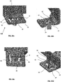
- FIGs 15 to 19 relate to an assembly 1 having a third exemplary fixing clip 60 and these figures will be referred to interchangeably throughout this description.
- the cable channel 3 has two fixing clips 60A, 60B secured thereto.
- the fixing clip 60 has similar structures to those described in relation to fixing clip 10 and fixing clip 40, and similar reference numerals have been used to denote identical features.
- the fixing clip 60 includes a body 11 providing an opening 70 and a pair of ribs 14 extending from the body 11, each rib 14 having an edge 16 and the pair of edges 16 defining a gap 72 therebetween for gripping the stud 5 in the manner described above. As shown in Figure 17 , the gap 72 within which the stud 5 can be gripped is elongate, which accommodates greater tolerances in stud 5 placement on the base plate.
- both fixing clips 40 By having both fixing clips 40 with an elongate gap 72, both fixing clips 40A, 40B are able to accommodate greater tolerances of stud 5 placement. While the edge 16 of both ribs 14 are shown as extending across the entire width of the respective rib 14, it would be apparent this was not essential and that the edge 16 may only extend partially across the width of one or both ribs 14.
- Each rib 14 is also shown having a pair of abutments 62 extending therefrom in a substantially parallel direction to the insertion direction 68 of the stud 5.
- the pairs of abutments 62 are arranged to abut one another when the stud 5 is moved in the extraction direction (arrows A).
- the abutment of the pairs of abutments 62 stiffens the ribs 14, which in turn increases the retention force of the ribs 14, further enhancing the grip of the fixing clip 60. It is also advantageous to use the described abutments 62, as the insertion force is not increased due to the presence of the abutments 62.
- the fixing clip 60 is provides increased stiffness or resistance when extracting the stud 5, without also having a corresponding increase in stiffness or resistance during insertion of the stud 5. While each rib 14 is shown having a pair of abutments 62, it would be apparent that this was not essential and that one or more than two abutments 62 may be used to stiffen the ribs 14 in the manner described. Similarly, while the abutments 62 are shown extending in a direction substantially parallel to the insertion direction 68, it would be apparent this was not essential, and that the abutments 62 may extend in other directions or have other shapes while still stiffening the ribs 14 in the manner described.
- An underside 64 of the body 11 is also offset from an underside 66 of the cable channel 3 in the extraction direction.
- the cable channel 3 can be mounted on an insulating foam (not shown) underneath the underside 66, by positioning the underside 64 of the body 11 further from the underside 66 of the channel 3 in the extraction direction, this generates a biasing or pre-loading force on the fixing clip 60 when the cable channel 3 is secured to the stud 5.
- the ribs 14 have an engaging surface 74 for engaging a tool.
- the tool may be a screwdriver, or any type of tool that can engage the engaging surface 74 to apply a force to the engaging surfaces 74 for separating the ribs 14 from one another.
- the ribs 14 are also raised above the body 11 to provide a gap 76 to provide a more ergonomic fixing clip 60, as the gap 76 is able to accommodate insertion of the tool from a greater range of angles than if the ribs 14 were not raised above the body 11.
- a user can insert a simple tool into the gap 76 under the raised ribs 14 and lever the tool on the body 11 to easily open the ribs with a low force.
- ribs 14 raised above the body 11 is preferable, it would be apparent that this was not essential to the function of the fixing clip 60 or the engaging surfaces 74. While the ribs 14 are shown extending from the body 11 within the opening 70 and protruding above the opening in the insertion direction 68, it would be apparent this was not essential, and that the ribs may extend from other parts of the body 11.
- FIGS 20 to 25 relate to an assembly 1 having a fourth 90A and fifth 90B exemplary fixing clips and these figures will be referred to interchangeably throughout this description.
- the cable channel 3 has two different fixing clips 90A, 90B secured thereto.
- Fixing clips 90A, 90B has similar structures to those described in relation to fixing clips 10, 40 and 60, and similar reference numerals have been used to denote identical features.
- the fixing clips 90A, 90B include a body 91 providing an opening 94 and a pair of ribs 14 extending from the body 91, each rib 14 having an edge 16 and the pair of edges 16 defining a gap 96 therebetween for gripping the stud 5 in the manner described above.
- An underside 92 of the body 91 is offset from an underside 93 of the cable channel 3 in the extraction direction.
- the cable channel 3 can be mounted on an insulating foam (not shown) disposed adjacent the underside 92, positioning the underside 92 of the body 91 further from underside 93 of the channel 3 in the extraction direction generates a biasing (or pre-loading) force on the fixing clips 90A, 90B when the cable channel 3 is secured to the stud 5 in the manner described above.
- Fixing clip 90A is best illustrated in Figures 22a to 22d and shows each rib 14 has a lever 18 for moving the rib 14 in the manner described above, and an edge 16 for gripping the stud 5 in the manner described above.
- the body 91 also includes a pair of opposed protrusions 42 extending into the opening 94 for providing an elongate gap 96 between the edges 16 to accommodate greater tolerances ("L2" in Figure 23b ) of stud placement.
- the ribs 14 are also angled to guide the stud 5 into a central position in the fixing clip 90A in the manner described above.
- the opposed protrusions 42 extend into the opening 94 in a perpendicular direction to the ribs 14.
- Fixing clip 90B is best illustrated in Figures 24a to 24d and shows each rib 14 has a lever 18 for moving the rib 14 in the manner described above, a pair of abutments 62 for stiffening the ribs 14, and an edge 16 for gripping the stud 5 in the manner described above.
- Fixing clip 90B differs from fixing clip 90A by not having the pair of opposed protrusions 42. However, an elongate gap 96 is still provided between the edges 16 of fixing clip 90B by edges 16 extending across the width of the ribs 14. Thus, fixing clip 90B is able to accommodate greater tolerances ("L3" in Figure 25b ) of stud placement due to the elongate gap 96 as the stud 5.
- Each rib 14 also has a curved section which extends toward the opposed rib 14. This curved section is shown extending from a side of the rib 14 and provides the greater tolerance of fixing clip 90B. It would be apparent that tolerances L2 and L3 may be the same or may be different depending on the tolerances of the stud placement.
- the ribs 14 are also angled to guide the stud 5 into a central position in the fixing clip 90A in the manner described above.
- each rib 14 is also shown having an abutment 62 formed integrally therewith and arranged to abut a corresponding abutment 62 on the opposed rib 14. While the illustrated fixing clip 90B shows a lever 18 having an abutment 62 abutting an abutment 62 without a lever formed therewith, it would be apparent that this was not essential. However, by offsetting the levers 18 in a perpendicular direction to the insertion direction 68, the ergonomics of the fixing clip 90B is improved.
- the shaped ribs 14 are able to securely grip the stud, whilst also being optimised to position the cable channel 3 into the desired position on the base plate by accommodating greater tolerances of the position of the studs on the base plate.
- the engaging surfaces enable the cable channel 3 to be removable and reusable. This operation can be repeated several times without damaging the cable channel 3 and without decreasing the performance of the fixing clips, for example the insertion force and retention force are maintained over time.
- the fixing clips described herein may be used to secure other parts to a base plate, or similar structure.
- the fixing clip is described as being integral with the cable channel, it would be apparent that the fixing clip may be provided as a separate independent component that can be connected to the cable channel for securing the cable channel in the manner described herein.
Landscapes
- Engineering & Computer Science (AREA)
- General Engineering & Computer Science (AREA)
- Mechanical Engineering (AREA)
- Clamps And Clips (AREA)
Abstract
Description
- The invention relates to a fixing clip. In particular, the invention relates to a fixing clip for fixing to a ridged component, such as a threaded stud or welding pin. The invention also relates to an assembly comprising a fixing clip.
- Example embodiment(s) of the invention are illustrated in the accompanying drawings, in which:
-
Figure 1 illustrates a side view of an assembly having an exemplary fixing clip and a threaded stud; -
Figure 2 illustrates a perspective view of the assembly ofFigure 1 ; -
Figures 3 & 4 illustrate perspective views of a fixing clip and a threaded stud; -
Figures 5 & 6 illustrate top and bottom views of a fixing clip and a threaded stud; -
Figure 7 illustrates a side perspective view of the fixing clip and the threaded stud ofFigure 5 ; -
Figure 8 illustrates a side section view of the fixing clip and the threaded stud ofFigure 5 ; -
Figures 9 & 10 illustrate top and bottom views of a second exemplary fixing clip and a threaded stud; -
Figure 11 illustrates a side perspective view of the fixing clip and the threaded stud ofFigure 9 ; -
Figures 12 to14 illustrate perspective views of a fixing clip and a threaded stud; -
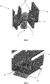
Figure 15 illustrates a top view of an assembly having a third example embodiment of a fixing clip and a threaded, welded stud (a) when closed and (b) when open; -
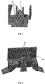
Figure 16 illustrates a close-up perspective view of the fixing point on the stud, (a) where two ribs grip the welded stud to ensure the retention force, and (b) where a support plane of the fixing clip is lower than the channel underside and where the interference with insulating foam (located below the cable channel) ensures a preloading (or biasing force); -
Figure 17 illustrates a top-, bottom- and perspective side-view of a fixing clip when engaged with the stud; -
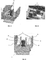
Figure 18 illustrates a perspective sectional side-view the fixing clip engaged with the stud, where the sloped profile and the shape of the ribs guide the stud in the correct position during insertion of the stud into the fixing clip; -
Figure 19 illustrates a perspective side-view of a close-up of the fixing clip engaged with the stud (a) focussing on the two raised ribs, and (b) on the four vertical abutments; -
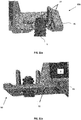
Figure 20 illustrates a top view of an assembly having fourth and fifth exemplary embodiments of a fixing clip and a threaded, welded stud (a) when closed and (b) when open; -
Figure 21 illustrates a close-up perspective view of the fixing point on the stud (both of them can cover the tolerances), (a) where two ribs grip the welded stud ensuring a retention force, and (b) where the support plane of the fixing clip is lower than the underside of the cable channel, and where the interference with the insulating foam, located below the cable channel, ensures a preloading; -
Figures 22a to 22d illustrate perspective views of the fourth embodiment of the fixing clip ofFigure 20 ; -
Figure 23 illustrates (a) perspective sectional close-up view and (b) a top view of the clip in engagement with the stud shown inFigure 22 ; -
Figure 24 illustrates various perspective views of the fifth embodiment of the fixing clip ofFigure 20 , and -
Figure 25 (a) perspective sectional close-up view and (b) a top view of the clip in engagement with the stud shown inFigure 24 . -
Figures 1 to 14 relate to anassembly 1 having a firstexemplary fixing clip 10 and asecond fixing clip 40 and these figures will be referred to interchangeably throughout this description. The illustratedassembly 1 includes acable channel 3 and twofixing clips side wall 4 of thecable channel 3 and secured to respective threadedstuds Studs assembly 1 is mounted. - As shown in
Figure 3 , thefixing clip 10 includes a pair of resilientlydeformable ribs 14 having acorresponding edge 16 for gripping athread 7 of thestud 5. It would be apparent theedge 16 may be a uniform edge or may be serrated or have one or more teeth for gripping thestud 5. The pair ofribs 14 define a gap therebetween for receiving thestud 5. The first andsecond ribs 14 are shaped to guide thestud 5 into the gap. As illustrated, one way of achieving this is to angle theribs 14 in the direction of insertion of thestud 5 into the gap, thethread 7 is able to pass over theribs 14 by deforming theribs 14 away from one another. However, when trying to move thestud 5 in an extraction direction opposite to the insertion direction, theribs 14 engage thethread 7 and prevent thestud 5 from being removed from thefixing clip 10, thus providing a secure fixation between thefixing clip 10 and thestud 5. A further advantage ofribs 14 angled in the insertion direction is to guide thestud 5 towards the gap between theedges 16 when theassembly 1 is pressed onto thestuds 5 formed on a base plate. Thus, each of the first andsecond ribs 14 are arranged to engage thestud 5 and shaped such that movement of thestud 5 in a first direction relative to thefixing clip 10 causes each of the first andsecond ribs 14 to deform. Furthermore, movement of thestud 5 in the extraction direction is prevented by engagement between eachrib 14 and thestud 5. The first andsecond ribs 14 each comprise an engaging surface arranged such that upon application of an external force to the engaging surface, for example by a tool or a finger and/or thumb of a user, each of the first andsecond ribs 14 are configured to deform so as to release thestud 5 for movement in the extraction direction. - The
fixing clip 10 also includes a second pair ofribs 26 extending from abody 11 of thefixing clip 10. Thebody 11 includes anopening 13 for receiving thestud 5, and the second pair ofribs 26 from thebody 11 into the opening 13. The second pair ofribs 26 are shaped to guide thestud 5 towards a predetermined position between the first pair ofribs 14. As shown, the second pair ofribs 26 guide thestud 5 to a central position within thefixing clip 10. However, it would be apparent that this was not essential and that the second pair ofribs 26 may be shaped to guide thestud 5 to a different predetermined position as required. As shown inFigure 3 , this is achieved by angling therespective underside 28 of each of the second pair ofribs 26 in the insertion direction of thestud 5. The second pair ofribs 26 are shown illustrated in a perpendicular direction to the first pair ofribs 14. The free ends of the second pair ofribs 26 also define a tolerance of thefixing clip 10 within which thestud 5 may be located. By arranging theedges 16 of the first pair ofribs 14 accordingly, it is possible to provide an elongate gap within which thestud 5 may be secured. This provides afixing clip 10 having increased tolerance of the location of thestud 5, which is advantageous as the absolute placement of each stud is less critical while still achieving a secure fixation between theassembly 1 and thestud 5. - The
present fixing clip 10 releasably secures theassembly 1 to thestud 5, as it is possible to release the grip of theribs 14 on thestud 5 using alever 18 secured to each of therespective ribs 14. Eachlever 18 has anengaging surface 20 for applying a load to arespective rib 14 to move therib 14 in an opening direction. As shown in the Figures, thelevers 18 are opposed to one another, and as such theengaging surfaces 20 are also opposed to one another. Thus, applying the load to thelevers 18 will push thelevers 18, and therefore theribs 14, apart from one another which will space theedges 16 from thestud 5 and allow thestud 5 to be moved in the extraction direction. Thelevers 18 are also shown offset to one another in a lateral direction that is perpendicular to the insertion direction of thestud 5. This provides a more ergonomic opening mechanism for a user as they can easily push thelevers 18 using a thumb and finger of a hand. As shown inFigure 5 , theedge 16 of theribs 14 only extend partially across a width of therib 14 and partially overlap thelever 18. However it would be apparent this was merely exemplary and that other rib configurations which would achieve the described functionality were possible. - When the
assembly 1 is mounted to the base plate, the base plate applies a load to a pair of resilientlydeformable wings 24 of thefixing clip 10. This results in a biasing force being applied to thefixing clip 10 in the extraction direction. This provides a more robust fixation between thefixing clip 10 and thestud 5, as the biasing force acts to pull thestud 5 out of thefixing clip 10 which causes theribs 14 to engage further with thestud 5 and reducing any relative movement between thestud 5 and theribs 14 when thefixing clip 10 is secured to thestud 5. -
Fixing clip 40 is best illustrated inFigures 9 to 14 . Thefixing clip 40 has similar structures to those described in relation tofixing clip 10, and similar reference numerals have been used to denote identical features. Thefixing clip 40 includes a body having an opening and twoprotrusions 42 that protrude into the opening. Theprotrusions 42 protrude in a perpendicular direction to the pair ofribs 14 that grip thestud 5 in the same manner as described above. Theedge 16 of eachrib 14 extends across the width of therib 14, which thus provides an elongate gap within which thestud 5 can be gripped. This advantageously increases the tolerance of thestud 5 placement within the fixingclip 40. - The fixing
clip 40 can be opened in a similar manner to fixingclip 10 by a user pressing the opposed engaging surfaces 20 (arrows F).Figure 13 illustrates the offset "L1" between the opposed levers in the perpendicular direction.Figure 14 shows thelevers 18 in a first position, where thestud 5 is gripped, and a second position 18', where the levers have been separated from one another which allows for easy extraction of thestud 5. - The fixing
clip 40 also includes awall 46 for limiting the deformation of thelever 18. By providing thewall 46 it is possible to limit the deformation of thelever 18 as thelever 18 will abut thewall 46 before excessive deformation results in plastic deformation of thelever 18. By limiting the deformation of thelever 18 in this way, thepresent fixing clip 18 ensures thelever 18 only undergoes elastic deformation, which increases the longevity of the fixingclip 40. While aside wall 4 of thecable channel 3 is shown as providing a similar function for theopposed lever 18, it would be apparent this was not essential and a second wall may be provided for limiting the deformation of the lever adjacent thecable channel 3 in the same manner aswall 46. Thus, the fixingclip 40 allowscable channels 3 to be removed and reused. Moreover, the removal of cable channels, facilitated by the fixing clip, can be repeated many times without damaging the cable channel, and without decreasing the performance of fixingpoints 40 on thestud 5, as the removal of thecable channel 3 is facilitated without compromising retention characteristics. By using both fixingclip 10 and fixingclip 40, it is possible to accommodate larger manufacturing tolerances ofstud 5 placement, whilst also a retaining high retention force of the stud. -
Figures 15 to 19 relate to anassembly 1 having a thirdexemplary fixing clip 60 and these figures will be referred to interchangeably throughout this description. Thecable channel 3 has two fixingclips clip 60 has similar structures to those described in relation to fixingclip 10 and fixingclip 40, and similar reference numerals have been used to denote identical features. The fixingclip 60 includes abody 11 providing anopening 70 and a pair ofribs 14 extending from thebody 11, eachrib 14 having anedge 16 and the pair ofedges 16 defining agap 72 therebetween for gripping thestud 5 in the manner described above. As shown inFigure 17 , thegap 72 within which thestud 5 can be gripped is elongate, which accommodates greater tolerances instud 5 placement on the base plate. By having both fixingclips 40 with anelongate gap 72, both fixing clips 40A, 40B are able to accommodate greater tolerances ofstud 5 placement. While theedge 16 of bothribs 14 are shown as extending across the entire width of therespective rib 14, it would be apparent this was not essential and that theedge 16 may only extend partially across the width of one or bothribs 14. - Each
rib 14 is also shown having a pair ofabutments 62 extending therefrom in a substantially parallel direction to theinsertion direction 68 of thestud 5. The pairs ofabutments 62 are arranged to abut one another when thestud 5 is moved in the extraction direction (arrows A). The abutment of the pairs ofabutments 62 stiffens theribs 14, which in turn increases the retention force of theribs 14, further enhancing the grip of the fixingclip 60. It is also advantageous to use the describedabutments 62, as the insertion force is not increased due to the presence of theabutments 62. Thus, the fixingclip 60 is provides increased stiffness or resistance when extracting thestud 5, without also having a corresponding increase in stiffness or resistance during insertion of thestud 5. While eachrib 14 is shown having a pair ofabutments 62, it would be apparent that this was not essential and that one or more than twoabutments 62 may be used to stiffen theribs 14 in the manner described. Similarly, while theabutments 62 are shown extending in a direction substantially parallel to theinsertion direction 68, it would be apparent this was not essential, and that theabutments 62 may extend in other directions or have other shapes while still stiffening theribs 14 in the manner described. - An
underside 64 of thebody 11 is also offset from anunderside 66 of thecable channel 3 in the extraction direction. As thecable channel 3 can be mounted on an insulating foam (not shown) underneath theunderside 66, by positioning theunderside 64 of thebody 11 further from theunderside 66 of thechannel 3 in the extraction direction, this generates a biasing or pre-loading force on the fixingclip 60 when thecable channel 3 is secured to thestud 5. - As best shown in
Figure 19a , theribs 14 have anengaging surface 74 for engaging a tool. The tool may be a screwdriver, or any type of tool that can engage the engagingsurface 74 to apply a force to the engagingsurfaces 74 for separating theribs 14 from one another. Theribs 14 are also raised above thebody 11 to provide agap 76 to provide a moreergonomic fixing clip 60, as thegap 76 is able to accommodate insertion of the tool from a greater range of angles than if theribs 14 were not raised above thebody 11. Thus, a user can insert a simple tool into thegap 76 under the raisedribs 14 and lever the tool on thebody 11 to easily open the ribs with a low force. However, while having theribs 14 raised above thebody 11 is preferable, it would be apparent that this was not essential to the function of the fixingclip 60 or the engaging surfaces 74. While theribs 14 are shown extending from thebody 11 within theopening 70 and protruding above the opening in theinsertion direction 68, it would be apparent this was not essential, and that the ribs may extend from other parts of thebody 11. -
Figures 20 to 25 relate to anassembly 1 having a fourth 90A and fifth 90B exemplary fixing clips and these figures will be referred to interchangeably throughout this description. Thecable channel 3 has twodifferent fixing clips clips body 91 providing anopening 94 and a pair ofribs 14 extending from thebody 91, eachrib 14 having anedge 16 and the pair ofedges 16 defining agap 96 therebetween for gripping thestud 5 in the manner described above. - An
underside 92 of thebody 91 is offset from anunderside 93 of thecable channel 3 in the extraction direction. As thecable channel 3 can be mounted on an insulating foam (not shown) disposed adjacent theunderside 92, positioning theunderside 92 of thebody 91 further fromunderside 93 of thechannel 3 in the extraction direction generates a biasing (or pre-loading) force on the fixing clips 90A, 90B when thecable channel 3 is secured to thestud 5 in the manner described above. - Fixing
clip 90A is best illustrated inFigures 22a to 22d and shows eachrib 14 has alever 18 for moving therib 14 in the manner described above, and anedge 16 for gripping thestud 5 in the manner described above. Thebody 91 also includes a pair of opposedprotrusions 42 extending into theopening 94 for providing anelongate gap 96 between theedges 16 to accommodate greater tolerances ("L2" inFigure 23b ) of stud placement. Theribs 14 are also angled to guide thestud 5 into a central position in the fixingclip 90A in the manner described above. The opposedprotrusions 42 extend into theopening 94 in a perpendicular direction to theribs 14. - Fixing
clip 90B is best illustrated inFigures 24a to 24d and shows eachrib 14 has alever 18 for moving therib 14 in the manner described above, a pair ofabutments 62 for stiffening theribs 14, and anedge 16 for gripping thestud 5 in the manner described above. Fixingclip 90B differs from fixingclip 90A by not having the pair of opposedprotrusions 42. However, anelongate gap 96 is still provided between theedges 16 of fixingclip 90B byedges 16 extending across the width of theribs 14. Thus, fixingclip 90B is able to accommodate greater tolerances ("L3" inFigure 25b ) of stud placement due to theelongate gap 96 as thestud 5. Eachrib 14 also has a curved section which extends toward theopposed rib 14. This curved section is shown extending from a side of therib 14 and provides the greater tolerance of fixingclip 90B. It would be apparent that tolerances L2 and L3 may be the same or may be different depending on the tolerances of the stud placement. Theribs 14 are also angled to guide thestud 5 into a central position in the fixingclip 90A in the manner described above. - The
lever 18 of eachrib 14 is also shown having anabutment 62 formed integrally therewith and arranged to abut acorresponding abutment 62 on theopposed rib 14. While the illustratedfixing clip 90B shows alever 18 having anabutment 62 abutting anabutment 62 without a lever formed therewith, it would be apparent that this was not essential. However, by offsetting thelevers 18 in a perpendicular direction to theinsertion direction 68, the ergonomics of the fixingclip 90B is improved. - By using the combination of fixing
clips ribs 14 are able to securely grip the stud, whilst also being optimised to position thecable channel 3 into the desired position on the base plate by accommodating greater tolerances of the position of the studs on the base plate. - The engaging surfaces enable the
cable channel 3 to be removable and reusable. This operation can be repeated several times without damaging thecable channel 3 and without decreasing the performance of the fixing clips, for example the insertion force and retention force are maintained over time. - While a pair of
ribs 14 have been described in the above examples, it would be apparent that this was not essential, and that in some cases asingle rib 14 would still provide the advantages of the present fixing clip. While a threaded stud is shown, it would be apparent that the present fixing clips may be used to secure the assembly to any ridged component, such as a welded pin. The assembly is also illustrated having identical fixing clips, but it would be apparent that different combinations of the disclosed fixing clips could be used to secure theassembly 1. Similarly, while pairs of fixing clips are shown it would be apparent that fewer than two or more than two fixing clips may be used to secure theassembly 1. Similarly, while acable channel 3 is described, it would be apparent the fixing clips described herein may be used to secure other parts to a base plate, or similar structure. Similarly, while the fixing clip is described as being integral with the cable channel, it would be apparent that the fixing clip may be provided as a separate independent component that can be connected to the cable channel for securing the cable channel in the manner described herein. - Throughout the description and claims of this specification, the words "comprise" and "contain" and variations of them mean "including but not limited to", and they are not intended to (and do not) exclude other moieties, additives, components, integers or steps. Throughout the description and claims of this specification, the singular encompasses the plural unless the context otherwise requires. In particular, where the indefinite article is used, the specification is to be understood as contemplating plurality as well as singularity, unless the context requires otherwise.
- Features, integers, characteristics, or groups described in conjunction with a particular aspect, embodiment or example of the invention are to be understood to be applicable to any other aspect, embodiment or example described herein unless incompatible therewith. All of the features disclosed in this specification (including any accompanying claims, abstract and drawings), and/or all of the steps of any method or process so disclosed, may be combined in any combination, except combinations where at least some of such features and/or steps are mutually exclusive. The invention is not restricted to the details of any foregoing embodiments. The invention extends to any novel one, or any novel combination, of the features disclosed in this specification (including any accompanying claims, abstract and drawings), or to any novel one, or any novel combination, of the steps of any method or process so disclosed.
Claims (14)
- A fixing clip for securing an assembly to a ridged component, the fixing clip comprising:at least one resiliently deformable rib arranged to engage the ridged component and being shaped such that:movement of the ridged component in a first direction relative to the fixing clip causes the resiliently deformable rib to deform, andmovement of the ridged component in a second direction opposite to the first direction is prevented by engagement between the resiliently deformable rib and the ridged component,and wherein the resiliently deformable rib comprises an engaging surface arranged such that upon application of an external force to the engaging surface the resiliently deformable rib is configured to deform so as to release the ridged component for movement in the second direction.
- A fixing clip according to claim 1, wherein the resiliently deformable rib extends from a body of the fixing clip, and wherein the body and the engaging surface define a gap arranged to receive an external tool for engaging the engaging surface.
- A fixing clip according to claim 2, wherein a portion of the engaging surface protrudes above the body in the first direction.
- A fixing clip according to claim 2 or 3, comprising a lever extending from the resiliently deformable rib in the first direction and having the engaging surface formed thereon.
- A fixing clip according to claim 4 comprising at least one wall arranged to limit the deformation of the lever when the external force is applied to the engaging surface to release the ridged component.
- A fixing clip according to any of claims 2 to 5 comprising a resiliently deformable member extending away from the body, and wherein the resiliently deformable member is configured, in use, to abut a component and apply a biasing force to the fixing clip in the second direction.
- A fixing clip according to any preceding claim, further comprising a second resiliently deformable rib opposed to the first resiliently deformable rib.
- A fixing clip according to claim 7, wherein the first and second resiliently deformable ribs define an opening within which the ridged component is receivable to be engaged by the first and second resiliently deformable ribs.
- A fixing clip according to claim 8, comprising a second pair of opposed ribs arranged in a perpendicular direction to the first and second resiliently deformable ribs, and wherein the second pair of ribs are shaped to guide the ridged component towards the opening.
- A fixing clip according to claim 8 or 9, wherein the opening has an elongate profile.
- A fixing clip according to any of claims 7 to 10, wherein each of the first and second resiliently deformable ribs comprises at least one abutment, and wherein the abutment of the first resiliently deformable rib is arranged to abut the abutment of the second resiliently deformable rib upon movement of the ridged component in the second direction so as to limit the deformation of the first and second resiliently deformable ribs towards one another.
- A fixing clip according to any of claims 7 to 11 when dependent on claim 4, wherein the engaging surface of the second resiliently deformable rib is formed on a lever extending from the second resiliently deformable rib in the first direction, wherein the first and second resiliently deformable ribs are spaced apart in a third direction, and wherein the levers of the first and second resiliently deformable ribs are offset from one another in a fourth direction perpendicular to the third direction.
- An assembly comprising one or more fixing clips according to any preceding claim.
- An assembly according to claim 13, wherein the assembly comprises a cable channel.
Applications Claiming Priority (2)
| Application Number | Priority Date | Filing Date | Title |
|---|---|---|---|
| EP20153237 | 2020-01-22 | ||
| EP20200611 | 2020-10-07 |
Publications (2)
| Publication Number | Publication Date |
|---|---|
| EP3855030A1 true EP3855030A1 (en) | 2021-07-28 |
| EP3855030B1 EP3855030B1 (en) | 2023-11-08 |
Family
ID=73855183
Family Applications (1)
| Application Number | Title | Priority Date | Filing Date |
|---|---|---|---|
| EP20214752.6A Active EP3855030B1 (en) | 2020-01-22 | 2020-12-16 | A fixing clip |
Country Status (1)
| Country | Link |
|---|---|
| EP (1) | EP3855030B1 (en) |
Citations (4)
| Publication number | Priority date | Publication date | Assignee | Title |
|---|---|---|---|---|
| DE3325686A1 (en) * | 1983-07-15 | 1985-01-24 | Tucker Gmbh, 6300 Giessen | CLAMP |
| GB2173250A (en) * | 1985-04-02 | 1986-10-08 | Tucker Fasteners Ltd | Weld stud and means for co- operating therewith |
| US20100104394A1 (en) * | 2008-10-29 | 2010-04-29 | Panduit Corp. | Mount having a push nut and a post |
| DE102010032778A1 (en) * | 2010-07-29 | 2012-02-02 | A. Raymond Et Cie | Device for mounting on a threaded bolt |
-
2020
- 2020-12-16 EP EP20214752.6A patent/EP3855030B1/en active Active
Patent Citations (4)
| Publication number | Priority date | Publication date | Assignee | Title |
|---|---|---|---|---|
| DE3325686A1 (en) * | 1983-07-15 | 1985-01-24 | Tucker Gmbh, 6300 Giessen | CLAMP |
| GB2173250A (en) * | 1985-04-02 | 1986-10-08 | Tucker Fasteners Ltd | Weld stud and means for co- operating therewith |
| US20100104394A1 (en) * | 2008-10-29 | 2010-04-29 | Panduit Corp. | Mount having a push nut and a post |
| DE102010032778A1 (en) * | 2010-07-29 | 2012-02-02 | A. Raymond Et Cie | Device for mounting on a threaded bolt |
Also Published As
| Publication number | Publication date |
|---|---|
| EP3855030B1 (en) | 2023-11-08 |
Similar Documents
| Publication | Publication Date | Title |
|---|---|---|
| US20060042053A1 (en) | Fastener device | |
| US8245367B2 (en) | Fastener | |
| EP2778442B1 (en) | Fastening method and apparatus | |
| CN108223510B (en) | Clamp for fixing a first element to a second element | |
| EP1932633A1 (en) | Hair clipper | |
| CN209761931U (en) | Spring clip with single resilient cantilevered leg | |
| CN107288966B (en) | Clamp for fastening a first element to a second element | |
| CN111919339A (en) | Terminal blocks, clamping springs for terminal blocks and rail-mounted terminals | |
| CN111971854A (en) | Connecting terminal, clamping spring of connecting terminal and rail-mounted terminal | |
| US20080153354A1 (en) | Multi-contact connector | |
| US20110247218A1 (en) | Wood chisel and blade for a wood chisel | |
| EP3378611A1 (en) | Razor | |
| CN111903004A (en) | Connecting terminal, clamping spring of connecting terminal and rail-mounted terminal | |
| EP3855030B1 (en) | A fixing clip | |
| US7329138B2 (en) | Multi-contact connector | |
| CN111919342A (en) | Terminal blocks, clamping springs for terminal blocks and rail-mounted terminals | |
| CN111919340A (en) | Rail Mount Terminals | |
| US20060223372A1 (en) | Multi-contact connector | |
| JP5138450B2 (en) | Two-part assembly structure | |
| JP2016120738A (en) | Bumper clip | |
| US20090205670A1 (en) | Device and Cutting Tool for Removing Skin | |
| CN102842443B (en) | Mounting structure of contact member | |
| KR20200001520A (en) | Fasteners | |
| US8545122B2 (en) | Binding device | |
| JP7542509B2 (en) | Fastener |
Legal Events
| Date | Code | Title | Description |
|---|---|---|---|
| PUAI | Public reference made under article 153(3) epc to a published international application that has entered the european phase |
Free format text: ORIGINAL CODE: 0009012 |
|
| STAA | Information on the status of an ep patent application or granted ep patent |
Free format text: STATUS: THE APPLICATION HAS BEEN PUBLISHED |
|
| AK | Designated contracting states |
Kind code of ref document: A1 Designated state(s): AL AT BE BG CH CY CZ DE DK EE ES FI FR GB GR HR HU IE IS IT LI LT LU LV MC MK MT NL NO PL PT RO RS SE SI SK SM TR |
|
| STAA | Information on the status of an ep patent application or granted ep patent |
Free format text: STATUS: REQUEST FOR EXAMINATION WAS MADE |
|
| 17P | Request for examination filed |
Effective date: 20220113 |
|
| RBV | Designated contracting states (corrected) |
Designated state(s): AL AT BE BG CH CY CZ DE DK EE ES FI FR GB GR HR HU IE IS IT LI LT LU LV MC MK MT NL NO PL PT RO RS SE SI SK SM TR |
|
| GRAP | Despatch of communication of intention to grant a patent |
Free format text: ORIGINAL CODE: EPIDOSNIGR1 |
|
| STAA | Information on the status of an ep patent application or granted ep patent |
Free format text: STATUS: GRANT OF PATENT IS INTENDED |
|
| INTG | Intention to grant announced |
Effective date: 20230628 |
|
| P01 | Opt-out of the competence of the unified patent court (upc) registered |
Effective date: 20230721 |
|
| GRAS | Grant fee paid |
Free format text: ORIGINAL CODE: EPIDOSNIGR3 |
|
| GRAA | (expected) grant |
Free format text: ORIGINAL CODE: 0009210 |
|
| STAA | Information on the status of an ep patent application or granted ep patent |
Free format text: STATUS: THE PATENT HAS BEEN GRANTED |
|
| AK | Designated contracting states |
Kind code of ref document: B1 Designated state(s): AL AT BE BG CH CY CZ DE DK EE ES FI FR GB GR HR HU IE IS IT LI LT LU LV MC MK MT NL NO PL PT RO RS SE SI SK SM TR |
|
| REG | Reference to a national code |
Ref country code: GB Ref legal event code: FG4D |
|
| REG | Reference to a national code |
Ref country code: CH Ref legal event code: EP |
|
| REG | Reference to a national code |
Ref country code: DE Ref legal event code: R096 Ref document number: 602020020650 Country of ref document: DE |
|
| REG | Reference to a national code |
Ref country code: IE Ref legal event code: FG4D |
|
| REG | Reference to a national code |
Ref country code: LT Ref legal event code: MG9D |
|
| REG | Reference to a national code |
Ref country code: NL Ref legal event code: MP Effective date: 20231108 |
|
| PG25 | Lapsed in a contracting state [announced via postgrant information from national office to epo] |
Ref country code: GR Free format text: LAPSE BECAUSE OF FAILURE TO SUBMIT A TRANSLATION OF THE DESCRIPTION OR TO PAY THE FEE WITHIN THE PRESCRIBED TIME-LIMIT Effective date: 20240209 |
|
| PG25 | Lapsed in a contracting state [announced via postgrant information from national office to epo] |
Ref country code: IS Free format text: LAPSE BECAUSE OF FAILURE TO SUBMIT A TRANSLATION OF THE DESCRIPTION OR TO PAY THE FEE WITHIN THE PRESCRIBED TIME-LIMIT Effective date: 20240308 |
|
| PG25 | Lapsed in a contracting state [announced via postgrant information from national office to epo] |
Ref country code: LT Free format text: LAPSE BECAUSE OF FAILURE TO SUBMIT A TRANSLATION OF THE DESCRIPTION OR TO PAY THE FEE WITHIN THE PRESCRIBED TIME-LIMIT Effective date: 20231108 |
|
| REG | Reference to a national code |
Ref country code: AT Ref legal event code: MK05 Ref document number: 1629849 Country of ref document: AT Kind code of ref document: T Effective date: 20231108 |
|
| PG25 | Lapsed in a contracting state [announced via postgrant information from national office to epo] |
Ref country code: NL Free format text: LAPSE BECAUSE OF FAILURE TO SUBMIT A TRANSLATION OF THE DESCRIPTION OR TO PAY THE FEE WITHIN THE PRESCRIBED TIME-LIMIT Effective date: 20231108 |
|
| PG25 | Lapsed in a contracting state [announced via postgrant information from national office to epo] |
Ref country code: AT Free format text: LAPSE BECAUSE OF FAILURE TO SUBMIT A TRANSLATION OF THE DESCRIPTION OR TO PAY THE FEE WITHIN THE PRESCRIBED TIME-LIMIT Effective date: 20231108 |
|
| PG25 | Lapsed in a contracting state [announced via postgrant information from national office to epo] |
Ref country code: ES Free format text: LAPSE BECAUSE OF FAILURE TO SUBMIT A TRANSLATION OF THE DESCRIPTION OR TO PAY THE FEE WITHIN THE PRESCRIBED TIME-LIMIT Effective date: 20231108 |
|
| PG25 | Lapsed in a contracting state [announced via postgrant information from national office to epo] |
Ref country code: NL Free format text: LAPSE BECAUSE OF FAILURE TO SUBMIT A TRANSLATION OF THE DESCRIPTION OR TO PAY THE FEE WITHIN THE PRESCRIBED TIME-LIMIT Effective date: 20231108 Ref country code: LT Free format text: LAPSE BECAUSE OF FAILURE TO SUBMIT A TRANSLATION OF THE DESCRIPTION OR TO PAY THE FEE WITHIN THE PRESCRIBED TIME-LIMIT Effective date: 20231108 Ref country code: IS Free format text: LAPSE BECAUSE OF FAILURE TO SUBMIT A TRANSLATION OF THE DESCRIPTION OR TO PAY THE FEE WITHIN THE PRESCRIBED TIME-LIMIT Effective date: 20240308 Ref country code: GR Free format text: LAPSE BECAUSE OF FAILURE TO SUBMIT A TRANSLATION OF THE DESCRIPTION OR TO PAY THE FEE WITHIN THE PRESCRIBED TIME-LIMIT Effective date: 20240209 Ref country code: ES Free format text: LAPSE BECAUSE OF FAILURE TO SUBMIT A TRANSLATION OF THE DESCRIPTION OR TO PAY THE FEE WITHIN THE PRESCRIBED TIME-LIMIT Effective date: 20231108 Ref country code: BG Free format text: LAPSE BECAUSE OF FAILURE TO SUBMIT A TRANSLATION OF THE DESCRIPTION OR TO PAY THE FEE WITHIN THE PRESCRIBED TIME-LIMIT Effective date: 20240208 Ref country code: AT Free format text: LAPSE BECAUSE OF FAILURE TO SUBMIT A TRANSLATION OF THE DESCRIPTION OR TO PAY THE FEE WITHIN THE PRESCRIBED TIME-LIMIT Effective date: 20231108 Ref country code: PT Free format text: LAPSE BECAUSE OF FAILURE TO SUBMIT A TRANSLATION OF THE DESCRIPTION OR TO PAY THE FEE WITHIN THE PRESCRIBED TIME-LIMIT Effective date: 20240308 |
|
| PG25 | Lapsed in a contracting state [announced via postgrant information from national office to epo] |
Ref country code: SE Free format text: LAPSE BECAUSE OF FAILURE TO SUBMIT A TRANSLATION OF THE DESCRIPTION OR TO PAY THE FEE WITHIN THE PRESCRIBED TIME-LIMIT Effective date: 20231108 Ref country code: RS Free format text: LAPSE BECAUSE OF FAILURE TO SUBMIT A TRANSLATION OF THE DESCRIPTION OR TO PAY THE FEE WITHIN THE PRESCRIBED TIME-LIMIT Effective date: 20231108 Ref country code: PL Free format text: LAPSE BECAUSE OF FAILURE TO SUBMIT A TRANSLATION OF THE DESCRIPTION OR TO PAY THE FEE WITHIN THE PRESCRIBED TIME-LIMIT Effective date: 20231108 Ref country code: NO Free format text: LAPSE BECAUSE OF FAILURE TO SUBMIT A TRANSLATION OF THE DESCRIPTION OR TO PAY THE FEE WITHIN THE PRESCRIBED TIME-LIMIT Effective date: 20240208 Ref country code: LV Free format text: LAPSE BECAUSE OF FAILURE TO SUBMIT A TRANSLATION OF THE DESCRIPTION OR TO PAY THE FEE WITHIN THE PRESCRIBED TIME-LIMIT Effective date: 20231108 Ref country code: HR Free format text: LAPSE BECAUSE OF FAILURE TO SUBMIT A TRANSLATION OF THE DESCRIPTION OR TO PAY THE FEE WITHIN THE PRESCRIBED TIME-LIMIT Effective date: 20231108 |
|
| REG | Reference to a national code |
Ref country code: DE Ref legal event code: R119 Ref document number: 602020020650 Country of ref document: DE |
|
| PG25 | Lapsed in a contracting state [announced via postgrant information from national office to epo] |
Ref country code: DK Free format text: LAPSE BECAUSE OF FAILURE TO SUBMIT A TRANSLATION OF THE DESCRIPTION OR TO PAY THE FEE WITHIN THE PRESCRIBED TIME-LIMIT Effective date: 20231108 |
|
| PG25 | Lapsed in a contracting state [announced via postgrant information from national office to epo] |
Ref country code: CZ Free format text: LAPSE BECAUSE OF FAILURE TO SUBMIT A TRANSLATION OF THE DESCRIPTION OR TO PAY THE FEE WITHIN THE PRESCRIBED TIME-LIMIT Effective date: 20231108 |
|
| PG25 | Lapsed in a contracting state [announced via postgrant information from national office to epo] |
Ref country code: SK Free format text: LAPSE BECAUSE OF FAILURE TO SUBMIT A TRANSLATION OF THE DESCRIPTION OR TO PAY THE FEE WITHIN THE PRESCRIBED TIME-LIMIT Effective date: 20231108 |
|
| PG25 | Lapsed in a contracting state [announced via postgrant information from national office to epo] |
Ref country code: SM Free format text: LAPSE BECAUSE OF FAILURE TO SUBMIT A TRANSLATION OF THE DESCRIPTION OR TO PAY THE FEE WITHIN THE PRESCRIBED TIME-LIMIT Effective date: 20231108 Ref country code: SK Free format text: LAPSE BECAUSE OF FAILURE TO SUBMIT A TRANSLATION OF THE DESCRIPTION OR TO PAY THE FEE WITHIN THE PRESCRIBED TIME-LIMIT Effective date: 20231108 Ref country code: RO Free format text: LAPSE BECAUSE OF FAILURE TO SUBMIT A TRANSLATION OF THE DESCRIPTION OR TO PAY THE FEE WITHIN THE PRESCRIBED TIME-LIMIT Effective date: 20231108 Ref country code: IT Free format text: LAPSE BECAUSE OF FAILURE TO SUBMIT A TRANSLATION OF THE DESCRIPTION OR TO PAY THE FEE WITHIN THE PRESCRIBED TIME-LIMIT Effective date: 20231108 Ref country code: EE Free format text: LAPSE BECAUSE OF FAILURE TO SUBMIT A TRANSLATION OF THE DESCRIPTION OR TO PAY THE FEE WITHIN THE PRESCRIBED TIME-LIMIT Effective date: 20231108 Ref country code: DK Free format text: LAPSE BECAUSE OF FAILURE TO SUBMIT A TRANSLATION OF THE DESCRIPTION OR TO PAY THE FEE WITHIN THE PRESCRIBED TIME-LIMIT Effective date: 20231108 Ref country code: CZ Free format text: LAPSE BECAUSE OF FAILURE TO SUBMIT A TRANSLATION OF THE DESCRIPTION OR TO PAY THE FEE WITHIN THE PRESCRIBED TIME-LIMIT Effective date: 20231108 |
|
| REG | Reference to a national code |
Ref country code: CH Ref legal event code: PL |
|
| PG25 | Lapsed in a contracting state [announced via postgrant information from national office to epo] |
Ref country code: LU Free format text: LAPSE BECAUSE OF NON-PAYMENT OF DUE FEES Effective date: 20231216 |
|
| PG25 | Lapsed in a contracting state [announced via postgrant information from national office to epo] |
Ref country code: MC Free format text: LAPSE BECAUSE OF FAILURE TO SUBMIT A TRANSLATION OF THE DESCRIPTION OR TO PAY THE FEE WITHIN THE PRESCRIBED TIME-LIMIT Effective date: 20231108 |
|
| REG | Reference to a national code |
Ref country code: BE Ref legal event code: MM Effective date: 20231231 |
|
| PG25 | Lapsed in a contracting state [announced via postgrant information from national office to epo] |
Ref country code: MC Free format text: LAPSE BECAUSE OF FAILURE TO SUBMIT A TRANSLATION OF THE DESCRIPTION OR TO PAY THE FEE WITHIN THE PRESCRIBED TIME-LIMIT Effective date: 20231108 Ref country code: LU Free format text: LAPSE BECAUSE OF NON-PAYMENT OF DUE FEES Effective date: 20231216 |
|
| PLBE | No opposition filed within time limit |
Free format text: ORIGINAL CODE: 0009261 |
|
| STAA | Information on the status of an ep patent application or granted ep patent |
Free format text: STATUS: NO OPPOSITION FILED WITHIN TIME LIMIT |
|
| REG | Reference to a national code |
Ref country code: IE Ref legal event code: MM4A |
|
| PG25 | Lapsed in a contracting state [announced via postgrant information from national office to epo] |
Ref country code: DE Free format text: LAPSE BECAUSE OF NON-PAYMENT OF DUE FEES Effective date: 20240702 Ref country code: IE Free format text: LAPSE BECAUSE OF NON-PAYMENT OF DUE FEES Effective date: 20231216 |
|
| PG25 | Lapsed in a contracting state [announced via postgrant information from national office to epo] |
Ref country code: BE Free format text: LAPSE BECAUSE OF NON-PAYMENT OF DUE FEES Effective date: 20231231 |
|
| 26N | No opposition filed |
Effective date: 20240809 |
|
| PG25 | Lapsed in a contracting state [announced via postgrant information from national office to epo] |
Ref country code: CH Free format text: LAPSE BECAUSE OF NON-PAYMENT OF DUE FEES Effective date: 20231231 |
|
| PG25 | Lapsed in a contracting state [announced via postgrant information from national office to epo] |
Ref country code: SI Free format text: LAPSE BECAUSE OF FAILURE TO SUBMIT A TRANSLATION OF THE DESCRIPTION OR TO PAY THE FEE WITHIN THE PRESCRIBED TIME-LIMIT Effective date: 20231108 |
|
| PG25 | Lapsed in a contracting state [announced via postgrant information from national office to epo] |
Ref country code: SI Free format text: LAPSE BECAUSE OF FAILURE TO SUBMIT A TRANSLATION OF THE DESCRIPTION OR TO PAY THE FEE WITHIN THE PRESCRIBED TIME-LIMIT Effective date: 20231108 Ref country code: IE Free format text: LAPSE BECAUSE OF NON-PAYMENT OF DUE FEES Effective date: 20231216 Ref country code: DE Free format text: LAPSE BECAUSE OF NON-PAYMENT OF DUE FEES Effective date: 20240702 Ref country code: CH Free format text: LAPSE BECAUSE OF NON-PAYMENT OF DUE FEES Effective date: 20231231 Ref country code: BE Free format text: LAPSE BECAUSE OF NON-PAYMENT OF DUE FEES Effective date: 20231231 |
|
| PG25 | Lapsed in a contracting state [announced via postgrant information from national office to epo] |
Ref country code: FI Free format text: LAPSE BECAUSE OF FAILURE TO SUBMIT A TRANSLATION OF THE DESCRIPTION OR TO PAY THE FEE WITHIN THE PRESCRIBED TIME-LIMIT Effective date: 20231108 |
|
| PG25 | Lapsed in a contracting state [announced via postgrant information from national office to epo] |
Ref country code: CY Free format text: LAPSE BECAUSE OF FAILURE TO SUBMIT A TRANSLATION OF THE DESCRIPTION OR TO PAY THE FEE WITHIN THE PRESCRIBED TIME-LIMIT; INVALID AB INITIO Effective date: 20201216 |
|
| PG25 | Lapsed in a contracting state [announced via postgrant information from national office to epo] |
Ref country code: HU Free format text: LAPSE BECAUSE OF FAILURE TO SUBMIT A TRANSLATION OF THE DESCRIPTION OR TO PAY THE FEE WITHIN THE PRESCRIBED TIME-LIMIT; INVALID AB INITIO Effective date: 20201216 |
|
| GBPC | Gb: european patent ceased through non-payment of renewal fee |
Effective date: 20241216 |
|
| PG25 | Lapsed in a contracting state [announced via postgrant information from national office to epo] |
Ref country code: GB Free format text: LAPSE BECAUSE OF NON-PAYMENT OF DUE FEES Effective date: 20241216 |
|
| PG25 | Lapsed in a contracting state [announced via postgrant information from national office to epo] |
Ref country code: TR Free format text: LAPSE BECAUSE OF FAILURE TO SUBMIT A TRANSLATION OF THE DESCRIPTION OR TO PAY THE FEE WITHIN THE PRESCRIBED TIME-LIMIT Effective date: 20231108 |
|
| PGFP | Annual fee paid to national office [announced via postgrant information from national office to epo] |
Ref country code: FR Payment date: 20251226 Year of fee payment: 6 |