EP3854971B1 - Scharnierortungsvorrichtung - Google Patents
Scharnierortungsvorrichtung Download PDFInfo
- Publication number
- EP3854971B1 EP3854971B1 EP21153855.8A EP21153855A EP3854971B1 EP 3854971 B1 EP3854971 B1 EP 3854971B1 EP 21153855 A EP21153855 A EP 21153855A EP 3854971 B1 EP3854971 B1 EP 3854971B1
- Authority
- EP
- European Patent Office
- Prior art keywords
- hinge
- locator
- outer frame
- assembly
- hinge mechanism
- Prior art date
- Legal status (The legal status is an assumption and is not a legal conclusion. Google has not performed a legal analysis and makes no representation as to the accuracy of the status listed.)
- Active
Links
Images
Classifications
-
- E—FIXED CONSTRUCTIONS
- E05—LOCKS; KEYS; WINDOW OR DOOR FITTINGS; SAFES
- E05D—HINGES OR SUSPENSION DEVICES FOR DOORS, WINDOWS OR WINGS
- E05D11/00—Additional features or accessories of hinges
- E05D11/0009—Templates for marking the position of fittings on wings or frames
-
- E—FIXED CONSTRUCTIONS
- E05—LOCKS; KEYS; WINDOW OR DOOR FITTINGS; SAFES
- E05D—HINGES OR SUSPENSION DEVICES FOR DOORS, WINDOWS OR WINGS
- E05D15/00—Suspension arrangements for wings
- E05D15/28—Suspension arrangements for wings supported on arms movable in horizontal plane
-
- E—FIXED CONSTRUCTIONS
- E05—LOCKS; KEYS; WINDOW OR DOOR FITTINGS; SAFES
- E05D—HINGES OR SUSPENSION DEVICES FOR DOORS, WINDOWS OR WINGS
- E05D15/00—Suspension arrangements for wings
- E05D15/28—Suspension arrangements for wings supported on arms movable in horizontal plane
- E05D15/30—Suspension arrangements for wings supported on arms movable in horizontal plane with pivoted arms and sliding guides
-
- E—FIXED CONSTRUCTIONS
- E05—LOCKS; KEYS; WINDOW OR DOOR FITTINGS; SAFES
- E05D—HINGES OR SUSPENSION DEVICES FOR DOORS, WINDOWS OR WINGS
- E05D15/00—Suspension arrangements for wings
- E05D15/48—Suspension arrangements for wings allowing alternative movements
- E05D15/52—Suspension arrangements for wings allowing alternative movements for opening about a vertical as well as a horizontal axis
- E05D15/5205—Suspension arrangements for wings allowing alternative movements for opening about a vertical as well as a horizontal axis with horizontally-extending checks
-
- E—FIXED CONSTRUCTIONS
- E05—LOCKS; KEYS; WINDOW OR DOOR FITTINGS; SAFES
- E05D—HINGES OR SUSPENSION DEVICES FOR DOORS, WINDOWS OR WINGS
- E05D15/00—Suspension arrangements for wings
- E05D15/48—Suspension arrangements for wings allowing alternative movements
- E05D15/52—Suspension arrangements for wings allowing alternative movements for opening about a vertical as well as a horizontal axis
- E05D15/5214—Corner supports
-
- E—FIXED CONSTRUCTIONS
- E05—LOCKS; KEYS; WINDOW OR DOOR FITTINGS; SAFES
- E05F—DEVICES FOR MOVING WINGS INTO OPEN OR CLOSED POSITION; CHECKS FOR WINGS; WING FITTINGS NOT OTHERWISE PROVIDED FOR, CONCERNED WITH THE FUNCTIONING OF THE WING
- E05F7/00—Accessories for wings not provided for in other groups of this subclass
- E05F7/005—Aligning devices for wings
-
- E—FIXED CONSTRUCTIONS
- E05—LOCKS; KEYS; WINDOW OR DOOR FITTINGS; SAFES
- E05F—DEVICES FOR MOVING WINGS INTO OPEN OR CLOSED POSITION; CHECKS FOR WINGS; WING FITTINGS NOT OTHERWISE PROVIDED FOR, CONCERNED WITH THE FUNCTIONING OF THE WING
- E05F7/00—Accessories for wings not provided for in other groups of this subclass
- E05F7/06—Devices for taking the weight of the wing, arranged away from the hinge axis
-
- E—FIXED CONSTRUCTIONS
- E05—LOCKS; KEYS; WINDOW OR DOOR FITTINGS; SAFES
- E05Y—INDEXING SCHEME ASSOCIATED WITH SUBCLASSES E05D AND E05F, RELATING TO CONSTRUCTION ELEMENTS, ELECTRIC CONTROL, POWER SUPPLY, POWER SIGNAL OR TRANSMISSION, USER INTERFACES, MOUNTING OR COUPLING, DETAILS, ACCESSORIES, AUXILIARY OPERATIONS NOT OTHERWISE PROVIDED FOR, APPLICATION THEREOF
- E05Y2201/00—Constructional elements; Accessories therefor
- E05Y2201/20—Brakes; Disengaging means; Holders; Stops; Valves; Accessories therefor
- E05Y2201/218—Holders
-
- E—FIXED CONSTRUCTIONS
- E05—LOCKS; KEYS; WINDOW OR DOOR FITTINGS; SAFES
- E05Y—INDEXING SCHEME ASSOCIATED WITH SUBCLASSES E05D AND E05F, RELATING TO CONSTRUCTION ELEMENTS, ELECTRIC CONTROL, POWER SUPPLY, POWER SIGNAL OR TRANSMISSION, USER INTERFACES, MOUNTING OR COUPLING, DETAILS, ACCESSORIES, AUXILIARY OPERATIONS NOT OTHERWISE PROVIDED FOR, APPLICATION THEREOF
- E05Y2201/00—Constructional elements; Accessories therefor
- E05Y2201/20—Brakes; Disengaging means; Holders; Stops; Valves; Accessories therefor
- E05Y2201/224—Stops
-
- E—FIXED CONSTRUCTIONS
- E05—LOCKS; KEYS; WINDOW OR DOOR FITTINGS; SAFES
- E05Y—INDEXING SCHEME ASSOCIATED WITH SUBCLASSES E05D AND E05F, RELATING TO CONSTRUCTION ELEMENTS, ELECTRIC CONTROL, POWER SUPPLY, POWER SIGNAL OR TRANSMISSION, USER INTERFACES, MOUNTING OR COUPLING, DETAILS, ACCESSORIES, AUXILIARY OPERATIONS NOT OTHERWISE PROVIDED FOR, APPLICATION THEREOF
- E05Y2201/00—Constructional elements; Accessories therefor
- E05Y2201/60—Suspension or transmission members; Accessories therefor
- E05Y2201/622—Suspension or transmission members elements
- E05Y2201/638—Cams; Ramps
-
- E—FIXED CONSTRUCTIONS
- E05—LOCKS; KEYS; WINDOW OR DOOR FITTINGS; SAFES
- E05Y—INDEXING SCHEME ASSOCIATED WITH SUBCLASSES E05D AND E05F, RELATING TO CONSTRUCTION ELEMENTS, ELECTRIC CONTROL, POWER SUPPLY, POWER SIGNAL OR TRANSMISSION, USER INTERFACES, MOUNTING OR COUPLING, DETAILS, ACCESSORIES, AUXILIARY OPERATIONS NOT OTHERWISE PROVIDED FOR, APPLICATION THEREOF
- E05Y2600/00—Mounting or coupling arrangements for elements provided for in this subclass
- E05Y2600/40—Mounting location; Visibility of the elements
- E05Y2600/41—Concealed
- E05Y2600/412—Concealed in the rabbet
-
- E—FIXED CONSTRUCTIONS
- E05—LOCKS; KEYS; WINDOW OR DOOR FITTINGS; SAFES
- E05Y—INDEXING SCHEME ASSOCIATED WITH SUBCLASSES E05D AND E05F, RELATING TO CONSTRUCTION ELEMENTS, ELECTRIC CONTROL, POWER SUPPLY, POWER SIGNAL OR TRANSMISSION, USER INTERFACES, MOUNTING OR COUPLING, DETAILS, ACCESSORIES, AUXILIARY OPERATIONS NOT OTHERWISE PROVIDED FOR, APPLICATION THEREOF
- E05Y2600/00—Mounting or coupling arrangements for elements provided for in this subclass
- E05Y2600/40—Mounting location; Visibility of the elements
- E05Y2600/45—Mounting location; Visibility of the elements in or on the fixed frame
-
- E—FIXED CONSTRUCTIONS
- E05—LOCKS; KEYS; WINDOW OR DOOR FITTINGS; SAFES
- E05Y—INDEXING SCHEME ASSOCIATED WITH SUBCLASSES E05D AND E05F, RELATING TO CONSTRUCTION ELEMENTS, ELECTRIC CONTROL, POWER SUPPLY, POWER SIGNAL OR TRANSMISSION, USER INTERFACES, MOUNTING OR COUPLING, DETAILS, ACCESSORIES, AUXILIARY OPERATIONS NOT OTHERWISE PROVIDED FOR, APPLICATION THEREOF
- E05Y2600/00—Mounting or coupling arrangements for elements provided for in this subclass
- E05Y2600/60—Mounting or coupling members; Accessories therefor
- E05Y2600/634—Spacers
-
- E—FIXED CONSTRUCTIONS
- E05—LOCKS; KEYS; WINDOW OR DOOR FITTINGS; SAFES
- E05Y—INDEXING SCHEME ASSOCIATED WITH SUBCLASSES E05D AND E05F, RELATING TO CONSTRUCTION ELEMENTS, ELECTRIC CONTROL, POWER SUPPLY, POWER SIGNAL OR TRANSMISSION, USER INTERFACES, MOUNTING OR COUPLING, DETAILS, ACCESSORIES, AUXILIARY OPERATIONS NOT OTHERWISE PROVIDED FOR, APPLICATION THEREOF
- E05Y2900/00—Application of doors, windows, wings or fittings thereof
- E05Y2900/10—Application of doors, windows, wings or fittings thereof for buildings or parts thereof
- E05Y2900/13—Type of wing
- E05Y2900/148—Windows
Definitions
- the present teachings relate to a hinge locator for installing a hinge mechanism of a sash window within an outer frame of a fenestration unit, and a method of installing a sash within an outer frame.
- Modern fenestration units typically comprise a frame assembly, into which a panel, such as a glass pane, or a sealed double glazing unit, is inserted in a direction generally normal to the plane of the panel.
- a panel such as a glass pane, or a sealed double glazing unit
- frame assemblies are pre-assembled prior to the panel being inserted.
- a glazing bead is then secured to the frame assembly after the panel has been inserted into the frame assembly, along with a gasket, for securing and sealing said panel within the frame assembly.
- the frame assembly is commonly a moveable sash, which can rotate and translate within an outer frame of the fenestration unit.
- the sash can be fitted into the outer frame via a hinge mechanism. Correct positioning and alignment of the hinge mechanism within the outer frame is essential to the functionality of the fenestration unit. Misalignment of the hinge mechanism may result in gaps between the sash and the outer frame when the outer frame is in a closed position, and allow airflow and moisture through the fenestration unit.
- the sash In order to fasten the hinge mechanism to the outer frame, the sash must be in an open position to prevent obstruction of the fastening process. This means the installer, or installers, must support some of the weight of the sash, whilst holding the hinge mechanism in the correct positioning and fastening the hinge mechanism within the outer frame. For large fenestration units, the sash may be too heavy to be supported by one installer, meaning additional labour is required. Even in the case of small fenestration units, additional installers may be required if one installer cannot support the sash and hold the hinge mechanism in position, whilst fastening the hinge mechanism into place. This is a cumbersome and labour inefficient process.
- GB2374899 discloses a stay including a hinge mechanism and a track.
- WO0212667 discloses a friction stay with an anti-tampering device. It also comprises a body with a ramped surface arranged to ensure that, as the vent arm is moved towards its closed position, the vent arm is lifted to a position that ensures that the vent frame does not abut part of the fixed window frame in such a manner as to prevent closure of the vent.
- DE102006005953 discloses a window, e.g. swivel window, with a frame side locking part that engages a leaf sided locking part, in a locking position of leaf, where locking parts and closing piece are constructed in the same manner.
- the present invention seeks to overcome or at least mitigate the problems of the prior art through a hinge locator assembly according to claim 1.
- a first aspect of the present invention provides a hinge locator assembly of a sash window configured to be located within an outer frame of a fenestration unit, the hinge locator assembly comprising;
- this retains the base of the hinge mechanism within the retaining formation in the correct alignment within the outer frame.
- the hinge locator assists in locating the fixed part of the hinge mechanism within the outer frame for fastening into place, therefore minimising user intervention.
- the configuration minimises the number of extra parts needed to be manufactured, as the ramp member and the first guiding formation are integral, and minimises the labour required to install the fenestration unit.
- this configuration enables the ramp member to serve the function of guiding the glazing unit into the correct alignment, whilst the retaining formation is in the correct configuration to receive the hinge mechanism.
- the recess is a simple way of configuring the retaining formation to receive the hinge mechanism, whilst using a part that is be required for to aid closing of the sash regardless.
- the shape of the recess can be altered based on the shape of the end of the part it receives.
- the retaining formation may be located on a side surface of the ramp portion and extend from a top surface of the ramp portion to a base surface of the ramp portion.
- the hinge locator may be configured to be fitted within the outer frame of the fenestration unit prior to the fixing of the hinge mechanism within the retaining formation.
- the ramp portion and the retaining formation may be integral.
- the retaining formation is a recess that may comprise two parallel sides and one perpendicular side.
- the shape of recess complements the common shape of the end of the fixed part of the hinge mechanism. This has functional advantages because the end of the fixed part is more likely to be correctly aligned, and additionally makes the hinge locator applicable to a wide range of hinge mechanisms currently on the market.
- the hinge locator may comprise a bore configured to receive a fastener.
- this is a simple way of securing the hinge locator within the outer frame.
- the bore may be located on a top surface of the hinge locator extending from a top edge of the ramp portion.
- having the hole in the top surface makes it easily accessible to the fitter installing the fastening mechanism, for example a screw.
- the hinge locator may comprise an at least partially planar bottom surface configured to sit within the outer frame, and a mutually parallel top surface extending from the ramp portion.
- the bottom surface of the hinge locator being planar allows it to sit flush to the outer surface upon installation.
- the planar top surface is advantageous because it provides a region for the sash to sit upon when it is in the closed position.
- a second aspect of the present invention provides a hinge locator system for installing a hinge mechanism within a fenestration unit comprising;
- having a second locator retains the hinge mechanism at a second location, and therefore restricts its movement in an axis that is running between the hinge locator and the second locator, and decreases the likelihood of misalignment.
- the second locator may be configured to be located at a corner of the outer frame remote from the hinge locator.
- this may be a space efficient configuration, and inhibits the second locator being an obstacle to the movable parts of the hinge mechanism upon assembly, and to the installation process. Additionally, the corner is a suitable datum to retain the hinge mechanism in the correct position in two directions.
- the body of the second hinge locator may be configured to engage a first surface of the outer frame and an adjacent second surface of the outer frame.
- this configuration is a compact way of seating the second locator within the corner.
- the second locator may comprise a ramped surface.
- the second locator may comprise a hole configured to receive a fastener.
- this is a simple way of securing the hinge locator within the outer frame.
- a third aspect of the present invention provides a fenestration unit assembly for installation within an opening comprising;
- this assembly requires a lower level of user intervention than traditional methods. Additionally, if the sash is beadless the glazing unit must be installed prior to fitting within the outer frame, which makes the sash heavier.
- the hinge locator system is particularly advantageous in this case because the fitter does not have to hold the entire weight of the frame in position.
- the hinge mechanism may be further configured to move the sash to translate relative to the outer frame.
- a second hinge locator system may be mounted within the outer frame on an opposing side to the first hinge locator system.
- this further simplifies the fitting of the sash by enabling hinges on both sides of the sash to be more easily secured.
- a fourth aspect of the present invention provides a method of installing a glazing unit within an outer frame of a fenestration unit comprising the steps of;
- the method may comprise a further step d) after step a) of fitting the second locator of the hinge locator system of the second aspect within the outer frame.
- the method may comprise a further step e) after step b) of retaining a second end of the fixed part of the hinge mechanism in the second retaining formation of the second locator.
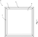
- FIG 1 shows a fenestration unit of an embodiment of the present invention generally indicated at 10, comprising an outer frame 12 with a hinge locator 14, illustrated in Figure 2 , mounted thereto.
- the fenestration unit 10 of this embodiment is suitable for a window, door or other type of fenestration, such as a vent or cladding panel.
- a sash 8 is moveably mounted within the outer frame 12.
- the term "closed position” refers to the position of the sash 8 when it is substantially coplanar with the outer frame 12.
- the open position refers to the position of the sash 8 when it is in any other position within the outer frame 12.
- the term “vertical” in this context refers to the direction perpendicular to the side of the outer frame 12 in contact with the hinge locator 14.
- the term “horizontal” refers to the direction parallel to the side of the outer frame 12 in contact with the hinge locator 14.
- the sash 8 comprises an inner frame 7 and a glazing unit 18.
- the sash 8 is beadless. That is, the glazing unit 18 is received within a fixed channel of the inner frame 7, and is fitted into the channel when three sides of the inner frame 7 are assembled. A fourth side of the inner frame 7 is then secured across the opening so the glazing unit 18 is held in place on all sides and cannot readily be removed from the inner frame 7.
- the inner frame may beaded, and the glazing unite 18 may be fitted transverse to the plane of the inner frame, before a bead is fitted to hold it in place.
- the sash 8 is connected to the outer frame 12 via a hinge mechanism 16, so that the sash is retained within the outer frame 12 whilst being moveable relative to the outer frame 12.
- the glazing unit 18 in this embodiment is a double glazing unit, alternative glazing units, for example triple glazing or opaque panels, for example for doors, may be used.
- Fenestration units 10 of this type are typically used in external walls of domestic and commercial buildings. It is therefore necessary that the fenestration unit meets requirements for thermal insulation, sealing against water ingress, draughts etc.
- the sash 8 and the outer frame 12 are metallic frames constructed from four members connected by mitre joints.
- a metallic sash as described here may include features or components of some non-metallic or composite material, such as plastics material or wood.
- the sash 8 may comprise external and internal aluminium profiles, which provide structural strength to the inner frame, with a thermal break of plastics or foam material sandwiched therebetween.
- the sash 8 and the outer frame 12 are aluminium.
- the sash 8 and the outer frame 12 of this embodiment comprise a 6063T6 aluminium alloy.
- any other suitable material may be used.
- the sash and the outer frame are of some other suitable material, such as some other 6063 series aluminium alloy, or a 6060 series aluminium alloy.
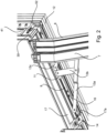
- Figure 2 is an isometric view of the fenestration unit 10 having a hinge locator system configured to position the hinge mechanism 16.
- the outer frame 12 comprises a first surface 17, configured to receive the hinge locator 14.
- the first surface 17 and a second surface 41 normal to the first are configured to receive a second locator 30 of the hinge locator system.
- the first surface 17 of the outer frame 12 is substantially horizontal in this embodiment.
- a relatively narrow groove or channel 17a is provided on the surface 17, and an aligned groove or channel (not visible) is provided on the second surface 41.
- the first groove 17a complements a corresponding mounting formation 44 on the hinge locator 14, and a corresponding mounting formation 46 on the second locator 30.
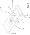
- FIG 3 is an enlarged view of the hinge locator 14 illustrated in Figure 2 .
- the hinge locator 14 comprises a body 19, a ramp portion 20 formed from the body and a first retaining formation 22, to receive the hinge mechanism 16.
- the body 19, the ramp portion 20 and the first retaining formation 22 are integral and the retaining formation is a recess. This reduces the number of parts necessary for manufacture and installation, and is also space efficient.
- the hinge locator 14 is manufactured from a plastics material, but in other embodiments may be metallic or another suitable material.
- the hinge locator 14 is manufactured using injection moulding, however any suitable manufacturing technique may be used.
- the ramp portion 20 of the hinge locator 14 comprises a first ramp section 24 and a second ramp section 26.
- the ramped surface of the first ramp section 24 is configured to be steeper in gradient than the ramped surface of the second ramp section 26, to aid the run-up process of the sash 8 into the closed position.
- the base surface of the first ramp section 24 is mounted within the first groove 17a upon assembly. This assists with its correct alignment and retention.
- the second ramp section 26 comprises a planar bottom surface configured to sit within the outer frame 12 on the surface 17.
- the first retaining formation 22 and a hole 28 extend from the top surface of the ramp section 26 to the base surface of the ramp section 26.
- the hole 28 is configured to receive a fastener.
- the hole 28 is countersunk to receive the head of a screw in a flush manner, as illustrated in Figure 2 .
- the first retaining formation 22 is located on a side surface of the hinge locator 14 that is adjacent to an inclined edge of the ramp portion 20.
- a second retaining formation 23 is located on the opposing side of the ramp portion 20 in the same equivalent position.
- the second retaining formation 23 makes the hinge locator 14 suitable for use on either side of the hinge mechanism 16, and therefore increases its versatility for both right hand and left hand opening sashes.
- the retaining formations 22, 23 are both recesses, each comprising two parallel sides, and a side perpendicular to the parallel sides that extend the full depth of the hinge locator. This arrangement is suitable for receiving the hinge mechanism 16 of Figure 2 , because the two ends of the hinge mechanism 16 are rectangular.
- the width of the retaining formation 22 is configured to be slightly wider than the width of the end of the hinge mechanism 16, to ensure the hinge mechanism 16 fits within the retaining formation 22, but that the movement of the hinge mechanism 16 within the retaining formation 22 is restricted.
- the two parallel sides restrict the movement of the hinge mechanism in a first axis extending between the parallel sides, the perpendicular side restricts the movement in an axis running perpendicular to the first axis, and the outer frame restricts the movement downwardly.
- the hinge mechanism 16 is correctly aligned in three directions when fitted therein.
- the body 19 of the hinge locator 14 comprises a planar top surface 50 that extends from a top edge of the ramp portion 20, parallel to the base surface that is mounted to the surface 17 of the outer frame 12. This configuration enables the sash 8 to sit upon the planar top surface 50 of the hinge locator 14 when the window is in its closed position, in the correct alignment.
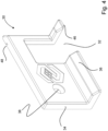
- FIG. 4 shows a perspective view of the second locator 30.
- the hinge locator 14 and the second locator 30 together make up the hinge locator system.
- the second locator 30 comprises a body 34 configured to be mounted to the outer frame 12, a third retaining formation 32 and a second ramp portion 36. Upon assembly, the second locator 30 engages with the end of the hinge mechanism 16 remote from the hinge locator 14.
- the second locator 30 is configured to be mounted to the outer frame 12 at a corner. The corner acts as a datum point and positions the second locator 30 correctly in two directions, which consequently aids the correct positioning of the hinge mechanism 16.
- the second locator 30 is manufactured from a plastics material, however it shall be appreciated that the second locator 30 may be manufactured using any suitable material, for example a metallic material.
- the second locator 14 is manufactured using injection moulding, however any suitable manufacturing technique may be used.
- the second locator 30 extends in two perpendicular directions to form a substantially L-shaped cross-section.
- a vertically extending section of the L-shape is longer than a horizontally extending section of the L-shape. This arrangement enables the second locator 30 to receive the end of the hinge mechanism 16 that has a vertical protrusion 52.
- the third retaining formation 32 extends in two perpendicular directions to form an L-shaped recess in the body 34 of the second locator 30.
- the third retaining formation 32 comprises two sets of parallel sides that are perpendicular to one another, and a side that is perpendicular to both sets of parallel lines to form an L-shape. This configuration restricts the movement and aids the correct positioning of the hinge mechanism 16 in three directions. Having the hinge locator 14 and the second locator 30 fixes the position of the hinge mechanism 16 and prevents it from sliding out of the retaining formation 22.
- the second locator 30 comprises a second mounting formation 48 to mount into the non-visible groove of the second surface 41 to aid retention and alignment of the second locator.
- the second ramp portion 36 extends from the horizontally extending section of the second locator 30.
- the horizontally extending section and the second ramp portion 36 are shorter than the total length of the first ramp portion 20 and the body 19. This is because there is more space available both at the location of the hinge locator 14 and in the orientation of the hinge locator 14.
- the second ramp portion 36 aids the correct positioning of the sash 8 by providing a run up.
- the second locator 30 comprises a countersunk bore 38 extending through the vertical section of the second locator 30 to receive a screw.
- the hinge mechanism 16 comprises a fixed component and at least one moveable arm.
- the fixed component of the hinge mechanism 16 of this embodiment is a track 9.
- a slidable member 11 allows the sash 8 to translate through the linear movement of the slidable member 11 within the track 9.
- the hinge mechanism 16 of this embodiment comprises a first, second and third arm 13a, 13b, and 13c.
- the arms 13a-c are configured in such a way as to allow a simultaneous pivoting and translational movement of the sash 8 as is known per se.
- the hinge locator 14 of the above embodiment is fitted within the outer frame 12 by mounting the mounting formation 44 within the first groove 17a of the outer frame 12 and securing it with the screw. This ensures the hinge locator 14 is correctly aligned within the outer frame 12.
- the hinge mechanism 16, which is mounted to the sash 8, is subsequently offered up to the outer frame 12 such that an end of the track 9 of the hinge mechanism 16 is located in the retaining formation 23.
- the second locator 30 is fitted to the corner of the sash 8 prior to the installation of the sash 8, so that the base surface of the second locator 30 and the base surface of the hinge locator 14 are positioned on the first surface 17 of the outer frame 12.
- the second end of the hinge mechanism 16 is retained in the third retaining formation 32. This provides positive location and support for the track 9 and for the sash 8.
- the hinge mechanism 16 is then fastened to the outer frame 12; in this embodiment using a screwdriver and screw. This permanent mounting is facilitated by the hinge locator system already aligning the track 9 in the correct location.
- a corresponding locating formation is provided on the opposing outer frame member so that a second hinge on a second side of the sash 8 may be located within that corresponding formation.
- the retaining formation may be a separate part that clips onto the body of the hinge locator.
- the retaining formation may be any suitable shape, for example triangular or rounded.
- the retaining formation may be any suitable means of retaining the hinge mechanism, for example a clamp.
- the hole in the ramp section of the hinge locator may be located in any position, for example extending from the top surface to the bottom surface of the body 19.
- the hole may be configured to receive any suitable form of fastener, for example a rivet.
- the hinge locator 14 may be mechanically fastened to the other frame 12 via a clip fit mechanism between the base surface of the hinge locator 14 and the outer frame 12. Any suitable non-mechanical fastening means may also be used, for example an adhesive.
- the second locator may comprise any suitable cross-section configured to position the second locator in a corner of the outer frame 12.
- the second locator 30 may be configured to sit at any suitable location within the outer frame, for example displaced from the corner.
- the second locator may be identical to the hinge locator and positioned at a remote end of the hinge mechanism.
- the hinge locator may also be used for mounting hinges of top hung windows that pivot about a horizontal axis.
- the hinge mechanism may comprise any number of arms configured in any suitable arrangement.
- a simple hinge mechanism may comprise a fixed component and a single pivotable arm.
Landscapes
- Engineering & Computer Science (AREA)
- Mechanical Engineering (AREA)
- Hinges (AREA)
Claims (15)
- Scharnier-Positionieranordnung eines Aufziehfensters (8), die dazu beschaffen ist, innerhalb eines Außenrahmens (12) einer Fenstereinheit (10) angeordnet zu werden, die Scharnier-Positionieranordnung umfassend:einen Scharniermechanismus (16), der eine feste Komponente (9) und einen Arm (13a) umfasst, der relativ zu der festen Komponente (9) schwenkbar ist, undeinen Scharnier-Positionsgeber (14) zum Einbau des Scharniermechanismus (16), umfassend:einen Körper (19), der einen Rampenabschnitt (20) bildet, der dazu beschaffen ist, innerhalb des Außenrahmens (12) der Fenstereinheit (10) montiert zu werden, so dass der Fensterflügel (8) während des Schließens in eine gewünschte Position geführt werden kann,eine Halteformation (22, 23) zum Aufnehmen eines ersten Endes der festen Komponente (9) des Scharniermechanismus (16), die aus dem Körper (19) geformt ist, unddadurch gekennzeichnet, dassdie Halteformation (22, 23) eine Vertiefung (22, 23) ist, die sich an einer Seitenfläche des Scharnier-Positionsgebers (14) befindet, die an eine geneigte Kante des Rampenabschnitts (20) angrenzt, und wobei eine Form der Vertiefung (22, 23) eine Form des ersten Endes der festen Komponente (9) des Scharniermechanismus (16) ergänzt.
- Scharnier-Positionieranordnung nach Anspruch 1, wobei sich die Halteformation (22, 23) auf einer Seitenfläche des Rampenabschnitts befindet und sich von einer oberen Fläche (50) des Rampenabschnitts (20) zu einer Basisfläche des Rampenabschnitts (20) erstreckt.
- Scharnier-Positionieranordnung nach Anspruch 1 oder Anspruch 2, wobei der Rampenabschnitt (20) und die Halteformation (22, 23) integral sind.
- Scharnier-Positionieranordnung nach einem der vorhergehenden Ansprüche, wobei der Scharnier-Positionsgeber (14) eine Bohrung (38) umfasst, die zur Aufnahme eines Befestigungselements beschaffen ist, wobei sich die Bohrung (38) optional auf einer oberen Fläche (50) des Scharnier-Positionsgebers (14) befindet und sich von einer oberen Kante des Rampenabschnitts (20) erstreckt.
- Scharnier-Positionieranordnung nach einem der vorhergehenden Ansprüche, wobei die Aussparung (22, 23) zwei parallele Seiten und eine senkrechte Seite umfasst.
- Scharnier-Positionieranordnung nach einem der vorhergehenden Ansprüche, wobei der Scharnier-Positionsgeber (14) eine zumindest teilweise ebene Unterseite, die so beschaffen ist, dass sie innerhalb des Außenrahmens (12) sitzt, und eine parallel zueinander verlaufende Oberseite (50), die sich vom Rampenabschnitt (20) erstreckt, aufweist.
- Scharnier-Positioniersystem zum Installieren eines Scharniermechanismus (16) innerhalb einer Fenstereinheit (10), umfassend:eine Scharnier-Positionieranordnung nach einem der vorhergehenden Ansprüche undein zweiter Positionsgeber (30), umfassend:einen Körper (34), der dazu beschaffen ist, an dem Außenrahmen (12) montiert zu werden, undeine zweite Halteformation (23), die dazu beschaffen ist, ein zweites Ende eines Scharniermechanismus (16) aufzunehmen.
- Scharnier-Positioniersystem nach Anspruch 7, wobei der zweite Positionsgeber (30) dazu beschaffen ist, an einer Ecke des Außenrahmens (12) angeordnet zu werden, die vom Scharnier-Positionsgeber (14) entfernt ist, wobei der zweite Positionsgeber (30) optional ein Loch aufweist, das dazu beschaffen ist, ein Befestigungselement aufzunehmen.
- Scharnier-Positionierungssystem nach einem der Ansprüche 7 oder 8, wobei der Körper (34) des zweiten Positionsgebers (30) dazu beschaffen ist, mit einer ersten Oberfläche (17) des Außenrahmens (12) und einer benachbarten zweiten Oberfläche (41) des Rahmens (12) in Eingriff zu kommen, wobei der zweite Positionsgeber (30) optional eine Rampenoberfläche umfasst.
- Fenstereinheitsanordnung (10) zur Installation in einer Öffnung, umfassend:einen Außenrahmen (12),einen relativ zum Außenrahmenelement (12) beweglichen Fensterflügel (8), umfassend:einen Innenrahmen (7) undeine Verglasungseinheit (18), undein Scharnier-Positionierungssystem nach einem der Ansprüche 7 bis 9.
- Fenstereinheitsanordnung (10) nach Anspruch 10, wobei der Scharniermechanismus (16) ferner dazu beschaffen ist, den Fensterflügel (8) relativ zum Außenrahmen (12) zu verschieben.
- Fenstereinheitsanordnung (10) nach einem der Ansprüche 10 oder 11, wobei ein zweites Scharnier-Positionierungssystem innerhalb des Außenrahmens (12) auf einer dem ersten Scharnier-Positionierungssystem gegenüberliegenden Seite montiert ist.
- Verfahren zum Installieren einer Verglasungseinheit (18) innerhalb eines Außenrahmens (12) einer Fenstereinheit (10), umfassend die Schritte:a) Anbringen des Scharnier-Positionsgebers (14) der Scharnier-Positionierungsanordnung nach einem der Ansprüche 1 bis 6 innerhalb des Außenrahmens (12),b) Anbringen eines Scharniermechanismus (16) der Scharnier-Positionierungsanordnung nach einem der Ansprüche 1 bis 6, der an einem Fensterflügel (8) montiert ist, an dem Außenrahmen (12), so dass sich ein Ende eines festen Teils (9) des Scharniermechanismus (16) in der Halteformation (22, 23) befindet, undc) Befestigen des festen Teils (9) des Scharniermechanismus (16) an dem Außenrahmen (9).
- Verfahren nach Anspruch 13, umfassend einen weiteren Schritt d) nach Schritt a), bei dem der zweite Positionsgeber (30) des Scharnier-Positioniersystems nach einem der Ansprüche 7 bis 9 in den Außenrahmen (12) eingesetzt wird.
- Verfahren nach Anspruch 14, umfassend einen weiteren Schritt e) nach Schritt b), bei dem ein zweites Ende des festen Teils (9) des Scharniermechanismus (16) in der zweiten Halteformation (32) des zweiten Positionsgebers (30) gehalten wird.
Applications Claiming Priority (1)
| Application Number | Priority Date | Filing Date | Title |
|---|---|---|---|
| GB2001092.2A GB2591992B (en) | 2020-01-27 | 2020-01-27 | A hinge locator |
Publications (3)
| Publication Number | Publication Date |
|---|---|
| EP3854971A1 EP3854971A1 (de) | 2021-07-28 |
| EP3854971B1 true EP3854971B1 (de) | 2024-10-02 |
| EP3854971C0 EP3854971C0 (de) | 2024-10-02 |
Family
ID=69725997
Family Applications (1)
| Application Number | Title | Priority Date | Filing Date |
|---|---|---|---|
| EP21153855.8A Active EP3854971B1 (de) | 2020-01-27 | 2021-01-27 | Scharnierortungsvorrichtung |
Country Status (2)
| Country | Link |
|---|---|
| EP (1) | EP3854971B1 (de) |
| GB (1) | GB2591992B (de) |
Family Cites Families (7)
| Publication number | Priority date | Publication date | Assignee | Title |
|---|---|---|---|---|
| GB2214230B (en) * | 1987-12-24 | 1992-01-08 | Cego Ltd | Window stays |
| GB2333122B (en) * | 1998-01-09 | 2002-06-26 | Dgs Hardware Ltd | Improvements in or relating to window supports |
| GB2398105B (en) * | 2000-08-10 | 2004-12-01 | Jurras Ltd | Friction stay |
| GB2374899B (en) * | 2001-04-26 | 2005-04-13 | Cotswold Architect Prod | Stays |
| DE102006005953C5 (de) * | 2006-02-09 | 2008-10-16 | Roto Frank Ag | Fenster, Tür oder dergleichen mit Mittelschließer |
| CN203769517U (zh) * | 2014-01-10 | 2014-08-13 | 广东澳利坚建筑五金有限公司 | 上悬窗用滑撑铰链 |
| DE102017207707B3 (de) * | 2017-05-08 | 2018-06-28 | Roto Frank Ag | Beschlaganordnung sowie Fenster oder Tür mit einer derartigen Beschlaganordnung |
-
2020
- 2020-01-27 GB GB2001092.2A patent/GB2591992B/en active Active
-
2021
- 2021-01-27 EP EP21153855.8A patent/EP3854971B1/de active Active
Also Published As
| Publication number | Publication date |
|---|---|
| EP3854971C0 (de) | 2024-10-02 |
| EP3854971A1 (de) | 2021-07-28 |
| GB2591992A (en) | 2021-08-18 |
| GB202001092D0 (en) | 2020-03-11 |
| GB2591992B (en) | 2024-10-09 |
Similar Documents
| Publication | Publication Date | Title |
|---|---|---|
| US20170268282A1 (en) | Fenestration supplement systems and methods of use | |
| US20190264485A1 (en) | Upwardly Pivoted Window with Spring Biased Sash | |
| CA3016612C (en) | Pre-hung doors and methods of installation therefor | |
| US20240011348A1 (en) | Fenestration unit with accessible ig space | |
| US8376019B2 (en) | Window assembly with movable interior sash | |
| EP3854971B1 (de) | Scharnierortungsvorrichtung | |
| US7765741B2 (en) | Movable light latch | |
| KR102428308B1 (ko) | 미서기창의 창짝 구조 | |
| US5784839A (en) | Easy to assemble window | |
| KR102393066B1 (ko) | 미서기창의 창짝 구조 | |
| GB2525183A (en) | Fenestration products | |
| CN214006952U (zh) | 一种门扇或窗扇 | |
| JP7826164B2 (ja) | 自動ドア | |
| JP7041019B2 (ja) | 建具 | |
| CN120592535B (zh) | 一种90度开启纱窗铰链的双内开窗 | |
| JP2026046666A (ja) | 折れ戸 | |
| JP2026046667A (ja) | 折れ戸および折れ戸の施工方法 | |
| EP4257385A1 (de) | Abdeckvorrichtung für fahrzeugfenster | |
| EP2933419B1 (de) | Fensterprodukte | |
| JP2026061375A (ja) | 建具 | |
| AU2021106920A4 (en) | Screening system | |
| JP2026046668A (ja) | 建具 | |
| JP2026061376A (ja) | 建具 | |
| JP3634017B2 (ja) | 連窓サッシ | |
| AU2024205717A1 (en) | Improved window stay and assembly |
Legal Events
| Date | Code | Title | Description |
|---|---|---|---|
| PUAI | Public reference made under article 153(3) epc to a published international application that has entered the european phase |
Free format text: ORIGINAL CODE: 0009012 |
|
| STAA | Information on the status of an ep patent application or granted ep patent |
Free format text: STATUS: THE APPLICATION HAS BEEN PUBLISHED |
|
| AK | Designated contracting states |
Kind code of ref document: A1 Designated state(s): AL AT BE BG CH CY CZ DE DK EE ES FI FR GB GR HR HU IE IS IT LI LT LU LV MC MK MT NL NO PL PT RO RS SE SI SK SM TR |
|
| STAA | Information on the status of an ep patent application or granted ep patent |
Free format text: STATUS: REQUEST FOR EXAMINATION WAS MADE |
|
| RAP3 | Party data changed (applicant data changed or rights of an application transferred) |
Owner name: GARNER ALUMINIUM EXTRUSIONS LIMITED |
|
| 17P | Request for examination filed |
Effective date: 20220128 |
|
| RBV | Designated contracting states (corrected) |
Designated state(s): AL AT BE BG CH CY CZ DE DK EE ES FI FR GB GR HR HU IE IS IT LI LT LU LV MC MK MT NL NO PL PT RO RS SE SI SK SM TR |
|
| STAA | Information on the status of an ep patent application or granted ep patent |
Free format text: STATUS: EXAMINATION IS IN PROGRESS |
|
| 17Q | First examination report despatched |
Effective date: 20240207 |
|
| GRAP | Despatch of communication of intention to grant a patent |
Free format text: ORIGINAL CODE: EPIDOSNIGR1 |
|
| STAA | Information on the status of an ep patent application or granted ep patent |
Free format text: STATUS: GRANT OF PATENT IS INTENDED |
|
| INTG | Intention to grant announced |
Effective date: 20240619 |
|
| GRAS | Grant fee paid |
Free format text: ORIGINAL CODE: EPIDOSNIGR3 |
|
| GRAA | (expected) grant |
Free format text: ORIGINAL CODE: 0009210 |
|
| STAA | Information on the status of an ep patent application or granted ep patent |
Free format text: STATUS: THE PATENT HAS BEEN GRANTED |
|
| AK | Designated contracting states |
Kind code of ref document: B1 Designated state(s): AL AT BE BG CH CY CZ DE DK EE ES FI FR GB GR HR HU IE IS IT LI LT LU LV MC MK MT NL NO PL PT RO RS SE SI SK SM TR |
|
| REG | Reference to a national code |
Ref country code: GB Ref legal event code: FG4D |
|
| REG | Reference to a national code |
Ref country code: CH Ref legal event code: EP |
|
| REG | Reference to a national code |
Ref country code: IE Ref legal event code: FG4D |
|
| REG | Reference to a national code |
Ref country code: DE Ref legal event code: R096 Ref document number: 602021019478 Country of ref document: DE |
|
| U01 | Request for unitary effect filed |
Effective date: 20241008 |
|
| U07 | Unitary effect registered |
Designated state(s): AT BE BG DE DK EE FI FR IT LT LU LV MT NL PT RO SE SI Effective date: 20241030 |
|
| U20 | Renewal fee for the european patent with unitary effect paid |
Year of fee payment: 5 Effective date: 20250116 |
|
| PG25 | Lapsed in a contracting state [announced via postgrant information from national office to epo] |
Ref country code: IS Free format text: LAPSE BECAUSE OF FAILURE TO SUBMIT A TRANSLATION OF THE DESCRIPTION OR TO PAY THE FEE WITHIN THE PRESCRIBED TIME-LIMIT Effective date: 20250202 Ref country code: HR Free format text: LAPSE BECAUSE OF FAILURE TO SUBMIT A TRANSLATION OF THE DESCRIPTION OR TO PAY THE FEE WITHIN THE PRESCRIBED TIME-LIMIT Effective date: 20241002 |
|
| PG25 | Lapsed in a contracting state [announced via postgrant information from national office to epo] |
Ref country code: ES Free format text: LAPSE BECAUSE OF FAILURE TO SUBMIT A TRANSLATION OF THE DESCRIPTION OR TO PAY THE FEE WITHIN THE PRESCRIBED TIME-LIMIT Effective date: 20241002 |
|
| PG25 | Lapsed in a contracting state [announced via postgrant information from national office to epo] |
Ref country code: NO Free format text: LAPSE BECAUSE OF FAILURE TO SUBMIT A TRANSLATION OF THE DESCRIPTION OR TO PAY THE FEE WITHIN THE PRESCRIBED TIME-LIMIT Effective date: 20250102 |
|
| PG25 | Lapsed in a contracting state [announced via postgrant information from national office to epo] |
Ref country code: GR Free format text: LAPSE BECAUSE OF FAILURE TO SUBMIT A TRANSLATION OF THE DESCRIPTION OR TO PAY THE FEE WITHIN THE PRESCRIBED TIME-LIMIT Effective date: 20250103 |
|
| PG25 | Lapsed in a contracting state [announced via postgrant information from national office to epo] |
Ref country code: CZ Free format text: LAPSE BECAUSE OF FAILURE TO SUBMIT A TRANSLATION OF THE DESCRIPTION OR TO PAY THE FEE WITHIN THE PRESCRIBED TIME-LIMIT Effective date: 20241002 Ref country code: PL Free format text: LAPSE BECAUSE OF FAILURE TO SUBMIT A TRANSLATION OF THE DESCRIPTION OR TO PAY THE FEE WITHIN THE PRESCRIBED TIME-LIMIT Effective date: 20241002 |
|
| PG25 | Lapsed in a contracting state [announced via postgrant information from national office to epo] |
Ref country code: RS Free format text: LAPSE BECAUSE OF FAILURE TO SUBMIT A TRANSLATION OF THE DESCRIPTION OR TO PAY THE FEE WITHIN THE PRESCRIBED TIME-LIMIT Effective date: 20250102 |
|
| PG25 | Lapsed in a contracting state [announced via postgrant information from national office to epo] |
Ref country code: SM Free format text: LAPSE BECAUSE OF FAILURE TO SUBMIT A TRANSLATION OF THE DESCRIPTION OR TO PAY THE FEE WITHIN THE PRESCRIBED TIME-LIMIT Effective date: 20241002 |
|
| PG25 | Lapsed in a contracting state [announced via postgrant information from national office to epo] |
Ref country code: SK Free format text: LAPSE BECAUSE OF FAILURE TO SUBMIT A TRANSLATION OF THE DESCRIPTION OR TO PAY THE FEE WITHIN THE PRESCRIBED TIME-LIMIT Effective date: 20241002 |
|
| PLBE | No opposition filed within time limit |
Free format text: ORIGINAL CODE: 0009261 |
|
| STAA | Information on the status of an ep patent application or granted ep patent |
Free format text: STATUS: NO OPPOSITION FILED WITHIN TIME LIMIT |
|
| REG | Reference to a national code |
Ref country code: CH Ref legal event code: PL |
|
| 26N | No opposition filed |
Effective date: 20250703 |
|
| PG25 | Lapsed in a contracting state [announced via postgrant information from national office to epo] |
Ref country code: MC Free format text: LAPSE BECAUSE OF FAILURE TO SUBMIT A TRANSLATION OF THE DESCRIPTION OR TO PAY THE FEE WITHIN THE PRESCRIBED TIME-LIMIT Effective date: 20241002 |
|
| PG25 | Lapsed in a contracting state [announced via postgrant information from national office to epo] |
Ref country code: CH Free format text: LAPSE BECAUSE OF NON-PAYMENT OF DUE FEES Effective date: 20250131 |
|
| PG25 | Lapsed in a contracting state [announced via postgrant information from national office to epo] |
Ref country code: IE Free format text: LAPSE BECAUSE OF NON-PAYMENT OF DUE FEES Effective date: 20250127 |
|
| U20 | Renewal fee for the european patent with unitary effect paid |
Year of fee payment: 6 Effective date: 20260115 |
|
| PGFP | Annual fee paid to national office [announced via postgrant information from national office to epo] |
Ref country code: GB Payment date: 20260116 Year of fee payment: 6 |