EP3854640A1 - Testing device for an airbag module - Google Patents
Testing device for an airbag module Download PDFInfo
- Publication number
- EP3854640A1 EP3854640A1 EP20178227.3A EP20178227A EP3854640A1 EP 3854640 A1 EP3854640 A1 EP 3854640A1 EP 20178227 A EP20178227 A EP 20178227A EP 3854640 A1 EP3854640 A1 EP 3854640A1
- Authority
- EP
- European Patent Office
- Prior art keywords
- lid
- airbag
- testing device
- support structure
- fastened
- Prior art date
- Legal status (The legal status is an assumption and is not a legal conclusion. Google has not performed a legal analysis and makes no representation as to the accuracy of the status listed.)
- Granted
Links
Images
Classifications
-
- B—PERFORMING OPERATIONS; TRANSPORTING
- B60—VEHICLES IN GENERAL
- B60R—VEHICLES, VEHICLE FITTINGS, OR VEHICLE PARTS, NOT OTHERWISE PROVIDED FOR
- B60R21/00—Arrangements or fittings on vehicles for protecting or preventing injuries to occupants or pedestrians in case of accidents or other traffic risks
- B60R21/02—Occupant safety arrangements or fittings, e.g. crash pads
- B60R21/16—Inflatable occupant restraints or confinements designed to inflate upon impact or impending impact, e.g. air bags
-
- G—PHYSICS
- G01—MEASURING; TESTING
- G01M—TESTING STATIC OR DYNAMIC BALANCE OF MACHINES OR STRUCTURES; TESTING OF STRUCTURES OR APPARATUS, NOT OTHERWISE PROVIDED FOR
- G01M17/00—Testing of vehicles
- G01M17/007—Wheeled or endless-tracked vehicles
- G01M17/0078—Shock-testing of vehicles
-
- G—PHYSICS
- G01—MEASURING; TESTING
- G01M—TESTING STATIC OR DYNAMIC BALANCE OF MACHINES OR STRUCTURES; TESTING OF STRUCTURES OR APPARATUS, NOT OTHERWISE PROVIDED FOR
- G01M17/00—Testing of vehicles
- G01M17/007—Wheeled or endless-tracked vehicles
-
- B—PERFORMING OPERATIONS; TRANSPORTING
- B60—VEHICLES IN GENERAL
- B60R—VEHICLES, VEHICLE FITTINGS, OR VEHICLE PARTS, NOT OTHERWISE PROVIDED FOR
- B60R21/00—Arrangements or fittings on vehicles for protecting or preventing injuries to occupants or pedestrians in case of accidents or other traffic risks
- B60R21/02—Occupant safety arrangements or fittings, e.g. crash pads
- B60R21/16—Inflatable occupant restraints or confinements designed to inflate upon impact or impending impact, e.g. air bags
- B60R21/20—Arrangements for storing inflatable members in their non-use or deflated condition; Arrangement or mounting of air bag modules or components
- B60R21/215—Arrangements for storing inflatable members in their non-use or deflated condition; Arrangement or mounting of air bag modules or components characterised by the covers for the inflatable member
-
- G—PHYSICS
- G01—MEASURING; TESTING
- G01L—MEASURING FORCE, STRESS, TORQUE, WORK, MECHANICAL POWER, MECHANICAL EFFICIENCY, OR FLUID PRESSURE
- G01L17/00—Devices or apparatus for measuring tyre pressure or the pressure in other inflated bodies
-
- G—PHYSICS
- G01—MEASURING; TESTING
- G01L—MEASURING FORCE, STRESS, TORQUE, WORK, MECHANICAL POWER, MECHANICAL EFFICIENCY, OR FLUID PRESSURE
- G01L5/00—Apparatus for, or methods of, measuring force, work, mechanical power, or torque, specially adapted for specific purposes
- G01L5/0052—Apparatus for, or methods of, measuring force, work, mechanical power, or torque, specially adapted for specific purposes measuring forces due to impact
-
- G—PHYSICS
- G01—MEASURING; TESTING
- G01M—TESTING STATIC OR DYNAMIC BALANCE OF MACHINES OR STRUCTURES; TESTING OF STRUCTURES OR APPARATUS, NOT OTHERWISE PROVIDED FOR
- G01M7/00—Vibration-testing of structures; Shock-testing of structures
- G01M7/08—Shock-testing
-
- G—PHYSICS
- G01—MEASURING; TESTING
- G01M—TESTING STATIC OR DYNAMIC BALANCE OF MACHINES OR STRUCTURES; TESTING OF STRUCTURES OR APPARATUS, NOT OTHERWISE PROVIDED FOR
- G01M99/00—Subject matter not provided for in other groups of this subclass
- G01M99/008—Subject matter not provided for in other groups of this subclass by doing functionality tests
Definitions
- the present disclosure relates to a testing device for an airbag module.
- the airbags of a vehicle are arranged in a folded way inside an airbag module located invisibly to the vehicle passenger.
- the instrument panel comprises an airbag cover, also referred to as airbag flap closing a chute channel mainly defined by the airbag module.
- the airbag module comprises a gas generator that when triggered provides high pressure gas that is introduced into the airbag which is thereby inflated.
- the airbag cover of the instrument panel is subsequently torn open, so that the airbag can enter the passenger compartment where it inflates to its maximum size to protect the passenger in case of an accident.
- a dynamic interaction is created between the airbag cover and the airbag exiting the chute channel.
- DE 10 2005 020 217 A1 discloses a testing device for an airbag system in which the airbag module is located behind an airbag cover delimited by cut-outs from the rest of the instrument panel. The cut-outs only partially penetrate the outer layer and the inner layer of the instrument panel and thus form breakage points at which the airbag cover is released from the instrument panel during an airbag shot. After testing the test device has to be costly repaired or completely replaced.
- the testing device comprises a plate to which an airbag module containing an airbag can be fastened, the plate forming a passage which can be penetrated by the airbag, a lid rotatably fastened to the plate between a closing position in which the lid closes the passage and an open position in which the passage is opened, and a closure device that closes the lid in the closing position.
- the angle the lid is forming with the plate in the initial position can be adjusted by cantilever beams. This angle and the angular velocity of the lid are used to simulate different installation situation of the instrument panel.
- testing device according to DE 10 2012 013 893 A1 is only partially be suited to simulate the installation situation of different instrument panels.
- testing device which delivers cost-efficient and reliable results by which airbag systems can be optimized considering a given instrument panel and a given installation situation without destroying the testing device. Moreover, it is one task of one embodiment of the present disclosure to present a testing device able to identify the airbag module out of a plurality of available airbag modules that works best with a given instrument panel.
- the testing device for an airbag module comprises a support structure to which an airbag module containing an airbag can be fastened, the support structure forming a passage which can be penetrated by the airbag, at least one lid movably fastened to the support structure by fastening means between a closing position in which the lid closes the passage and an open position in which the passage is opened, and a closure device that closes the lid in the closing position by applying a closing force to the lid, wherein the lid comprises a number of first force sensors measuring the opening force applied to the lid by the airbag when moved out of the closed position by the airbag.
- the main difference between the testing device according to the present application and the testing devices known from the prior art is that the lid is or the lids are provided with one or more first force sensors. It was found under constant conditions by using the opening force applied that different airbag modules can be compared to each other and the lid when the airbag module is triggered and the airbag inflated. It is not necessary to use a real instrument panel.
- the testing device can be re-used after one test without significant effort.
- the passage simulates at least a part of a chute channel guiding the airbag upon inflation. Differences between the tested airbag modules can be identified.
- the lid comprises at least one accelertion sensor measuring the acceleration of the lid when moved out of the closed position by the airbag.
- the acceleration sensor can measure accelerations in three axes. Thereby the direction of the lid movement in correlation with the forces measured by the force sensors can be evaluated.
- the processes upon airbag inflation can be described in more detail and with a higher accuracy.
- the data obtained by the airbag sensor supports the evaluation of the testing device.
- the lid is fastened to the support structure by a number of flexible belts, the belts cooperating with a number of second force sensors measuring the hinge force applied to the belts when the lid is moved out of the closed position by the airbag.
- the belts serve for simulating the movement of the airbag cover of a given instrument panel.
- the lid is fastened to the support plate by means of a hinge joint defining a rotation axis around which the lid moves when the airbag is triggered.
- the airbag cover of a given instrument panel does not rotate around a well-defined rotation axis when the airbag is triggered.
- the lid is fastened to the support structure such that they form a hinge-like structure.
- the airbag cover is fastened to the remaining instrument panel by a hinge-like connection.
- the belts to simulate the way the airbag cover is fastened to the instrument panel.
- the flexibility can be chosen such that the movement of the airbag cover can be simulated better compared to known testing devices. The quality of the results can thereby be increased.
- the second force sensors generate an information on the forces acting on the belts.
- the information generated by the second force sensors can be used for the layout of the connection between the airbag cover and the instrument panel.
- the belts at least partially enclose the lid. It was found that the fixation of the lid is better when the belts at least partially enclose the lid. The quality of the results can be further improved.
- the testing device comprises a first lid that is fastened to the support structure by a first fastening means and a second lid that is fastened to the support structure by a second fastening means.
- the testing device is amongst other reasons used to identify the airbag module out of a plurality of available airbag modules that works best with a given instrument panel.
- An increasing number of instrument panels have two or more airbag covers per airbag module, mainly for following reasons: Compared to instrument panels having one airbag cover per airbag module the airbag covers of instrument panels comprising two or more airbag covers per airbag module are smaller in size. As a consequence the weight of one airbag cover is also smaller such that the energy the airbag has to impose on the airbag cover for opening is smaller.
- the influence of the covers on the inflation of the airbag is smaller. Moreover, some of the airbag modules are placed in the vicinity of vehicle components like windscreens. The bigger the airbag cover is the more likely they will impinge on the vehicle components upon opening. The inflation of the airbag may thus be negatively effected. Thus the arrangement of the airbag module within the instrument panel is subject to certain limits. When the airbag covers are smaller these limits are also reduced. As a consequence the freedom of choice regarding the arrangement of the airbag module within the instnrument panel is enhanced.
- the testing device comprises means for adjusting the closing force.
- the possibility to adjust the closing force also serves for better simulating the movement of the airbag cover in case the airbag is triggered.
- the means comprise a number of magnets acting between the support structure and the closure device.
- the magnets in particular permanent magnets, provide the possibility to adjust the closing force very easily. It is also possible to change the closing force in the course of the movement of the lid such that the simulation of the movement of the airbag cover of a given instrument can be improved.
- the lid is at least partially made of carbon fiber reinforced plastic.
- the use of carbon fiber reinforced plastic enables a lightweight layout of the lid at high rigidity.
- the weight of the lid also has a big impact on the forces acting between the airbag and the airbag cover so a lightweight layout also contributes for an improved simulation of the opening process of the airbag cover when the airbag is triggered.
- the testing device comprises a high-speed camera.
- a high-speed camera facilitates following the movement of the lid and the way the airbag is inflated. Starting points to improve the inflation of the airbag may be identified by using the high-speed camera.
- the lid is at least partially made of a transparent material.
- the way the airbag inflates before or during its interaction with the lid can be followed.
- the testing device comprises a catchment device for receiving the lid in the open position.
- the catchment device may comprise a dampening element such as a cushion or an air buffer.
- the lid is moved very quickly when the airbag is inflated.
- the catchment device serves for absorbing the kinetic energy of the lid to prevent the damage or destruction of the lid and the support structure. Moreover, noisy impacts of the lid on the support structure are prevented.
- the support structure comprises a number of standardized mounting points for fastening the airbag module to the support structure.
- the majority of airbag modules available in the marked comprise standardized fixing points by which they are fixed to the instrument panel or other structures of the vehicle.
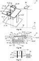
- the testing device 10 1 comprises a support structure 16 which is composed of a bearing plate 18, a number of pillars 20 fastened to the bearing plate 18 and a work plate 22 that rests on the pillars 20.
- the work plate 22 forms a passage 24 which has a substantially rectangular cross section.
- the testing device 10 1 comprises one lid 26 that is movably fastened to the work plate 22 by fastening means 27 embodied as a number of flexible belts 28. As evident from Figure 1B the belts 28 enclose the lid 26.
- the lid 26 can be moved between a closing position (see Figure 1B ) in which the lid 26 closes the passage 24 and an open position in which the lid 26 clears the passage 24 ( Figure 1A ).
- the belts 28 define the movement of the lid 26 between the closing position and the open position.
- the belts 28 provide a hinge-like fasteining of the lid 26 to the support structure 16.
- the movement of the lid 26 which is approximately a rotational movement, is indicated by the arrow P1 in Figure 1B .
- the testing device 10 1 further comprises a closure device 30 which applies a closing force FC to the lid 26 when the lid 26 is in the closing positon.
- the closure device 30 comprises a first plate 32 and a second plate 34 that are movably connected to each other by a hinge joint 36.
- the first plate 32 is fixedly connected to the work plate 22 whereas the second plate 34 may be moved in a position in which it is partially overlapping the passage 24.
- the testing device 10 1 is equipped with means 38 by which the closing force FC applied by the closure device 30 may be adjusted.
- the means 38 comprise a magnet 40, in particular a permanent magnet 40 arranged in the second plate 34 of the closure device 30 that interacts with the work plate 22 that is made of metal, thereby creating the closing force FC that keeps the lid 26 in the closing position.
- the magnet 40 may be changed for adjusting the closing force FC.
- the magnet 40 may be a permanent magnet such that the force acting between the lid 26 and the work plate 22 can be adjusted depending on the current applied.
- testing device 10 1 is equipped with a catchment device 42 ( Figure 1A ) which defines the open position of the lid 26 and comprises dampening elements 44 such as a cushion or an air buffer to avoid a hard impact of the lid 26 when reaching the open position.
- the testing device 10 1 is provided with a high-speed camera 46 by which the movement of the lid 26 and the inflation of the airbag 14 may be followed.
- Figure 1C separately shows the lid 26 by means of a bottom view such that the surface facing to the airbag module 12 in the closing position is visible.
- the lid 26 is provided with a number of first force sensors 48, in this case with a variable number of first force sensors 48.
- first force sensors 48 can be varied according to the relevant requirement. Beyond that the lid 26 is provided with one acceleration sensor 61. Again, the number of acceleration sensors can be varied if beneficial.
- the lid 26 is made of carbon fiber reinforced plastic 50 which is symbolized by the crosshatching of area A of the lid 26 that is separately illustrated in a magnified way. It is possible to provide the lid 26 with transparent sections such that one may through the lid 26 and see the folded airbag 14 when the lid 26 is in the closing position.
- the testing device 10 1 comprises second force sensors 52 that interact with the belts 28.
- the support structure 16 is equipped with a number of mounting points 54 by which the airbag module 12 may be fastened to the work plate 22.
- the airbag module 12 is fastened to the work plate 22 by means of screws (not shown).
- the mounting points 54 are standardized such that the majority of airbag modules 12 available in the marked may be fastened to the work plate 22 without further adjustments.
- a computer 56 is connected to the first force sensors 48, the second force sensors 52 and the high-speed camera 46 by means of cables 58. A wireless connection may also be conceivable.
- the computer 56 may also be connected to the airbag module 12, the permanent magnet and other components of the testing device 10 1 (not shown).
- the testing device 10 1 is used as follows: In the initial state that is shown in Figure 1B the lid 26 is in the closing position.
- the second plate 34 of the closure device 30 is flush with the first plate 32 and keeps the lid 26 in the closing position by means of the closing force FC generated by the magnet 40 arranged in the second plate 34 and interacting with the work plate 22.
- the airbag module 12 is now triggered, e.g. by a corresponding signal generated by the computer 56.
- a gas generator 60 of the airbag module 12 generates pressurized gas which is introduced into the airbag 14, thereby inflating the airbag 14.
- the opening force FO the airbag 14 imposes on the lid 26 is measured by the first force sensors 48.
- a variable number of force sensors are arranged on the lid 26 the force distribution over the lid 26 may be determined.
- the lid 26 moves into the open position, thereby moving the second plate 34 of the closure device 30 relative to the first plate 32 as indicated by the arrow P2 in Figure 1B .
- the lid 26 In the open position the lid 26 is received by the catchment device 42 as approximately shown in Figure 1A .
- the airbag 14 is not shown in Figure 1A .
- the bulk of the airbag 14 penetrates the passage 24 such that the airbag 14 can be fully inflated above the work plate 22.
- the testing device 10 1 reaches its final state once the airbag 14 is deflated after full inflation.
- the deflated airbag 14 and the triggered airbag module 12 can easily be removed and be replaced by an untriggered airbag module 12.
- the lid 26 and the second plate 34 may be moved back to the initial state as shown in Figure 1B without significant effort.
- the movement of the airbag 14, of the lid 26 and of the second plate 34 during the inflation of the airbag 14 may be monitored by the high-speed camera 46.
- the forces acting on the belts 28 during the inflation may be measured by the second force sensors 52. These forces are referred to as hinge forces FH.
- the hinge forces FH are an important parameter to estimate whether the airbag cover will stick to the instrument panel or not when the airbag inflates.
- the opening forces FO the airbag 14 imposes on the lid 26 can be measured by the first force sensors 48.
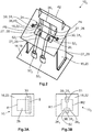
- Figure 2 shows a perspective principle view of a second embodiment of the testing device 10 2 .
- the basic construction of the testing device 10 2 according to the second embodiment is the same as of the testing device 10 1 of the first embodiment. Thus, only the differences will be discussed in the following.
- the passage 24 of the support structure 16 is covered by a first lid 26 1 and a second lid 26 2 .
- the first lid 26 1 is fastened to the support structure 16 by two first fastening means 27 1 whereas the second lid 26 2 is fastened to the support structure 16 by two second fastening means 27 2 .
- the fastening means 27 1 , 27 2 can be designed as described with reference to the first embodiment.
- the way the first lid 26 1 moves when the airbag 14 is inflating is indicated by the arrow P4.
- first fastening means 27 1 is equipped with a first group of second force sensors 52 1 while the second fastening means 27 2 comprises a second group of second force sensors 52 2 .
- each group 52 1 , 52 2 consists of two second force sensors 52.
- the number of second force sensors 52 can be varied if considered beneficial.
- the closure device 30 comprises a first sub-unit 31 1 and a second sub-unit 31 2 . They are arranged such that they partially cover the first lid 26 1 and the second lid 26 2 when in the closing position. The way the second sub-unit 31 2 is moving when the airbag 14 is inflating is indicated by the arrow P5.
- the computer 56 and the cables 58 are not shown.
- the accelerations and forces acting on the first lid 26 1 and the second lid 26 2 can be detected and analyzed in the same way as described for the first embodiment.
- One difference is that the behavior of the first lid 26 1 and the second lid 26 2 can be detected independent of each other.
- Figure 3A is a streamlined top view on the first embodiment of the testing device 10 1 .
- Figure 3B is a streamlined top view on the second embodiment of the testing device 10 2 .
- a pivot axis R for the lid 26, a first pivot axis R1 for the first lid 26 1 and a second pivot axis R2 for the second lid 26 2 are indicated by a solid line.
- the dashed line indicates the contact areas by which the lid, the first lid 26 1 and the second lid 26 2 are contacting or at least almost contacting the work plate 22 when in the closing position. While the contact area of the first embodiment of the testing device 10 1 is approximately U-shaped, the contact area of the second embodiment of the testing device 10 2 is approximately H-shaped.
Landscapes
- Physics & Mathematics (AREA)
- General Physics & Mathematics (AREA)
- Engineering & Computer Science (AREA)
- Mechanical Engineering (AREA)
- Air Bags (AREA)
Abstract
Description
- The present disclosure relates to a testing device for an airbag module.
- The airbags of a vehicle, in particular the passenger airbag, are arranged in a folded way inside an airbag module located invisibly to the vehicle passenger. In case of passenger airbags they are mounted behind the instrument panel. The instrument panel comprises an airbag cover, also referred to as airbag flap closing a chute channel mainly defined by the airbag module. The airbag module comprises a gas generator that when triggered provides high pressure gas that is introduced into the airbag which is thereby inflated. The airbag cover of the instrument panel is subsequently torn open, so that the airbag can enter the passenger compartment where it inflates to its maximum size to protect the passenger in case of an accident. When triggered a dynamic interaction is created between the airbag cover and the airbag exiting the chute channel.
- In order to achieve optimum functionality for the airbag in case of an accident it is necessary that the airbag system is adapted to the installation situation of the instrument panel. To develop optimized airbag systems expensive development processes including the instrument panels thus need to be carried out.
- Good test results can be generated by using prototype instrument panels. However, the use of prototype instruments is very costly since in each test the airbag cover of the instrument panel is torn open and thus the instrument panel destroyed so that it cannot be used for further tests anymore.
DE 10 2005 020 217 A1 discloses a testing device for an airbag system in which the airbag module is located behind an airbag cover delimited by cut-outs from the rest of the instrument panel. The cut-outs only partially penetrate the outer layer and the inner layer of the instrument panel and thus form breakage points at which the airbag cover is released from the instrument panel during an airbag shot. After testing the test device has to be costly repaired or completely replaced. -
DE 10 2012 013 893 A1 discloses a testing device for an airbag module which can be used without the need of employing an instrument panel. The testing device comprises a plate to which an airbag module containing an airbag can be fastened, the plate forming a passage which can be penetrated by the airbag, a lid rotatably fastened to the plate between a closing position in which the lid closes the passage and an open position in which the passage is opened, and a closure device that closes the lid in the closing position. The angle the lid is forming with the plate in the initial position can be adjusted by cantilever beams. This angle and the angular velocity of the lid are used to simulate different installation situation of the instrument panel. - However, the testing device according to
DE 10 2012 013 893 A1 - Further testing devices are disclosed in
CN 202710330 U ,KR 2005 0029838 A1 KR 2008 0026815 A1 - It is one task of one embodiment of the present disclosure to present a testing device which delivers cost-efficient and reliable results by which airbag systems can be optimized considering a given instrument panel and a given installation situation without destroying the testing device. Moreover, it is one task of one embodiment of the present disclosure to present a testing device able to identify the airbag module out of a plurality of available airbag modules that works best with a given instrument panel.
- The task is solved by the features specified in
claim 1. Advantageous embodiments are the subject of the dependent claims. - According to an embodiment the testing device for an airbag module comprises a support structure to which an airbag module containing an airbag can be fastened, the support structure forming a passage which can be penetrated by the airbag, at least one lid movably fastened to the support structure by fastening means between a closing position in which the lid closes the passage and an open position in which the passage is opened, and a closure device that closes the lid in the closing position by applying a closing force to the lid, wherein the lid comprises a number of first force sensors measuring the opening force applied to the lid by the airbag when moved out of the closed position by the airbag.
- For the sake of conciseness reference is made to one lid only in the following. However, the description equally applies to embodiments comprising two or more lids.
- The main difference between the testing device according to the present application and the testing devices known from the prior art is that the lid is or the lids are provided with one or more first force sensors. It was found under constant conditions by using the opening force applied that different airbag modules can be compared to each other and the lid when the airbag module is triggered and the airbag inflated. It is not necessary to use a real instrument panel. The testing device can be re-used after one test without significant effort. The passage simulates at least a part of a chute channel guiding the airbag upon inflation. Differences between the tested airbag modules can be identified.
- According to another embodiment the lid comprises at least one accelertion sensor measuring the acceleration of the lid when moved out of the closed position by the airbag. The acceleration sensor can measure accelerations in three axes. Thereby the direction of the lid movement in correlation with the forces measured by the force sensors can be evaluated. The processes upon airbag inflation can be described in more detail and with a higher accuracy. The data obtained by the airbag sensor supports the evaluation of the testing device.
- In a further embodiment the lid is fastened to the support structure by a number of flexible belts, the belts cooperating with a number of second force sensors measuring the hinge force applied to the belts when the lid is moved out of the closed position by the airbag. The belts serve for simulating the movement of the airbag cover of a given instrument panel. In the testing device disclosed in
DE 10 2012 013 893 A1DE 10 2012 013 893 A1 - Moreover, it is possible to fasten the lid to the support structure such that they form a hinge-like structure. In the vehicle the airbag cover is fastened to the remaining instrument panel by a hinge-like connection. In particular by means of the belts to simulate the way the airbag cover is fastened to the instrument panel.
- Belts of different flexibility are available in the market. The flexibility can be chosen such that the movement of the airbag cover can be simulated better compared to known testing devices. The quality of the results can thereby be increased.
- Moreover, the second force sensors generate an information on the forces acting on the belts. In order to avoid injury of the passengers of the vehicle it is of high significance that the airbag cover does not come loose. The information generated by the second force sensors can be used for the layout of the connection between the airbag cover and the instrument panel.
- In another embodiment the belts at least partially enclose the lid. It was found that the fixation of the lid is better when the belts at least partially enclose the lid. The quality of the results can be further improved.
- In accordance with another embodiment the testing device comprises a first lid that is fastened to the support structure by a first fastening means and a second lid that is fastened to the support structure by a second fastening means. As mentioned above, the testing device is amongst other reasons used to identify the airbag module out of a plurality of available airbag modules that works best with a given instrument panel. An increasing number of instrument panels have two or more airbag covers per airbag module, mainly for following reasons: Compared to instrument panels having one airbag cover per airbag module the airbag covers of instrument panels comprising two or more airbag covers per airbag module are smaller in size. As a consequence the weight of one airbag cover is also smaller such that the energy the airbag has to impose on the airbag cover for opening is smaller. The influence of the covers on the inflation of the airbag is smaller. Moreover, some of the airbag modules are placed in the vicinity of vehicle components like windscreens. The bigger the airbag cover is the more likely they will impinge on the vehicle components upon opening. The inflation of the airbag may thus be negatively effected. Thus the arrangement of the airbag module within the instrument panel is subject to certain limits. When the airbag covers are smaller these limits are also reduced. As a consequence the freedom of choice regarding the arrangement of the airbag module within the instnrument panel is enhanced.
- In a further embodiment the testing device comprises means for adjusting the closing force. The possibility to adjust the closing force also serves for better simulating the movement of the airbag cover in case the airbag is triggered.
- In another embodiment the means comprise a number of magnets acting between the support structure and the closure device. The magnets, in particular permanent magnets, provide the possibility to adjust the closing force very easily. It is also possible to change the closing force in the course of the movement of the lid such that the simulation of the movement of the airbag cover of a given instrument can be improved.
- In a further embodiment the lid is at least partially made of carbon fiber reinforced plastic. The use of carbon fiber reinforced plastic enables a lightweight layout of the lid at high rigidity. The weight of the lid also has a big impact on the forces acting between the airbag and the airbag cover so a lightweight layout also contributes for an improved simulation of the opening process of the airbag cover when the airbag is triggered.
- In another embodiment the testing device comprises a high-speed camera. A high-speed camera facilitates following the movement of the lid and the way the airbag is inflated. Starting points to improve the inflation of the airbag may be identified by using the high-speed camera.
- In a further embodiment the lid is at least partially made of a transparent material. In particular when using a high-speed camera the way the airbag inflates before or during its interaction with the lid can be followed.
- In another embodiment the testing device comprises a catchment device for receiving the lid in the open position. The catchment device may comprise a dampening element such as a cushion or an air buffer. The lid is moved very quickly when the airbag is inflated. The catchment device serves for absorbing the kinetic energy of the lid to prevent the damage or destruction of the lid and the support structure. Moreover, noisy impacts of the lid on the support structure are prevented.
- In a further embodiment the support structure comprises a number of standardized mounting points for fastening the airbag module to the support structure. The majority of airbag modules available in the marked comprise standardized fixing points by which they are fixed to the instrument panel or other structures of the vehicle. By using standardized mounting points many airbag modules can be fastened to the support structure of the present testing device without the need to adjust the testing device. The testing device is thus very versatile.
- The present disclosure is described in detail with reference to the drawings attached wherein
- Figure 1A
- is a principle perspective sketch of a first embodiment of a testing device according to the present application,
- Figure 1B
- is a principle partial sectional and not scaled view through the testing device shown in
Figure 1A , - Figure 1C
- is a separate not scaled bottom view of the lid of the testing device shown in
Figures 1A and 1B , - Figure 2
- is a principle perspective sketch of a first embodiment of a testing device according to the present application,
- Figure 3A
- is a principle and streamlined top view on the testing device according to the first embodiment, and
- Figure 3B
- is a principle and streamlined top view on the testing device according to the second embodiment.
- The following description relates to
Figures 1A and 1B which both show an embodiment of atesting device 101 for testing anairbag module 12 hosting a folded airbag 14 (seeFigure 1B ). Thetesting device 101 comprises a support structure 16 which is composed of a bearing plate 18, a number of pillars 20 fastened to the bearing plate 18 and a work plate 22 that rests on the pillars 20. The work plate 22 forms apassage 24 which has a substantially rectangular cross section. Furthermore thetesting device 101 comprises onelid 26 that is movably fastened to the work plate 22 by fastening means 27 embodied as a number of flexible belts 28. As evident fromFigure 1B the belts 28 enclose thelid 26. Thelid 26 can be moved between a closing position (seeFigure 1B ) in which thelid 26 closes thepassage 24 and an open position in which thelid 26 clears the passage 24 (Figure 1A ). The belts 28 define the movement of thelid 26 between the closing position and the open position. The belts 28 provide a hinge-like fasteining of thelid 26 to the support structure 16. The movement of thelid 26 which is approximately a rotational movement, is indicated by the arrow P1 inFigure 1B . - The
testing device 101 further comprises aclosure device 30 which applies a closing force FC to thelid 26 when thelid 26 is in the closing positon. Theclosure device 30 comprises a first plate 32 and a second plate 34 that are movably connected to each other by a hinge joint 36. The first plate 32 is fixedly connected to the work plate 22 whereas the second plate 34 may be moved in a position in which it is partially overlapping thepassage 24. - The
testing device 101 is equipped with means 38 by which the closing force FC applied by theclosure device 30 may be adjusted. In the embodiment shown inFigures 1A and 1B the means 38 comprise a magnet 40, in particular a permanent magnet 40 arranged in the second plate 34 of theclosure device 30 that interacts with the work plate 22 that is made of metal, thereby creating the closing force FC that keeps thelid 26 in the closing position. The magnet 40 may be changed for adjusting the closing force FC. Alternatively the magnet 40 may be a permanent magnet such that the force acting between thelid 26 and the work plate 22 can be adjusted depending on the current applied. - Beyond that the
testing device 101 is equipped with a catchment device 42 (Figure 1A ) which defines the open position of thelid 26 and comprises dampening elements 44 such as a cushion or an air buffer to avoid a hard impact of thelid 26 when reaching the open position. Thetesting device 101 is provided with a high-speed camera 46 by which the movement of thelid 26 and the inflation of theairbag 14 may be followed. -
Figure 1C separately shows thelid 26 by means of a bottom view such that the surface facing to theairbag module 12 in the closing position is visible. One can see that thelid 26 is provided with a number offirst force sensors 48, in this case with a variable number offirst force sensors 48. - However, the number of
first force sensors 48 can be varied according to the relevant requirement. Beyond that thelid 26 is provided with oneacceleration sensor 61. Again, the number of acceleration sensors can be varied if beneficial. - The
lid 26 is made of carbon fiber reinforcedplastic 50 which is symbolized by the crosshatching of area A of thelid 26 that is separately illustrated in a magnified way. It is possible to provide thelid 26 with transparent sections such that one may through thelid 26 and see the foldedairbag 14 when thelid 26 is in the closing position. - Referring to
Figure 1B thetesting device 101 comprisessecond force sensors 52 that interact with the belts 28. Moreover, the support structure 16 is equipped with a number of mountingpoints 54 by which theairbag module 12 may be fastened to the work plate 22. In this case theairbag module 12 is fastened to the work plate 22 by means of screws (not shown). The mounting points 54 are standardized such that the majority ofairbag modules 12 available in the marked may be fastened to the work plate 22 without further adjustments. - A
computer 56 is connected to thefirst force sensors 48, thesecond force sensors 52 and the high-speed camera 46 by means ofcables 58. A wireless connection may also be conceivable. Thecomputer 56 may also be connected to theairbag module 12, the permanent magnet and other components of the testing device 101 (not shown). - The
testing device 101 is used as follows: In the initial state that is shown inFigure 1B thelid 26 is in the closing position. The second plate 34 of theclosure device 30 is flush with the first plate 32 and keeps thelid 26 in the closing position by means of the closing force FC generated by the magnet 40 arranged in the second plate 34 and interacting with the work plate 22. - The
airbag module 12 is now triggered, e.g. by a corresponding signal generated by thecomputer 56. Agas generator 60 of theairbag module 12 generates pressurized gas which is introduced into theairbag 14, thereby inflating theairbag 14. Upon inflation theairbag 14 expands along the direction indicated by the arrow P3 inFigure 1B and abuts on thelid 26. The opening force FO theairbag 14 imposes on thelid 26 is measured by thefirst force sensors 48. As in this embodiment a variable number of force sensors are arranged on thelid 26 the force distribution over thelid 26 may be determined. - In case the opening force FO the
airbag 14 imposes on thelid 26 is sufficiently high thelid 26 moves into the open position, thereby moving the second plate 34 of theclosure device 30 relative to the first plate 32 as indicated by the arrow P2 inFigure 1B . In the open position thelid 26 is received by thecatchment device 42 as approximately shown inFigure 1A . For the sake of clarity theairbag 14 is not shown inFigure 1A . The bulk of theairbag 14 penetrates thepassage 24 such that theairbag 14 can be fully inflated above the work plate 22. Thetesting device 101 reaches its final state once theairbag 14 is deflated after full inflation. - The deflated
airbag 14 and thetriggered airbag module 12 can easily be removed and be replaced by anuntriggered airbag module 12. Thelid 26 and the second plate 34 may be moved back to the initial state as shown inFigure 1B without significant effort. - The movement of the
airbag 14, of thelid 26 and of the second plate 34 during the inflation of theairbag 14 may be monitored by the high-speed camera 46. The forces acting on the belts 28 during the inflation may be measured by thesecond force sensors 52. These forces are referred to as hinge forces FH. The hinge forces FH are an important parameter to estimate whether the airbag cover will stick to the instrument panel or not when the airbag inflates. As mentioned, the opening forces FO theairbag 14 imposes on thelid 26 can be measured by thefirst force sensors 48. These data can be processed and analyzed by thecomputer 56 such thatdifferent airbag modules 12 may be representatively compared to each other within a short time using thesame testing device 101. -
Figure 2 shows a perspective principle view of a second embodiment of thetesting device 102. The basic construction of thetesting device 102 according to the second embodiment is the same as of thetesting device 101 of the first embodiment. Thus, only the differences will be discussed in the following. - The
passage 24 of the support structure 16 is covered by afirst lid 261 and asecond lid 262. Thefirst lid 261 is fastened to the support structure 16 by two first fastening means 271 whereas thesecond lid 262 is fastened to the support structure 16 by two second fastening means 272. The fastening means 271, 272 can be designed as described with reference to the first embodiment. The way thefirst lid 261 moves when theairbag 14 is inflating is indicated by the arrow P4. - It is worth mentioning that the first fastening means 271 is equipped with a first group of
second force sensors 521 while the second fastening means 272 comprises a second group ofsecond force sensors 522. In the second embodiment shown inFigure 2 eachgroup second force sensors 52. The number ofsecond force sensors 52 can be varied if considered beneficial. - The
closure device 30 comprises a first sub-unit 311 and a second sub-unit 312. They are arranged such that they partially cover thefirst lid 261 and thesecond lid 262 when in the closing position. The way the second sub-unit 312 is moving when theairbag 14 is inflating is indicated by the arrow P5. - For the sake of clarity, the
computer 56 and thecables 58 are not shown. However, the accelerations and forces acting on thefirst lid 261 and thesecond lid 262 can be detected and analyzed in the same way as described for the first embodiment. One difference is that the behavior of thefirst lid 261 and thesecond lid 262 can be detected independent of each other. -
Figure 3A is a streamlined top view on the first embodiment of thetesting device 101.Figure 3B is a streamlined top view on the second embodiment of thetesting device 102. - A pivot axis R for the
lid 26, a first pivot axis R1 for thefirst lid 261 and a second pivot axis R2 for thesecond lid 262 are indicated by a solid line. The dashed line indicates the contact areas by which the lid, thefirst lid 261 and thesecond lid 262 are contacting or at least almost contacting the work plate 22 when in the closing position. While the contact area of the first embodiment of thetesting device 101 is approximately U-shaped, the contact area of the second embodiment of thetesting device 102 is approximately H-shaped. - When comparing
Figures 3A and 3B it becomes apparent that the turning axis S around which theclosure device 30 of thetesting device 101 of the first embodiment rotates when the airbag is inflating is perpendicular to the turning axes S1, S2 of theclosure device 30 according to the second embodiment of thetesting device 102. -
- 10
- testing device
- 101, 102
- testing device
- 12
- airbag module
- 14
- airbag
- 16
- support structure
- 18
- bearing plate
- 20
- pillar
- 22
- work plate
- 24
- passage
- 26
- lid
- 261
- first lid
- 262
- second lid
- 27
- fastening means
- 271
- first fastening means
- 272
- second fastening means
- 28
- belt
- 30
- closure device
- 311
- first sub-unit
- 312
- second sub-unit
- 32
- first plate
- 34
- second plate
- 36
- hinge joint
- 38
- means
- 40
- magnet
- 42
- catchment device
- 44
- dampening element
- 46
- camera
- 48
- first force sensor
- 50
- carbon fiber reinforced plastic
- 52
- second force sensor
- 521
- first group of second force sensors
- 522
- second group of second force sensors
- 54
- mounting point
- 56
- computer
- 58
- cable
- 60
- gas generator
- 61
- accleration sensor
- A
- area
- FC
- closing force
- FO
- opening force
- FH
- hinge force
- P1
- arrow
- P2
- arrow
- P3
- arrow
- P4
- arrow
- P5
- arrow
- R
- pivot axis
- R1
- first pivot axis
- R2
- second pivot axis
- S
- turning axis
- S1
- first turning axis
- S2
- second turning axis
Claims (12)
- Testing device (10) for an airbag module (12), comprising- a support structure (16) to which an airbag module (12) containing an airbag (14) can be fastened,
∘ the support structure (16) forming a passage (24) which can be penetrated by the airbag (14),- at least one lid (26) movably fastened to the support structure (16) by fastening means (27) between a closing position in which the lid (26) closes the passage (24) and an open position in which the passage (24) is opened, and- a closure device (30) that closes the lid (26) in the closing position by applying a closing force (FC) to the lid (26), wherein- the lid (26) comprises at least one first force sensor (48) measuring the opening force (FO) applied to the lid (26) by the airbag (14) when moved out of the closed position by the airbag (14). - Testing device (10) according to claim 1,
characterized in that the lid (26) comprises at least one acceleration sensor (61) measuring the acceleration of the lid (26) when moved out of the closed position by the airbag (14). - Testing device (10) according to one of the claims 1 or 2, characterized in that the lid (26) is fastened to the support structure (16) by at least one flexible belt (28), the at least one belt (28) cooperating with at least one second force sensor (52) measuring the hinge force (FH) applied to the at least one belt (28) when the lid (26) is moved out of the closed position by the airbag (14).
- Testing device (10) according to claim 3, characterized in that the at least one belt (28) at least partially enclose the lid (26).
- Testing device (10) according to one of the preceding claims,
characterized in that the testing device (10) comprises- a first lid (261) that is fastened to the support structure by a first fastening means (271) and- a second lid (262) that is fastened to the support structure by a second fastening means (272). - Testing device (10) according to one of the preceding claims,
characterized in that the testing device (10) comprising means (38) for adjusting the closing force (FC). - Testing device (10) according claim 6,
characterized in that the means (38) comprise at least one magnet (40) acting between the support structure (16) and the closure device (30). - Testing device (10) according to one of the preceding claims,
characterized in that the lid (26) is at least partially made of carbon fiber reinforced plastic (50). - Testing device (10) according to one of the preceding claims,
characterized in that the testing device (10) comprises a high-speed camera (46). - Testing device (10) according to one of the preceding claims,
characterized in that the lid (26) is at least partially made of a transparent material. - Testing device (10) according to one of the preceding claims,
characterized in that the testing device (10) comprises a catchment device (42) for receiving the lid (26) in the open position. - Testing device (10) according to one of the preceding claims,
characterized in that the support structure (16) comprises a number of standardized mounting points (54) for fastening the airbag module (12) to the support structure (16).
Priority Applications (2)
| Application Number | Priority Date | Filing Date | Title |
|---|---|---|---|
| US17/154,488 US11630033B2 (en) | 2020-01-27 | 2021-01-21 | Testing device for an airbag module |
| CN202110079904.8A CN113176095B (en) | 2020-01-27 | 2021-01-21 | Testing device for airbag module |
Applications Claiming Priority (1)
| Application Number | Priority Date | Filing Date | Title |
|---|---|---|---|
| EP20153928 | 2020-01-27 |
Publications (2)
| Publication Number | Publication Date |
|---|---|
| EP3854640A1 true EP3854640A1 (en) | 2021-07-28 |
| EP3854640B1 EP3854640B1 (en) | 2022-12-07 |
Family
ID=69326456
Family Applications (1)
| Application Number | Title | Priority Date | Filing Date |
|---|---|---|---|
| EP20178227.3A Active EP3854640B1 (en) | 2020-01-27 | 2020-06-04 | Testing device for an airbag module |
Country Status (4)
| Country | Link |
|---|---|
| US (1) | US11630033B2 (en) |
| EP (1) | EP3854640B1 (en) |
| CN (1) | CN113176095B (en) |
| ES (1) | ES2935534T3 (en) |
Cited By (1)
| Publication number | Priority date | Publication date | Assignee | Title |
|---|---|---|---|---|
| CN116002068A (en) * | 2023-03-22 | 2023-04-25 | 中国空气动力研究与发展中心设备设计与测试技术研究所 | Impact water-entering sliding track of water high-speed dragging system and design and use method thereof |
Citations (7)
| Publication number | Priority date | Publication date | Assignee | Title |
|---|---|---|---|---|
| KR20050029838A (en) | 2003-09-23 | 2005-03-29 | 현대모비스 주식회사 | Air bag system |
| KR20060025054A (en) * | 2004-09-15 | 2006-03-20 | 현대모비스 주식회사 | Testing apparatus for air bag module |
| DE102005020217A1 (en) | 2004-12-16 | 2006-11-09 | Peguform Gmbh | Method and device for investigating the opening process of airbag covers |
| KR20080026815A (en) | 2006-09-21 | 2008-03-26 | 현대모비스 주식회사 | Airbag Cushion Pressure Measuring Instrument |
| CN202710330U (en) | 2012-08-08 | 2013-01-30 | 吉林大学 | Test bench for comprehensive test of automobile safety airbag |
| DE102012013893A1 (en) | 2012-07-13 | 2014-01-16 | Audi Ag | Test apparatus for investigating interaction between airbag cover and airbag in motor car, has pivoting movement resistance unit to oppose an adjustable mechanical resistance against the flap to open airbag |
| CN208713792U (en) * | 2018-09-06 | 2019-04-09 | 苏州春分检测技术服务有限公司 | A kind of passenger side air bag rapid mounting clamp |
Family Cites Families (4)
| Publication number | Priority date | Publication date | Assignee | Title |
|---|---|---|---|---|
| DE19653175A1 (en) * | 1996-12-19 | 1998-06-25 | Bayerische Motoren Werke Ag | Airbag restraint for a motor vehicle |
| JP2012071724A (en) * | 2010-09-29 | 2012-04-12 | Toyoda Gosei Co Ltd | Cover for airbag device |
| WO2015038769A1 (en) * | 2013-09-11 | 2015-03-19 | International Great Brands LLC | Consumable product package with pivoting lid |
| DE102016004111A1 (en) * | 2016-04-05 | 2017-10-05 | GM Global Technology Operations LLC (n. d. Ges. d. Staates Delaware) | Motor vehicle with pedestrian airbag |
-
2020
- 2020-06-04 ES ES20178227T patent/ES2935534T3/en active Active
- 2020-06-04 EP EP20178227.3A patent/EP3854640B1/en active Active
-
2021
- 2021-01-21 CN CN202110079904.8A patent/CN113176095B/en active Active
- 2021-01-21 US US17/154,488 patent/US11630033B2/en active Active
Patent Citations (7)
| Publication number | Priority date | Publication date | Assignee | Title |
|---|---|---|---|---|
| KR20050029838A (en) | 2003-09-23 | 2005-03-29 | 현대모비스 주식회사 | Air bag system |
| KR20060025054A (en) * | 2004-09-15 | 2006-03-20 | 현대모비스 주식회사 | Testing apparatus for air bag module |
| DE102005020217A1 (en) | 2004-12-16 | 2006-11-09 | Peguform Gmbh | Method and device for investigating the opening process of airbag covers |
| KR20080026815A (en) | 2006-09-21 | 2008-03-26 | 현대모비스 주식회사 | Airbag Cushion Pressure Measuring Instrument |
| DE102012013893A1 (en) | 2012-07-13 | 2014-01-16 | Audi Ag | Test apparatus for investigating interaction between airbag cover and airbag in motor car, has pivoting movement resistance unit to oppose an adjustable mechanical resistance against the flap to open airbag |
| CN202710330U (en) | 2012-08-08 | 2013-01-30 | 吉林大学 | Test bench for comprehensive test of automobile safety airbag |
| CN208713792U (en) * | 2018-09-06 | 2019-04-09 | 苏州春分检测技术服务有限公司 | A kind of passenger side air bag rapid mounting clamp |
Cited By (2)
| Publication number | Priority date | Publication date | Assignee | Title |
|---|---|---|---|---|
| CN116002068A (en) * | 2023-03-22 | 2023-04-25 | 中国空气动力研究与发展中心设备设计与测试技术研究所 | Impact water-entering sliding track of water high-speed dragging system and design and use method thereof |
| CN116002068B (en) * | 2023-03-22 | 2023-05-26 | 中国空气动力研究与发展中心设备设计与测试技术研究所 | Impact water-entering sliding track of water high-speed dragging system and design and use method thereof |
Also Published As
| Publication number | Publication date |
|---|---|
| US20210231531A1 (en) | 2021-07-29 |
| EP3854640B1 (en) | 2022-12-07 |
| CN113176095A (en) | 2021-07-27 |
| CN113176095B (en) | 2024-09-17 |
| ES2935534T3 (en) | 2023-03-07 |
| US11630033B2 (en) | 2023-04-18 |
Similar Documents
| Publication | Publication Date | Title |
|---|---|---|
| US6609409B1 (en) | Impact test stand for vehicle components | |
| Huang | Vehicle crash mechanics | |
| EP0846255A1 (en) | Test rig | |
| JP2887947B2 (en) | Air bag grid mounting structure | |
| EP3854640B1 (en) | Testing device for an airbag module | |
| WO1998019171A1 (en) | Vehicle crash sensing system | |
| Pipkorn et al. | Development and component validation of a generic vehicle front buck for pedestrian impact evaluation | |
| Stein | Apparatus and method for side impact testing | |
| Raddin et al. | Compressive neck injury and its relationship to head contact and torso motion during vehicle rollovers | |
| US6721642B1 (en) | Method of generating a calibration crash sensor output pulse | |
| US10807550B2 (en) | Vehicle having collision detection device | |
| Aekbote et al. | A dynamic sled-to-sled test methodology for simulating dummy responses in side impact | |
| Eggers et al. | A new generic frontal occupant sled test set-up developed within the EU-project SENIORS | |
| Sonmez | Compliant MEMS crash sensor designs: the preliminary simulation results | |
| Paton et al. | Development of a sled side impact test for child restraint systems | |
| Klove et al. | Special problems and considerations in the development of air cushion restraint systems | |
| Matsui et al. | Characteristics of 3.5 kg pedestrian headform impactor prototypes developed by JAMA–JARI and ACEA–TNO | |
| KR100439794B1 (en) | Sled-apparatus for testing overturn of automobile | |
| KR200381633Y1 (en) | A upper pillar for lateral crash test of a vehichle | |
| Patrick et al. | Safety performance of shaped steering assembly airbag | |
| GB2313917A (en) | Test rig | |
| O'Brien-Mitchell et al. | Ejection Mitigation in Rollover Events-Component Test Development | |
| KR20080050779A (en) | Impact tester for vehicle airbag | |
| Aekbote et al. | A door sub-system sled test methodology for simulation of occupant responses in FMVSS 214 side impact oblique pole test | |
| KR100471802B1 (en) | Backdoor Crash Test Jig |
Legal Events
| Date | Code | Title | Description |
|---|---|---|---|
| PUAI | Public reference made under article 153(3) epc to a published international application that has entered the european phase |
Free format text: ORIGINAL CODE: 0009012 |
|
| STAA | Information on the status of an ep patent application or granted ep patent |
Free format text: STATUS: THE APPLICATION HAS BEEN PUBLISHED |
|
| AK | Designated contracting states |
Kind code of ref document: A1 Designated state(s): AL AT BE BG CH CY CZ DE DK EE ES FI FR GB GR HR HU IE IS IT LI LT LU LV MC MK MT NL NO PL PT RO RS SE SI SK SM TR |
|
| STAA | Information on the status of an ep patent application or granted ep patent |
Free format text: STATUS: REQUEST FOR EXAMINATION WAS MADE |
|
| 17P | Request for examination filed |
Effective date: 20211207 |
|
| RBV | Designated contracting states (corrected) |
Designated state(s): AL AT BE BG CH CY CZ DE DK EE ES FI FR GB GR HR HU IE IS IT LI LT LU LV MC MK MT NL NO PL PT RO RS SE SI SK SM TR |
|
| RAP3 | Party data changed (applicant data changed or rights of an application transferred) |
Owner name: MOTHERSON INNOVATIONS COMPANY LIMITED |
|
| GRAP | Despatch of communication of intention to grant a patent |
Free format text: ORIGINAL CODE: EPIDOSNIGR1 |
|
| STAA | Information on the status of an ep patent application or granted ep patent |
Free format text: STATUS: GRANT OF PATENT IS INTENDED |
|
| INTG | Intention to grant announced |
Effective date: 20220609 |
|
| GRAS | Grant fee paid |
Free format text: ORIGINAL CODE: EPIDOSNIGR3 |
|
| GRAA | (expected) grant |
Free format text: ORIGINAL CODE: 0009210 |
|
| STAA | Information on the status of an ep patent application or granted ep patent |
Free format text: STATUS: THE PATENT HAS BEEN GRANTED |
|
| AK | Designated contracting states |
Kind code of ref document: B1 Designated state(s): AL AT BE BG CH CY CZ DE DK EE ES FI FR GB GR HR HU IE IS IT LI LT LU LV MC MK MT NL NO PL PT RO RS SE SI SK SM TR |
|
| REG | Reference to a national code |
Ref country code: GB Ref legal event code: FG4D |
|
| REG | Reference to a national code |
Ref country code: CH Ref legal event code: EP Ref country code: AT Ref legal event code: REF Ref document number: 1536129 Country of ref document: AT Kind code of ref document: T Effective date: 20221215 |
|
| REG | Reference to a national code |
Ref country code: DE Ref legal event code: R096 Ref document number: 602020006731 Country of ref document: DE |
|
| REG | Reference to a national code |
Ref country code: IE Ref legal event code: FG4D |
|
| REG | Reference to a national code |
Ref country code: ES Ref legal event code: FG2A Ref document number: 2935534 Country of ref document: ES Kind code of ref document: T3 Effective date: 20230307 |
|
| REG | Reference to a national code |
Ref country code: LT Ref legal event code: MG9D |
|
| REG | Reference to a national code |
Ref country code: NL Ref legal event code: MP Effective date: 20221207 |
|
| PG25 | Lapsed in a contracting state [announced via postgrant information from national office to epo] |
Ref country code: SE Free format text: LAPSE BECAUSE OF FAILURE TO SUBMIT A TRANSLATION OF THE DESCRIPTION OR TO PAY THE FEE WITHIN THE PRESCRIBED TIME-LIMIT Effective date: 20221207 Ref country code: NO Free format text: LAPSE BECAUSE OF FAILURE TO SUBMIT A TRANSLATION OF THE DESCRIPTION OR TO PAY THE FEE WITHIN THE PRESCRIBED TIME-LIMIT Effective date: 20230307 Ref country code: LT Free format text: LAPSE BECAUSE OF FAILURE TO SUBMIT A TRANSLATION OF THE DESCRIPTION OR TO PAY THE FEE WITHIN THE PRESCRIBED TIME-LIMIT Effective date: 20221207 Ref country code: FI Free format text: LAPSE BECAUSE OF FAILURE TO SUBMIT A TRANSLATION OF THE DESCRIPTION OR TO PAY THE FEE WITHIN THE PRESCRIBED TIME-LIMIT Effective date: 20221207 |
|
| REG | Reference to a national code |
Ref country code: AT Ref legal event code: MK05 Ref document number: 1536129 Country of ref document: AT Kind code of ref document: T Effective date: 20221207 |
|
| PG25 | Lapsed in a contracting state [announced via postgrant information from national office to epo] |
Ref country code: RS Free format text: LAPSE BECAUSE OF FAILURE TO SUBMIT A TRANSLATION OF THE DESCRIPTION OR TO PAY THE FEE WITHIN THE PRESCRIBED TIME-LIMIT Effective date: 20221207 Ref country code: PL Free format text: LAPSE BECAUSE OF FAILURE TO SUBMIT A TRANSLATION OF THE DESCRIPTION OR TO PAY THE FEE WITHIN THE PRESCRIBED TIME-LIMIT Effective date: 20221207 Ref country code: LV Free format text: LAPSE BECAUSE OF FAILURE TO SUBMIT A TRANSLATION OF THE DESCRIPTION OR TO PAY THE FEE WITHIN THE PRESCRIBED TIME-LIMIT Effective date: 20221207 Ref country code: HR Free format text: LAPSE BECAUSE OF FAILURE TO SUBMIT A TRANSLATION OF THE DESCRIPTION OR TO PAY THE FEE WITHIN THE PRESCRIBED TIME-LIMIT Effective date: 20221207 Ref country code: GR Free format text: LAPSE BECAUSE OF FAILURE TO SUBMIT A TRANSLATION OF THE DESCRIPTION OR TO PAY THE FEE WITHIN THE PRESCRIBED TIME-LIMIT Effective date: 20230308 |
|
| P01 | Opt-out of the competence of the unified patent court (upc) registered |
Effective date: 20230427 |
|
| PG25 | Lapsed in a contracting state [announced via postgrant information from national office to epo] |
Ref country code: NL Free format text: LAPSE BECAUSE OF FAILURE TO SUBMIT A TRANSLATION OF THE DESCRIPTION OR TO PAY THE FEE WITHIN THE PRESCRIBED TIME-LIMIT Effective date: 20221207 |
|
| PG25 | Lapsed in a contracting state [announced via postgrant information from national office to epo] |
Ref country code: SM Free format text: LAPSE BECAUSE OF FAILURE TO SUBMIT A TRANSLATION OF THE DESCRIPTION OR TO PAY THE FEE WITHIN THE PRESCRIBED TIME-LIMIT Effective date: 20221207 Ref country code: RO Free format text: LAPSE BECAUSE OF FAILURE TO SUBMIT A TRANSLATION OF THE DESCRIPTION OR TO PAY THE FEE WITHIN THE PRESCRIBED TIME-LIMIT Effective date: 20221207 Ref country code: PT Free format text: LAPSE BECAUSE OF FAILURE TO SUBMIT A TRANSLATION OF THE DESCRIPTION OR TO PAY THE FEE WITHIN THE PRESCRIBED TIME-LIMIT Effective date: 20230410 Ref country code: EE Free format text: LAPSE BECAUSE OF FAILURE TO SUBMIT A TRANSLATION OF THE DESCRIPTION OR TO PAY THE FEE WITHIN THE PRESCRIBED TIME-LIMIT Effective date: 20221207 Ref country code: CZ Free format text: LAPSE BECAUSE OF FAILURE TO SUBMIT A TRANSLATION OF THE DESCRIPTION OR TO PAY THE FEE WITHIN THE PRESCRIBED TIME-LIMIT Effective date: 20221207 Ref country code: AT Free format text: LAPSE BECAUSE OF FAILURE TO SUBMIT A TRANSLATION OF THE DESCRIPTION OR TO PAY THE FEE WITHIN THE PRESCRIBED TIME-LIMIT Effective date: 20221207 |
|
| PG25 | Lapsed in a contracting state [announced via postgrant information from national office to epo] |
Ref country code: SK Free format text: LAPSE BECAUSE OF FAILURE TO SUBMIT A TRANSLATION OF THE DESCRIPTION OR TO PAY THE FEE WITHIN THE PRESCRIBED TIME-LIMIT Effective date: 20221207 Ref country code: IS Free format text: LAPSE BECAUSE OF FAILURE TO SUBMIT A TRANSLATION OF THE DESCRIPTION OR TO PAY THE FEE WITHIN THE PRESCRIBED TIME-LIMIT Effective date: 20230407 Ref country code: AL Free format text: LAPSE BECAUSE OF FAILURE TO SUBMIT A TRANSLATION OF THE DESCRIPTION OR TO PAY THE FEE WITHIN THE PRESCRIBED TIME-LIMIT Effective date: 20221207 |
|
| REG | Reference to a national code |
Ref country code: DE Ref legal event code: R097 Ref document number: 602020006731 Country of ref document: DE |
|
| PLBE | No opposition filed within time limit |
Free format text: ORIGINAL CODE: 0009261 |
|
| STAA | Information on the status of an ep patent application or granted ep patent |
Free format text: STATUS: NO OPPOSITION FILED WITHIN TIME LIMIT |
|
| PG25 | Lapsed in a contracting state [announced via postgrant information from national office to epo] |
Ref country code: DK Free format text: LAPSE BECAUSE OF FAILURE TO SUBMIT A TRANSLATION OF THE DESCRIPTION OR TO PAY THE FEE WITHIN THE PRESCRIBED TIME-LIMIT Effective date: 20221207 |
|
| 26N | No opposition filed |
Effective date: 20230908 |
|
| PG25 | Lapsed in a contracting state [announced via postgrant information from national office to epo] |
Ref country code: SI Free format text: LAPSE BECAUSE OF FAILURE TO SUBMIT A TRANSLATION OF THE DESCRIPTION OR TO PAY THE FEE WITHIN THE PRESCRIBED TIME-LIMIT Effective date: 20221207 |
|
| PG25 | Lapsed in a contracting state [announced via postgrant information from national office to epo] |
Ref country code: MC Free format text: LAPSE BECAUSE OF FAILURE TO SUBMIT A TRANSLATION OF THE DESCRIPTION OR TO PAY THE FEE WITHIN THE PRESCRIBED TIME-LIMIT Effective date: 20221207 |
|
| PG25 | Lapsed in a contracting state [announced via postgrant information from national office to epo] |
Ref country code: MC Free format text: LAPSE BECAUSE OF FAILURE TO SUBMIT A TRANSLATION OF THE DESCRIPTION OR TO PAY THE FEE WITHIN THE PRESCRIBED TIME-LIMIT Effective date: 20221207 |
|
| REG | Reference to a national code |
Ref country code: CH Ref legal event code: PL |
|
| REG | Reference to a national code |
Ref country code: BE Ref legal event code: MM Effective date: 20230630 |
|
| PG25 | Lapsed in a contracting state [announced via postgrant information from national office to epo] |
Ref country code: LU Free format text: LAPSE BECAUSE OF NON-PAYMENT OF DUE FEES Effective date: 20230604 |
|
| REG | Reference to a national code |
Ref country code: IE Ref legal event code: MM4A |
|
| PG25 | Lapsed in a contracting state [announced via postgrant information from national office to epo] |
Ref country code: LU Free format text: LAPSE BECAUSE OF NON-PAYMENT OF DUE FEES Effective date: 20230604 |
|
| PG25 | Lapsed in a contracting state [announced via postgrant information from national office to epo] |
Ref country code: IE Free format text: LAPSE BECAUSE OF NON-PAYMENT OF DUE FEES Effective date: 20230604 |
|
| PG25 | Lapsed in a contracting state [announced via postgrant information from national office to epo] |
Ref country code: IE Free format text: LAPSE BECAUSE OF NON-PAYMENT OF DUE FEES Effective date: 20230604 Ref country code: CH Free format text: LAPSE BECAUSE OF NON-PAYMENT OF DUE FEES Effective date: 20230630 |
|
| PG25 | Lapsed in a contracting state [announced via postgrant information from national office to epo] |
Ref country code: IT Free format text: LAPSE BECAUSE OF FAILURE TO SUBMIT A TRANSLATION OF THE DESCRIPTION OR TO PAY THE FEE WITHIN THE PRESCRIBED TIME-LIMIT Effective date: 20221207 Ref country code: BE Free format text: LAPSE BECAUSE OF NON-PAYMENT OF DUE FEES Effective date: 20230630 |
|
| PG25 | Lapsed in a contracting state [announced via postgrant information from national office to epo] |
Ref country code: BG Free format text: LAPSE BECAUSE OF FAILURE TO SUBMIT A TRANSLATION OF THE DESCRIPTION OR TO PAY THE FEE WITHIN THE PRESCRIBED TIME-LIMIT Effective date: 20221207 |
|
| PG25 | Lapsed in a contracting state [announced via postgrant information from national office to epo] |
Ref country code: BG Free format text: LAPSE BECAUSE OF FAILURE TO SUBMIT A TRANSLATION OF THE DESCRIPTION OR TO PAY THE FEE WITHIN THE PRESCRIBED TIME-LIMIT Effective date: 20221207 |
|
| GBPC | Gb: european patent ceased through non-payment of renewal fee |
Effective date: 20240604 |
|
| PG25 | Lapsed in a contracting state [announced via postgrant information from national office to epo] |
Ref country code: GB Free format text: LAPSE BECAUSE OF NON-PAYMENT OF DUE FEES Effective date: 20240604 |
|
| PGFP | Annual fee paid to national office [announced via postgrant information from national office to epo] |
Ref country code: DE Payment date: 20250618 Year of fee payment: 6 |
|
| PGFP | Annual fee paid to national office [announced via postgrant information from national office to epo] |
Ref country code: FR Payment date: 20250626 Year of fee payment: 6 |
|
| PG25 | Lapsed in a contracting state [announced via postgrant information from national office to epo] |
Ref country code: CY Free format text: LAPSE BECAUSE OF FAILURE TO SUBMIT A TRANSLATION OF THE DESCRIPTION OR TO PAY THE FEE WITHIN THE PRESCRIBED TIME-LIMIT; INVALID AB INITIO Effective date: 20200604 |
|
| PG25 | Lapsed in a contracting state [announced via postgrant information from national office to epo] |
Ref country code: HU Free format text: LAPSE BECAUSE OF FAILURE TO SUBMIT A TRANSLATION OF THE DESCRIPTION OR TO PAY THE FEE WITHIN THE PRESCRIBED TIME-LIMIT; INVALID AB INITIO Effective date: 20200604 |
|
| PGFP | Annual fee paid to national office [announced via postgrant information from national office to epo] |
Ref country code: ES Payment date: 20250718 Year of fee payment: 6 |
|
| PG25 | Lapsed in a contracting state [announced via postgrant information from national office to epo] |
Ref country code: TR Free format text: LAPSE BECAUSE OF FAILURE TO SUBMIT A TRANSLATION OF THE DESCRIPTION OR TO PAY THE FEE WITHIN THE PRESCRIBED TIME-LIMIT Effective date: 20221207 |