EP3854520A1 - Processing system - Google Patents
Processing system Download PDFInfo
- Publication number
- EP3854520A1 EP3854520A1 EP19863500.5A EP19863500A EP3854520A1 EP 3854520 A1 EP3854520 A1 EP 3854520A1 EP 19863500 A EP19863500 A EP 19863500A EP 3854520 A1 EP3854520 A1 EP 3854520A1
- Authority
- EP
- European Patent Office
- Prior art keywords
- opening
- door portion
- machining
- area
- actuator
- Prior art date
- Legal status (The legal status is an assumption and is not a legal conclusion. Google has not performed a legal analysis and makes no representation as to the accuracy of the status listed.)
- Granted
Links
Images


Classifications
-
- B—PERFORMING OPERATIONS; TRANSPORTING
- B23—MACHINE TOOLS; METAL-WORKING NOT OTHERWISE PROVIDED FOR
- B23Q—DETAILS, COMPONENTS, OR ACCESSORIES FOR MACHINE TOOLS, e.g. ARRANGEMENTS FOR COPYING OR CONTROLLING; MACHINE TOOLS IN GENERAL CHARACTERISED BY THE CONSTRUCTION OF PARTICULAR DETAILS OR COMPONENTS; COMBINATIONS OR ASSOCIATIONS OF METAL-WORKING MACHINES, NOT DIRECTED TO A PARTICULAR RESULT
- B23Q11/00—Accessories fitted to machine tools for keeping tools or parts of the machine in good working condition or for cooling work; Safety devices specially combined with or arranged in, or specially adapted for use in connection with, machine tools
- B23Q11/08—Protective coverings for parts of machine tools; Splash guards
- B23Q11/0891—Protective coverings for parts of machine tools; Splash guards arranged between the working area and the operator
-
- B—PERFORMING OPERATIONS; TRANSPORTING
- B23—MACHINE TOOLS; METAL-WORKING NOT OTHERWISE PROVIDED FOR
- B23Q—DETAILS, COMPONENTS, OR ACCESSORIES FOR MACHINE TOOLS, e.g. ARRANGEMENTS FOR COPYING OR CONTROLLING; MACHINE TOOLS IN GENERAL CHARACTERISED BY THE CONSTRUCTION OF PARTICULAR DETAILS OR COMPONENTS; COMBINATIONS OR ASSOCIATIONS OF METAL-WORKING MACHINES, NOT DIRECTED TO A PARTICULAR RESULT
- B23Q15/00—Automatic control or regulation of feed movement, cutting velocity or position of tool or work
- B23Q15/007—Automatic control or regulation of feed movement, cutting velocity or position of tool or work while the tool acts upon the workpiece
- B23Q15/12—Adaptive control, i.e. adjusting itself to have a performance which is optimum according to a preassigned criterion
-
- B—PERFORMING OPERATIONS; TRANSPORTING
- B23—MACHINE TOOLS; METAL-WORKING NOT OTHERWISE PROVIDED FOR
- B23Q—DETAILS, COMPONENTS, OR ACCESSORIES FOR MACHINE TOOLS, e.g. ARRANGEMENTS FOR COPYING OR CONTROLLING; MACHINE TOOLS IN GENERAL CHARACTERISED BY THE CONSTRUCTION OF PARTICULAR DETAILS OR COMPONENTS; COMBINATIONS OR ASSOCIATIONS OF METAL-WORKING MACHINES, NOT DIRECTED TO A PARTICULAR RESULT
- B23Q11/00—Accessories fitted to machine tools for keeping tools or parts of the machine in good working condition or for cooling work; Safety devices specially combined with or arranged in, or specially adapted for use in connection with, machine tools
- B23Q11/08—Protective coverings for parts of machine tools; Splash guards
- B23Q11/0825—Relatively slidable coverings, e.g. telescopic
-
- G—PHYSICS
- G05—CONTROLLING; REGULATING
- G05B—CONTROL OR REGULATING SYSTEMS IN GENERAL; FUNCTIONAL ELEMENTS OF SUCH SYSTEMS; MONITORING OR TESTING ARRANGEMENTS FOR SUCH SYSTEMS OR ELEMENTS
- G05B19/00—Program-control systems
- G05B19/02—Program-control systems electric
- G05B19/18—Numerical control [NC], i.e. automatically operating machines, in particular machine tools, e.g. in a manufacturing environment, so as to execute positioning, movement or co-ordinated operations by means of program data in numerical form
- G05B19/4155—Numerical control [NC], i.e. automatically operating machines, in particular machine tools, e.g. in a manufacturing environment, so as to execute positioning, movement or co-ordinated operations by means of program data in numerical form characterised by program execution, i.e. part program or machine function execution, e.g. selection of a program
-
- B—PERFORMING OPERATIONS; TRANSPORTING
- B23—MACHINE TOOLS; METAL-WORKING NOT OTHERWISE PROVIDED FOR
- B23Q—DETAILS, COMPONENTS, OR ACCESSORIES FOR MACHINE TOOLS, e.g. ARRANGEMENTS FOR COPYING OR CONTROLLING; MACHINE TOOLS IN GENERAL CHARACTERISED BY THE CONSTRUCTION OF PARTICULAR DETAILS OR COMPONENTS; COMBINATIONS OR ASSOCIATIONS OF METAL-WORKING MACHINES, NOT DIRECTED TO A PARTICULAR RESULT
- B23Q7/00—Arrangements for handling work specially combined with or arranged in, or specially adapted for use in connection with, machine tools, e.g. for conveying, loading, positioning, discharging, sorting
- B23Q7/04—Arrangements for handling work specially combined with or arranged in, or specially adapted for use in connection with, machine tools, e.g. for conveying, loading, positioning, discharging, sorting by means of grippers
-
- G—PHYSICS
- G05—CONTROLLING; REGULATING
- G05B—CONTROL OR REGULATING SYSTEMS IN GENERAL; FUNCTIONAL ELEMENTS OF SUCH SYSTEMS; MONITORING OR TESTING ARRANGEMENTS FOR SUCH SYSTEMS OR ELEMENTS
- G05B2219/00—Program-control systems
- G05B2219/30—Nc systems
- G05B2219/35—Nc in input of data, input till input file format
- G05B2219/35398—Machining, change parameters as function of machining type
-
- Y—GENERAL TAGGING OF NEW TECHNOLOGICAL DEVELOPMENTS; GENERAL TAGGING OF CROSS-SECTIONAL TECHNOLOGIES SPANNING OVER SEVERAL SECTIONS OF THE IPC; TECHNICAL SUBJECTS COVERED BY FORMER USPC CROSS-REFERENCE ART COLLECTIONS [XRACs] AND DIGESTS
- Y10—TECHNICAL SUBJECTS COVERED BY FORMER USPC
- Y10T—TECHNICAL SUBJECTS COVERED BY FORMER US CLASSIFICATION
- Y10T409/00—Gear cutting, milling, or planing
- Y10T409/30—Milling
- Y10T409/30392—Milling with means to protect operative or machine [e.g., guard, safety device, etc.]
Definitions
- the present invention relates to a machining system.
- Japanese Patent Laying-Open No. 2014-205231 discloses a machining system including: a machining apparatus having a door that is closed while machining is performed and that is opened while machining is not performed; a robot provided to be movable into and out of the machining apparatus through the door and serving to replace an object to be machined and/or a tool; and a robot controller that controls the robot.
- the robot controller can control opening and closing of the door and also synchronously controls the robot and the door in accordance with the position and the posture of the robot and the position of the door. For example, the robot controller starts the operation of the robot to move into the machining apparatus before the door reaches an opened position, or starts the operation to close the door before the retraction operation of the robot completes.
- a machining system uses a robot to convey an object to be conveyed such as a workpiece into and out of a machining apparatus having a door that automatically performs opening and closing operations.
- Such a machining system requires driving of an actuator in order to automatically open and close the door, thereby resulting in poor energy saving performance.
- an object of the present invention is to solve the above-described problem and to provide a machining system that is improved in energy saving performance.
- a machining system includes: a cover body having an opening and defining a machining area of a workpiece; a door portion provided in the opening; an actuator that operates the door portion between a first position at which the opening is closed and a second position at which the opening is opened; a controller that controls the actuator; and a conveyance device that operates through the opening to convey an object to be conveyed between the machining area and an external area outside the machining area.
- the controller controls the actuator such that the door portion is positioned at a third position when the conveyance device conveys the object to be conveyed.
- An opening area of the opening opened when the door portion is positioned at the third position is smaller than an opening area of the opening opened when the door portion is positioned at the second position.
- a machining system that is improved in energy saving performance can be provided.
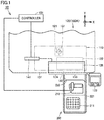
- Fig. 1 is a top view showing a machining system according to the first embodiment of the present invention.
- a machining system 10 according to the present embodiment includes a machine tool 100 and a conveyance unit 200.
- Machine tool 100 machines a workpiece.
- Machine tool 100 is a numerically control (NC) machine tool performing various operations for workpiece machining that are automated by numerical control by a computer.
- Conveyance unit 200 is provided adjacent to machine tool 100.
- Conveyance unit 200 is a device for conveying a workpiece, which is an object to be conveyed, with respect to (into and out of) machine tool 100.
- a vertical machining center 100A is provided as machine tool 100.
- Vertical machining center 100A includes a spindle 121, a table 122, a cover body 131, a door portion 136, an actuator 141, a controller 151, and an operation panel 123.
- Spindle 121 is provided to be movable inside a machining area 110 for a workpiece.
- Spindle 121 is provided to be movable in a Z-axis direction parallel to the vertical direction.
- Spindle 121 is provided to be rotatable by motor driving around a central axis 101 parallel to the Z-axis.
- Spindle 121 is equipped with a clamp mechanism for detachably holding various tools.
- Table 122 is provided to be movable inside machining area 110.
- Table 122 is provided to be movable in a plane (an X-Y plane) including: an X-axis direction (the right-left direction) parallel to the horizontal direction; and a Y-axis direction (the front-rear direction) parallel to the horizontal direction and orthogonal to the X-axis direction.
- a workpiece mounting jig (not shown) for detachably holding a workpiece is provided.
- Cover body 131 which is also called a splash guard, forms an outer appearance of vertical machining center 100A and defines machining area 110.
- Cover body 131 has an opening 132. Opening 132 is provided to open from the front surface to the upper surface of cover body 131 and is in communication with machining area 110.
- Door portion 136 is provided in opening 132. Door portion 136 is provided to be slidable in the horizontal direction. Door portion 136 is provided to be slidable in the X-axis direction. When door portion 136 performs the opening and closing operations, opening 132 is brought into an opened state and a closed state accordingly. When door portion 136 is in the closed state, door portion 136 defines machining area 110 together with cover body 131. Door portion 136 is equipped with a transparent window (not shown) through which an operator can see the interior of machining area 110.
- the operation of door portion 136 that is performed when the opening area of opening 132 increases is referred to as an "opening operation”.
- the operation of door portion 136 that slides to the left in Fig. 1 corresponds to the "opening operation”.
- the operation of door portion 136 that is performed when the opening area of opening 132 decreases is referred to as a "closing operation”.
- the operation of door portion 136 that slides to the right in Fig. 1 corresponds to the "closing operation”.
- Actuator 141 is provided in cover body 131. Actuator 141 is connected to door portion 136. Actuator 141 is driven to cause door portion 136 to perform the opening and closing operations.
- the type of actuator 141 is not particularly limited, but may be a linear motion-type servo motor by way of example. Actuator 141 can stop door portion 136 at an arbitrary position.
- Controller 151 controls vertical machining center 100A. Controller 151 is installed in vertical machining center 100A and serves as a control panel through which various operations in vertical machining center 100A are controlled. Controller 151 controls actuator 141. Controller 151 further controls a robot arm 212 in conveyance unit 200.
- Operation panel 123 is configured in such a manner that various devices required to operate and adjust vertical machining center 100A are collectively arranged thereon. Operation panel 123 is provided on the front surface of cover body 131. Operation panel 123 is provided adjacent to opening 132. Operation panel 123 corresponds to an input unit through which a control program for actuator 141 is input.
- Fig. 2 is a perspective view showing a conveyance unit in Fig. 1 .
- conveyance unit 200 includes a robot arm 212, a workpiece mounting portion 211, and a guard body 221.
- Robot arm 212 is provided adjacent to vertical machining center 100A in the Y-axis direction.
- Robot arm 212 is provided to face opening 132 (door portion 136 in the closed state).
- Robot arm 212 operates through opening 132 to convey a workpiece between machining area 110 and an external area outside this machining area 110.
- Robot arm 212 has a workpiece gripping portion (not shown) capable of gripping a workpiece.
- Robot arm 212 is a multi-joint robot having a plurality of axes (typically, six axes) that can be controlled independently of each other.
- Workpiece mounting portion 211 is provided adjacent to robot arm 212. Workpiece mounting portion 211 is provided in an operation region of robot arm 212. Workpiece mounting portion 211 is provided on the opposite side of opening 132 (door portion 136 in the closed state) with robot arm 212 interposed therebetween. Opening 132 (door portion 136 in the closed state), robot arm 212, and workpiece mounting portion 211 are arranged in this order in the Y-axis direction.
- Workpiece mounting portion 211 is configured such that a plurality of workpieces can be mounted thereon.
- workpiece mounting portion 211 is formed of a plate member that is provided with a plurality of holes into which the respective workpieces can be inserted.
- Guard body 221 is provided to surround robot arm 212 in the external area. Guard body 221 is provided to further surround workpiece mounting portion 211. Guard body 221 is provided to isolate the operation region of robot arm 212 from the operator in the external area. Guard body 221 is formed of a fence that surrounds robot arm 212 and workpiece mounting portion 211 from both sides in the X-axis direction and from one side in the Y-axis direction. Opening 222 of guard body 221 that is opened on the other side in the Y-axis direction faces opening 132 of cover body 131.
- Opening 132 has a facing region 133 and a non-facing region 134. Facing region 133 faces guard body 221. Facing region 133 faces opening 222 of guard body 221 in the Y-axis direction. The space inside guard body 221 in which robot arm 212 and workpiece mounting portion 211 are disposed is in communication with machining area 110 through facing region 133 of opening 132.
- Non-facing region 134 does not face guard body 221.
- Non-facing region 134 is provided adjacent to facing region 133 in the X-axis direction.
- the space outside guard body 221 in the external area is in communication with machining area 110 through non-facing region 134 of opening 132.
- Fig. 3 is a top view showing the machining system in which the door portion is positioned at the second position.
- Fig. 4 is a top view showing the machining system in which the door portion is positioned at the third position.
- door portion 136 is driven by actuator 141 to perform the opening and closing operations between: the first position at which opening 132 is closed as shown in Fig. 1 ; and the second position at which opening 132 is opened as shown in Fig. 3 .
- door portion 136 When door portion 136 is positioned at the first position, the opening area of opening 132 is zero. Opening 132 is closed by door portion 136, thereby blocking machining area 110 from the external area. When the workpiece is machined in machining area 110, door portion 136 is positioned at the first position. The first position is located at one slide end of door portion 136 in the X-axis direction.
- opening area of opening 132 is Sa.
- Opening area Sa of opening 132 is the maximum value of the opening area of door portion 136 that changes in accordance with the opening and closing operations.
- opening 132 is in a fully opened state.
- the second position is located at the other slide end of door portion 136 in the X-axis direction.
- controller 151 controls actuator 141 such that door portion 136 is positioned at the third position when robot arm 212 conveys a workpiece.
- opening area of opening 132 is Sb. Opening area Sb of opening 132 opened when door portion 136 is positioned at the third position is smaller than opening area Sa of opening 132 opened when door portion 136 is positioned at the second position (Sb ⁇ Sa).
- opening 132 When door portion 136 is positioned at the third position, opening 132 is in a half-opened state. When door portion 136 is positioned at the third position, opening 132 is set to have a minimum opening area (opening degree) in which robot arm 212 can perform the operation to convey a workpiece. Door portion 136 positioned at the third position is located between, in the X-axis direction, door portion 136 positioned at the first position shown in Fig. 1 and door portion 136 positioned at the second position shown in Fig. 3 .
- door portion 136 positioned at the first position closes facing region 133 and non-facing region 134 of opening 132.
- door portion 136 positioned at the second position opens facing region 133 and non-facing region 134 of opening 132.
- door portion 136 positioned at the third position opens facing region 133 and closes non-facing region 134.
- Fig. 5 is a flowchart showing an example of an operation of the machining system involved in workpiece machining. The operation of machining system 10 described below is performed based on the control program that is input in advance into controller 151 by an operator through operation panel 123, unless otherwise specified.
- door portion 136 is positioned at the first position as an initial state. Thereby, opening 132 is brought into a closed state.
- controller 151 first controls actuator 141 such that door portion 136 performs an opening operation so as to be positioned at the third position (S101). Thereby, opening 132 is brought into a half-opened state.
- controller 151 controls robot arm 212 to convey the workpiece into machining area 110 (S102).
- robot arm 212 grips an un-machined workpiece mounted on workpiece mounting portion 211.
- Robot arm 212 moves through opening 132 into machining area 110.
- robot arm 212 mounts the workpiece on a workpiece fixing jig (not shown) on table 122.
- Robot arm 212 retracts from machining area 110 through opening 132.
- controller 151 then controls actuator 141 such that door portion 136 performs the closing operation so as to be positioned at the first position (SI03). Thereby, opening 132 is brought into a closed state. Then, controller 151 controls vertical machining center 100A to perform workpiece machining (rough machining) (S104).
- controller 151 controls actuator 141 such that door portion 136 performs an opening operation so as to be positioned at the second position (S105). Thereby, opening 132 is brought into a fully opened state. In this step, controller 151 may perform the opening operation of door portion 136 based on the command input by the operator through operation panel 123.
- the operator measures the workpiece (S106).
- the operator accesses the inside of machining area 110 through opening 132 that opens in non-facing region 134, to thereby measure the workpiece.
- the operator may correct the parameters for the subsequent finish machining of the workpiece based on the result of measuring the workpiece subjected to rough machining.
- controller 151 controls actuator 141 such that door portion 136 performs the closing operation so as to be positioned at the first position (SI07). Thereby, opening 132 is brought into a closed state. In this step, controller 151 may cause door portion 136 to perform the closing operation based on the command input by the operator through operation panel 123.
- controller 151 controls vertical machining center 100A to perform workpiece machining (finish machining) (S108).
- controller 151 controls actuator 141 such that door portion 136 performs an opening operation so as to be positioned at the third position (S109). Thereby, opening 132 is brought into a half-opened state.
- controller 151 controls robot arm 212 to convey the workpiece out of machining area 110 (S110).
- robot arm 212 moves through opening 132 into machining area 110.
- Robot arm 212 grips the machined workpiece mounted on the workpiece fixing jig (not shown) on table 122.
- Robot arm 212 retracts from machining area 110 through opening 132.
- Robot arm 212 places the workpiece on workpiece mounting portion 211.
- door portion 136 when robot arm 212 conveys the workpiece (SI02, S110), door portion 136 is positioned at the third position at which opening 132 has opening area Sb that is smaller than opening area Sa of opening 132 opened when door portion 136 is positioned at the second position.
- door portion 136 is positioned such that opening 132 is opened at the minimum opening degree required for robot arm 212 to convey the workpiece.
- opening 132 is opened at the minimum opening degree required for robot arm 212 to convey the workpiece.
- door portion 136 positioned at the third position shown in Fig. 4 opens facing region 133 of opening 132 and closes non-facing region 134 of opening 132.
- Such a configuration allows robot arm 212 to convey the workpiece through facing region 133 of opening 132.
- robot arm 212 is surrounded by guard body 221 and non-facing region 134 of opening 132 is closed by door portion 136. Thereby, the operator can be prevented from entering the operation region of robot arm 212.
- Fig. 6 is a top view showing the machining system in which the door portion is positioned at the fourth position.
- controller 151 may control actuator 141 such that door portion 136 is positioned at the fourth position when robot arm 212 does not convey the workpiece and when workpiece machining in machining area 110 is stopped.
- opening area of opening 132 is Sc. Opening area Sc of opening 132 opened when door portion 136 is positioned at the fourth position is smaller than opening area Sa of opening 132 opened when door portion 136 is positioned at the second position (Sc ⁇ Sa).
- Door portion 136 positioned at the fourth position is located between, in the X-axis direction, door portion 136 positioned at the third position shown in Fig. 4 and door portion 136 positioned at the second position shown in Fig. 3 .
- Door portion 136 positioned at the fourth position opens facing region 133 and a part of non-facing region 134 and closes the remaining part of non-facing region 134.
- the operator can perform various operations through opening 132 that is opened in a part of non-facing region 134. For example, the operator may clean the interior of machining area 110. The operator may perform the measurement of the workpiece as described in S106 in Fig. 5 in the state where door portion 136 is positioned at the fourth position.
- door portion 136 is positioned at the fourth position at which opening 132 has an opening area that is smaller than the opening area of opening 132 opened when door portion 136 is positioned at the second position. Accordingly, the energy consumed by actuator 141 during the opening and closing operations of door portion 136 can be suppressed. In addition, when the interior of machining area 110 is cleaned, the effect of suppressing scattering of a coolant, chippings and the like in the external area due to air blowing during cleaning is also achieved.
- machining system 10 includes: a cover body 131 having an opening 132 and defining a machining area 110 of a workpiece; a door portion 136 provided in opening 132; an actuator 141 that operates door portion 136 between a first position at which opening 132 is closed and a second position at which opening 132 is opened; a controller 151 that controls actuator 141; and a robot arm 212 as a conveyance device that operates through opening 132 to convey the workpiece as an object to be conveyed between machining area 110 and an external area outside machining area 110.
- Controller 151 controls actuator 141 such that door portion 136 is positioned at a third position when robot arm 212 conveys the workpiece.
- An opening area Sb of opening132 opened when door portion 136 is positioned at the third position is smaller than an opening area Sa of opening 132 opened when door portion 136 is positioned at the second position.
- Machining system 10 according to the first embodiment of the present invention that is configured as described above can suppress the energy consumed by actuator 141 to cause door portion 136 to perform the opening and closing operations before and after conveyance of the workpiece. Thereby, the energy saving performance of machining system 10 can be improved.
- the present embodiment has been described above with regard to the case where the conveyance device is robot arm 212 as a multi-joint robot, but the present invention is not limited thereto.
- the conveyance device of the present invention may be, for example, a linear motion-type workpiece conveyance device that conveys a workpiece in a linear direction.
- the object to be conveyed that is conveyed by the conveyance device is not limited to a workpiece but may be a tool, for example.
- Fig. 7 is a top view showing a machining system according to the second embodiment of the present invention.
- the machining system according to the present embodiment has basically the same structure as that of the machining system according to the first embodiment. Thus, the description of the same structure will not be hereinafter repeated.
- a machining system 20 in the present embodiment is equipped with a lathe 100B as machine tool 100.
- Lathe 100B includes a spindle 161 (a first spindle 161P, a second spindle 161Q), a tool rest 166, a cover body 131, a door portion 136 (a first door portion 136P, a second door portion 136Q), an actuator 141 (a first actuator 141P, a second actuator 141Q), a controller 151, and an operation panel 123.
- First spindle 161P and second spindle 161Q are disposed to face each other in a Z-axis direction (the right-left direction) parallel to the horizontal direction.
- First spindle 161P is disposed to be rotatable about a central axis 106 parallel to the Z-axis.
- Second spindle 161Q is disposed to be rotatable about a central axis 107 that extends in parallel to the Z-axis along the line extending from central axis 106.
- First spindle 161P and second spindle 161Q are equipped with a chuck mechanism for detachably holding a workpiece.
- Tool rest 166 is configured such that a plurality of tools can be mounted thereon.
- Tool rest 166 is a so-called turret type of rest and equipped with a plurality of tools radially arranged for swivel indexing. More specifically, tool rest 166 is disposed to be swivelable around a central axis 108 parallel to the Z-axis. Further, tool holders for holding respective tools are attached at positions around central axis 108 to be spaced apart from each other in the circumferential direction of central axis 108. As tool rest 166 swivels around central axis 108, the tools held by the respective tool holders move in the circumferential direction, and thus, a tool used for machining is indexed.
- Second spindle 161Q is disposed to be movable in the Z-axis direction.
- Tool rest 166 is disposed to be movable in the Z-axis direction and in the X-axis direction that is orthogonal to the Z-axis and inclined with respect to the vertical direction.
- Door portion 136 is a type of double doors including a first door portion 136P and a second door portion 136Q that closes opening 132 together with first door portion 136P.
- First door portion 136P and second door portion 136Q are disposed side by side in the Z-axis direction.
- First door portion 136P and second door portion 136Q are disposed to be slidable in the Z-axis direction.
- Actuator 141 includes a first actuator 141P and a second actuator 141Q.
- First actuator 141P causes first door portion 136P to perform the opening and closing operations.
- Second actuator 141Q causes second door portion 136Q to perform the opening and closing operations.
- first door portion 136P and second door portion 136Q are driven by first actuator 141P and second actuator 141Q, respectively, to be capable of performing the opening and closing operations independently from each other.
- Fig. 8 is a top view showing the machining system in which the door portion is positioned at the second position.
- door portion 136 (first door portion 136P, second door portion 136Q) is driven by actuator 141 (first actuator 141P, second actuator 141Q) to perform the opening and closing operations between the first position at which opening 132 is closed as shown in Fig. 7 and the second position at which opening 132 is opened as shown in Fig. 8 .
- the opening area of opening 132 is zero.
- the opening area of opening 132 is Sa.
- Opening 132 has a facing region 133 and a non-facing region 134. Facing region 133 faces guard body 221. Facing region 133 is closed by first door portion 136P positioned at the first position. Non-facing region 134 does not face guard body 221. Non-facing region 134 is closed by second door portion 136Q positioned at the first position.
- Fig. 9 is a top view showing the machining system in which the door portion is positioned at the third position.
- controller 151 controls actuator 141 (first actuator 141P, second actuator 141Q) such that door portion 136 (first door portion 136P, second door portion 136Q) is positioned at the third position when robot arm 212 conveys a workpiece.
- Opening area Sb of opening 132 opened when door portion 136 (first door portion 136P, second door portion 136Q) is positioned at the third position is smaller than opening area Sa of opening 132 opened when door portion 136 (first door portion 136P, second door portion 136Q) is positioned at the second position (Sb ⁇ Sa).
- Controller 151 controls first actuator 141P and second actuator 141Q such that only first door portion 136P among first door portion 136P and second door portion 136Q performs the opening operation when robot arm 212 conveys a workpiece.
- first door portion 136P among first door portion 136P and second door portion 136Q performs the opening operation, so that the energy consumed by actuator 141 to cause door portion 136 to perform the opening and closing operations can be suppressed. Thereby, the energy saving performance of machining system 20 can be improved.
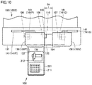
- Fig. 10 is a top view showing the machining system in which the door portion is positioned at the fourth position.
- controller 151 may control actuator 141 (first actuator 141P, second actuator 141Q) such that door portion 136 (first door portion 136P, second door portion 136Q) is positioned at the fourth position when robot arm 212 does not convey a workpiece and when workpiece machining in machining area 110 is stopped.
- Opening area Sc of opening 132 opened when door portion 136 (first door portion 136P, second door portion 136Q) is positioned at the fourth position is smaller than opening area Sa of opening 132 opened when door portion 136 (first door portion 136P, second door portion 136Q) is positioned at the second position (Sc ⁇ Sa). Opening area Sc of opening 132 opened when door portion 136 (first door portion 136P, second door portion 136Q) is positioned at the fourth position is further smaller than opening area Sb of opening 132 opened when door portion 136 (first door portion 136P, second door portion 136Q) is positioned at the third position (Sc ⁇ Sb).
- First door portion 136P positioned at the fourth position is positioned at the same position as that of first door portion 136P positioned at the first position. First door portion 136P positioned at the fourth position closes facing region 133. Second door portion 136Q positioned at the fourth position is positioned between, in the X-axis direction, second door portion 136Q positioned at the first position and second door portion 136Q positioned at the second position. Second door portion 136Q positioned at the fourth position opens a part of non-facing region 134 and closes the remaining part of non-facing region 134.
- door portion 136 is positioned at the fourth position at which opening 132 has an opening area that is smaller than the opening areas of opening 132 opened when door portion 136 is positioned at the second position and the third position. Therefore, the energy consumed by actuator 141 to cause door portion 136 to perform the opening and closing operations can be suppressed.
- the machining apparatus to which the machining system of the present invention is applied is not limited to a vertical machining center and a lathe.
- the present invention may also be applicable to: a horizontal machining center; a composite machining apparatus having a turning function using a fixed tool and a milling function using a rotating tool; a machining apparatus capable of performing subtractive manufacturing and additive manufacturing; or the like.
- a machining system includes: a cover body having an opening and defining a machining area of a workpiece; a door portion provided in the opening; an actuator that operates the door portion between a first position at which the opening is closed and a second position at which the opening is opened; a controller that controls the actuator; and a conveyance device that operates through the opening to convey an object to be conveyed between the machining area and an external area outside the machining area.
- the controller controls the actuator such that the door portion is positioned at a third position when the conveyance device conveys the object to be conveyed.
- An opening area of the opening opened when the door portion is positioned at the third position is smaller than an opening area of the opening opened when the door portion is positioned at the second position.
- the door portion when the conveyance device conveys the object to be conveyed, the door portion is positioned at the third position at which the opening has an opening area that is smaller than the opening area of the opening opened when the door portion is positioned at the second position.
- the energy consumed by the actuator to cause the door portion to perform the opening and closing operations can be suppressed.
- the energy saving performance can be improved.
- the machining system further includes a guard body that surrounds the conveyance device in the external area.
- the opening includes a facing region that faces the guard body and a non-facing region that does not face the guard body.
- the door portion positioned at the third position opens the facing region and closes the non-facing region.
- the door portion positioned at the second position opens the facing region and the non-facing region.
- the conveyance device when the door portion is positioned at the third position, the conveyance device can convey the object to be conveyed through the facing region of the opening.
- the conveyance device is surrounded by the guard body and the non-facing region of the opening is closed by the door portion, so that the operator can be prevented from entering the operation region of the conveyance device.
- the controller controls the actuator such that the door portion is positioned at a fourth position when the conveyance device does not convey the object to be conveyed and when workpiece machining in the machining area is stopped.
- An opening area of the opening opened when the door portion is positioned at the fourth position is smaller than an opening area of the opening opened when the door portion is positioned at the second position.
- the operator when the conveyance device does not convey the object to be conveyed and when workpiece machining in the machining area is stopped, the operator can perform various operations in the machining area through the opening.
- the opening area of the opening opened when the door portion is positioned at the fourth position is smaller than the opening area of the opening opened when the door portion is positioned at the second position.
- the opening area of the opening opened when the door portion is positioned at the fourth position is further smaller than the opening area of the opening opened when the door portion is positioned at the third position.
- the energy consumed by the actuator to cause the door portion to perform the opening and closing operations can be further suppressed.
- the machining system further includes an input unit through which a control program for the actuator is input into the controller.
- the controller controls the actuator based on the control program input through the input unit.
- the door portion can be caused to perform the opening and closing operations based on the control program input in advance.
- the door portion includes a first door portion and a second door portion that closes the opening together with the first door portion.
- the controller controls the actuator such that one of the first door portion and the second door portion performs the opening operation when the conveyance device conveys the object to be conveyed.
- the machining system configured as described above, only one of the doors configured as double doors is caused to perform the opening operation when the conveyance device conveys the object to be conveyed. Thereby, the energy saving performance can be improved.
- the present invention is applicable mainly to a machining system including a door portion that automatically performs opening and closing operations.
- 10, 20 machining system 100 machine tool, 100A vertical machining center, 100B lathe, 101, 106, 107, 108 central axis, 110 machining area, 121 spindle, 122 table, 123 control panel, 131 cover body, 132, 222 opening, 133 facing region, 134 non-facing region, 136 door portion, 136P first door portion, 136Q second door portion, 141 actuator, 141P first actuator, 141Q second actuator, 151 controller, 161 spindle, 161P first spindle, 161Q second spindle, 166 tool rest, 200 conveyance unit, 211 workpiece mounting portion, 212 robot arm, 221 guard body.
Landscapes
- Engineering & Computer Science (AREA)
- Mechanical Engineering (AREA)
- Human Computer Interaction (AREA)
- Manufacturing & Machinery (AREA)
- Physics & Mathematics (AREA)
- General Physics & Mathematics (AREA)
- Automation & Control Theory (AREA)
- Auxiliary Devices For Machine Tools (AREA)
Abstract
Description
- The present invention relates to a machining system.
- With regard to a conventional machining system, for example,
Japanese Patent Laying-Open No. 2014-205231 - The robot controller can control opening and closing of the door and also synchronously controls the robot and the door in accordance with the position and the posture of the robot and the position of the door. For example, the robot controller starts the operation of the robot to move into the machining apparatus before the door reaches an opened position, or starts the operation to close the door before the retraction operation of the robot completes.
- PTL 1:
Japanese Patent Laying-Open No. 2014-205231 - As disclosed in the above-mentioned
PTL 1, a machining system has been known that uses a robot to convey an object to be conveyed such as a workpiece into and out of a machining apparatus having a door that automatically performs opening and closing operations. Such a machining system requires driving of an actuator in order to automatically open and close the door, thereby resulting in poor energy saving performance. - Thus, an object of the present invention is to solve the above-described problem and to provide a machining system that is improved in energy saving performance.
- A machining system according to the present invention includes: a cover body having an opening and defining a machining area of a workpiece; a door portion provided in the opening; an actuator that operates the door portion between a first position at which the opening is closed and a second position at which the opening is opened; a controller that controls the actuator; and a conveyance device that operates through the opening to convey an object to be conveyed between the machining area and an external area outside the machining area. The controller controls the actuator such that the door portion is positioned at a third position when the conveyance device conveys the object to be conveyed. An opening area of the opening opened when the door portion is positioned at the third position is smaller than an opening area of the opening opened when the door portion is positioned at the second position.
- According to the present invention, a machining system that is improved in energy saving performance can be provided.
-
-
Fig. 1 is a top view showing a machining system according to the first embodiment of the present invention. -
Fig. 2 is a perspective view showing a conveyance unit inFig. 1 . -
Fig. 3 is a top view showing the machining system in which a door portion is positioned at a second position. -
Fig. 4 is a top view showing the machining system in which the door portion is positioned at a third position. -
Fig. 5 is a flowchart showing an example of an operation of the machining system involved in workpiece machining. -
Fig. 6 is a top view showing the machining system in which the door portion is positioned at a fourth position. -
Fig. 7 is a top view showing a machining system according to the second embodiment of the present invention. -
Fig. 8 is a top view showing the machining system in which a door portion is positioned at a second position. -
Fig. 9 is a top view showing the machining system in which the door portion is positioned at a third position. -
Fig. 10 is a top view showing the machining system in which the door portion is positioned at a fourth position. - The embodiments of the present invention will be hereinafter described with reference to the accompanying drawings. In the accompanying drawings referred to below, the same or corresponding members will be denoted by the same reference characters.
-
Fig. 1 is a top view showing a machining system according to the first embodiment of the present invention. Referring toFig. 1 , amachining system 10 according to the present embodiment includes amachine tool 100 and aconveyance unit 200. -
Machine tool 100 machines a workpiece.Machine tool 100 is a numerically control (NC) machine tool performing various operations for workpiece machining that are automated by numerical control by a computer.Conveyance unit 200 is provided adjacent tomachine tool 100.Conveyance unit 200 is a device for conveying a workpiece, which is an object to be conveyed, with respect to (into and out of)machine tool 100. - In the present embodiment, a
vertical machining center 100A is provided asmachine tool 100.Vertical machining center 100A includes aspindle 121, a table 122, acover body 131, adoor portion 136, anactuator 141, acontroller 151, and anoperation panel 123. - Spindle 121 is provided to be movable inside a
machining area 110 for a workpiece.Spindle 121 is provided to be movable in a Z-axis direction parallel to the vertical direction. Spindle 121 is provided to be rotatable by motor driving around acentral axis 101 parallel to the Z-axis. Spindle 121 is equipped with a clamp mechanism for detachably holding various tools. - Table 122 is provided to be movable inside
machining area 110. Table 122 is provided to be movable in a plane (an X-Y plane) including: an X-axis direction (the right-left direction) parallel to the horizontal direction; and a Y-axis direction (the front-rear direction) parallel to the horizontal direction and orthogonal to the X-axis direction. On table 122, a workpiece mounting jig (not shown) for detachably holding a workpiece is provided. -
Cover body 131, which is also called a splash guard, forms an outer appearance ofvertical machining center 100A and definesmachining area 110.Cover body 131 has anopening 132.Opening 132 is provided to open from the front surface to the upper surface ofcover body 131 and is in communication withmachining area 110. -
Door portion 136 is provided inopening 132.Door portion 136 is provided to be slidable in the horizontal direction.Door portion 136 is provided to be slidable in the X-axis direction. Whendoor portion 136 performs the opening and closing operations, opening 132 is brought into an opened state and a closed state accordingly. Whendoor portion 136 is in the closed state,door portion 136 definesmachining area 110 together withcover body 131.Door portion 136 is equipped with a transparent window (not shown) through which an operator can see the interior ofmachining area 110. - The operation of
door portion 136 that is performed when the opening area of opening 132 increases is referred to as an "opening operation". The operation ofdoor portion 136 that slides to the left inFig. 1 corresponds to the "opening operation". The operation ofdoor portion 136 that is performed when the opening area of opening 132 decreases is referred to as a "closing operation". The operation ofdoor portion 136 that slides to the right inFig. 1 corresponds to the "closing operation". -
Actuator 141 is provided incover body 131.Actuator 141 is connected todoor portion 136.Actuator 141 is driven to causedoor portion 136 to perform the opening and closing operations. The type ofactuator 141 is not particularly limited, but may be a linear motion-type servo motor by way of example.Actuator 141 can stopdoor portion 136 at an arbitrary position. -
Controller 151 controlsvertical machining center 100A.Controller 151 is installed invertical machining center 100A and serves as a control panel through which various operations invertical machining center 100A are controlled.Controller 151 controls actuator 141.Controller 151 further controls arobot arm 212 inconveyance unit 200. -
Operation panel 123 is configured in such a manner that various devices required to operate and adjustvertical machining center 100A are collectively arranged thereon.Operation panel 123 is provided on the front surface ofcover body 131.Operation panel 123 is provided adjacent toopening 132.Operation panel 123 corresponds to an input unit through which a control program foractuator 141 is input. -
Fig. 2 is a perspective view showing a conveyance unit inFig. 1 . Referring toFigs. 1 and2 ,conveyance unit 200 includes arobot arm 212, aworkpiece mounting portion 211, and aguard body 221. -
Robot arm 212 is provided adjacent tovertical machining center 100A in the Y-axis direction.Robot arm 212 is provided to face opening 132 (door portion 136 in the closed state).Robot arm 212 operates throughopening 132 to convey a workpiece betweenmachining area 110 and an external area outside thismachining area 110.Robot arm 212 has a workpiece gripping portion (not shown) capable of gripping a workpiece.Robot arm 212 is a multi-joint robot having a plurality of axes (typically, six axes) that can be controlled independently of each other. -
Workpiece mounting portion 211 is provided adjacent torobot arm 212.Workpiece mounting portion 211 is provided in an operation region ofrobot arm 212.Workpiece mounting portion 211 is provided on the opposite side of opening 132 (door portion 136 in the closed state) withrobot arm 212 interposed therebetween. Opening 132 (door portion 136 in the closed state),robot arm 212, andworkpiece mounting portion 211 are arranged in this order in the Y-axis direction. -
Workpiece mounting portion 211 is configured such that a plurality of workpieces can be mounted thereon. By way of example,workpiece mounting portion 211 is formed of a plate member that is provided with a plurality of holes into which the respective workpieces can be inserted. -
Guard body 221 is provided to surroundrobot arm 212 in the external area.Guard body 221 is provided to further surroundworkpiece mounting portion 211.Guard body 221 is provided to isolate the operation region ofrobot arm 212 from the operator in the external area.Guard body 221 is formed of a fence that surroundsrobot arm 212 andworkpiece mounting portion 211 from both sides in the X-axis direction and from one side in the Y-axis direction. Opening 222 ofguard body 221 that is opened on the other side in the Y-axis direction faces opening 132 ofcover body 131. -
Opening 132 has a facingregion 133 and anon-facing region 134. Facingregion 133 facesguard body 221. Facingregion 133 faces opening 222 ofguard body 221 in the Y-axis direction. The space insideguard body 221 in whichrobot arm 212 andworkpiece mounting portion 211 are disposed is in communication withmachining area 110 through facingregion 133 ofopening 132. -
Non-facing region 134 does not faceguard body 221.Non-facing region 134 is provided adjacent to facingregion 133 in the X-axis direction. The space outsideguard body 221 in the external area is in communication withmachining area 110 throughnon-facing region 134 ofopening 132. -
Fig. 3 is a top view showing the machining system in which the door portion is positioned at the second position.Fig. 4 is a top view showing the machining system in which the door portion is positioned at the third position. - Referring to
Figs. 1 and3 ,door portion 136 is driven byactuator 141 to perform the opening and closing operations between: the first position at whichopening 132 is closed as shown inFig. 1 ; and the second position at whichopening 132 is opened as shown inFig. 3 . - When
door portion 136 is positioned at the first position, the opening area ofopening 132 is zero.Opening 132 is closed bydoor portion 136, thereby blockingmachining area 110 from the external area. When the workpiece is machined inmachining area 110,door portion 136 is positioned at the first position. The first position is located at one slide end ofdoor portion 136 in the X-axis direction. - When
door portion 136 is positioned at the second position, the opening area ofopening 132 is Sa. Opening area Sa of opening 132 is the maximum value of the opening area ofdoor portion 136 that changes in accordance with the opening and closing operations. Whendoor portion 136 is positioned at the second position, opening 132 is in a fully opened state. The second position is located at the other slide end ofdoor portion 136 in the X-axis direction. - Referring to
Fig. 4 , controller 151 (seeFig. 1 ) controlsactuator 141 such thatdoor portion 136 is positioned at the third position whenrobot arm 212 conveys a workpiece. - Referring to
Figs. 1 ,3 , and4 , whendoor portion 136 is positioned at the third position, the opening area ofopening 132 is Sb. Opening area Sb of opening 132 opened whendoor portion 136 is positioned at the third position is smaller than opening area Sa of opening 132 opened whendoor portion 136 is positioned at the second position (Sb < Sa). - When
door portion 136 is positioned at the third position, opening 132 is in a half-opened state. Whendoor portion 136 is positioned at the third position, opening 132 is set to have a minimum opening area (opening degree) in whichrobot arm 212 can perform the operation to convey a workpiece.Door portion 136 positioned at the third position is located between, in the X-axis direction,door portion 136 positioned at the first position shown inFig. 1 anddoor portion 136 positioned at the second position shown inFig. 3 . - As shown in
Fig. 1 ,door portion 136 positioned at the first position closes facingregion 133 andnon-facing region 134 ofopening 132. As shown inFig. 3 ,door portion 136 positioned at the second position opens facingregion 133 andnon-facing region 134 ofopening 132. As shown inFig. 4 ,door portion 136 positioned at the third position opens facingregion 133 and closesnon-facing region 134. -
Fig. 5 is a flowchart showing an example of an operation of the machining system involved in workpiece machining. The operation ofmachining system 10 described below is performed based on the control program that is input in advance intocontroller 151 by an operator throughoperation panel 123, unless otherwise specified. - Referring to
Figs. 1 and5 ,door portion 136 is positioned at the first position as an initial state. Thereby, opening 132 is brought into a closed state. - Referring to
Figs. 4 and5 ,controller 151 first controls actuator 141 such thatdoor portion 136 performs an opening operation so as to be positioned at the third position (S101). Thereby, opening 132 is brought into a half-opened state. - Then,
controller 151controls robot arm 212 to convey the workpiece into machining area 110 (S102). In this step,robot arm 212 grips an un-machined workpiece mounted onworkpiece mounting portion 211.Robot arm 212 moves throughopening 132 intomachining area 110. Further,robot arm 212 mounts the workpiece on a workpiece fixing jig (not shown) on table 122.Robot arm 212 retracts from machiningarea 110 throughopening 132. - Referring to
Figs. 1 and5 ,controller 151 then controlsactuator 141 such thatdoor portion 136 performs the closing operation so as to be positioned at the first position (SI03). Thereby, opening 132 is brought into a closed state. Then,controller 151 controlsvertical machining center 100A to perform workpiece machining (rough machining) (S104). - Referring to
Figs. 3 and5 , after completion of workpiece machining (rough machining),controller 151 controls actuator 141 such thatdoor portion 136 performs an opening operation so as to be positioned at the second position (S105). Thereby, opening 132 is brought into a fully opened state. In this step,controller 151 may perform the opening operation ofdoor portion 136 based on the command input by the operator throughoperation panel 123. - Then, the operator measures the workpiece (S106). The operator accesses the inside of
machining area 110 throughopening 132 that opens innon-facing region 134, to thereby measure the workpiece. The operator may correct the parameters for the subsequent finish machining of the workpiece based on the result of measuring the workpiece subjected to rough machining. - Referring to
Figs. 1 and5 , after completion of the measurement of the workpiece,controller 151 controls actuator 141 such thatdoor portion 136 performs the closing operation so as to be positioned at the first position (SI07). Thereby, opening 132 is brought into a closed state. In this step,controller 151 may causedoor portion 136 to perform the closing operation based on the command input by the operator throughoperation panel 123. - Then,
controller 151 controlsvertical machining center 100A to perform workpiece machining (finish machining) (S108). - Referring to
Figs. 4 and5 , after completion of workpiece machining (finish machining),controller 151 controls actuator 141 such thatdoor portion 136 performs an opening operation so as to be positioned at the third position (S109). Thereby, opening 132 is brought into a half-opened state. - Then,
controller 151controls robot arm 212 to convey the workpiece out of machining area 110 (S110). In this step,robot arm 212 moves throughopening 132 intomachining area 110.Robot arm 212 grips the machined workpiece mounted on the workpiece fixing jig (not shown) on table 122.Robot arm 212 retracts from machiningarea 110 throughopening 132.Robot arm 212 places the workpiece onworkpiece mounting portion 211. - As described above, in the present embodiment, when
robot arm 212 conveys the workpiece (SI02, S110),door portion 136 is positioned at the third position at whichopening 132 has opening area Sb that is smaller than opening area Sa of opening 132 opened whendoor portion 136 is positioned at the second position. This suppresses the energy consumed byactuator 141 whendoor portion 136 performs the opening and closing operations before and after conveyance of the workpiece. Accordingly, the energy saving performance ofmachining system 10 can be improved. - In addition,
door portion 136 is positioned such thatopening 132 is opened at the minimum opening degree required forrobot arm 212 to convey the workpiece. Thus, the time required for the opening and closing operations ofdoor portion 136 before and after conveyance of the workpiece can be shortened. Thereby, the effect of shortening the cycle time of workpiece machining inmachining system 10 is also achieved. - Further,
door portion 136 positioned at the third position shown inFig. 4 opens facingregion 133 ofopening 132 and closesnon-facing region 134 ofopening 132. Such a configuration allowsrobot arm 212 to convey the workpiece through facingregion 133 ofopening 132. Further,robot arm 212 is surrounded byguard body 221 andnon-facing region 134 ofopening 132 is closed bydoor portion 136. Thereby, the operator can be prevented from entering the operation region ofrobot arm 212. -
Fig. 6 is a top view showing the machining system in which the door portion is positioned at the fourth position. Referring toFig. 6 , controller 151 (seeFig. 1 ) may controlactuator 141 such thatdoor portion 136 is positioned at the fourth position whenrobot arm 212 does not convey the workpiece and when workpiece machining inmachining area 110 is stopped. - When
door portion 136 is positioned at the fourth position, the opening area ofopening 132 is Sc. Opening area Sc of opening 132 opened whendoor portion 136 is positioned at the fourth position is smaller than opening area Sa of opening 132 opened whendoor portion 136 is positioned at the second position (Sc < Sa). -
Door portion 136 positioned at the fourth position is located between, in the X-axis direction,door portion 136 positioned at the third position shown inFig. 4 anddoor portion 136 positioned at the second position shown inFig. 3 .Door portion 136 positioned at the fourth position opens facingregion 133 and a part ofnon-facing region 134 and closes the remaining part ofnon-facing region 134. - In such a configuration, when
robot arm 212 does not convey the workpiece and when the workpiece machining inmachining area 110 is stopped, the operator can perform various operations through opening 132 that is opened in a part ofnon-facing region 134. For example, the operator may clean the interior ofmachining area 110. The operator may perform the measurement of the workpiece as described in S106 inFig. 5 in the state wheredoor portion 136 is positioned at the fourth position. - In this case,
door portion 136 is positioned at the fourth position at whichopening 132 has an opening area that is smaller than the opening area of opening 132 opened whendoor portion 136 is positioned at the second position. Accordingly, the energy consumed byactuator 141 during the opening and closing operations ofdoor portion 136 can be suppressed. In addition, when the interior ofmachining area 110 is cleaned, the effect of suppressing scattering of a coolant, chippings and the like in the external area due to air blowing during cleaning is also achieved. - The following summarizes the above-described structure of
machining system 10 according to the first embodiment of the present invention. Specifically,machining system 10 according to the present embodiment includes: acover body 131 having anopening 132 and defining amachining area 110 of a workpiece; adoor portion 136 provided inopening 132; anactuator 141 that operatesdoor portion 136 between a first position at whichopening 132 is closed and a second position at whichopening 132 is opened; acontroller 151 that controlsactuator 141; and arobot arm 212 as a conveyance device that operates throughopening 132 to convey the workpiece as an object to be conveyed betweenmachining area 110 and an external area outsidemachining area 110.Controller 151 controls actuator 141 such thatdoor portion 136 is positioned at a third position whenrobot arm 212 conveys the workpiece. An opening area Sb of opening132 opened whendoor portion 136 is positioned at the third position is smaller than an opening area Sa of opening 132 opened whendoor portion 136 is positioned at the second position. -
Machining system 10 according to the first embodiment of the present invention that is configured as described above can suppress the energy consumed byactuator 141 to causedoor portion 136 to perform the opening and closing operations before and after conveyance of the workpiece. Thereby, the energy saving performance ofmachining system 10 can be improved. - The present embodiment has been described above with regard to the case where the conveyance device is
robot arm 212 as a multi-joint robot, but the present invention is not limited thereto. The conveyance device of the present invention may be, for example, a linear motion-type workpiece conveyance device that conveys a workpiece in a linear direction. Furthermore, the object to be conveyed that is conveyed by the conveyance device is not limited to a workpiece but may be a tool, for example. -
Fig. 7 is a top view showing a machining system according to the second embodiment of the present invention. The machining system according to the present embodiment has basically the same structure as that of the machining system according to the first embodiment. Thus, the description of the same structure will not be hereinafter repeated. - Referring to
Fig. 7 , amachining system 20 in the present embodiment is equipped with alathe 100B asmachine tool 100. -
Lathe 100B includes a spindle 161 (afirst spindle 161P, asecond spindle 161Q), atool rest 166, acover body 131, a door portion 136 (afirst door portion 136P, asecond door portion 136Q), an actuator 141 (afirst actuator 141P, asecond actuator 141Q), acontroller 151, and anoperation panel 123. -
First spindle 161P andsecond spindle 161Q are disposed to face each other in a Z-axis direction (the right-left direction) parallel to the horizontal direction.First spindle 161P is disposed to be rotatable about acentral axis 106 parallel to the Z-axis.Second spindle 161Q is disposed to be rotatable about acentral axis 107 that extends in parallel to the Z-axis along the line extending fromcentral axis 106.First spindle 161P andsecond spindle 161Q are equipped with a chuck mechanism for detachably holding a workpiece. -
Tool rest 166 is configured such that a plurality of tools can be mounted thereon.Tool rest 166 is a so-called turret type of rest and equipped with a plurality of tools radially arranged for swivel indexing. More specifically,tool rest 166 is disposed to be swivelable around acentral axis 108 parallel to the Z-axis. Further, tool holders for holding respective tools are attached at positions aroundcentral axis 108 to be spaced apart from each other in the circumferential direction ofcentral axis 108. Astool rest 166 swivels aroundcentral axis 108, the tools held by the respective tool holders move in the circumferential direction, and thus, a tool used for machining is indexed. -
Second spindle 161Q is disposed to be movable in the Z-axis direction.Tool rest 166 is disposed to be movable in the Z-axis direction and in the X-axis direction that is orthogonal to the Z-axis and inclined with respect to the vertical direction. -
Door portion 136 is a type of double doors including afirst door portion 136P and asecond door portion 136Q that closes opening 132 together withfirst door portion 136P.First door portion 136P andsecond door portion 136Q are disposed side by side in the Z-axis direction.First door portion 136P andsecond door portion 136Q are disposed to be slidable in the Z-axis direction. -
Actuator 141 includes afirst actuator 141P and asecond actuator 141Q.First actuator 141P causesfirst door portion 136P to perform the opening and closing operations.Second actuator 141Q causessecond door portion 136Q to perform the opening and closing operations. In such a configuration,first door portion 136P andsecond door portion 136Q are driven byfirst actuator 141P andsecond actuator 141Q, respectively, to be capable of performing the opening and closing operations independently from each other. -
Fig. 8 is a top view showing the machining system in which the door portion is positioned at the second position. Referring toFigs. 7 and8 , door portion 136 (first door portion 136P,second door portion 136Q) is driven by actuator 141 (first actuator 141P,second actuator 141Q) to perform the opening and closing operations between the first position at whichopening 132 is closed as shown inFig. 7 and the second position at whichopening 132 is opened as shown inFig. 8 . - When door portion 136 (
first door portion 136P,second door portion 136Q) is positioned at the first position, the opening area ofopening 132 is zero. When door portion 136 (first door portion 136P,second door portion 136Q) is positioned at the second position, the opening area ofopening 132 is Sa. -
Opening 132 has a facingregion 133 and anon-facing region 134. Facingregion 133 facesguard body 221. Facingregion 133 is closed byfirst door portion 136P positioned at the first position.Non-facing region 134 does not faceguard body 221.Non-facing region 134 is closed bysecond door portion 136Q positioned at the first position. -
Fig. 9 is a top view showing the machining system in which the door portion is positioned at the third position. Referring toFig. 9 , controller 151 (seeFig. 7 ) controls actuator 141 (first actuator 141P,second actuator 141Q) such that door portion 136 (first door portion 136P,second door portion 136Q) is positioned at the third position whenrobot arm 212 conveys a workpiece. - Opening area Sb of opening 132 opened when door portion 136 (
first door portion 136P,second door portion 136Q) is positioned at the third position is smaller than opening area Sa of opening 132 opened when door portion 136 (first door portion 136P,second door portion 136Q) is positioned at the second position (Sb < Sa). -
Controller 151 controlsfirst actuator 141P andsecond actuator 141Q such that onlyfirst door portion 136P amongfirst door portion 136P andsecond door portion 136Q performs the opening operation whenrobot arm 212 conveys a workpiece. - In such a configuration, only
first door portion 136P amongfirst door portion 136P andsecond door portion 136Q performs the opening operation, so that the energy consumed byactuator 141 to causedoor portion 136 to perform the opening and closing operations can be suppressed. Thereby, the energy saving performance ofmachining system 20 can be improved. -
Fig. 10 is a top view showing the machining system in which the door portion is positioned at the fourth position. Referring toFig. 10 , controller 151 (seeFig. 7 ) may control actuator 141 (first actuator 141P,second actuator 141Q) such that door portion 136 (first door portion 136P,second door portion 136Q) is positioned at the fourth position whenrobot arm 212 does not convey a workpiece and when workpiece machining inmachining area 110 is stopped. - When door portion 136 (
first door portion 136P,second door portion 136Q) is positioned at the fourth position, the opening area ofopening 132 is Sc. - Opening area Sc of opening 132 opened when door portion 136 (
first door portion 136P,second door portion 136Q) is positioned at the fourth position is smaller than opening area Sa of opening 132 opened when door portion 136 (first door portion 136P,second door portion 136Q) is positioned at the second position (Sc < Sa). Opening area Sc of opening 132 opened when door portion 136 (first door portion 136P,second door portion 136Q) is positioned at the fourth position is further smaller than opening area Sb of opening 132 opened when door portion 136 (first door portion 136P,second door portion 136Q) is positioned at the third position (Sc < Sb). -
First door portion 136P positioned at the fourth position is positioned at the same position as that offirst door portion 136P positioned at the first position.First door portion 136P positioned at the fourth position closes facingregion 133.Second door portion 136Q positioned at the fourth position is positioned between, in the X-axis direction,second door portion 136Q positioned at the first position andsecond door portion 136Q positioned at the second position.Second door portion 136Q positioned at the fourth position opens a part ofnon-facing region 134 and closes the remaining part ofnon-facing region 134. - According to the configuration as described above,
door portion 136 is positioned at the fourth position at whichopening 132 has an opening area that is smaller than the opening areas of opening 132 opened whendoor portion 136 is positioned at the second position and the third position. Thereby, the energy consumed byactuator 141 to causedoor portion 136 to perform the opening and closing operations can be suppressed. - According to machining
system 20 in the second embodiment of the present invention that is configured as described above, the effect described in the first embodiment can be similarly achieved. - The machining apparatus to which the machining system of the present invention is applied is not limited to a vertical machining center and a lathe. For example, the present invention may also be applicable to: a horizontal machining center; a composite machining apparatus having a turning function using a fixed tool and a milling function using a rotating tool; a machining apparatus capable of performing subtractive manufacturing and additive manufacturing; or the like.
- The following describes a summary of the configuration and the functions and effects of the present invention.
- A machining system according to the present invention includes: a cover body having an opening and defining a machining area of a workpiece; a door portion provided in the opening; an actuator that operates the door portion between a first position at which the opening is closed and a second position at which the opening is opened; a controller that controls the actuator; and a conveyance device that operates through the opening to convey an object to be conveyed between the machining area and an external area outside the machining area. The controller controls the actuator such that the door portion is positioned at a third position when the conveyance device conveys the object to be conveyed. An opening area of the opening opened when the door portion is positioned at the third position is smaller than an opening area of the opening opened when the door portion is positioned at the second position.
- According to the machining system configured as described above, when the conveyance device conveys the object to be conveyed, the door portion is positioned at the third position at which the opening has an opening area that is smaller than the opening area of the opening opened when the door portion is positioned at the second position. Thus, the energy consumed by the actuator to cause the door portion to perform the opening and closing operations can be suppressed. Thereby, in the machining system including the door portion that automatically opens and closes, the energy saving performance can be improved.
- Preferably, the machining system further includes a guard body that surrounds the conveyance device in the external area. The opening includes a facing region that faces the guard body and a non-facing region that does not face the guard body. The door portion positioned at the third position opens the facing region and closes the non-facing region. The door portion positioned at the second position opens the facing region and the non-facing region.
- According to the machining system configured as described above, when the door portion is positioned at the third position, the conveyance device can convey the object to be conveyed through the facing region of the opening. On the other hand, the conveyance device is surrounded by the guard body and the non-facing region of the opening is closed by the door portion, so that the operator can be prevented from entering the operation region of the conveyance device.
- Further preferably, the controller controls the actuator such that the door portion is positioned at a fourth position when the conveyance device does not convey the object to be conveyed and when workpiece machining in the machining area is stopped. An opening area of the opening opened when the door portion is positioned at the fourth position is smaller than an opening area of the opening opened when the door portion is positioned at the second position.
- According to the machining system configured as described above, when the conveyance device does not convey the object to be conveyed and when workpiece machining in the machining area is stopped, the operator can perform various operations in the machining area through the opening. In this case, the opening area of the opening opened when the door portion is positioned at the fourth position is smaller than the opening area of the opening opened when the door portion is positioned at the second position. Thus, the energy consumed by the actuator to cause the door portion to perform the opening and closing operations can be suppressed.
- Further preferably, the opening area of the opening opened when the door portion is positioned at the fourth position is further smaller than the opening area of the opening opened when the door portion is positioned at the third position.
- According to the machining system configured as described above, the energy consumed by the actuator to cause the door portion to perform the opening and closing operations can be further suppressed.
- Further preferably, the machining system further includes an input unit through which a control program for the actuator is input into the controller. The controller controls the actuator based on the control program input through the input unit.
- According to the machining system configured as described above, during the progress of workpiece machining, the door portion can be caused to perform the opening and closing operations based on the control program input in advance.
- Further preferably, the door portion includes a first door portion and a second door portion that closes the opening together with the first door portion. The controller controls the actuator such that one of the first door portion and the second door portion performs the opening operation when the conveyance device conveys the object to be conveyed.
- According to the machining system configured as described above, only one of the doors configured as double doors is caused to perform the opening operation when the conveyance device conveys the object to be conveyed. Thereby, the energy saving performance can be improved.
- It should be understood that the embodiments disclosed herein are illustrative and non-restrictive in every respect. The scope of the present invention is defined by the terms of the claims, rather than the description above, and is intended to include any modifications within the meaning and scope equivalent to the terms of the claims.
- The present invention is applicable mainly to a machining system including a door portion that automatically performs opening and closing operations.
- 10, 20 machining system, 100 machine tool, 100A vertical machining center, 100B lathe, 101, 106, 107, 108 central axis, 110 machining area, 121 spindle, 122 table, 123 control panel, 131 cover body, 132, 222 opening, 133 facing region, 134 non-facing region, 136 door portion, 136P first door portion, 136Q second door portion, 141 actuator, 141P first actuator, 141Q second actuator, 151 controller, 161 spindle, 161P first spindle, 161Q second spindle, 166 tool rest, 200 conveyance unit, 211 workpiece mounting portion, 212 robot arm, 221 guard body.
Claims (6)
- A machining system comprising:a cover body having an opening and defining a machining area of a workpiece;a door portion provided in the opening;an actuator that operates the door portion between a first position at which the opening is closed and a second position at which the opening is opened;a controller that controls the actuator; anda conveyance device that operates through the opening to convey an object to be conveyed between the machining area and an external area outside the machining area, whereinthe controller controls the actuator such that the door portion is positioned at a third position when the conveyance device conveys the object to be conveyed, andan opening area of the opening opened when the door portion is positioned at the third position is smaller than an opening area of the opening opened when the door portion is positioned at the second position.
- The machining system according to claim 1, further comprising a guard body that surrounds the conveyance device in the external area, wherein
the opening includesa facing region that faces the guard body, anda non-facing region that does not face the guard body,the door portion positioned at the third position opens the facing region and closes the non-facing region, and
the door portion positioned at the second position opens the facing region and the non-facing region. - The machining system according to claim 1 or 2, wherein
the controller controls the actuator such that the door portion is positioned at a fourth position when the conveyance device does not convey the object to be conveyed and when workpiece machining in the machining area is stopped, and
an opening area of the opening opened when the door portion is positioned at the fourth position is smaller than an opening area of the opening opened when the door portion is positioned at the second position. - The machining system according to claim 3, wherein the opening area of the opening opened when the door portion is positioned at the fourth position is further smaller than the opening area of the opening opened when the door portion is positioned at the third position.
- The machining system according to any one of claims 1 to 4, further comprising an input unit through which a control program for the actuator is input into the controller, wherein
the controller controls the actuator based on the control program input through the input unit. - The machining system according to any one of claims 1 to 5, wherein
the door portion includes a first door portion and a second door portion that closes the opening together with the first door portion, and
the controller controls the actuator such that one of the first door portion and the second door portion performs an opening operation when the conveyance device conveys the object to be conveyed.
Applications Claiming Priority (2)
| Application Number | Priority Date | Filing Date | Title |
|---|---|---|---|
| JP2018173843A JP6697046B2 (en) | 2018-09-18 | 2018-09-18 | Processing system |
| PCT/JP2019/030403 WO2020059320A1 (en) | 2018-09-18 | 2019-08-02 | Processing system |
Publications (3)
| Publication Number | Publication Date |
|---|---|
| EP3854520A1 true EP3854520A1 (en) | 2021-07-28 |
| EP3854520A4 EP3854520A4 (en) | 2022-06-15 |
| EP3854520B1 EP3854520B1 (en) | 2025-01-15 |
Family
ID=69886942
Family Applications (1)
| Application Number | Title | Priority Date | Filing Date |
|---|---|---|---|
| EP19863500.5A Active EP3854520B1 (en) | 2018-09-18 | 2019-08-02 | Processing system |
Country Status (5)
| Country | Link |
|---|---|
| US (1) | US11911861B2 (en) |
| EP (1) | EP3854520B1 (en) |
| JP (1) | JP6697046B2 (en) |
| CN (1) | CN112789139B (en) |
| WO (1) | WO2020059320A1 (en) |
Families Citing this family (2)
| Publication number | Priority date | Publication date | Assignee | Title |
|---|---|---|---|---|
| JP7400300B2 (en) * | 2019-09-27 | 2023-12-19 | ブラザー工業株式会社 | Conveyance equipment and machine tools |
| WO2026004086A1 (en) * | 2024-06-28 | 2026-01-02 | 株式会社Fuji | Machine tool |
Family Cites Families (28)
| Publication number | Priority date | Publication date | Assignee | Title |
|---|---|---|---|---|
| JP3249553B2 (en) | 1991-10-18 | 2002-01-21 | ブラザー工業株式会社 | Door open / close control device using robot |
| JP2001277069A (en) * | 2000-03-30 | 2001-10-09 | Brother Ind Ltd | Machine tool door device |
| JP2004114258A (en) * | 2002-09-27 | 2004-04-15 | Mori Seiki Hitech Co Ltd | Machine tools equipped with a workpiece transfer device |
| JP4629392B2 (en) * | 2004-09-07 | 2011-02-09 | オークマ株式会社 | Protective cover opening / closing device for machine tools |
| JP4729892B2 (en) * | 2004-09-15 | 2011-07-20 | ブラザー工業株式会社 | Machine Tools |
| JP4701666B2 (en) * | 2004-09-30 | 2011-06-15 | ブラザー工業株式会社 | Machine Tools |
| JP2007223002A (en) * | 2006-02-24 | 2007-09-06 | Honda Motor Co Ltd | Working device and robot working method |
| JP5035768B2 (en) * | 2006-04-18 | 2012-09-26 | 独立行政法人産業技術総合研究所 | Safety device for human robot coexistence work |
| ES2361904T3 (en) * | 2007-12-07 | 2011-06-24 | Dieter Faude | PROTECTION DEVICE FOR A PROCESS STATION, PROCEDURE FOR LOADING AND / OR AUTOMATIC DISCHARGE OF A PROCESS STATION. |
| JP4612087B2 (en) * | 2008-10-09 | 2011-01-12 | ファナック株式会社 | Robot system that attaches and detaches workpieces to machine tools by robot |
| JP4990316B2 (en) * | 2009-03-27 | 2012-08-01 | 株式会社牧野フライス製作所 | Tool changer |
| JP5689504B2 (en) | 2013-03-21 | 2015-03-25 | ファナック株式会社 | Machining system with automatic servo door |
| EP2868434A1 (en) * | 2013-10-30 | 2015-05-06 | Barload Machine Co.,Ltd. | Front door-type automatic material-taking device |
| DE102014114258B4 (en) * | 2014-02-21 | 2016-08-18 | Sk-Technologies Ug (Haftungsbeschränkt) | Robot cell for parallel loading and unloading of single-station machining machines and device for machining with such a robot cell |
| EP3107685A1 (en) * | 2014-02-21 | 2016-12-28 | SK-Technologies UG | Robot cell for the loading and unloading of single-station machine tools during machining |
| JP6316644B2 (en) * | 2014-04-23 | 2018-04-25 | ファナック株式会社 | System that can control the speed of the door |
| JP6219776B2 (en) * | 2014-04-24 | 2017-10-25 | ファナック株式会社 | Door opening and closing device provided with door opened and closed by electric motor |
| JP6140114B2 (en) * | 2014-07-31 | 2017-05-31 | ファナック株式会社 | Mobile human cooperative robot |
| JP6001701B2 (en) | 2015-01-23 | 2016-10-05 | ファナック株式会社 | System that can perform work on workpieces immediately |
| DE102015208222B3 (en) * | 2015-05-04 | 2016-09-01 | Wafios Aktiengesellschaft | Wire processing machine with protection device |
| JP6088595B2 (en) * | 2015-07-24 | 2017-03-01 | ファナック株式会社 | Machine tool, partition device, and robot system including partition member that shields part of opening of cover |
| JP6306551B2 (en) * | 2015-10-01 | 2018-04-04 | ファナック株式会社 | Processing machine with door that can change opening and closing speed |
| JP6309939B2 (en) * | 2015-11-26 | 2018-04-11 | ファナック株式会社 | A machining system comprising an enclosure that defines a space in which a workpiece is machined |
| JP6321708B2 (en) | 2016-03-17 | 2018-05-09 | ファナック株式会社 | Machine tool system and open / stop position calculation device |
| JP6693229B2 (en) * | 2016-03-30 | 2020-05-13 | ブラザー工業株式会社 | Work exchange device, work exchange method, and computer program |
| JP6367857B2 (en) | 2016-04-05 | 2018-08-01 | ファナック株式会社 | Machine tool system |
| CN205788854U (en) * | 2016-04-05 | 2016-12-07 | 广州超控自动化设备科技有限公司 | A kind of industrial robot loading and unloading Practical training equipment |
| JP6994411B2 (en) * | 2018-02-28 | 2022-01-14 | オークマ株式会社 | Machine tool system |
-
2018
- 2018-09-18 JP JP2018173843A patent/JP6697046B2/en active Active
-
2019
- 2019-08-02 WO PCT/JP2019/030403 patent/WO2020059320A1/en not_active Ceased
- 2019-08-02 EP EP19863500.5A patent/EP3854520B1/en active Active
- 2019-08-02 US US17/274,997 patent/US11911861B2/en active Active
- 2019-08-02 CN CN201980061397.6A patent/CN112789139B/en active Active
Also Published As
| Publication number | Publication date |
|---|---|
| JP2020044601A (en) | 2020-03-26 |
| US20220055168A1 (en) | 2022-02-24 |
| US11911861B2 (en) | 2024-02-27 |
| EP3854520A4 (en) | 2022-06-15 |
| WO2020059320A1 (en) | 2020-03-26 |
| CN112789139B (en) | 2023-06-06 |
| CN112789139A (en) | 2021-05-11 |
| EP3854520B1 (en) | 2025-01-15 |
| JP6697046B2 (en) | 2020-05-20 |
Similar Documents
| Publication | Publication Date | Title |
|---|---|---|
| EP2679338B1 (en) | Machining center | |
| JP6199511B1 (en) | Combined processing apparatus and combined processing method | |
| CN106232292A (en) | Robotic unit for loading and unloading during production of single-station machining machines | |
| JP2018027612A (en) | Composite machining apparatus | |
| KR102459650B1 (en) | Robot-automated machine tool, robot handler used to machine tool and control method for the same | |
| JP6716505B2 (en) | Work transfer device | |
| EP3854520B1 (en) | Processing system | |
| JP6803136B2 (en) | Machine Tools | |
| CN107962433A (en) | Lathe and machine tool system | |
| CN119501685A (en) | A five-axis linkage high-speed and high-precision machining center | |
| WO2014069274A1 (en) | Workpiece carrying apparatus and working machine | |
| JP6795923B2 (en) | Machine Tools | |
| KR20220038984A (en) | Control method of Lathe for robot automation | |
| CN112318211A (en) | Compact horizontal machining center with multi-station non-stop material changing function | |
| JP7355472B1 (en) | Machine Tools | |
| US12583035B2 (en) | Combined processing machine | |
| JP6754870B1 (en) | Machine tools and control methods | |
| EP2839922B1 (en) | Machine tool and machining line including plural machine tools | |
| JPH0811035A (en) | Machine tool door equipment | |
| EP4613423A1 (en) | Machining system | |
| US20240075632A1 (en) | Assembly, apparatus and method for machining mechanical part | |
| US20230158576A1 (en) | Processing machine | |
| CN120897825A (en) | machine tool |
Legal Events
| Date | Code | Title | Description |
|---|---|---|---|
| STAA | Information on the status of an ep patent application or granted ep patent |
Free format text: STATUS: THE INTERNATIONAL PUBLICATION HAS BEEN MADE |
|
| PUAI | Public reference made under article 153(3) epc to a published international application that has entered the european phase |
Free format text: ORIGINAL CODE: 0009012 |
|
| STAA | Information on the status of an ep patent application or granted ep patent |
Free format text: STATUS: REQUEST FOR EXAMINATION WAS MADE |
|
| 17P | Request for examination filed |
Effective date: 20210322 |
|
| AK | Designated contracting states |
Kind code of ref document: A1 Designated state(s): AL AT BE BG CH CY CZ DE DK EE ES FI FR GB GR HR HU IE IS IT LI LT LU LV MC MK MT NL NO PL PT RO RS SE SI SK SM TR |
|
| DAV | Request for validation of the european patent (deleted) | ||
| DAX | Request for extension of the european patent (deleted) | ||
| A4 | Supplementary search report drawn up and despatched |
Effective date: 20220513 |
|
| RIC1 | Information provided on ipc code assigned before grant |
Ipc: B23Q 7/04 20060101ALI20220509BHEP Ipc: B23Q 11/08 20060101AFI20220509BHEP |
|
| GRAP | Despatch of communication of intention to grant a patent |
Free format text: ORIGINAL CODE: EPIDOSNIGR1 |
|
| STAA | Information on the status of an ep patent application or granted ep patent |
Free format text: STATUS: GRANT OF PATENT IS INTENDED |
|
| RIC1 | Information provided on ipc code assigned before grant |
Ipc: B23Q 7/04 20060101ALI20240819BHEP Ipc: B23Q 11/08 20060101AFI20240819BHEP |
|
| INTG | Intention to grant announced |
Effective date: 20240925 |
|
| GRAS | Grant fee paid |
Free format text: ORIGINAL CODE: EPIDOSNIGR3 |
|
| GRAA | (expected) grant |
Free format text: ORIGINAL CODE: 0009210 |
|
| STAA | Information on the status of an ep patent application or granted ep patent |
Free format text: STATUS: THE PATENT HAS BEEN GRANTED |
|
| AK | Designated contracting states |
Kind code of ref document: B1 Designated state(s): AL AT BE BG CH CY CZ DE DK EE ES FI FR GB GR HR HU IE IS IT LI LT LU LV MC MK MT NL NO PL PT RO RS SE SI SK SM TR |
|
| REG | Reference to a national code |
Ref country code: CH Ref legal event code: EP Ref country code: GB Ref legal event code: FG4D |
|
| REG | Reference to a national code |
Ref country code: DE Ref legal event code: R096 Ref document number: 602019064966 Country of ref document: DE |
|
| REG | Reference to a national code |
Ref country code: IE Ref legal event code: FG4D |
|
| REG | Reference to a national code |
Ref country code: NL Ref legal event code: MP Effective date: 20250115 |
|
| PG25 | Lapsed in a contracting state [announced via postgrant information from national office to epo] |
Ref country code: NL Free format text: LAPSE BECAUSE OF FAILURE TO SUBMIT A TRANSLATION OF THE DESCRIPTION OR TO PAY THE FEE WITHIN THE PRESCRIBED TIME-LIMIT Effective date: 20250115 |
|
| PG25 | Lapsed in a contracting state [announced via postgrant information from national office to epo] |
Ref country code: RS Free format text: LAPSE BECAUSE OF FAILURE TO SUBMIT A TRANSLATION OF THE DESCRIPTION OR TO PAY THE FEE WITHIN THE PRESCRIBED TIME-LIMIT Effective date: 20250415 |
|
| PG25 | Lapsed in a contracting state [announced via postgrant information from national office to epo] |
Ref country code: FI Free format text: LAPSE BECAUSE OF FAILURE TO SUBMIT A TRANSLATION OF THE DESCRIPTION OR TO PAY THE FEE WITHIN THE PRESCRIBED TIME-LIMIT Effective date: 20250115 |
|
| PG25 | Lapsed in a contracting state [announced via postgrant information from national office to epo] |
Ref country code: PL Free format text: LAPSE BECAUSE OF FAILURE TO SUBMIT A TRANSLATION OF THE DESCRIPTION OR TO PAY THE FEE WITHIN THE PRESCRIBED TIME-LIMIT Effective date: 20250115 |
|
| PG25 | Lapsed in a contracting state [announced via postgrant information from national office to epo] |
Ref country code: ES Free format text: LAPSE BECAUSE OF FAILURE TO SUBMIT A TRANSLATION OF THE DESCRIPTION OR TO PAY THE FEE WITHIN THE PRESCRIBED TIME-LIMIT Effective date: 20250115 |
|
| REG | Reference to a national code |
Ref country code: LT Ref legal event code: MG9D |
|
| PG25 | Lapsed in a contracting state [announced via postgrant information from national office to epo] |
Ref country code: NO Free format text: LAPSE BECAUSE OF FAILURE TO SUBMIT A TRANSLATION OF THE DESCRIPTION OR TO PAY THE FEE WITHIN THE PRESCRIBED TIME-LIMIT Effective date: 20250415 Ref country code: IS Free format text: LAPSE BECAUSE OF FAILURE TO SUBMIT A TRANSLATION OF THE DESCRIPTION OR TO PAY THE FEE WITHIN THE PRESCRIBED TIME-LIMIT Effective date: 20250515 |
|
| REG | Reference to a national code |
Ref country code: AT Ref legal event code: MK05 Ref document number: 1759535 Country of ref document: AT Kind code of ref document: T Effective date: 20250115 |
|
| PG25 | Lapsed in a contracting state [announced via postgrant information from national office to epo] |
Ref country code: HR Free format text: LAPSE BECAUSE OF FAILURE TO SUBMIT A TRANSLATION OF THE DESCRIPTION OR TO PAY THE FEE WITHIN THE PRESCRIBED TIME-LIMIT Effective date: 20250115 |
|
| PG25 | Lapsed in a contracting state [announced via postgrant information from national office to epo] |
Ref country code: LV Free format text: LAPSE BECAUSE OF FAILURE TO SUBMIT A TRANSLATION OF THE DESCRIPTION OR TO PAY THE FEE WITHIN THE PRESCRIBED TIME-LIMIT Effective date: 20250115 Ref country code: PT Free format text: LAPSE BECAUSE OF FAILURE TO SUBMIT A TRANSLATION OF THE DESCRIPTION OR TO PAY THE FEE WITHIN THE PRESCRIBED TIME-LIMIT Effective date: 20250515 |
|
| PG25 | Lapsed in a contracting state [announced via postgrant information from national office to epo] |
Ref country code: BG Free format text: LAPSE BECAUSE OF FAILURE TO SUBMIT A TRANSLATION OF THE DESCRIPTION OR TO PAY THE FEE WITHIN THE PRESCRIBED TIME-LIMIT Effective date: 20250115 Ref country code: GR Free format text: LAPSE BECAUSE OF FAILURE TO SUBMIT A TRANSLATION OF THE DESCRIPTION OR TO PAY THE FEE WITHIN THE PRESCRIBED TIME-LIMIT Effective date: 20250416 |
|
| PG25 | Lapsed in a contracting state [announced via postgrant information from national office to epo] |
Ref country code: AT Free format text: LAPSE BECAUSE OF FAILURE TO SUBMIT A TRANSLATION OF THE DESCRIPTION OR TO PAY THE FEE WITHIN THE PRESCRIBED TIME-LIMIT Effective date: 20250115 |
|
| PG25 | Lapsed in a contracting state [announced via postgrant information from national office to epo] |
Ref country code: SE Free format text: LAPSE BECAUSE OF FAILURE TO SUBMIT A TRANSLATION OF THE DESCRIPTION OR TO PAY THE FEE WITHIN THE PRESCRIBED TIME-LIMIT Effective date: 20250115 |
|
| PG25 | Lapsed in a contracting state [announced via postgrant information from national office to epo] |
Ref country code: SM Free format text: LAPSE BECAUSE OF FAILURE TO SUBMIT A TRANSLATION OF THE DESCRIPTION OR TO PAY THE FEE WITHIN THE PRESCRIBED TIME-LIMIT Effective date: 20250115 |
|
| PG25 | Lapsed in a contracting state [announced via postgrant information from national office to epo] |
Ref country code: DK Free format text: LAPSE BECAUSE OF FAILURE TO SUBMIT A TRANSLATION OF THE DESCRIPTION OR TO PAY THE FEE WITHIN THE PRESCRIBED TIME-LIMIT Effective date: 20250115 |
|
| PGFP | Annual fee paid to national office [announced via postgrant information from national office to epo] |
Ref country code: DE Payment date: 20250820 Year of fee payment: 7 |
|
| PG25 | Lapsed in a contracting state [announced via postgrant information from national office to epo] |
Ref country code: IT Free format text: LAPSE BECAUSE OF FAILURE TO SUBMIT A TRANSLATION OF THE DESCRIPTION OR TO PAY THE FEE WITHIN THE PRESCRIBED TIME-LIMIT Effective date: 20250115 |
|
| REG | Reference to a national code |
Ref country code: DE Ref legal event code: R097 Ref document number: 602019064966 Country of ref document: DE |
|
| PG25 | Lapsed in a contracting state [announced via postgrant information from national office to epo] |
Ref country code: CZ Free format text: LAPSE BECAUSE OF FAILURE TO SUBMIT A TRANSLATION OF THE DESCRIPTION OR TO PAY THE FEE WITHIN THE PRESCRIBED TIME-LIMIT Effective date: 20250115 Ref country code: EE Free format text: LAPSE BECAUSE OF FAILURE TO SUBMIT A TRANSLATION OF THE DESCRIPTION OR TO PAY THE FEE WITHIN THE PRESCRIBED TIME-LIMIT Effective date: 20250115 |
|
| PG25 | Lapsed in a contracting state [announced via postgrant information from national office to epo] |
Ref country code: RO Free format text: LAPSE BECAUSE OF FAILURE TO SUBMIT A TRANSLATION OF THE DESCRIPTION OR TO PAY THE FEE WITHIN THE PRESCRIBED TIME-LIMIT Effective date: 20250115 |
|
| PG25 | Lapsed in a contracting state [announced via postgrant information from national office to epo] |
Ref country code: SK Free format text: LAPSE BECAUSE OF FAILURE TO SUBMIT A TRANSLATION OF THE DESCRIPTION OR TO PAY THE FEE WITHIN THE PRESCRIBED TIME-LIMIT Effective date: 20250115 |
|
| PLBE | No opposition filed within time limit |
Free format text: ORIGINAL CODE: 0009261 |
|
| STAA | Information on the status of an ep patent application or granted ep patent |
Free format text: STATUS: NO OPPOSITION FILED WITHIN TIME LIMIT |
|
| REG | Reference to a national code |
Ref country code: CH Ref legal event code: L10 Free format text: ST27 STATUS EVENT CODE: U-0-0-L10-L00 (AS PROVIDED BY THE NATIONAL OFFICE) Effective date: 20251126 |
|
| 26N | No opposition filed |
Effective date: 20251016 |
|
| REG | Reference to a national code |
Ref country code: CH Ref legal event code: H13 Free format text: ST27 STATUS EVENT CODE: U-0-0-H10-H13 (AS PROVIDED BY THE NATIONAL OFFICE) Effective date: 20260324 |
|
| PG25 | Lapsed in a contracting state [announced via postgrant information from national office to epo] |
Ref country code: MC Free format text: LAPSE BECAUSE OF FAILURE TO SUBMIT A TRANSLATION OF THE DESCRIPTION OR TO PAY THE FEE WITHIN THE PRESCRIBED TIME-LIMIT Effective date: 20250115 |
|
| PG25 | Lapsed in a contracting state [announced via postgrant information from national office to epo] |
Ref country code: LU Free format text: LAPSE BECAUSE OF NON-PAYMENT OF DUE FEES Effective date: 20250802 |
|
| PG25 | Lapsed in a contracting state [announced via postgrant information from national office to epo] |
Ref country code: CH Free format text: LAPSE BECAUSE OF NON-PAYMENT OF DUE FEES Effective date: 20250831 |
|
| GBPC | Gb: european patent ceased through non-payment of renewal fee |
Effective date: 20250802 |