EP3854439B1 - Safety catheter with passive release - Google Patents
Safety catheter with passive release Download PDFInfo
- Publication number
- EP3854439B1 EP3854439B1 EP21155603.0A EP21155603A EP3854439B1 EP 3854439 B1 EP3854439 B1 EP 3854439B1 EP 21155603 A EP21155603 A EP 21155603A EP 3854439 B1 EP3854439 B1 EP 3854439B1
- Authority
- EP
- European Patent Office
- Prior art keywords
- catheter
- inner member
- retainer
- distal
- proximal
- Prior art date
- Legal status (The legal status is an assumption and is not a legal conclusion. Google has not performed a legal analysis and makes no representation as to the accuracy of the status listed.)
- Active
Links
- 238000003780 insertion Methods 0.000 claims description 53
- 230000037431 insertion Effects 0.000 claims description 53
- 230000001012 protector Effects 0.000 claims description 47
- 230000007704 transition Effects 0.000 claims description 17
- 238000000926 separation method Methods 0.000 claims description 9
- 230000014759 maintenance of location Effects 0.000 claims description 7
- 239000002184 metal Substances 0.000 claims description 3
- 230000000717 retained effect Effects 0.000 claims 1
- 239000012530 fluid Substances 0.000 description 10
- 210000003462 vein Anatomy 0.000 description 10
- 238000001990 intravenous administration Methods 0.000 description 6
- 208000012266 Needlestick injury Diseases 0.000 description 3
- 239000008280 blood Substances 0.000 description 3
- 210000004369 blood Anatomy 0.000 description 3
- 239000000463 material Substances 0.000 description 3
- 230000000712 assembly Effects 0.000 description 2
- 238000000429 assembly Methods 0.000 description 2
- 238000000034 method Methods 0.000 description 2
- 210000001367 artery Anatomy 0.000 description 1
- 230000004888 barrier function Effects 0.000 description 1
- 238000004891 communication Methods 0.000 description 1
- 238000010276 construction Methods 0.000 description 1
- 230000001419 dependent effect Effects 0.000 description 1
- 230000003993 interaction Effects 0.000 description 1
- 238000012986 modification Methods 0.000 description 1
- 230000004048 modification Effects 0.000 description 1
- 238000004806 packaging method and process Methods 0.000 description 1
- 230000037361 pathway Effects 0.000 description 1
- 230000001737 promoting effect Effects 0.000 description 1
- 230000001105 regulatory effect Effects 0.000 description 1
- 210000005166 vasculature Anatomy 0.000 description 1
Images


Classifications
-
- A—HUMAN NECESSITIES
- A61—MEDICAL OR VETERINARY SCIENCE; HYGIENE
- A61M—DEVICES FOR INTRODUCING MEDIA INTO, OR ONTO, THE BODY; DEVICES FOR TRANSDUCING BODY MEDIA OR FOR TAKING MEDIA FROM THE BODY; DEVICES FOR PRODUCING OR ENDING SLEEP OR STUPOR
- A61M25/00—Catheters; Hollow probes
- A61M25/01—Introducing, guiding, advancing, emplacing or holding catheters
- A61M25/06—Body-piercing guide needles or the like
- A61M25/0612—Devices for protecting the needle; Devices to help insertion of the needle, e.g. wings or holders
- A61M25/0618—Devices for protecting the needle; Devices to help insertion of the needle, e.g. wings or holders having means for protecting only the distal tip of the needle, e.g. a needle guard
-
- A—HUMAN NECESSITIES
- A61—MEDICAL OR VETERINARY SCIENCE; HYGIENE
- A61M—DEVICES FOR INTRODUCING MEDIA INTO, OR ONTO, THE BODY; DEVICES FOR TRANSDUCING BODY MEDIA OR FOR TAKING MEDIA FROM THE BODY; DEVICES FOR PRODUCING OR ENDING SLEEP OR STUPOR
- A61M25/00—Catheters; Hollow probes
- A61M25/01—Introducing, guiding, advancing, emplacing or holding catheters
- A61M25/06—Body-piercing guide needles or the like
- A61M25/0606—"Over-the-needle" catheter assemblies, e.g. I.V. catheters
-
- A—HUMAN NECESSITIES
- A61—MEDICAL OR VETERINARY SCIENCE; HYGIENE
- A61M—DEVICES FOR INTRODUCING MEDIA INTO, OR ONTO, THE BODY; DEVICES FOR TRANSDUCING BODY MEDIA OR FOR TAKING MEDIA FROM THE BODY; DEVICES FOR PRODUCING OR ENDING SLEEP OR STUPOR
- A61M25/00—Catheters; Hollow probes
- A61M25/01—Introducing, guiding, advancing, emplacing or holding catheters
- A61M25/06—Body-piercing guide needles or the like
- A61M25/0693—Flashback chambers
Definitions
- proximal movement of the insertion needle 302 causes the inner member 402 to move proximally relative to the outer member 404 from a distal inner member position to a proximal inner member position, as may be seen in the progression of movement between Figs. 3a and 3b .
- Movement of the inner member 402 within the outer member 404 causes arms 410 of the inner member to move into a restriction 424 of the outer member.
- Interaction between the arms 410 and the outer member 424 urges the arms toward one another, causes the arms to form a distal needle stop 426 in the passageway previously occupied by the insertion needle 302.
- the distal needle stop 426 prevents distal movement of the needle from outside of the interior of the inner member, and thus protects clinicians and others from the sharp needle tip.
- the distal arms 410 may include a hinge area 428 near a connection to the proximal base 412 and an enlarged distal portion 430.
- the hinge area may promote flexing of the distal arms between the ready position and the safe position.
- the enlarged distal portions 430 may be shaped and sized to form the distal needle stop 426 when moved inwards or toward one another by the restriction 424 of the outer member.
- the distal portion of at least one of the arms includes a ramp structure 432 that interacts with the outer member 404 to urge the arm inward 410, toward the needle passageway, as the inner member is pulled proximally by movement of the insertion needle.
- the retainer includes a base and a lateral wall that form a pocket that receives the proximal end of the catheter hub. Inner portions of the catheter wall engage corresponding outer surfaces of the catheter hub to secure the catheter to the tip protector assembly.
- the retainer is shown to have a pocket with a shape that corresponds to that of the proximal end of the catheter, it is to be appreciated that other configurations are also contemplated, such as configurations that engage the second luer lug of the catheter hub.
- the release threshold force may be higher than the forces associated with movement from the ready position to the safe position (i.e., the safety threshold force), according to some embodiments. Having the release threshold force higher than the safe threshold force may prevent the catheter from being released prior to the tip protection assembly being moved to the safe position.
- the release threshold force is more than 2x the safety threshold force, more than 3x the safety threshold force, or more than 5x the safety threshold force.
- the catheter hub may include a side port 500, such as in the example embodiment of Figures 9 and 10 .
- the catheter hub 202 includes a side port that may be accessed through a lateral, luer type connection that is integrated into the catheter hub.
- a side port cap 502 may be selectively positioned over the side port to close and open access thereto, as desired.
- a flexible, cylindrically shaped septum is positioned internally to the catheter hub. The septum 504 is moved away from the side port by pressurized fluid that is introduced into the luer to allow the pressurized fluid to enter the catheter hub. In the absence of pressurized fluid in the luer, the septum closes access to the side port to prevent the escape of fluids from the catheter.
Description
- The present disclosure relates to a safety intravenous (IV) catheter and more particularly to a safety IV catheter that includes a passive release feature.
- Safety catheter assemblies typically include a catheter and a catheter insertion device having an insertion needle. The catheter is provided assembled to the catheter insertion device in a ready for use configuration with a tube of the catheter positioned over the insertion needle and a sharp tip of the insertion needle protruding from a distal end of the catheter. A needle sheath may be positioned over the sharp tip of the insertion needed to prevent unwanted needle sticks prior to the catheter assembly being used. The overall safety catheter assembly, including the catheter, catheter insertion device, and needle sheath, may be provided for use in a sterilized and assembled state, contained within a sealed package. One example of such a safety catheter includes the JELCO INTUITIV (Trademark) safety catheter marketed by
Smiths Medical ASD, Inc. of Plymouth, MN, as described in U.S. Patent No. 8,257,322 . - To insert the catheter into the vein of a subject, a clinician first removes the safety catheter assembly from the packaging. The needle sheath is removed to expose the sharp tip of the insertion needle that is protruding from the distal end of the catheter. The clinician punctures an identified site of a subject with the sharp needle tip and urges the insertion needle forward until the needle tip enters the vein of the subject. An initial amount of blood may pass through a lumen of the needle, entering the catheter and/or catheter insertion device where the clinician may view the "flashback" of the blood to confirm entry into the vein. The catheter may then be moved distally over the needle to thread the tube of the catheter into position in the vein of the subject. The needle may be held stationary during catheter threading. With the catheter positioned as desired, the clinician withdraws the needle by pulling the catheter insertion device proximally away from the subject while holding the catheter generally stationary with respect to the subject. The needle assembly is pulled proximally until the needle and catheter insertion device are separated from the catheter. The clinician may dispose of the catheter insertion device in a sharps container, after the insertion device is separated from the catheter.
-
WO2014196243 discloses a catheter assembly with an internal needle, a catheter, an internal needle hub, and a needle cover. The needle cover includes an outer cylinder having a protrusion, and a linked cylinder connected to the outer cylinder, and having an engaging part adapted to engage the protrusion at a point at which the outer cylinder has been relatively retracted by a prescribed amount, preventing the outer cylinder from detaching, as well as regulating advance of the outer cylinder. The linked cylinder is furnished with a first guide part capable of guiding the protrusion further back from the engaging part while avoiding the engaging part, and a second guide part capable of guiding the protrusion into the engaging part. -
US2015290430 discloses a tip protector for a safety catheter, which includes an outer member releasably engaged with the interior cavity of the catheter hub. The outer member includes a generally fixed radially outwardly projecting portion to provide a holding force, and an inner member axially shiftably received within the outer member. A needle cannula received in the inner and outer members is operable to axially shift the inner member between a distal position wherein the distal tip extends distally of the tip protector, and a proximal position wherein the distal tip is within the outer member. The holding force of the outer member to the interior wall of the catheter hub remains substantially constant irrespective of the position of the inner member between the distal and proximal positions. -
-
Figs. 1a-1c are perspective views, taken from a distal vantage, of an example embodiment of a safety catheter assembly in each of a ready position (Fig. 1a ), a safe position (Fig. 1b ) and a release position (Fig. 1c ). -
Figs. 2a-2c are perspective views, taken from a proximal vantage, of the safety catheter assembly ofFigs. 1a-1c in each of a ready position (Fig. 2a ), a safe position (Fig. 2b ) and a release position (Fig. 2c ). -
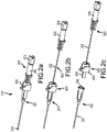
Figs. 3a-3d are cross section views of the safety catheter assembly ofFigs. 1a-2c in each of a ready position (Fig. 3a ), a safe position (Fig. 3b ) and a release position (Figs. 3c and 3d ). -
Figs 4a-4c are perspective views, taken from a distal vantage, of the tip protector assembly ofFigs. 1a-3d in each of a ready position (Fig. 4a ), a safe position (Fig. 4b ) and a release position (Fig. 4c ). The catheter and needle are removed fromFigs. 4a-4c for purposes of illustration. -
Fig. 5 is a perspective view of an inner member of a tip protector assembly, according to one example embodiment. -
Fig. 6 is a perspective view of an outer member of a tip protector assembly, according to one example embodiment. -
Fig. 7 is a perspective view of a retainer of a tip protector assembly, according to one example embodiment. -
Fig. 8 is a perspective view of a collar of a tip protector assembly, according to one example embodiment. -
Fig. 9 is a perspective view of a catheter hub that includes a side port, according to one example embodiment. -
Fig. 10 is a cross sectional view of the catheter hub shown inFig. 9 , along a vertical plane that lies along the needle axis. - The invention is defined by claim 1. Preferred embodiments are defined by the dependent claims. Further examples and embodiments disclosed herein are for exemplary purpose only and do not form part of the invention as claimed.
- Safety catheter assemblies, according to various example embodiments disclosed herein, may be positioned during use in a ready for use position, a safe and engaged position, and a safe and released position. In the ready for use (equivalently referred to herein as the "ready position"), the catheter is assembled to the catheter insertion device with the sharp tip of the needle protruding from a distal end of the catheter tube and the catheter hub secured to the catheter insertion device in a manner that prevents removal therefrom. In the safe and engaged position (equivalently referred to herein as the "safe position") the sharp tip of the insertion needle is positioned internally to a tip protector of the catheter insertion device in order to prevent access to the needle that might otherwise result in unwanted needle sticks. The catheter remains secured to the catheter insertion device when in the safe and engaged position. In the safe and released position (equivalently referred to herein as the "release position") the catheter is disengaged from the catheter insertion device so that the insertion device may be separated from the catheter and disposed of in a safe manner. The sharp tip of the insertion needle remains inaccessible in the release position in order to prevent unwanted needle sticks.
- Turn now to the figures, and initially
Figs. 1a to 3d , which show an example embodiment of asafety catheter assembly 100 that includes acatheter 200, aninsertion needle assembly 300, and a needletip protector assembly 400. Thecatheter 200,insertion needle assembly 300, and needletip protector assembly 400 are shown in each of the ready position (Figs. 1a ,2a , and3a ), the safe position (Figs. 1b ,2b , and3b ), and the release position (Figs. 1c ,2c ,3c, and 3d ), according to one example embodiment. As may be appreciated,Figs. 1a-1c and2a-2c show thesafety catheter assembly 100 in a perspective view taken from distal and proximal vantages, respectively.Figs. 3a-3d are cross sectional views of a portion of the catheter assembly. - The catheter includes a
catheter hub 202 and acatheter tube 204 that cooperate to provide a fluid pathway to the vein of a subject and other IV fluid components, such as an IV fluid supply. Thecatheter tube 204 includes a distal end, a proximal end, and a lumen extending therebetween. The proximal end of thecatheter tube 204 is connected to a distal portion of thecatheter hub 202. Aproximal end 206 of the catheter hub is constructed and arranged to connect to other IV fluid components and may be designed in accordance with ISO standards, according to some embodiments. In the illustrated example embodiment, the proximal end of the catheter hub includes luer lugs, although other constructions are also contemplated. - The
insertion needle assembly 300 includes aninsertion needle 302 having asharp tip 304 that may create an entry passageway into the vein of a subject. The insertion needle extends from a sharpdistal tip 304 to a proximal portion that is connected to aneedle hub 306, and defines an internal lumen that extends therebetween. The proximal portion of the insertion needle is connected to and in fluid communication with theneedle hub 306. The needle hub, in turn, is connected to theflash plug 308 to allow blood to flow from the needle tip to the flash plug. The flash plug may 308 include a microporous barrier that permits the escape of air but prevents the escape of fluid. The body of the insertion needle may include a transition or bump 310 that interacts with the needle tip protector to move the catheter assembly between the ready, safe, and released positions, according to some embodiments. - The illustrated example embodiment also includes a needle tip protector. The
tip protector 400 includes aninner member 402, anouter member 404, aretainer 406, and acollar 408, each of which is shown separately inFigs. 5 to 8 . Theinner member 402 and theouter member 404 of the tip protector cooperate to prevent access to theneedle tip 304 in the safe and released positions. Additionally, theretainer 406 and thecollar 408 cooperate to secure thecatheter 200 to thetip protector assembly 400 in each of the ready and safe positions, while enabling release of the catheter in the release position. - The transition or bump 310 on the body of the
needle 302 acts move thetip protector 400 between the ready, safe, and release positions and may also prevent separation of theinsertion needle assembly 300 from thetip protector assembly 400. Theinner member 402 of thetip protector 404 includesdistal arms 410, aproximal base 412, and abump washer 414. Thebump washer 414 defines aproximal needle stop 416 and aproximal opening 418 that allows passage of theneedle 302 but not thebump 310. When theinsertion needle 302 is pulled proximally between the ready and safe positions, thetransition 310 contacts theproximal needle stop 416 to prevent thetransition 310 from passing through theproximal opening 418, thus preventing separation of theinsertion needle assembly 300 from thetip protector 400. - In the illustrated embodiment, the
proximal needle stop 416 is formed in abump washer 414 that is assembled to the proximal end of theinner member 402. Thebump washer 414 is shaped generally like a traditional washer with the inclusion of adistally extending arm 420 that facilitates connection to other portions of the inner member. The bump washer may be made of a rigid material, such as a metal or plastic that resists deformation when contacted by the transition of the insertion needle. It is to be appreciated that proximal stops, according to alternate example embodiments, may be formed directly in the retainer or in different types of bump washers, such as bump washers that lack a distally extending tab or that are made of materials other than metal. - The
transition 310 may be located on theneedle 302 so that theneedle tip 304 is positioned within theinner member 402 of thetip protector 400 when the transition contacts theproximal stop 416, such that access to the needle tip may be prevented. This may generally be accomplished by locating the transition 310 a distance from theneedle tip 304 that is less than the distance between theproximal stop 416 and thedistal end 422 of theinner member 402. According to some embodiments, the distance between the transition and the needle tip may be smaller than a distance between the proximal stop and a distal stop on the inner member. It is to be appreciated, however, that other configurations are possible, including embodiments where the transition is located on the needle such that the needle tip is positioned internally to the outer member or another component of the tip protector. - Further proximal movement of the
insertion needle 302, once thetransition 310 is in contact with theproximal stop 416, causes theinner member 402 to move proximally relative to theouter member 404 from a distal inner member position to a proximal inner member position, as may be seen in the progression of movement betweenFigs. 3a and 3b . Movement of theinner member 402 within theouter member 404 causesarms 410 of the inner member to move into arestriction 424 of the outer member. Interaction between thearms 410 and theouter member 424 urges the arms toward one another, causes the arms to form adistal needle stop 426 in the passageway previously occupied by theinsertion needle 302. Thedistal needle stop 426 prevents distal movement of the needle from outside of the interior of the inner member, and thus protects clinicians and others from the sharp needle tip. - The arms of the inner member may include protrusions or ribs that engage one another to form the distal needle stop when the inner member is in the proximal inner member position, such as when the tip protector assembly is in either of the safe or release positions. These or other features of the arms may contact one another, fully occupying the needle passageway to form the distal needle stop, as shown in
Fig. 3b . It is to be appreciated, however, that other embodiments may lack such fingers or ribs. It is also to be appreciated that the distal needle stop may not fully occupy the needle passageway when in the safe position, according to alternate embodiments. In one such alternate embodiment, the arms of the inner member are urged toward one another to form a distal needle stop that restricts passage of the sharp needle tip without fully occupying the needle passageway. - The
distal arms 410 of the inner member may be biased in the radially outward direction, away from one another. Such a bias may promote separation of thedistal arms 410 from one another and thus from theinsertion needle 302 prior to the needle reaching the safe position. Such separation may minimize friction between theinsertion needle 302 andinner member 402, promoting easy movement of the insertion needle from the ready position to the safe position. According to some embodiments, the inner member is made of a resilient rubber or plastic material. - The
distal arms 410 may include ahinge area 428 near a connection to theproximal base 412 and an enlargeddistal portion 430. The hinge area may promote flexing of the distal arms between the ready position and the safe position. The enlargeddistal portions 430 may be shaped and sized to form thedistal needle stop 426 when moved inwards or toward one another by therestriction 424 of the outer member. In the illustrated embodiment, the distal portion of at least one of the arms includes aramp structure 432 that interacts with theouter member 404 to urge the arm inward 410, toward the needle passageway, as the inner member is pulled proximally by movement of the insertion needle. - The inner member includes a
safe position lock 434 that prevents distal movement of the inner member, once in the inner member proximal position relative to the outer member. In the illustrated example embodiment, thelock 434 includes a distally facing innermember lock surface 436 that interacts with an inwardlybiased tab 438 of theouter member 404. Proximal movement of theinner member 402 brings the lock surface into engagement with a proximally facing lock surface of thetab 438. Once engaged, the lock surfaces 436 of theinner member 402 and thetab 438 prevent emergence of theneedle tip 304 by preventing theinner member 402 from returning to the distal inner member position. It is to be appreciated that the safe position lock shown in the illustrated example embodiment is but one type of lock and that others are also contemplated. - As may be seen in
Figs. 3a and 3b , in each of the ready and safe positions thecatheter 200 is secured to theneedle tip protector 400 in a manner that prevents separation, with theretainer 406 in a distal retainer position relative to thecollar 408. This is accomplished by various engagement features in theneedle tip protector 400 that secure thecatheter 200 to the tip protector until the tip protector is in the release position. In the illustrated embodiment, external engagement features are located on the collar and the retainer. The outer member may additionally provide internal engagement features that help to secure the catheter to the tip protector. - The
collar 408 includes anotch 440 that receives afirst luer lug 208 of thecatheter hub 202. Thenotch 440 engages a forward facing surface of the luer lug to prevent the lug and thus the catheter from moving distally away from the tip protector assembly. Contact between a notch and the first luer lug of the catheter may also prevent the catheter hub from moving laterally away from the tip protector. - External engagement features are provided by the retainer, in the illustrated example embodiment. The retainer includes a base and a lateral wall that form a pocket that receives the proximal end of the catheter hub. Inner portions of the catheter wall engage corresponding outer surfaces of the catheter hub to secure the catheter to the tip protector assembly. Although the retainer is shown to have a pocket with a shape that corresponds to that of the proximal end of the catheter, it is to be appreciated that other configurations are also contemplated, such as configurations that engage the second luer lug of the catheter hub.
- The outer member of the needle tip protector assembly may, according to some embodiments, contact the interior of the catheter hub to provide an interior engagement. By way of example, the outer member may be sized such that a sliding surface of the outer wall makes contact with the interior of the catheter hub. This contact may prevent the catheter hub from moving laterally with respect to the outer member and other portions of the tip protector without directly preventing distal movement of the catheter. According to other embodiments, the outer member may be shaped and sized such that there is no contact between the outer member and the catheter hub.
- With the tip protector assembly in the safe position and the inner member in contact with the proximal wall of the outer member, further proximal movement of the insertion needle causes the retainer, and other components of the tip protector, to move proximally relative to the collar to a proximal retainer position. This motion causes external engagement features of the retainer to move proximally away from the corresponding outer surfaces of the catheter hub, as shown in the progression of movement between
Figs. 3b and 3c . The sliding surface of the outer member is also moved proximally and out of contact with the inner surface of the catheter hub, at least in embodiments that include contact between the catheter hub and inner member. - The tip protector may include a feature that resists proximal movement of the retainer to the proximal release position prior to being in the safe position. The illustrated example embodiment includes a retention finger that is integrated into the collar and that includes a spring arm and a retention tab. The retention tab is positioned proximally to the retainer. Proximal movement of the retainer is resisted by the retention tab, until the forces associated with flexing the spring arm and retention tab away from the retainer are overcome. In this respect, the
retention tab 442 of thecollar 408 provides a release threshold force that is to be overcome prior to thecatheter 200 being released from thetip protection assembly 400. - The release threshold force may be higher than the forces associated with movement from the ready position to the safe position (i.e., the safety threshold force), according to some embodiments. Having the release threshold force higher than the safe threshold force may prevent the catheter from being released prior to the tip protection assembly being moved to the safe position. The release threshold force, according to some embodiments, is more than 2x the safety threshold force, more than 3x the safety threshold force, or more than 5x the safety threshold force.
- The
catheter hub 202 is released from secure connection to thetip protection assembly 400 when the external engagement features of theretainer 406 are out of engagement with thecatheter hub 202, as shown inFig. 3c . In this position, the further proximal movement of theinsertion needle assembly 300 will pull theneedle tip protector 400 away from thecatheter hub 202, as reflect inFig. 3d . Separation of thecollar 408 from thecatheter hub 202 may be accompanied by a slight jogging of the tip protector in a lateral direction, away from the needle passage, according to some embodiments. The sloped shape of the luer lug and/or the notch may promote this motion. Additionally or alternately, the clinician may tilt pull on the insertion needle assembly at an upward angle to promote separation of the catheter from the collar. - The catheter hub may include a
side port 500, such as in the example embodiment ofFigures 9 and 10 . As shown, thecatheter hub 202 includes a side port that may be accessed through a lateral, luer type connection that is integrated into the catheter hub. Aside port cap 502 may be selectively positioned over the side port to close and open access thereto, as desired. A flexible, cylindrically shaped septum is positioned internally to the catheter hub. Theseptum 504 is moved away from the side port by pressurized fluid that is introduced into the luer to allow the pressurized fluid to enter the catheter hub. In the absence of pressurized fluid in the luer, the septum closes access to the side port to prevent the escape of fluids from the catheter. - Various example embodiments of catheters are described herein for use in accessing the vein of a subject. It is to be appreciated, however, that the example embodiments described herein may alternately be used to access the vasculature of a subject at locations other than a vein, including but not limited to the artery of a subject. It is additionally to be appreciated that the term "clinician" refers to any individual that may be performing a catheter insertion procedure with any of the example embodiments described herein or combinations thereof. Similarly, the term "subject", as used herein, is to be understood to refer to an individual or object in which a catheter is to be inserted, whether human, animal, or inanimate. Various descriptions are made herein, for the sake of convenience, with respect to procedures being performed by a clinician to access the vein of a subject, while the disclosure is not limited in this respect.
- It is also to be appreciated that the term "distal", as used herein, refers to the direction, taking along an axis that lies parallel to the needle of a safety catheter assembly that is closest to a subject during catheter insertion. Conversely, the term "proximal", as used herein, refers the direction lying along the axis parallel to the needle that is farther away from the subject when the catheter is inserted into the vein of the subject - that is, opposite to the distal direction.
- The foregoing description of example embodiments has been presented for the purposes of illustration and description. It is not intended to be exhaustive or to limit the present disclosure to the precise forms disclosed. Many modifications and variations are possible in light of this disclosure. It is intended that the scope of the present disclosure be limited not by this detailed description, but rather by the claims appended hereto. Future-filed applications claiming priority to this application may claim the disclosed subject matter in a different manner and generally may include any set of one or more features as variously disclosed or otherwise demonstrated herein.
Claims (15)
- A safety catheter comprising:a catheter (200) including a catheter tube (204) and a catheter hub (202);an insertion needle assembly (300) including an insertion needle (302) having a sharp distal tip (304) and a proximal end; anda tip protector assembly (400) having an inner member (402), an outer member (404), a retainer (406) and a collar (408), the inner member (402) having distal arms (410) and being movable within the outer member (404) between a distal inner member position and a proximal inner member position, the retainer (406) being movable between a distal retainer position and a proximal retainer position;wherein the tip protector assembly (400) is changeable between a ready position, a safe position, and a release position;wherein in the ready position, the retainer (406) is in the distal retainer position and the retainer (406) and the collar (408) cooperate to prevent separation of the tip protector assembly (400) from the catheter hub (202);wherein in the safe position, the inner member (402) is in the proximal inner member position, the distal arms (410) form a distal needle stop (426) that prevents distal movement of the insertion needle (302), the retainer (406) is in the distal retainer position, and the retainer (406) and collar (408) cooperate to prevent separation of the tip protector assembly (400) from the catheter hub (202); andwherein in the release position, the retainer (406) is in the proximal retainer position and the tip protector assembly (400) is separable from the catheter hub (202).
- The safety catheter of claim 1, wherein the tip protector assembly (400) changes sequentially from the ready to safe to release positions during proximal withdrawal of the insertion needle (302) from the catheter (200).
- The safety catheter of claim 2, wherein the insertion needle (302) further includes a needle transition (310) axially spaced apart from the sharp distal tip (304) by a transition distance.
- The safety catheter of claim 3, wherein the inner member (402) includes a metal washer that prevents proximal passage of the needle transition (310) from the tip protector assembly (400).
- The safety catheter of claim 3, wherein the needle transition (310) engages a proximal stop (416) of the inner member causing the inner member to move from the distal inner member position to the proximal inner member position during proximal withdrawal of the insertion needle (302) from the catheter (200).
- The safety catheter of claim 5, wherein continued proximal withdrawal of the insertion needle (302) from the catheter (200) causes the needle transition (310) to move the retainer (406) from the retainer distal retainer position to the proximal retainer position.
- The safety catheter of claim 5, wherein the inner member (402) has a length between a distal end of the inner member (402) and the proximal stop (416) that is greater than the transition distance.
- The safety catheter of claim 1, wherein the inner member (402) includes a lock (434) that prevents distal movement of the inner member (402) once the inner member (402) is in the proximal inner member position.
- The safety catheter of claim 1, wherein the inner member (402) encloses the sharp distal tip (304) of the insertion needle (302) when the inner member (402) is in the proximal inner member position.
- The safety catheter of claim 1, wherein the distal arms (410) move to enclose the sharp distal tip (304) of the insertion needle (302) when the inner member (402) moves from the distal inner member position to the proximal inner member position.
- The safety catheter of claim 1, wherein the distal needle stop (426) prevents distal movement of the sharp distal tip (304) from the tip protector assembly (400).
- The safety catheter of claim 1, wherein the retainer (406) is fixedly connected to the outer member (404) and the outer member (404) moves with the retainer (406) from the distal retainer position to the proximal retainer position.
- The safety catheter of claim 1, wherein the catheter hub (202) is retained to the tip protector assembly (400) by engagement between inner portions of the catheter hub (202) and the outer member (404) when the tip protector assembly (400) is in the safe position.
- The safety catheter of claim 1, wherein the collar (408) includes a retention finger that resists movement of the retainer (406) to the proximal retainer position.
- The safety catheter of claim 1, wherein the catheter (200) further comprises a side port (500).
Applications Claiming Priority (3)
| Application Number | Priority Date | Filing Date | Title |
|---|---|---|---|
| US201762475428P | 2017-03-23 | 2017-03-23 | |
| EP18771336.7A EP3568189B1 (en) | 2017-03-23 | 2018-03-21 | Safety catheter with passive release |
| PCT/US2018/023550 WO2018175573A1 (en) | 2017-03-23 | 2018-03-21 | Safety catheter with passive release |
Related Parent Applications (2)
| Application Number | Title | Priority Date | Filing Date |
|---|---|---|---|
| EP18771336.7A Division-Into EP3568189B1 (en) | 2017-03-23 | 2018-03-21 | Safety catheter with passive release |
| EP18771336.7A Division EP3568189B1 (en) | 2017-03-23 | 2018-03-21 | Safety catheter with passive release |
Publications (2)
| Publication Number | Publication Date |
|---|---|
| EP3854439A1 EP3854439A1 (en) | 2021-07-28 |
| EP3854439B1 true EP3854439B1 (en) | 2022-04-06 |
Family
ID=63586203
Family Applications (2)
| Application Number | Title | Priority Date | Filing Date |
|---|---|---|---|
| EP18771336.7A Active EP3568189B1 (en) | 2017-03-23 | 2018-03-21 | Safety catheter with passive release |
| EP21155603.0A Active EP3854439B1 (en) | 2017-03-23 | 2018-03-21 | Safety catheter with passive release |
Family Applications Before (1)
| Application Number | Title | Priority Date | Filing Date |
|---|---|---|---|
| EP18771336.7A Active EP3568189B1 (en) | 2017-03-23 | 2018-03-21 | Safety catheter with passive release |
Country Status (3)
| Country | Link |
|---|---|
| US (3) | US10543341B2 (en) |
| EP (2) | EP3568189B1 (en) |
| WO (1) | WO2018175573A1 (en) |
Families Citing this family (2)
| Publication number | Priority date | Publication date | Assignee | Title |
|---|---|---|---|---|
| US20200338314A1 (en) * | 2019-04-23 | 2020-10-29 | Smiths Medical Asd, Inc. | Catheter insertion device with improved push tab and tip protector assembly |
| CN213252024U (en) * | 2019-09-10 | 2021-05-25 | 贝克顿·迪金森公司 | Vascular access system and clamping device |
Family Cites Families (7)
| Publication number | Priority date | Publication date | Assignee | Title |
|---|---|---|---|---|
| US6595954B1 (en) * | 2000-03-13 | 2003-07-22 | Luther Research Partners, Llc | Insertion needle and soft catheter system with tip protector |
| US20070038187A1 (en) | 2005-08-08 | 2007-02-15 | Albert Sean J | Needle guard mechanism with anti-rotation feature |
| US8398597B2 (en) * | 2008-06-17 | 2013-03-19 | Becton, Dickinson And Company | Needle shield and interlock |
| US8257322B2 (en) | 2010-06-02 | 2012-09-04 | Smiths Medical Asd, Inc. | Tip protector for a safety catheter |
| JP6138921B2 (en) | 2013-04-01 | 2017-05-31 | テルモ株式会社 | Catheter assembly |
| WO2014196243A1 (en) * | 2013-06-06 | 2014-12-11 | テルモ株式会社 | Catheter assembly |
| US9555221B2 (en) * | 2014-04-10 | 2017-01-31 | Smiths Medical Asd, Inc. | Constant force hold tip protector for a safety catheter |
-
2018
- 2018-03-21 EP EP18771336.7A patent/EP3568189B1/en active Active
- 2018-03-21 WO PCT/US2018/023550 patent/WO2018175573A1/en unknown
- 2018-03-21 US US16/065,578 patent/US10543341B2/en active Active
- 2018-03-21 EP EP21155603.0A patent/EP3854439B1/en active Active
-
2019
- 2019-12-17 US US16/717,063 patent/US11590324B2/en active Active
-
2023
- 2023-01-12 US US18/096,149 patent/US11931533B2/en active Active
Also Published As
| Publication number | Publication date |
|---|---|
| US11931533B2 (en) | 2024-03-19 |
| WO2018175573A1 (en) | 2018-09-27 |
| EP3568189B1 (en) | 2021-04-21 |
| EP3568189A1 (en) | 2019-11-20 |
| US11590324B2 (en) | 2023-02-28 |
| US20190374749A1 (en) | 2019-12-12 |
| US10543341B2 (en) | 2020-01-28 |
| US20230149666A1 (en) | 2023-05-18 |
| EP3854439A1 (en) | 2021-07-28 |
| US20200121895A1 (en) | 2020-04-23 |
| EP3568189A4 (en) | 2020-02-19 |
Similar Documents
| Publication | Publication Date | Title |
|---|---|---|
| CN111032136B (en) | Method and device for accessing a blood vessel | |
| CA2728010C (en) | Telescopic needle shield with interlock | |
| AU2016211195B2 (en) | Releaseable catheter hub retainer | |
| JP2019055264A (en) | Ported iv catheter having external needle shield and internal blood control septum | |
| US20210100985A1 (en) | Releasable safety catheter insertion assembly | |
| US11931533B2 (en) | Safety catheter with passive release | |
| WO2013016373A1 (en) | Vascular access assembly and safety device | |
| WO2014140265A1 (en) | Valved catheter assemblies | |
| BRPI1012701B1 (en) | needle tip protection mechanism, catheter assembly and method for using a needle tip protection mechanism | |
| AU2006203663B2 (en) | Catheter and introducer needle assembly with safety device | |
| EP3773856A1 (en) | Iv catheter with a tip protector | |
| AU2020286296B2 (en) | Blood containment for IV catheter | |
| EP1292355B1 (en) | Catheter and introducer needle assembly with needle shield | |
| CN215740987U (en) | Venous device assembly and vascular access device |
Legal Events
| Date | Code | Title | Description |
|---|---|---|---|
| PUAI | Public reference made under article 153(3) epc to a published international application that has entered the european phase |
Free format text: ORIGINAL CODE: 0009012 |
|
| STAA | Information on the status of an ep patent application or granted ep patent |
Free format text: STATUS: THE APPLICATION HAS BEEN PUBLISHED |
|
| AC | Divisional application: reference to earlier application |
Ref document number: 3568189 Country of ref document: EP Kind code of ref document: P |
|
| AK | Designated contracting states |
Kind code of ref document: A1 Designated state(s): AL AT BE BG CH CY CZ DE DK EE ES FI FR GB GR HR HU IE IS IT LI LT LU LV MC MK MT NL NO PL PT RO RS SE SI SK SM TR |
|
| STAA | Information on the status of an ep patent application or granted ep patent |
Free format text: STATUS: REQUEST FOR EXAMINATION WAS MADE |
|
| 17P | Request for examination filed |
Effective date: 20210908 |
|
| RBV | Designated contracting states (corrected) |
Designated state(s): AL AT BE BG CH CY CZ DE DK EE ES FI FR GB GR HR HU IE IS IT LI LT LU LV MC MK MT NL NO PL PT RO RS SE SI SK SM TR |
|
| GRAP | Despatch of communication of intention to grant a patent |
Free format text: ORIGINAL CODE: EPIDOSNIGR1 |
|
| STAA | Information on the status of an ep patent application or granted ep patent |
Free format text: STATUS: GRANT OF PATENT IS INTENDED |
|
| RIC1 | Information provided on ipc code assigned before grant |
Ipc: A61M 25/06 20060101AFI20211031BHEP |
|
| INTG | Intention to grant announced |
Effective date: 20211125 |
|
| GRAS | Grant fee paid |
Free format text: ORIGINAL CODE: EPIDOSNIGR3 |
|
| GRAA | (expected) grant |
Free format text: ORIGINAL CODE: 0009210 |
|
| STAA | Information on the status of an ep patent application or granted ep patent |
Free format text: STATUS: THE PATENT HAS BEEN GRANTED |
|
| AC | Divisional application: reference to earlier application |
Ref document number: 3568189 Country of ref document: EP Kind code of ref document: P |
|
| AK | Designated contracting states |
Kind code of ref document: B1 Designated state(s): AL AT BE BG CH CY CZ DE DK EE ES FI FR GB GR HR HU IE IS IT LI LT LU LV MC MK MT NL NO PL PT RO RS SE SI SK SM TR |
|
| REG | Reference to a national code |
Ref country code: GB Ref legal event code: FG4D |
|
| REG | Reference to a national code |
Ref country code: CH Ref legal event code: EP |
|
| REG | Reference to a national code |
Ref country code: AT Ref legal event code: REF Ref document number: 1480717 Country of ref document: AT Kind code of ref document: T Effective date: 20220415 |
|
| REG | Reference to a national code |
Ref country code: IE Ref legal event code: FG4D |
|
| REG | Reference to a national code |
Ref country code: DE Ref legal event code: R096 Ref document number: 602018033639 Country of ref document: DE |
|
| REG | Reference to a national code |
Ref country code: LT Ref legal event code: MG9D |
|
| REG | Reference to a national code |
Ref country code: NL Ref legal event code: MP Effective date: 20220406 |
|
| REG | Reference to a national code |
Ref country code: AT Ref legal event code: MK05 Ref document number: 1480717 Country of ref document: AT Kind code of ref document: T Effective date: 20220406 |
|
| PG25 | Lapsed in a contracting state [announced via postgrant information from national office to epo] |
Ref country code: NL Free format text: LAPSE BECAUSE OF FAILURE TO SUBMIT A TRANSLATION OF THE DESCRIPTION OR TO PAY THE FEE WITHIN THE PRESCRIBED TIME-LIMIT Effective date: 20220406 |
|
| PG25 | Lapsed in a contracting state [announced via postgrant information from national office to epo] |
Ref country code: SE Free format text: LAPSE BECAUSE OF FAILURE TO SUBMIT A TRANSLATION OF THE DESCRIPTION OR TO PAY THE FEE WITHIN THE PRESCRIBED TIME-LIMIT Effective date: 20220406 Ref country code: PT Free format text: LAPSE BECAUSE OF FAILURE TO SUBMIT A TRANSLATION OF THE DESCRIPTION OR TO PAY THE FEE WITHIN THE PRESCRIBED TIME-LIMIT Effective date: 20220808 Ref country code: NO Free format text: LAPSE BECAUSE OF FAILURE TO SUBMIT A TRANSLATION OF THE DESCRIPTION OR TO PAY THE FEE WITHIN THE PRESCRIBED TIME-LIMIT Effective date: 20220706 Ref country code: LT Free format text: LAPSE BECAUSE OF FAILURE TO SUBMIT A TRANSLATION OF THE DESCRIPTION OR TO PAY THE FEE WITHIN THE PRESCRIBED TIME-LIMIT Effective date: 20220406 Ref country code: HR Free format text: LAPSE BECAUSE OF FAILURE TO SUBMIT A TRANSLATION OF THE DESCRIPTION OR TO PAY THE FEE WITHIN THE PRESCRIBED TIME-LIMIT Effective date: 20220406 Ref country code: GR Free format text: LAPSE BECAUSE OF FAILURE TO SUBMIT A TRANSLATION OF THE DESCRIPTION OR TO PAY THE FEE WITHIN THE PRESCRIBED TIME-LIMIT Effective date: 20220707 Ref country code: FI Free format text: LAPSE BECAUSE OF FAILURE TO SUBMIT A TRANSLATION OF THE DESCRIPTION OR TO PAY THE FEE WITHIN THE PRESCRIBED TIME-LIMIT Effective date: 20220406 Ref country code: ES Free format text: LAPSE BECAUSE OF FAILURE TO SUBMIT A TRANSLATION OF THE DESCRIPTION OR TO PAY THE FEE WITHIN THE PRESCRIBED TIME-LIMIT Effective date: 20220406 Ref country code: BG Free format text: LAPSE BECAUSE OF FAILURE TO SUBMIT A TRANSLATION OF THE DESCRIPTION OR TO PAY THE FEE WITHIN THE PRESCRIBED TIME-LIMIT Effective date: 20220706 Ref country code: AT Free format text: LAPSE BECAUSE OF FAILURE TO SUBMIT A TRANSLATION OF THE DESCRIPTION OR TO PAY THE FEE WITHIN THE PRESCRIBED TIME-LIMIT Effective date: 20220406 |
|
| PG25 | Lapsed in a contracting state [announced via postgrant information from national office to epo] |
Ref country code: RS Free format text: LAPSE BECAUSE OF FAILURE TO SUBMIT A TRANSLATION OF THE DESCRIPTION OR TO PAY THE FEE WITHIN THE PRESCRIBED TIME-LIMIT Effective date: 20220406 Ref country code: PL Free format text: LAPSE BECAUSE OF FAILURE TO SUBMIT A TRANSLATION OF THE DESCRIPTION OR TO PAY THE FEE WITHIN THE PRESCRIBED TIME-LIMIT Effective date: 20220406 Ref country code: LV Free format text: LAPSE BECAUSE OF FAILURE TO SUBMIT A TRANSLATION OF THE DESCRIPTION OR TO PAY THE FEE WITHIN THE PRESCRIBED TIME-LIMIT Effective date: 20220406 Ref country code: IS Free format text: LAPSE BECAUSE OF FAILURE TO SUBMIT A TRANSLATION OF THE DESCRIPTION OR TO PAY THE FEE WITHIN THE PRESCRIBED TIME-LIMIT Effective date: 20220806 |
|
| REG | Reference to a national code |
Ref country code: DE Ref legal event code: R097 Ref document number: 602018033639 Country of ref document: DE |
|
| PG25 | Lapsed in a contracting state [announced via postgrant information from national office to epo] |
Ref country code: SM Free format text: LAPSE BECAUSE OF FAILURE TO SUBMIT A TRANSLATION OF THE DESCRIPTION OR TO PAY THE FEE WITHIN THE PRESCRIBED TIME-LIMIT Effective date: 20220406 Ref country code: SK Free format text: LAPSE BECAUSE OF FAILURE TO SUBMIT A TRANSLATION OF THE DESCRIPTION OR TO PAY THE FEE WITHIN THE PRESCRIBED TIME-LIMIT Effective date: 20220406 Ref country code: RO Free format text: LAPSE BECAUSE OF FAILURE TO SUBMIT A TRANSLATION OF THE DESCRIPTION OR TO PAY THE FEE WITHIN THE PRESCRIBED TIME-LIMIT Effective date: 20220406 Ref country code: EE Free format text: LAPSE BECAUSE OF FAILURE TO SUBMIT A TRANSLATION OF THE DESCRIPTION OR TO PAY THE FEE WITHIN THE PRESCRIBED TIME-LIMIT Effective date: 20220406 Ref country code: DK Free format text: LAPSE BECAUSE OF FAILURE TO SUBMIT A TRANSLATION OF THE DESCRIPTION OR TO PAY THE FEE WITHIN THE PRESCRIBED TIME-LIMIT Effective date: 20220406 Ref country code: CZ Free format text: LAPSE BECAUSE OF FAILURE TO SUBMIT A TRANSLATION OF THE DESCRIPTION OR TO PAY THE FEE WITHIN THE PRESCRIBED TIME-LIMIT Effective date: 20220406 |
|
| PLBE | No opposition filed within time limit |
Free format text: ORIGINAL CODE: 0009261 |
|
| STAA | Information on the status of an ep patent application or granted ep patent |
Free format text: STATUS: NO OPPOSITION FILED WITHIN TIME LIMIT |
|
| 26N | No opposition filed |
Effective date: 20230110 |
|
| PG25 | Lapsed in a contracting state [announced via postgrant information from national office to epo] |
Ref country code: AL Free format text: LAPSE BECAUSE OF FAILURE TO SUBMIT A TRANSLATION OF THE DESCRIPTION OR TO PAY THE FEE WITHIN THE PRESCRIBED TIME-LIMIT Effective date: 20220406 |
|
| PGFP | Annual fee paid to national office [announced via postgrant information from national office to epo] |
Ref country code: IT Payment date: 20230213 Year of fee payment: 6 Ref country code: GB Payment date: 20230126 Year of fee payment: 6 Ref country code: DE Payment date: 20230125 Year of fee payment: 6 |
|
| P01 | Opt-out of the competence of the unified patent court (upc) registered |
Effective date: 20230419 |
|
| PG25 | Lapsed in a contracting state [announced via postgrant information from national office to epo] |
Ref country code: MC Free format text: LAPSE BECAUSE OF FAILURE TO SUBMIT A TRANSLATION OF THE DESCRIPTION OR TO PAY THE FEE WITHIN THE PRESCRIBED TIME-LIMIT Effective date: 20220406 |
|
| REG | Reference to a national code |
Ref country code: CH Ref legal event code: PL |
|
| REG | Reference to a national code |
Ref country code: BE Ref legal event code: MM Effective date: 20230331 |
|
| PG25 | Lapsed in a contracting state [announced via postgrant information from national office to epo] |
Ref country code: LU Free format text: LAPSE BECAUSE OF NON-PAYMENT OF DUE FEES Effective date: 20230321 |
|
| REG | Reference to a national code |
Ref country code: IE Ref legal event code: MM4A |
|
| PG25 | Lapsed in a contracting state [announced via postgrant information from national office to epo] |
Ref country code: LI Free format text: LAPSE BECAUSE OF NON-PAYMENT OF DUE FEES Effective date: 20230331 Ref country code: IE Free format text: LAPSE BECAUSE OF NON-PAYMENT OF DUE FEES Effective date: 20230321 Ref country code: CH Free format text: LAPSE BECAUSE OF NON-PAYMENT OF DUE FEES Effective date: 20230331 |
|
| PGFP | Annual fee paid to national office [announced via postgrant information from national office to epo] |
Ref country code: FR Payment date: 20231229 Year of fee payment: 7 |
|
| PG25 | Lapsed in a contracting state [announced via postgrant information from national office to epo] |
Ref country code: BE Free format text: LAPSE BECAUSE OF NON-PAYMENT OF DUE FEES Effective date: 20230331 |