EP3854327A1 - Dilator - Google Patents
Dilator Download PDFInfo
- Publication number
- EP3854327A1 EP3854327A1 EP18934183.7A EP18934183A EP3854327A1 EP 3854327 A1 EP3854327 A1 EP 3854327A1 EP 18934183 A EP18934183 A EP 18934183A EP 3854327 A1 EP3854327 A1 EP 3854327A1
- Authority
- EP
- European Patent Office
- Prior art keywords
- protruding portion
- coil
- dilator
- hollow shaft
- peripheral surface
- Prior art date
- Legal status (The legal status is an assumption and is not a legal conclusion. Google has not performed a legal analysis and makes no representation as to the accuracy of the status listed.)
- Granted
Links
Images


Classifications
-
- A—HUMAN NECESSITIES
- A61—MEDICAL OR VETERINARY SCIENCE; HYGIENE
- A61B—DIAGNOSIS; SURGERY; IDENTIFICATION
- A61B17/00—Surgical instruments, devices or methods
- A61B17/34—Trocars; Puncturing needles
- A61B17/3417—Details of tips or shafts, e.g. grooves, expandable, bendable; Multiple coaxial sliding cannulas, e.g. for dilating
- A61B17/3421—Cannulas
- A61B17/3423—Access ports, e.g. toroid shape introducers for instruments or hands
-
- A—HUMAN NECESSITIES
- A61—MEDICAL OR VETERINARY SCIENCE; HYGIENE
- A61B—DIAGNOSIS; SURGERY; IDENTIFICATION
- A61B17/00—Surgical instruments, devices or methods
- A61B17/34—Trocars; Puncturing needles
- A61B17/3417—Details of tips or shafts, e.g. grooves, expandable, bendable; Multiple coaxial sliding cannulas, e.g. for dilating
- A61B17/3421—Cannulas
-
- A—HUMAN NECESSITIES
- A61—MEDICAL OR VETERINARY SCIENCE; HYGIENE
- A61M—DEVICES FOR INTRODUCING MEDIA INTO, OR ONTO, THE BODY; DEVICES FOR TRANSDUCING BODY MEDIA OR FOR TAKING MEDIA FROM THE BODY; DEVICES FOR PRODUCING OR ENDING SLEEP OR STUPOR
- A61M29/00—Dilators with or without means for introducing media, e.g. remedies
-
- A—HUMAN NECESSITIES
- A61—MEDICAL OR VETERINARY SCIENCE; HYGIENE
- A61B—DIAGNOSIS; SURGERY; IDENTIFICATION
- A61B17/00—Surgical instruments, devices or methods
- A61B17/34—Trocars; Puncturing needles
- A61B17/3417—Details of tips or shafts, e.g. grooves, expandable, bendable; Multiple coaxial sliding cannulas, e.g. for dilating
- A61B17/3421—Cannulas
- A61B17/3423—Access ports, e.g. toroid shape introducers for instruments or hands
- A61B2017/3425—Access ports, e.g. toroid shape introducers for instruments or hands for internal organs, e.g. heart ports
-
- A—HUMAN NECESSITIES
- A61—MEDICAL OR VETERINARY SCIENCE; HYGIENE
- A61B—DIAGNOSIS; SURGERY; IDENTIFICATION
- A61B17/00—Surgical instruments, devices or methods
- A61B17/34—Trocars; Puncturing needles
- A61B17/3417—Details of tips or shafts, e.g. grooves, expandable, bendable; Multiple coaxial sliding cannulas, e.g. for dilating
- A61B17/3421—Cannulas
- A61B2017/3433—Cannulas with different outer diameters of the cannula
-
- A—HUMAN NECESSITIES
- A61—MEDICAL OR VETERINARY SCIENCE; HYGIENE
- A61B—DIAGNOSIS; SURGERY; IDENTIFICATION
- A61B17/00—Surgical instruments, devices or methods
- A61B17/34—Trocars; Puncturing needles
- A61B2017/348—Means for supporting the trocar against the body or retaining the trocar inside the body
- A61B2017/3482—Means for supporting the trocar against the body or retaining the trocar inside the body inside
- A61B2017/349—Trocar with thread on outside
-
- A—HUMAN NECESSITIES
- A61—MEDICAL OR VETERINARY SCIENCE; HYGIENE
- A61M—DEVICES FOR INTRODUCING MEDIA INTO, OR ONTO, THE BODY; DEVICES FOR TRANSDUCING BODY MEDIA OR FOR TAKING MEDIA FROM THE BODY; DEVICES FOR PRODUCING OR ENDING SLEEP OR STUPOR
- A61M25/00—Catheters; Hollow probes
- A61M25/0043—Catheters; Hollow probes characterised by structural features
- A61M25/005—Catheters; Hollow probes characterised by structural features with embedded materials for reinforcement, e.g. wires, coils, braids
Definitions
- the present invention relates to a dilator.
- Dilators are known for expanding a hole formed on the wall of a patient's digestive tract and the like for the purpose of treatment.
- the distal end of the dilator is inserted into the hole formed on the wall, and the hole is expanded by pushing a tapered portion into the hole.
- Such a dilator is, for example, disclosed in Patent Literature 1.
- Patent Literature 1 Japanese Unexamined Patent Application Publication No. 2008-11867
- a sufficient propulsive force cannot be achieved at the tapered portion where the pushing resistance with respect to a hole or a constricted part increases, and the dilator could not sufficiently expand the hole in some cases. Therefore, a configuration can be considered where a spirally-arranged protruding portion is formed by winding a coil around the outer periphery of the dilator, and the dilator is advanced by ensuring a propulsive force is obtained due to a screw effect caused by rotation.
- the protruding portion that extends in a spiral may become displaced in a lengthwise axis direction.
- the present invention has an object of providing a dilator that can suppress displacement, in a lengthwise axis direction, of a protruding portion that extends in a spiral.
- a dilator comprises: a hollow shaft having an outer diameter that increases from a distal end toward a proximal end; and a protruding portion that is provided on an outer periphery of the hollow shaft, and extends along the outer periphery of the hollow shaft in a spiral along a lengthwise axis direction of the hollow shaft; wherein the protruding portion has gaps between adjacent parts of the protruding portions along the lengthwise axis direction, a covering layer is provided that covers at least an outer peripheral surface of the hollow shaft, the outer peripheral surface being located in the gaps, and a top portion of the protruding portion is exposed.
- the protruding portion may be provided so as to make contact with the outer peripheral surface of the hollow shaft, and the covering layer may be located between adjacent parts of the protruding portion, and make contact with an outer peripheral surface of the protruding portion.
- the covering layer may cover the outer peripheral surface of the hollow shaft, and the protruding portion may be provided on the covering layer.
- the hollow shaft may comprise a first coil, in which one or more wires are wound into a hollow shape, and the protruding portion may comprise a second coil, in which one or more wires are wound around the outer peripheral surface of the hollow shaft.
- a dilator can be provided that can suppress displacement, in a lengthwise axis direction, of a protruding portion that extends in a spiral.
- FIG. 1 is an overall view of a dilator 1 according to an embodiment of the present invention.
- FIG. 2 is a cross-sectional view of the vicinity of a boundary between a tapered portion 2D and a proximal end portion 2C of the dilator 1 according to the present embodiment.
- the left side of the drawing is the distal end side (distal side) inserted into the body, and the right side is the proximal end side (hand side, proximal side) operated by an operator such as a physician.
- the dilator 1 comprises: a multilayered body 4 configured by a first coil 2 formed by winding one or more metal wires into a hollow shape, and a second coil 3 formed by winding a single metal wire around an outer peripheral surface 2A of the first coil 2 in the opposite direction (Z-twisted) to the first coil 2 (S-twisted); a covering layer 5 that covers the outer peripheral surface 2A of the first coil 2; and a hollow connector 6 connected to the proximal end of the multilayered body 4.
- the second coil 3 may be configured by a plurality of metal wires.
- the wires constituting the first coil 2 and the second coil 3 are, for example, metal wires made of stainless steel or a superelastic alloy such as nickel-titanium, or are resin wires.
- the first coil 2 is formed, for example, by winding ten metal wires made of stainless steel.
- the first coil 2 has a hollow shape, and is formed having a lumen 2B that passes through from the proximal end to the distal end.
- the first coil 2 includes a proximal end portion 2C, a tapered portion 2D, and a distal end portion 2E.
- the first coil 2 corresponds to a hollow shaft.
- the proximal end portion 2C is located on the proximal end side of the dilator 1, and a connector 6 is connected to the proximal end thereof. Furthermore, the proximal end portion 2C has a substantially constant outer diameter from the proximal end to the distal end.
- the tapered portion 2D is located on the distal end side of the proximal end portion 2C, extends from the distal end of the proximal end portion 2C toward the distal end side, and has an outer diameter that decreases toward the distal end side.
- the distal end portion 2E is located on the distal end side of the tapered portion 2D, and extends from the distal end of the tapered portion 2D toward the distal end side.
- the distal end portion 2E has a substantially constant outer diameter from the proximal end to the distal end thereof. In this way, the outer diameter of the first coil 2, which is a hollow shaft, increases from the distal end toward the proximal end.
- the second coil 3 is, for example, a single metal wire which is wound around the outer peripheral surface 2A of the first coil 2 in the opposite direction (Z-twisted) to the first coil 2 (S-twisted).
- the pitch of the metal wire is not particularly limited
- the proximal end side represents a close winding in which a part of the metal wire are in contact with each other.
- the distal end side of the proximal end portion 2C, the tapered portion 2D, and the distal end portion 2E represent a sparse winding in which parts of the metal wire are separated from each other.
- a protruding portion 3A is formed that makes direct contact with the outer peripheral surface 2A of the first coil 2, and which extends in a spiral on the outer periphery of the first coil 2 along a lengthwise axis direction of the first coil 2.
- the protruding portion 3A has gaps 3B between adjacent parts of the protruding portion 3A (between adjacent parts of the metal wire) along the lengthwise axis direction of the first coil 2.
- the dilator 1 can also be advanced by a rotation operation the dilator 1 as a result of a screw action of the protruding portion 3A.
- FIG. 2 is a cross-sectional view of the vicinity of a boundary between the tapered portion 2D and the proximal end portion 2C of the dilator 1.
- the covering layer 5 is made of resin, and as shown in FIG. 2 , covers the outer peripheral surface 2A of the first coil 2, which is located in the gaps 3B. That is to say, the covering layer 5 is located between adjacent parts of the protruding portion 3A, makes contact with an outer peripheral surface 3C of the protruding portion 3A, and covers the outer peripheral surface 3C of the protruding portion 3A.
- a top portion 3D of the protruding portion 3A is exposed to the outside from the covering layer 5.
- the top portion 3D is exposed to the outside from the covering layer 5, for example, by covering the entire periphery of the protruding portion 3A, including the top portion 3D, with resin, and then peeling off the resin near the top portion 3D.
- the resin constituting the covering layer 5 include biocompatible resin materials such as polyamide resins and fluororesins, and hydrophilic coating materials, and the thickness is, for example, 0.1 to 300 ⁇ m.
- the length of the dilator in the present embodiment and the other embodiments described below is, for example, 2,000 mm, and preferably 1,600 mm to 2,500 mm; the length of the distal end portion 2E is, for example, 10 mm, and preferably 0 to 100 mm; and further, the length of the tapered portion 2D is, for example, 30 mm, and preferably 5 to 100 mm.
- the inner diameter at the distal end of the first coil 2 is, for example, 0.7 mm, and preferably 0.4 to 1.0 mm; and the inner diameter at the proximal end of the first coil 2 is, for example, 1.5 mm, and preferably 1.0 to 3.0 mm.
- the outer diameter at the distal end of the second coil 3 is, for example, 1.84 mm, and preferably 0.8 to 3.0 mm; and the outer diameter at the proximal end of the second coil 3 is, for example, 2.64 mm, and preferably 1.4 to 5.0 mm.
- the diameter of the metal wires of the first coil 2 is, for example, 0.21 mm, and preferably 0.1 to 0.5 mm; and the diameter of the metal wire of the second coil 3 is, for example, 0.36 mm, and preferably 0.1 to 0.5 mm.
- the connector 6, which is a grip portion, is a portion that an operator uses to push the dilator into the body, or to perform a rotation operation.
- the distal end of the connector 6 is connected to the proximal end of the first coil 2 and the proximal end of the second coil 3.
- the connector 6 is made of resin, and has a hollow shape having a lumen which communicates with the lumen 2B of the first coil 2.
- the dilator 1 of the present embodiment is provided with the covering layer 5, which covers the outer peripheral surface 2A of the first coil 2 located in the gaps 3B; therefore, it is possible to suppress displacement, in the lengthwise axis direction, of the protruding portion 3A that extends in a spiral. Furthermore, because the covering layer 5 is located between adjacent parts of the protruding portion 3A, and makes contact with the outer peripheral surface 3C of the protruding portion 3A, it is possible to suppress displacement of the protruding portion 3A in the lengthwise axis direction even further.
- the covering layer 5 enables the sliding properties of the dilator 1 to be improved, and the first coil 2 is capable of preventing pinching of the living tissue.
- the top portion 3D of the protruding portion 3A is exposed, compared to a case where the top portion 3D is covered by the covering layer 5, it is possible to improve the resistance to the abrasion that occurs with respect to the living tissue and the like at the time of rotation of the dilator 1.
- a target object is punctured with an introduction needle to form a hole. Then, after inserting a guide wire into a lumen of the introduction needle, the introduction needle is removed.
- the proximal end of the guide wire is inserted into the lumen of the dilator, and the dilator is inserted. Then, the dilator is pushed forward while rotating the shaft to expand the hole of the punctured portion. At this time, the tapered portion advances due to a screw action or the like of the spirally-arranged protruding portion due to the rotation operation of the shaft, and the hole can be smoothly expanded by the tapered portion.
- the covering layer 5 may cover the entire periphery of the outer peripheral surface 2A of the first coil 2, and the protruding portion 3A (second coil 3) may be provided on the covering layer 5.
- the protruding portion 3A (second coil 3) is wound around the covering layer 5 while pressing the covering layer 5 toward the inner radial direction of the first coil 2 with the protruding portion 3A (second coil 3).
- a concave portion is formed on the covering layer 5 along the protruding portion 3A (second coil 3).
- the structure becomes one in which the protruding portion 3A (second coil 3) is fitted into the concave portion.
- the covering layer 5 is located between adjacent parts of the protruding portion 3A, and makes contact with the outer peripheral surface 3C of the protruding portion 3A, it is possible to suppress displacement of the protruding portion 3A in the lengthwise axis direction, and to prevent pinching of the living tissue.
- the dilator 1 of the embodiment may be a dilator 10 in which the second coil 3 has gaps between adjacent parts along the axial direction of the first coil 3 up to the proximal end thereof.
- the first coil 2 which is a hollow shaft, does not have to have a distal end portion 2E, or as shown in FIG. 6 , may have an approximately cylindrical and hollow leading-edge portion 7, which is formed by pouring a brazing material (a silver-tin brazing material, a gold-tin brazing material, or the like) into the distal end portion 2E of the first coil 2.
- a brazing material a silver-tin brazing material, a gold-tin brazing material, or the like
- a distal tip having the same shape as the leading-edge portion 7 may be provided on the distal end side of the tapered portion 2D instead of the distal end portion 2E (leading-edge portion 7).
- the resin of the resin layer 5 may be provided in excess on the distal end portion 2E or on the distal end side of the tapered portion 2D, and a distal tip made of resin may be formed on the distal end side by the resin that has been provided in excess. Furthermore, a tip may be formed on the distal end portion 2E or on the distal end side of the tapered portion 2D using the resin of the resin layer 5 and a meltable resin material.
- a dilator 20 is also possible in which the first coil 2 is constituted by a hollow shaft 21 formed by casting or the like.
- the hollow shaft 21 has a hollow shape, and is formed having a lumen 21A that passes through from the proximal end to the distal end.
- the hollow shaft 21 includes a proximal end portion 22, a tapered portion 23, and a distal end portion 24, and the outer diameter increases from the distal end toward the proximal end.
- the material forming the hollow shaft 21 is not particularly limited as long as it ensures the softness of the tapered portion 23 and the distal end portion 24, and is biocompatible, and examples include stainless steel, superelastic alloy materials such as nickel-titanium alloy, and synthetic resins such as polyvinyl chloride resins, urethane resins, polyolefin resins, polyamide resins, and fluorine resins.
- the second coil 3 is wound around the outer peripheral surface 21B of the hollow shaft 21 in the same manner as in the embodiment above. That is to say, the second coil 3 is provided making direct contact with the outer peripheral surface 21B of the hollow shaft 21.
- the covering layer 5 covers the outer peripheral surface 21B of the hollow shaft 21, which is located in the gaps 3B of adjacent parts of the protruding portion 3A. That is to say, the covering layer 5 is located between adjacent parts of the protruding portion 3A, makes contact with the outer peripheral surface 3C of the protruding portion 3A, and covers the outer peripheral surface 3C of the protruding portion 3A.
- the top portion 3D of the protruding portion 3A is exposed to the outside from the covering layer 5.
- the covering layer 5 may cover the entire periphery of the outer peripheral surface 21B of the hollow shaft 21, and the protruding portion 3A (second coil 3) may be provided on the covering layer 5.
- the protruding portion 3A (second coil 3) is wound around the covering layer 5 while pressing the covering layer 5 toward the inner radial direction of the hollow shaft 21 with the protruding portion 3A (second coil 3).
- a concave portion is formed on the covering layer 5 along the protruding portion 3A (second coil 3).
- the structure becomes one in which the protruding portion 3A (second coil 3) is fitted into the concave portion.
- the covering layer 5 is located between adjacent parts of the protruding portion 3A, and makes contact with the outer peripheral surface 3C of the protruding portion 3A, it is possible to suppress displacement of the protruding portion 3A in the lengthwise axis direction, and to prevent pinching of the living tissue.
- the dilator 20 is also provided with the covering layer 5, which covers the outer peripheral surface 2A of the second coil 2 located in the gaps 3B; therefore, it is possible to suppress displacement, in the lengthwise axis direction, of the protruding portion 3A that extends in a spiral. Because the covering layer 5 is located between adjacent parts of the protruding portion 3A, and makes contact with the outer peripheral surface 3C of the protruding portion 3A, it is possible to suppress displacement of the protruding portion 3A in the lengthwise axis direction even further.
- the top portion 3D of the protruding portion 3A is exposed, compared to a case where the top portion 3D is covered by the covering layer 5, it is possible to improve the resistance to the abrasion that occurs with respect to the living tissue and the like at the time of rotation of the dilator 1.
- the outer peripheral surface of the second coil 3, which is closely wound on the proximal end side of the first coil 2 or hollow shaft 21, may also be covered by a resin.
- the first coil 2 was described as a hollow coil body formed from ten wires, the number of wires is not limited to ten, and may be one or more.
- the surface of the hollow shaft 21 may have various coatings.
- the coating include a protective film (a typical example being a plating film) on the surface of the hollow shaft 21, and a base film for improving the adhesion between the hollow shaft 21 and the second coil 3.
- the spirally-arranged protruding portion preferably does not constitute a blade.
- the dilators of the present embodiments expand a pre-formed hole in a target object (an example being the wall of a digestive tract such as a patient's stomach). Therefore, if the spirally-arranged protruding portion constitutes a blade, the living tissue on the inner surface of the hole becomes damaged.
- the cross-sectional shape of the spirally-arranged protruding portion (for example, the shape of the cross-section taken orthogonally to the spiral direction of the spirally-arranged protruding portion 3A shown in FIG. 2 ) preferably does not have a corner portion having an acute angle on the radially outer end portion of the shaft. That is to say, the end portion preferably has a portion which is formed having, for example, a shape which contains a corner portion having an obtuse angle, or a curve (for example, a curve containing part of a circle or an ellipse).
Landscapes
- Health & Medical Sciences (AREA)
- Life Sciences & Earth Sciences (AREA)
- Surgery (AREA)
- General Health & Medical Sciences (AREA)
- Veterinary Medicine (AREA)
- Engineering & Computer Science (AREA)
- Biomedical Technology (AREA)
- Animal Behavior & Ethology (AREA)
- Heart & Thoracic Surgery (AREA)
- Public Health (AREA)
- Pathology (AREA)
- Nuclear Medicine, Radiotherapy & Molecular Imaging (AREA)
- Medical Informatics (AREA)
- Molecular Biology (AREA)
- Anesthesiology (AREA)
- Hematology (AREA)
- Media Introduction/Drainage Providing Device (AREA)
- Surgical Instruments (AREA)
Abstract
Description
- The present invention relates to a dilator.
- Dilators are known for expanding a hole formed on the wall of a patient's digestive tract and the like for the purpose of treatment. The distal end of the dilator is inserted into the hole formed on the wall, and the hole is expanded by pushing a tapered portion into the hole. Such a dilator is, for example, disclosed in
Patent Literature 1. - Patent Literature 1:
Japanese Unexamined Patent Application Publication No. 2008-11867 - In such dilators, a sufficient propulsive force cannot be achieved at the tapered portion where the pushing resistance with respect to a hole or a constricted part increases, and the dilator could not sufficiently expand the hole in some cases. Therefore, a configuration can be considered where a spirally-arranged protruding portion is formed by winding a coil around the outer periphery of the dilator, and the dilator is advanced by ensuring a propulsive force is obtained due to a screw effect caused by rotation.
- However, when a coil is only wound around the outer periphery of the dilator, the protruding portion that extends in a spiral may become displaced in a lengthwise axis direction.
- The present invention has an object of providing a dilator that can suppress displacement, in a lengthwise axis direction, of a protruding portion that extends in a spiral.
- In order to achieve the object, a dilator according to an embodiment of the present invention comprises: a hollow shaft having an outer diameter that increases from a distal end toward a proximal end; and
a protruding portion that is provided on an outer periphery of the hollow shaft, and extends along the outer periphery of the hollow shaft in a spiral along a lengthwise axis direction of the hollow shaft; wherein the protruding portion has gaps between adjacent parts of the protruding portions along the lengthwise axis direction, a covering layer is provided that covers at least an outer peripheral surface of the hollow shaft, the outer peripheral surface being located in the gaps, and a top portion of the protruding portion is exposed. - Furthermore, the protruding portion may be provided so as to make contact with the outer peripheral surface of the hollow shaft, and the covering layer may be located between adjacent parts of the protruding portion, and make contact with an outer peripheral surface of the protruding portion.
- Moreover, the covering layer may cover the outer peripheral surface of the hollow shaft, and the protruding portion may be provided on the covering layer.
- Furthermore, the hollow shaft may comprise a first coil, in which one or more wires are wound into a hollow shape, and the protruding portion may comprise a second coil, in which one or more wires are wound around the outer peripheral surface of the hollow shaft.
- According to the present invention, a dilator can be provided that can suppress displacement, in a lengthwise axis direction, of a protruding portion that extends in a spiral.
-
-
FIG. 1 is an overall view of a dilator according to an embodiment of the present invention. -
FIG. 2 is a cross-sectional view of the vicinity of a boundary between a tapered portion and a proximal end portion of the dilator. -
FIG. 3 is a cross-sectional view of the vicinity of a boundary between a tapered portion and a proximal end portion of a dilator according to a modification. -
FIG. 4 is an overall view of a dilator according to a modification. -
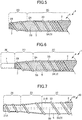
FIG. 5 is a diagram of a distal end portion of a dilator according to a modification. -
FIG. 6 is a diagram of a distal end portion of a dilator according to a modification. -
FIG. 7 is a diagram of a distal end portion of a dilator according to a modification. - Hereinafter, embodiments of the present invention will be described with reference to the drawings. Note that the dimensions of the dilator shown in the drawings are dimensions shown for the purpose of facilitating an understanding of the implementation details, and do not correspond to the actual dimensions.
-
FIG. 1 is an overall view of adilator 1 according to an embodiment of the present invention.FIG. 2 is a cross-sectional view of the vicinity of a boundary between atapered portion 2D and aproximal end portion 2C of thedilator 1 according to the present embodiment. - Furthermore, in
FIG. 1 and FIG. 2 , the left side of the drawing is the distal end side (distal side) inserted into the body, and the right side is the proximal end side (hand side, proximal side) operated by an operator such as a physician. - In
FIG. 1 , thedilator 1 comprises: amultilayered body 4 configured by afirst coil 2 formed by winding one or more metal wires into a hollow shape, and asecond coil 3 formed by winding a single metal wire around an outerperipheral surface 2A of thefirst coil 2 in the opposite direction (Z-twisted) to the first coil 2 (S-twisted); acovering layer 5 that covers the outerperipheral surface 2A of thefirst coil 2; and ahollow connector 6 connected to the proximal end of themultilayered body 4. Note that thesecond coil 3 may be configured by a plurality of metal wires. - The wires constituting the
first coil 2 and thesecond coil 3 are, for example, metal wires made of stainless steel or a superelastic alloy such as nickel-titanium, or are resin wires. - The
first coil 2 is formed, for example, by winding ten metal wires made of stainless steel. Thefirst coil 2 has a hollow shape, and is formed having alumen 2B that passes through from the proximal end to the distal end. Thefirst coil 2 includes aproximal end portion 2C, atapered portion 2D, and adistal end portion 2E. Thefirst coil 2 corresponds to a hollow shaft. - The
proximal end portion 2C is located on the proximal end side of thedilator 1, and aconnector 6 is connected to the proximal end thereof. Furthermore, theproximal end portion 2C has a substantially constant outer diameter from the proximal end to the distal end. - The
tapered portion 2D is located on the distal end side of theproximal end portion 2C, extends from the distal end of theproximal end portion 2C toward the distal end side, and has an outer diameter that decreases toward the distal end side. - The
distal end portion 2E is located on the distal end side of thetapered portion 2D, and extends from the distal end of thetapered portion 2D toward the distal end side. Thedistal end portion 2E has a substantially constant outer diameter from the proximal end to the distal end thereof. In this way, the outer diameter of thefirst coil 2, which is a hollow shaft, increases from the distal end toward the proximal end. - The
second coil 3 is, for example, a single metal wire which is wound around the outerperipheral surface 2A of thefirst coil 2 in the opposite direction (Z-twisted) to the first coil 2 (S-twisted). Here, although the pitch of the metal wire is not particularly limited, the proximal end side represents a close winding in which a part of the metal wire are in contact with each other. The distal end side of theproximal end portion 2C, thetapered portion 2D, and thedistal end portion 2E represent a sparse winding in which parts of the metal wire are separated from each other. As a result of the part of thesecond coil 3 that are wound with a gap (a sparsely wound part), aprotruding portion 3A is formed that makes direct contact with the outerperipheral surface 2A of thefirst coil 2, and which extends in a spiral on the outer periphery of thefirst coil 2 along a lengthwise axis direction of thefirst coil 2. Theprotruding portion 3A hasgaps 3B between adjacent parts of theprotruding portion 3A (between adjacent parts of the metal wire) along the lengthwise axis direction of thefirst coil 2. Thedilator 1 can also be advanced by a rotation operation thedilator 1 as a result of a screw action of the protrudingportion 3A. -
FIG. 2 is a cross-sectional view of the vicinity of a boundary between thetapered portion 2D and theproximal end portion 2C of thedilator 1. - The covering
layer 5 is made of resin, and as shown inFIG. 2 , covers the outerperipheral surface 2A of thefirst coil 2, which is located in thegaps 3B. That is to say, the coveringlayer 5 is located between adjacent parts of theprotruding portion 3A, makes contact with an outerperipheral surface 3C of theprotruding portion 3A, and covers the outerperipheral surface 3C of theprotruding portion 3A. Atop portion 3D of the protrudingportion 3A is exposed to the outside from thecovering layer 5. Thetop portion 3D is exposed to the outside from thecovering layer 5, for example, by covering the entire periphery of theprotruding portion 3A, including thetop portion 3D, with resin, and then peeling off the resin near thetop portion 3D. Examples of the resin constituting the coveringlayer 5 include biocompatible resin materials such as polyamide resins and fluororesins, and hydrophilic coating materials, and the thickness is, for example, 0.1 to 300 µm. - The length of the dilator in the present embodiment and the other embodiments described below is, for example, 2,000 mm, and preferably 1,600 mm to 2,500 mm; the length of the
distal end portion 2E is, for example, 10 mm, and preferably 0 to 100 mm; and further, the length of thetapered portion 2D is, for example, 30 mm, and preferably 5 to 100 mm. The inner diameter at the distal end of thefirst coil 2 is, for example, 0.7 mm, and preferably 0.4 to 1.0 mm; and the inner diameter at the proximal end of thefirst coil 2 is, for example, 1.5 mm, and preferably 1.0 to 3.0 mm. The outer diameter at the distal end of thesecond coil 3 is, for example, 1.84 mm, and preferably 0.8 to 3.0 mm; and the outer diameter at the proximal end of thesecond coil 3 is, for example, 2.64 mm, and preferably 1.4 to 5.0 mm. Furthermore, the diameter of the metal wires of thefirst coil 2 is, for example, 0.21 mm, and preferably 0.1 to 0.5 mm; and the diameter of the metal wire of thesecond coil 3 is, for example, 0.36 mm, and preferably 0.1 to 0.5 mm. - The
connector 6, which is a grip portion, is a portion that an operator uses to push the dilator into the body, or to perform a rotation operation. The distal end of theconnector 6 is connected to the proximal end of thefirst coil 2 and the proximal end of thesecond coil 3. Theconnector 6 is made of resin, and has a hollow shape having a lumen which communicates with thelumen 2B of thefirst coil 2. - The
dilator 1 of the present embodiment is provided with thecovering layer 5, which covers the outerperipheral surface 2A of thefirst coil 2 located in thegaps 3B; therefore, it is possible to suppress displacement, in the lengthwise axis direction, of the protrudingportion 3A that extends in a spiral. Furthermore, because thecovering layer 5 is located between adjacent parts of the protrudingportion 3A, and makes contact with the outerperipheral surface 3C of the protrudingportion 3A, it is possible to suppress displacement of the protrudingportion 3A in the lengthwise axis direction even further. Thecovering layer 5 enables the sliding properties of thedilator 1 to be improved, and thefirst coil 2 is capable of preventing pinching of the living tissue. Because thetop portion 3D of the protrudingportion 3A is exposed, compared to a case where thetop portion 3D is covered by thecovering layer 5, it is possible to improve the resistance to the abrasion that occurs with respect to the living tissue and the like at the time of rotation of thedilator 1. - Next, an example of the dilator when in use will be described.
- First, a target object is punctured with an introduction needle to form a hole. Then, after inserting a guide wire into a lumen of the introduction needle, the introduction needle is removed.
- Next, the proximal end of the guide wire is inserted into the lumen of the dilator, and the dilator is inserted. Then, the dilator is pushed forward while rotating the shaft to expand the hole of the punctured portion. At this time, the tapered portion advances due to a screw action or the like of the spirally-arranged protruding portion due to the rotation operation of the shaft, and the hole can be smoothly expanded by the tapered portion.
- Although embodiments of the present invention have been described above, the present invention is not limited to these embodiments, and various modifications can be made.
- For example, as shown in
FIG. 3 , thecovering layer 5 may cover the entire periphery of the outerperipheral surface 2A of thefirst coil 2, and the protrudingportion 3A (second coil 3) may be provided on thecovering layer 5. Specifically, the protrudingportion 3A (second coil 3) is wound around thecovering layer 5 while pressing thecovering layer 5 toward the inner radial direction of thefirst coil 2 with the protrudingportion 3A (second coil 3). As a result, a concave portion is formed on thecovering layer 5 along the protrudingportion 3A (second coil 3). Further, the structure becomes one in which the protrudingportion 3A (second coil 3) is fitted into the concave portion. According to this configuration, because thecovering layer 5 is located between adjacent parts of the protrudingportion 3A, and makes contact with the outerperipheral surface 3C of the protrudingportion 3A, it is possible to suppress displacement of the protrudingportion 3A in the lengthwise axis direction, and to prevent pinching of the living tissue. - Furthermore, as shown in
FIG. 4 , thedilator 1 of the embodiment may be adilator 10 in which thesecond coil 3 has gaps between adjacent parts along the axial direction of thefirst coil 3 up to the proximal end thereof. - Moreover, as shown in
FIG. 5 , thefirst coil 2, which is a hollow shaft, does not have to have adistal end portion 2E, or as shown inFIG. 6 , may have an approximately cylindrical and hollow leading-edge portion 7, which is formed by pouring a brazing material (a silver-tin brazing material, a gold-tin brazing material, or the like) into thedistal end portion 2E of thefirst coil 2. In addition, a distal tip having the same shape as the leading-edge portion 7 may be provided on the distal end side of the taperedportion 2D instead of thedistal end portion 2E (leading-edge portion 7). Also, the resin of theresin layer 5 may be provided in excess on thedistal end portion 2E or on the distal end side of the taperedportion 2D, and a distal tip made of resin may be formed on the distal end side by the resin that has been provided in excess. Furthermore, a tip may be formed on thedistal end portion 2E or on the distal end side of the taperedportion 2D using the resin of theresin layer 5 and a meltable resin material. - In addition, as shown in
FIG. 7 , adilator 20 is also possible in which thefirst coil 2 is constituted by ahollow shaft 21 formed by casting or the like. Thehollow shaft 21 has a hollow shape, and is formed having alumen 21A that passes through from the proximal end to the distal end. Furthermore, thehollow shaft 21 includes aproximal end portion 22, a taperedportion 23, and adistal end portion 24, and the outer diameter increases from the distal end toward the proximal end. The material forming thehollow shaft 21 is not particularly limited as long as it ensures the softness of the taperedportion 23 and thedistal end portion 24, and is biocompatible, and examples include stainless steel, superelastic alloy materials such as nickel-titanium alloy, and synthetic resins such as polyvinyl chloride resins, urethane resins, polyolefin resins, polyamide resins, and fluorine resins. - Further, the
second coil 3 is wound around the outerperipheral surface 21B of thehollow shaft 21 in the same manner as in the embodiment above. That is to say, thesecond coil 3 is provided making direct contact with the outerperipheral surface 21B of thehollow shaft 21. Thecovering layer 5 covers the outerperipheral surface 21B of thehollow shaft 21, which is located in thegaps 3B of adjacent parts of the protrudingportion 3A. That is to say, thecovering layer 5 is located between adjacent parts of the protrudingportion 3A, makes contact with the outerperipheral surface 3C of the protrudingportion 3A, and covers the outerperipheral surface 3C of the protrudingportion 3A. Thetop portion 3D of the protrudingportion 3A is exposed to the outside from thecovering layer 5. - The
covering layer 5 may cover the entire periphery of the outerperipheral surface 21B of thehollow shaft 21, and the protrudingportion 3A (second coil 3) may be provided on thecovering layer 5. Specifically, the protrudingportion 3A (second coil 3) is wound around thecovering layer 5 while pressing thecovering layer 5 toward the inner radial direction of thehollow shaft 21 with the protrudingportion 3A (second coil 3). As a result, a concave portion is formed on thecovering layer 5 along the protrudingportion 3A (second coil 3). Further, the structure becomes one in which the protrudingportion 3A (second coil 3) is fitted into the concave portion. According to this configuration, because thecovering layer 5 is located between adjacent parts of the protrudingportion 3A, and makes contact with the outerperipheral surface 3C of the protrudingportion 3A, it is possible to suppress displacement of the protrudingportion 3A in the lengthwise axis direction, and to prevent pinching of the living tissue. - The
dilator 20 is also provided with thecovering layer 5, which covers the outerperipheral surface 2A of thesecond coil 2 located in thegaps 3B; therefore, it is possible to suppress displacement, in the lengthwise axis direction, of the protrudingportion 3A that extends in a spiral. Because thecovering layer 5 is located between adjacent parts of the protrudingportion 3A, and makes contact with the outerperipheral surface 3C of the protrudingportion 3A, it is possible to suppress displacement of the protrudingportion 3A in the lengthwise axis direction even further. Because thetop portion 3D of the protrudingportion 3A is exposed, compared to a case where thetop portion 3D is covered by thecovering layer 5, it is possible to improve the resistance to the abrasion that occurs with respect to the living tissue and the like at the time of rotation of thedilator 1. - Furthermore, the outer peripheral surface of the
second coil 3, which is closely wound on the proximal end side of thefirst coil 2 orhollow shaft 21, may also be covered by a resin. - Moreover, in the embodiments above, although the
first coil 2 was described as a hollow coil body formed from ten wires, the number of wires is not limited to ten, and may be one or more. - In the embodiment shown in
FIG. 7 , the surface of the hollow shaft 21 (including the portion between the shaft and the spirally-arranged protruding portion) may have various coatings. Examples of the coating include a protective film (a typical example being a plating film) on the surface of thehollow shaft 21, and a base film for improving the adhesion between thehollow shaft 21 and thesecond coil 3. - In the embodiments shown in
FIG. 1 to FIG. 7 , the spirally-arranged protruding portion preferably does not constitute a blade. The dilators of the present embodiments expand a pre-formed hole in a target object (an example being the wall of a digestive tract such as a patient's stomach). Therefore, if the spirally-arranged protruding portion constitutes a blade, the living tissue on the inner surface of the hole becomes damaged. - Therefore, the cross-sectional shape of the spirally-arranged protruding portion (for example, the shape of the cross-section taken orthogonally to the spiral direction of the spirally-arranged protruding
portion 3A shown inFIG. 2 ) preferably does not have a corner portion having an acute angle on the radially outer end portion of the shaft. That is to say, the end portion preferably has a portion which is formed having, for example, a shape which contains a corner portion having an obtuse angle, or a curve (for example, a curve containing part of a circle or an ellipse). -
- 1, 10, 20 Dilator
- 2 First coil
- 2A Outer peripheral surface
- 3 Second coil
- 3A Protruding portion
- 3B Gap
- 3D Top portion
- 5 Covering layer
- 21 Hollow shaft
Claims (4)
- A dilator comprising:a hollow shaft having an outer diameter that increases from a distal end toward a proximal end; anda protruding portion that is provided on an outer periphery of the hollow shaft, and extends along the outer periphery of the hollow shaft in a spiral along a lengthwise axis direction of the hollow shaft; whereinthe protruding portion has gaps between adjacent parts of the protruding portion along the lengthwise axis direction,a covering layer is provided that covers at least an outer peripheral surface of the hollow shaft, said outer peripheral surface being located in the gaps, anda top portion of the protruding portion is exposed.
- The dilator according to claim 1, wherein
the protruding portion is provided so as to make contact with the outer peripheral surface of the hollow shaft, and
the covering layer is located between adjacent parts of the protruding portion, and makes contact with an outer peripheral surface of the protruding portion. - The dilator according to claim 1, wherein
the covering layer covers the outer peripheral surface of the hollow shaft, and
the protruding portion is provided on the covering layer. - A dilator according to any one of claims 1 to 3, wherein
the hollow shaft comprises a first coil, in which one or more wires are wound into a hollow shape, and
the protruding portion comprises a second coil, in which one or more wires are wound around the outer peripheral surface of the hollow shaft.
Applications Claiming Priority (1)
| Application Number | Priority Date | Filing Date | Title |
|---|---|---|---|
| PCT/JP2018/035091 WO2020059121A1 (en) | 2018-09-21 | 2018-09-21 | Dilator |
Publications (3)
| Publication Number | Publication Date |
|---|---|
| EP3854327A1 true EP3854327A1 (en) | 2021-07-28 |
| EP3854327A4 EP3854327A4 (en) | 2022-04-06 |
| EP3854327B1 EP3854327B1 (en) | 2024-01-10 |
Family
ID=69888781
Family Applications (1)
| Application Number | Title | Priority Date | Filing Date |
|---|---|---|---|
| EP18934183.7A Active EP3854327B1 (en) | 2018-09-21 | 2018-09-21 | Dilator |
Country Status (5)
| Country | Link |
|---|---|
| US (1) | US20210186559A1 (en) |
| EP (1) | EP3854327B1 (en) |
| JP (1) | JP7036936B2 (en) |
| CN (1) | CN112702963B (en) |
| WO (1) | WO2020059121A1 (en) |
Families Citing this family (7)
| Publication number | Priority date | Publication date | Assignee | Title |
|---|---|---|---|---|
| JP7330129B2 (en) * | 2020-04-03 | 2023-08-21 | 朝日インテック株式会社 | dilator |
| WO2022049688A1 (en) * | 2020-09-03 | 2022-03-10 | 朝日インテック株式会社 | Dilator |
| JP2024058939A (en) * | 2022-10-17 | 2024-04-30 | 朝日インテック株式会社 | Medical device, coating method |
| JP2024104068A (en) * | 2023-01-23 | 2024-08-02 | 朝日インテック株式会社 | Medical Devices |
| JPWO2024166254A1 (en) * | 2023-02-08 | 2024-08-15 | ||
| USD1095831S1 (en) * | 2023-04-07 | 2025-09-30 | Asahi Intecc Co., Ltd. | Medical dilator |
| CN121794014A (en) * | 2023-09-22 | 2026-04-03 | 朝日英达科株式会社 | Medical device |
Family Cites Families (21)
| Publication number | Priority date | Publication date | Assignee | Title |
|---|---|---|---|---|
| US207932A (en) * | 1878-09-10 | Improvement in surgical dilators | ||
| CA1318469C (en) * | 1989-02-15 | 1993-06-01 | Acromed Corporation | Artificial disc |
| DE69207844T2 (en) * | 1991-08-07 | 1996-06-27 | Cook Inc | Surgical insertion sleeve |
| DE4312147C2 (en) * | 1992-04-14 | 1996-01-25 | Olympus Optical Co | Trocar |
| AU778076B2 (en) * | 1999-09-17 | 2004-11-11 | Tyco Healthcare Group Lp | Mechanical pump for removal of fragmented matter and methods of manufacture and use |
| CA2397697C (en) | 2000-01-28 | 2008-04-15 | William Cook, Europe Aps | Endovascular medical device with plurality of wires |
| JP3915862B2 (en) | 2000-02-09 | 2007-05-16 | テルモ株式会社 | catheter |
| EP1203594B1 (en) | 2000-11-03 | 2005-11-30 | Willy Rüsch GmbH | Tracheostomy dilator |
| JP4497454B2 (en) * | 2004-04-06 | 2010-07-07 | 朝日インテック株式会社 | Medical tools |
| US8500628B2 (en) * | 2006-02-28 | 2013-08-06 | Olympus Endo Technology America, Inc. | Rotate-to-advance catheterization system |
| US20090281500A1 (en) * | 2006-04-19 | 2009-11-12 | Acosta Pablo G | Devices, system and methods for minimally invasive abdominal surgical procedures |
| US20090281386A1 (en) * | 2006-04-19 | 2009-11-12 | Acosta Pablo G | Devices, system and methods for minimally invasive abdominal surgical procedures |
| JP2008011867A (en) | 2006-05-25 | 2008-01-24 | Nippon Zeon Co Ltd | Dilator, dilator manufacturing method, and sheath introducer |
| US20080161927A1 (en) * | 2006-10-18 | 2008-07-03 | Warsaw Orthopedic, Inc. | Intervertebral Implant with Porous Portions |
| JP5189801B2 (en) * | 2007-07-13 | 2013-04-24 | 富士フイルム株式会社 | Coil winding device for flexible tube |
| US8795326B2 (en) * | 2007-10-05 | 2014-08-05 | Covidien Lp | Expanding seal anchor for single incision surgery |
| US7857789B2 (en) * | 2009-03-10 | 2010-12-28 | Tyco Healthcare Group Lp | Port fixation using expandable threads |
| US8137267B2 (en) * | 2009-04-08 | 2012-03-20 | Ethicon Endo-Surgery, Inc. | Retractor with flexible sleeve |
| JP5736735B2 (en) * | 2010-11-09 | 2015-06-17 | 住友ベークライト株式会社 | catheter |
| US20140046357A1 (en) | 2012-08-09 | 2014-02-13 | Cook Medical Technologies Llc | Dilation device |
| WO2018180209A1 (en) * | 2017-03-28 | 2018-10-04 | テルモ株式会社 | Medical device |
-
2018
- 2018-09-21 CN CN201880097701.8A patent/CN112702963B/en active Active
- 2018-09-21 JP JP2020547580A patent/JP7036936B2/en active Active
- 2018-09-21 EP EP18934183.7A patent/EP3854327B1/en active Active
- 2018-09-21 WO PCT/JP2018/035091 patent/WO2020059121A1/en not_active Ceased
-
2021
- 2021-03-05 US US17/193,640 patent/US20210186559A1/en not_active Abandoned
Also Published As
| Publication number | Publication date |
|---|---|
| US20210186559A1 (en) | 2021-06-24 |
| EP3854327B1 (en) | 2024-01-10 |
| WO2020059121A1 (en) | 2020-03-26 |
| CN112702963B (en) | 2025-01-03 |
| JPWO2020059121A1 (en) | 2021-08-30 |
| JP7036936B2 (en) | 2022-03-15 |
| EP3854327A4 (en) | 2022-04-06 |
| CN112702963A (en) | 2021-04-23 |
Similar Documents
| Publication | Publication Date | Title |
|---|---|---|
| EP3854327B1 (en) | Dilator | |
| US12453843B2 (en) | Dilator | |
| EP3804641A1 (en) | Dilator | |
| CN112714634B (en) | Dilator | |
| EP4209187B1 (en) | Dilator | |
| JP6588679B1 (en) | Dilator |
Legal Events
| Date | Code | Title | Description |
|---|---|---|---|
| STAA | Information on the status of an ep patent application or granted ep patent |
Free format text: STATUS: THE INTERNATIONAL PUBLICATION HAS BEEN MADE |
|
| PUAI | Public reference made under article 153(3) epc to a published international application that has entered the european phase |
Free format text: ORIGINAL CODE: 0009012 |
|
| STAA | Information on the status of an ep patent application or granted ep patent |
Free format text: STATUS: REQUEST FOR EXAMINATION WAS MADE |
|
| 17P | Request for examination filed |
Effective date: 20210319 |
|
| AK | Designated contracting states |
Kind code of ref document: A1 Designated state(s): AL AT BE BG CH CY CZ DE DK EE ES FI FR GB GR HR HU IE IS IT LI LT LU LV MC MK MT NL NO PL PT RO RS SE SI SK SM TR |
|
| DAV | Request for validation of the european patent (deleted) | ||
| DAX | Request for extension of the european patent (deleted) | ||
| A4 | Supplementary search report drawn up and despatched |
Effective date: 20220307 |
|
| RIC1 | Information provided on ipc code assigned before grant |
Ipc: A61M 25/00 20060101ALN20220301BHEP Ipc: A61M 29/00 20060101ALI20220301BHEP Ipc: A61M 25/06 20060101ALI20220301BHEP Ipc: A61B 17/34 20060101AFI20220301BHEP |
|
| GRAP | Despatch of communication of intention to grant a patent |
Free format text: ORIGINAL CODE: EPIDOSNIGR1 |
|
| STAA | Information on the status of an ep patent application or granted ep patent |
Free format text: STATUS: GRANT OF PATENT IS INTENDED |
|
| RIC1 | Information provided on ipc code assigned before grant |
Ipc: A61M 25/00 20060101ALN20230710BHEP Ipc: A61M 29/00 20060101ALI20230710BHEP Ipc: A61M 25/06 20060101ALI20230710BHEP Ipc: A61B 17/34 20060101AFI20230710BHEP |
|
| INTG | Intention to grant announced |
Effective date: 20230725 |
|
| RIN1 | Information on inventor provided before grant (corrected) |
Inventor name: YAGI, MASARU Inventor name: FUSEYA, YUKIHIRO |
|
| GRAS | Grant fee paid |
Free format text: ORIGINAL CODE: EPIDOSNIGR3 |
|
| GRAA | (expected) grant |
Free format text: ORIGINAL CODE: 0009210 |
|
| STAA | Information on the status of an ep patent application or granted ep patent |
Free format text: STATUS: THE PATENT HAS BEEN GRANTED |
|
| AK | Designated contracting states |
Kind code of ref document: B1 Designated state(s): AL AT BE BG CH CY CZ DE DK EE ES FI FR GB GR HR HU IE IS IT LI LT LU LV MC MK MT NL NO PL PT RO RS SE SI SK SM TR |
|
| REG | Reference to a national code |
Ref country code: GB Ref legal event code: FG4D |
|
| REG | Reference to a national code |
Ref country code: CH Ref legal event code: EP |
|
| REG | Reference to a national code |
Ref country code: DE Ref legal event code: R096 Ref document number: 602018064150 Country of ref document: DE |
|
| REG | Reference to a national code |
Ref country code: IE Ref legal event code: FG4D |
|
| REG | Reference to a national code |
Ref country code: LT Ref legal event code: MG9D |
|
| REG | Reference to a national code |
Ref country code: NL Ref legal event code: MP Effective date: 20240110 |
|
| REG | Reference to a national code |
Ref country code: AT Ref legal event code: MK05 Ref document number: 1648281 Country of ref document: AT Kind code of ref document: T Effective date: 20240110 |
|
| PG25 | Lapsed in a contracting state [announced via postgrant information from national office to epo] |
Ref country code: NL Free format text: LAPSE BECAUSE OF FAILURE TO SUBMIT A TRANSLATION OF THE DESCRIPTION OR TO PAY THE FEE WITHIN THE PRESCRIBED TIME-LIMIT Effective date: 20240110 |
|
| PG25 | Lapsed in a contracting state [announced via postgrant information from national office to epo] |
Ref country code: NL Free format text: LAPSE BECAUSE OF FAILURE TO SUBMIT A TRANSLATION OF THE DESCRIPTION OR TO PAY THE FEE WITHIN THE PRESCRIBED TIME-LIMIT Effective date: 20240110 |
|
| PG25 | Lapsed in a contracting state [announced via postgrant information from national office to epo] |
Ref country code: IS Free format text: LAPSE BECAUSE OF FAILURE TO SUBMIT A TRANSLATION OF THE DESCRIPTION OR TO PAY THE FEE WITHIN THE PRESCRIBED TIME-LIMIT Effective date: 20240510 |
|
| PG25 | Lapsed in a contracting state [announced via postgrant information from national office to epo] |
Ref country code: LT Free format text: LAPSE BECAUSE OF FAILURE TO SUBMIT A TRANSLATION OF THE DESCRIPTION OR TO PAY THE FEE WITHIN THE PRESCRIBED TIME-LIMIT Effective date: 20240110 |
|
| PG25 | Lapsed in a contracting state [announced via postgrant information from national office to epo] |
Ref country code: GR Free format text: LAPSE BECAUSE OF FAILURE TO SUBMIT A TRANSLATION OF THE DESCRIPTION OR TO PAY THE FEE WITHIN THE PRESCRIBED TIME-LIMIT Effective date: 20240411 |
|
| PG25 | Lapsed in a contracting state [announced via postgrant information from national office to epo] |
Ref country code: HR Free format text: LAPSE BECAUSE OF FAILURE TO SUBMIT A TRANSLATION OF THE DESCRIPTION OR TO PAY THE FEE WITHIN THE PRESCRIBED TIME-LIMIT Effective date: 20240110 Ref country code: RS Free format text: LAPSE BECAUSE OF FAILURE TO SUBMIT A TRANSLATION OF THE DESCRIPTION OR TO PAY THE FEE WITHIN THE PRESCRIBED TIME-LIMIT Effective date: 20240410 |
|
| PG25 | Lapsed in a contracting state [announced via postgrant information from national office to epo] |
Ref country code: ES Free format text: LAPSE BECAUSE OF FAILURE TO SUBMIT A TRANSLATION OF THE DESCRIPTION OR TO PAY THE FEE WITHIN THE PRESCRIBED TIME-LIMIT Effective date: 20240110 |
|
| PG25 | Lapsed in a contracting state [announced via postgrant information from national office to epo] |
Ref country code: AT Free format text: LAPSE BECAUSE OF FAILURE TO SUBMIT A TRANSLATION OF THE DESCRIPTION OR TO PAY THE FEE WITHIN THE PRESCRIBED TIME-LIMIT Effective date: 20240110 |
|
| PG25 | Lapsed in a contracting state [announced via postgrant information from national office to epo] |
Ref country code: RS Free format text: LAPSE BECAUSE OF FAILURE TO SUBMIT A TRANSLATION OF THE DESCRIPTION OR TO PAY THE FEE WITHIN THE PRESCRIBED TIME-LIMIT Effective date: 20240410 Ref country code: NO Free format text: LAPSE BECAUSE OF FAILURE TO SUBMIT A TRANSLATION OF THE DESCRIPTION OR TO PAY THE FEE WITHIN THE PRESCRIBED TIME-LIMIT Effective date: 20240410 Ref country code: LT Free format text: LAPSE BECAUSE OF FAILURE TO SUBMIT A TRANSLATION OF THE DESCRIPTION OR TO PAY THE FEE WITHIN THE PRESCRIBED TIME-LIMIT Effective date: 20240110 Ref country code: IS Free format text: LAPSE BECAUSE OF FAILURE TO SUBMIT A TRANSLATION OF THE DESCRIPTION OR TO PAY THE FEE WITHIN THE PRESCRIBED TIME-LIMIT Effective date: 20240510 Ref country code: HR Free format text: LAPSE BECAUSE OF FAILURE TO SUBMIT A TRANSLATION OF THE DESCRIPTION OR TO PAY THE FEE WITHIN THE PRESCRIBED TIME-LIMIT Effective date: 20240110 Ref country code: GR Free format text: LAPSE BECAUSE OF FAILURE TO SUBMIT A TRANSLATION OF THE DESCRIPTION OR TO PAY THE FEE WITHIN THE PRESCRIBED TIME-LIMIT Effective date: 20240411 Ref country code: ES Free format text: LAPSE BECAUSE OF FAILURE TO SUBMIT A TRANSLATION OF THE DESCRIPTION OR TO PAY THE FEE WITHIN THE PRESCRIBED TIME-LIMIT Effective date: 20240110 Ref country code: BG Free format text: LAPSE BECAUSE OF FAILURE TO SUBMIT A TRANSLATION OF THE DESCRIPTION OR TO PAY THE FEE WITHIN THE PRESCRIBED TIME-LIMIT Effective date: 20240110 Ref country code: AT Free format text: LAPSE BECAUSE OF FAILURE TO SUBMIT A TRANSLATION OF THE DESCRIPTION OR TO PAY THE FEE WITHIN THE PRESCRIBED TIME-LIMIT Effective date: 20240110 |
|
| PG25 | Lapsed in a contracting state [announced via postgrant information from national office to epo] |
Ref country code: PL Free format text: LAPSE BECAUSE OF FAILURE TO SUBMIT A TRANSLATION OF THE DESCRIPTION OR TO PAY THE FEE WITHIN THE PRESCRIBED TIME-LIMIT Effective date: 20240110 Ref country code: PT Free format text: LAPSE BECAUSE OF FAILURE TO SUBMIT A TRANSLATION OF THE DESCRIPTION OR TO PAY THE FEE WITHIN THE PRESCRIBED TIME-LIMIT Effective date: 20240510 |
|
| PG25 | Lapsed in a contracting state [announced via postgrant information from national office to epo] |
Ref country code: SE Free format text: LAPSE BECAUSE OF FAILURE TO SUBMIT A TRANSLATION OF THE DESCRIPTION OR TO PAY THE FEE WITHIN THE PRESCRIBED TIME-LIMIT Effective date: 20240110 Ref country code: PT Free format text: LAPSE BECAUSE OF FAILURE TO SUBMIT A TRANSLATION OF THE DESCRIPTION OR TO PAY THE FEE WITHIN THE PRESCRIBED TIME-LIMIT Effective date: 20240510 Ref country code: PL Free format text: LAPSE BECAUSE OF FAILURE TO SUBMIT A TRANSLATION OF THE DESCRIPTION OR TO PAY THE FEE WITHIN THE PRESCRIBED TIME-LIMIT Effective date: 20240110 Ref country code: LV Free format text: LAPSE BECAUSE OF FAILURE TO SUBMIT A TRANSLATION OF THE DESCRIPTION OR TO PAY THE FEE WITHIN THE PRESCRIBED TIME-LIMIT Effective date: 20240110 |
|
| PG25 | Lapsed in a contracting state [announced via postgrant information from national office to epo] |
Ref country code: DK Free format text: LAPSE BECAUSE OF FAILURE TO SUBMIT A TRANSLATION OF THE DESCRIPTION OR TO PAY THE FEE WITHIN THE PRESCRIBED TIME-LIMIT Effective date: 20240110 |
|
| REG | Reference to a national code |
Ref country code: DE Ref legal event code: R097 Ref document number: 602018064150 Country of ref document: DE |
|
| PG25 | Lapsed in a contracting state [announced via postgrant information from national office to epo] |
Ref country code: SM Free format text: LAPSE BECAUSE OF FAILURE TO SUBMIT A TRANSLATION OF THE DESCRIPTION OR TO PAY THE FEE WITHIN THE PRESCRIBED TIME-LIMIT Effective date: 20240110 |
|
| PG25 | Lapsed in a contracting state [announced via postgrant information from national office to epo] |
Ref country code: EE Free format text: LAPSE BECAUSE OF FAILURE TO SUBMIT A TRANSLATION OF THE DESCRIPTION OR TO PAY THE FEE WITHIN THE PRESCRIBED TIME-LIMIT Effective date: 20240110 Ref country code: CZ Free format text: LAPSE BECAUSE OF FAILURE TO SUBMIT A TRANSLATION OF THE DESCRIPTION OR TO PAY THE FEE WITHIN THE PRESCRIBED TIME-LIMIT Effective date: 20240110 |
|
| PG25 | Lapsed in a contracting state [announced via postgrant information from national office to epo] |
Ref country code: SK Free format text: LAPSE BECAUSE OF FAILURE TO SUBMIT A TRANSLATION OF THE DESCRIPTION OR TO PAY THE FEE WITHIN THE PRESCRIBED TIME-LIMIT Effective date: 20240110 |
|
| PG25 | Lapsed in a contracting state [announced via postgrant information from national office to epo] |
Ref country code: SM Free format text: LAPSE BECAUSE OF FAILURE TO SUBMIT A TRANSLATION OF THE DESCRIPTION OR TO PAY THE FEE WITHIN THE PRESCRIBED TIME-LIMIT Effective date: 20240110 Ref country code: SK Free format text: LAPSE BECAUSE OF FAILURE TO SUBMIT A TRANSLATION OF THE DESCRIPTION OR TO PAY THE FEE WITHIN THE PRESCRIBED TIME-LIMIT Effective date: 20240110 Ref country code: RO Free format text: LAPSE BECAUSE OF FAILURE TO SUBMIT A TRANSLATION OF THE DESCRIPTION OR TO PAY THE FEE WITHIN THE PRESCRIBED TIME-LIMIT Effective date: 20240110 Ref country code: EE Free format text: LAPSE BECAUSE OF FAILURE TO SUBMIT A TRANSLATION OF THE DESCRIPTION OR TO PAY THE FEE WITHIN THE PRESCRIBED TIME-LIMIT Effective date: 20240110 Ref country code: DK Free format text: LAPSE BECAUSE OF FAILURE TO SUBMIT A TRANSLATION OF THE DESCRIPTION OR TO PAY THE FEE WITHIN THE PRESCRIBED TIME-LIMIT Effective date: 20240110 Ref country code: CZ Free format text: LAPSE BECAUSE OF FAILURE TO SUBMIT A TRANSLATION OF THE DESCRIPTION OR TO PAY THE FEE WITHIN THE PRESCRIBED TIME-LIMIT Effective date: 20240110 |
|
| PLBE | No opposition filed within time limit |
Free format text: ORIGINAL CODE: 0009261 |
|
| STAA | Information on the status of an ep patent application or granted ep patent |
Free format text: STATUS: NO OPPOSITION FILED WITHIN TIME LIMIT |
|
| PG25 | Lapsed in a contracting state [announced via postgrant information from national office to epo] |
Ref country code: IT Free format text: LAPSE BECAUSE OF FAILURE TO SUBMIT A TRANSLATION OF THE DESCRIPTION OR TO PAY THE FEE WITHIN THE PRESCRIBED TIME-LIMIT Effective date: 20240110 |
|
| 26N | No opposition filed |
Effective date: 20241011 |
|
| PG25 | Lapsed in a contracting state [announced via postgrant information from national office to epo] |
Ref country code: IT Free format text: LAPSE BECAUSE OF FAILURE TO SUBMIT A TRANSLATION OF THE DESCRIPTION OR TO PAY THE FEE WITHIN THE PRESCRIBED TIME-LIMIT Effective date: 20240110 |
|
| PG25 | Lapsed in a contracting state [announced via postgrant information from national office to epo] |
Ref country code: MC Free format text: LAPSE BECAUSE OF FAILURE TO SUBMIT A TRANSLATION OF THE DESCRIPTION OR TO PAY THE FEE WITHIN THE PRESCRIBED TIME-LIMIT Effective date: 20240110 Ref country code: SI Free format text: LAPSE BECAUSE OF FAILURE TO SUBMIT A TRANSLATION OF THE DESCRIPTION OR TO PAY THE FEE WITHIN THE PRESCRIBED TIME-LIMIT Effective date: 20240110 |
|
| REG | Reference to a national code |
Ref country code: CH Ref legal event code: PL |
|
| PG25 | Lapsed in a contracting state [announced via postgrant information from national office to epo] |
Ref country code: LU Free format text: LAPSE BECAUSE OF NON-PAYMENT OF DUE FEES Effective date: 20240921 |
|
| REG | Reference to a national code |
Ref country code: BE Ref legal event code: MM Effective date: 20240930 |
|
| PG25 | Lapsed in a contracting state [announced via postgrant information from national office to epo] |
Ref country code: BE Free format text: LAPSE BECAUSE OF NON-PAYMENT OF DUE FEES Effective date: 20240930 |
|
| PG25 | Lapsed in a contracting state [announced via postgrant information from national office to epo] |
Ref country code: CH Free format text: LAPSE BECAUSE OF NON-PAYMENT OF DUE FEES Effective date: 20240930 |
|
| PG25 | Lapsed in a contracting state [announced via postgrant information from national office to epo] |
Ref country code: IE Free format text: LAPSE BECAUSE OF NON-PAYMENT OF DUE FEES Effective date: 20240921 |
|
| PG25 | Lapsed in a contracting state [announced via postgrant information from national office to epo] |
Ref country code: FI Free format text: LAPSE BECAUSE OF FAILURE TO SUBMIT A TRANSLATION OF THE DESCRIPTION OR TO PAY THE FEE WITHIN THE PRESCRIBED TIME-LIMIT Effective date: 20240110 |
|
| PGFP | Annual fee paid to national office [announced via postgrant information from national office to epo] |
Ref country code: DE Payment date: 20250919 Year of fee payment: 8 |
|
| PGFP | Annual fee paid to national office [announced via postgrant information from national office to epo] |
Ref country code: GB Payment date: 20250919 Year of fee payment: 8 |
|
| PGFP | Annual fee paid to national office [announced via postgrant information from national office to epo] |
Ref country code: FR Payment date: 20250922 Year of fee payment: 8 |
|
| PG25 | Lapsed in a contracting state [announced via postgrant information from national office to epo] |
Ref country code: CY Free format text: LAPSE BECAUSE OF FAILURE TO SUBMIT A TRANSLATION OF THE DESCRIPTION OR TO PAY THE FEE WITHIN THE PRESCRIBED TIME-LIMIT; INVALID AB INITIO Effective date: 20180921 |
|
| PG25 | Lapsed in a contracting state [announced via postgrant information from national office to epo] |
Ref country code: HU Free format text: LAPSE BECAUSE OF FAILURE TO SUBMIT A TRANSLATION OF THE DESCRIPTION OR TO PAY THE FEE WITHIN THE PRESCRIBED TIME-LIMIT; INVALID AB INITIO Effective date: 20180921 |