EP3854054B1 - Übertragung elektronischer daten zwischen netzwerken von verschiedenem vertrauensniveau - Google Patents
Übertragung elektronischer daten zwischen netzwerken von verschiedenem vertrauensniveau Download PDFInfo
- Publication number
- EP3854054B1 EP3854054B1 EP19770144.4A EP19770144A EP3854054B1 EP 3854054 B1 EP3854054 B1 EP 3854054B1 EP 19770144 A EP19770144 A EP 19770144A EP 3854054 B1 EP3854054 B1 EP 3854054B1
- Authority
- EP
- European Patent Office
- Prior art keywords
- electronic information
- file
- electrical zone
- verified
- zone
- Prior art date
- Legal status (The legal status is an assumption and is not a legal conclusion. Google has not performed a legal analysis and makes no representation as to the accuracy of the status listed.)
- Active
Links
Images
Classifications
-
- H—ELECTRICITY
- H04—ELECTRIC COMMUNICATION TECHNIQUE
- H04L—TRANSMISSION OF DIGITAL INFORMATION, e.g. TELEGRAPHIC COMMUNICATION
- H04L63/00—Network architectures or network communication protocols for network security
- H04L63/02—Network architectures or network communication protocols for network security for separating internal from external traffic, e.g. firewalls
- H04L63/0209—Architectural arrangements, e.g. perimeter networks or demilitarized zones
-
- G—PHYSICS
- G06—COMPUTING OR CALCULATING; COUNTING
- G06F—ELECTRIC DIGITAL DATA PROCESSING
- G06F16/00—Information retrieval; Database structures therefor; File system structures therefor
- G06F16/10—File systems; File servers
- G06F16/16—File or folder operations, e.g. details of user interfaces specifically adapted to file systems
- G06F16/164—File meta data generation
-
- H—ELECTRICITY
- H04—ELECTRIC COMMUNICATION TECHNIQUE
- H04L—TRANSMISSION OF DIGITAL INFORMATION, e.g. TELEGRAPHIC COMMUNICATION
- H04L63/00—Network architectures or network communication protocols for network security
- H04L63/06—Network architectures or network communication protocols for network security for supporting key management in a packet data network
-
- H—ELECTRICITY
- H04—ELECTRIC COMMUNICATION TECHNIQUE
- H04L—TRANSMISSION OF DIGITAL INFORMATION, e.g. TELEGRAPHIC COMMUNICATION
- H04L63/00—Network architectures or network communication protocols for network security
- H04L63/12—Applying verification of the received information
- H04L63/123—Applying verification of the received information received data contents, e.g. message integrity
-
- H—ELECTRICITY
- H04—ELECTRIC COMMUNICATION TECHNIQUE
- H04L—TRANSMISSION OF DIGITAL INFORMATION, e.g. TELEGRAPHIC COMMUNICATION
- H04L63/00—Network architectures or network communication protocols for network security
- H04L63/14—Network architectures or network communication protocols for network security for detecting or protecting against malicious traffic
- H04L63/1441—Countermeasures against malicious traffic
- H04L63/145—Countermeasures against malicious traffic the attack involving the propagation of malware through the network, e.g. viruses, trojans or worms
Definitions
- the invention is in the field of file assurance, in particular to provide assurance of the safety of files being transferred between networks of different trust from a cyber security perspective.
- file or packet filters to prohibit the passage of malicious files to your network whereby malicious files are blocked after an assessment of the file has been made, for example the filter may limit the forwarding of files of a certain file type, file size or format, for example string type.
- US 2018/0124121 discloses a one way coupling device for the feedback free transmission of data from the first network with high security requirements into a second network with low security requirements, containing a request unit, an eavesdropping unit and a receiving unit, wherein the request unit is formed so as to provide a first communication link within a first communication network to at least one device and moreover to request data from the at least one device and then to transmit the first data via a second communication link on a separate line loop of the request unit, and the eavesdropping unit, which is formed to eavesdrop on data on the separate line loop and to transmit data to a receiving unit which is arranged in the second network.
- WO2018/115359 discloses a unidirectional communications system to allow the sending of alerts and notifications to remote operators while relieving the problem of the protection of secured networks against cyber attacks when the secured network has a need to communicate information from the secured network to a public network.
- the solution is based on the use of a data diode (also known under the name of a network diode) to allow directional transmission of information from the secured network to the public network, which makes a computer attack on the secured network from the public network impossible.
- a commanded data diode no sensitive information can leak from the secured network via the system according to the invention. The transmission of the message is only done after the message to be sent has been cleaned of sensitive information and then encrypted.
- the passage of malicious files enables the monitoring of the type and quantity of attacks and the malicious file can be studied in a controlled setting within your trusted infrastructure and can in fact provide you with the knowledge of how to react to any such attack going forward. Therefore, the ability for approved individuals to access the content of these malicious files can be desirable.
- Providing a product that is retrofittable within an existing hardware and network infrastructure is hugely beneficial to users as it reduces the burden of time and cost relating to installation whilst ensuring the monitoring of the malicious files in a controlled and easily identifiable manner on the trusted network such that the file passed to the trusted network can be assured as being safe.
- files containing a header and file content there is a need to pass data that is streamed as data packets from the lesser trusted network to the trusted network.
- a method of transferring electronic information between a lesser trusted network and a trusted network comprising the following steps:
- the fact the data is always passed from the first electrical zone to the second electrical enables the user to obtain an understanding of whether there has been an attempted cyber attack, and this also permits forensic analysis of the type of cyber attack and offers the ability to identify patterns and improve prevention strategies. Further, this information could be used to warn others of a potential threat.
- Electronic information may be considered to be the 'thing' being conveyed, but this may also encompass electronic data which are the bit and byte values i.e. structured text format, for example the values in CSV array of image files e.g. bmp.
- the electrical zone may comprise an electrical module or processor.
- the verified electronic information may be passed from the second zone along at least one second unidirectional pathway to the third electrical zone.
- the second unidirectional pathway prevents electronic information being pulled from the third zone which is in communication with the trusted network.
- the original electronic information may be transformed into the verified electronic information having a transformed state. Therefore, the original electronic information, for example a file can be converted into a different form.
- the original electronic information in a wrapped form preferably meansthe transformation may be applied to the original electronic information is the wrapping of the original electronic information and occurs in the case where the original electronic information cannot be adequately assured as being safe for the users trusted network.
- the transformed state may be provided by an operation of electronically wrapping the electronic information and is dependent upon the electronic key.
- the second zone may trigger the wrapping function to wrap the file prior to forwarding it on to the third zone.
- the verified electronic information in the transformed state may comprise the original electronic information plus a new header.
- the electronic key may be a symmetric key which is used in the function used to wrap the file having the potentially malicious information/content. It is also envisaged that different electronic key types may be used to identify the type of malicious behaviour of the wrapped file, or at the very least may be used to identify that the file has been wrapped to protect the trusted network from a cyber attack. Alternatively, the key may be used to designate the origin of the file or other desirable characteristics about the wrapped file. The key could be used as a classifier e.g. to indicate which stage of the verification process has failed. In some instances, this may provide useful information as to the cyber threat posed by the original file.
- the first option is a header that comprises a pure key and no other information
- the second option has a header structure comprising the key plus metadata.
- Other header information types include data on time, MAC address of generator, name space and version depending on the version) all of which may be bulked out with random data.
- the original electronic information is checked against a compliance rule which identifies a characteristic for which there is an associated action.
- the key is stored in the new header of the wrapped electronic information and the key is accessible to enable the electronic data is to be unwrapped. Either the key may be accessed by a user at the third electrical zone (or subsequent onwards stage) or the electronic key may be used as an identifier of the type of malicious intent. In an alternative embodiment the key is forwarded prior to receipt of the wrapped verified electronic information.
- the verified electronic information may be passed from the second zone along at least one second unidirectional pathway to the third electrical zone.
- the electronic key may be locally generated, preshared or comprises an index to a directory of preshared keys.
- the original electronic information may be a stream of data comprising data packets. In particular an undetermined number of data packets.
- the original electronic information may be a file.
- An input file is a file received by the device at the first electrical zone.
- the predetermined characteristic (that is verified by the verifier) may comprise at least one predetermined file type.
- file types of the form of structured text e.g. CSV or indeed image files e.g. BMP file may be set as the predetermined characteristic.
- the verifier may verify the file types in parallel and is configured such that only one positive result would be achievable (or of course no positive results). Therefore, the predetermined file types may be mutually exclusive for a good implementation.
- the verified file information in the transformed state may comprise the original file header and payload plus a new file header.
- the electronic key that was used in the generation of the verified file information in the transformed state is inserted into the new file header. Therefore, the key is available to an entity who reads the new file header on receipt of the verified file information in the transformed state.
- the method may further comprise providing a time delay to the original electronic information for example file or stream of data received by the first zone by means of a delay algorithm.
- the time delay may be dependent upon the input file size or packet size of the stream of data.
- the input file may be compared to a predetermined file size limit and in the case that the original file is of a size that exceeds the predetermined file size limit, the original file may be transferred to the second electrical zone and the transformation of the file may be automatically triggered providing a transformed file, for example a wrapped file.
- Files that are below the file size limit may be assured assuming the file characteristics are met. There is therefore provided an assured file size limit. Anything that is above this file size limit is automatically transformed/ converted/ wrapped.
- a "run to failure" approach may be implemented whereby the method runs through the file and as long as the file is valid against some predetermined type the method continues to output the file.
- the forwarding of the file is terminated at the last good assessment point (as a first file stage) with the remaining 'malicious' part of the file being forwarded as a second file stage in the verified file transformed state.
- the header contains sufficient information to indicate that this is a continuation from the first file stage, and that it contains malicious content.
- the predetermined criteria are selected, and transition of the file is allowed until a prohibited criteria (e.g. a particular character) is identified.
- a ⁇ wrapped tail file' is then created. This last example may be of limited application dependent upon the type of structured text that is implemented.
- the original electronic information may be a file, for example an input file.
- the key generator located in the second zone provides a symmetric key to be used with a mathematical wrapping function.
- the mathematical wrapping function being operable as an algorithm implemented through computer code at the second electrical zone.
- the resulting wrapped file is the verified electronic information in the wrapped state.
- the size of the input file may not be a parameter in the wrapping algorithm.
- the verified electronic information in a transformed state may be a wrapped file of file size equating to the size of the file plus the size of a new header.
- the device may further comprise the wrapped file storing the key in the new header of the verified electronic information e.g. file. This enables unwrapping of the file at the third electrical zone (or subsequent zones), or at least identification of the malicious file on presence of the electronic key.
- This insertion of the electronic key in the new header beneficially occurs prior to forwarding the verified electronic information in the transformed state to the third zone.
- the first electrical zone may be separate and distinct from the second and third electrical zone.
- the second and third electrical zone may be located on a common module or processor.
- the device may further comprise the second and third electrical zones being separate and distinct from each other. Whilst it is feasible for the second and third electrical zones to be located on a common module or processor, maximal isolation of the second electrical zone is achieved by separating the second and third electrical zones on respective modules or processors.
- the means for transferring the original electronic information between the first electrical zone and second electrical zone in one direction only may comprise a unidirectional pathway located between the first electrical zone and the second electrical zone. This ensures that electronic information from the second electrical zone, cannot be pulled back to the first electrical zone by malicious electronic information yet to be transformed/converted/wrapped.
- a means for transferring the verified electronic information between the second electrical zone and the third electronic zone in one direction only may comprise at least one second unidirectional pathway located between the second electrical zone and the third electrical zone. This ensures that electronic information from the third electrical zone, cannot be pulled back to the second electrical zone by malicious electronic information yet to be transformed/converted/wrapped.
- the at least one first or second unidirectional pathway may comprise at least one hardware component.
- the hardware component may comprise at least one SerDes pin and/or a unidirectional amplifier.
- the second electrical zone may comprise a mathematical function, for example in the form of a coded algorithm for transforming the original electronic information into verified electronic information in the transformed state.
- the mathematical algorithm may be a wrapping algorithm. The output of the wrapping algorithm is dependent on the electronic key.
- the device may further comprise a delay generator for delaying the input of original electronic information to the first electrical zone.
- the delay generator comprises a delay algorithm.
- the delay generator may calculate the delay of the input file reaching the first electrical zone in dependence upon the file size of the input file received by the first electrical zone.
- the first electrical zone may comprise a memory to buffer the input file which is used to determine whether the original electronic information is greater than a predetermined file size limit of the memory.
- the first electrical zone may be configured to be in communication with the lesser trusted network.
- the third electrical zone may be configured to be in communication with the trusted network.
- the second electrical zone may be configured to receive original electronic information from the first electrical zone and is prohibited from receiving verified electronic information from the third electrical zone.
- the first electrical zone, second electrical zone and third electrical zone may comprise at least one first processor, second processor and third processor respectively.
- the second electrical zone is configured to forward verified electronic information to the third electrical zone and is prohibited from forwarding original electronic information or verified electronic information to the first electrical zone.
- a computational device for transferring electronic information from a lesser trusted network to a trusted network comprising a device as here before described.
- Computational devices may comprise a desktop or laptop computer, tablet, personal digital assistant (PDA), mobile phone, smart watch, hard disc, solid state disc or drive, memory, or other smart or mobile device, or IOT device capable of storing and/ or displaying data or otherwise acting as a data device, or a display device comprising a monitor, projector, screen or the like, capable of storing and/ or displaying data or otherwise acting as a data device are also disclosed, which may individually and/ or collectively comprise a device as outlined above for the user's convenience.
- PDA personal digital assistant
- mobile phone smart watch
- hard disc solid state disc or drive
- memory or other smart or mobile device
- IOT device capable of storing and/ or displaying data or otherwise acting as a data device
- a display device comprising a monitor, projector, screen or the like, capable of storing and/ or displaying data or otherwise acting as a data device are also disclosed, which may individually and/ or collectively comprise a device as outlined above for the user's convenience.
- Unidirectional means only permitting passage of the electronic data or electronic information, for example a file or streamed data in one direction e.g. from the first electrical zone to the second electrical zone. This ensures that any electronic information from the second electrical zone cannot be passed back to the first electrical zone. This provides isolation of secure services on the second electrical zone from the network services on the first electrical zone, whilst allowing for information to be transferred between the first electrical zone and second electrical zone.
- File means a set of bytes of a known length.
- the file comprises a header and a payload.
- the "Original File” means the file received by the first electrical zone.
- Verified file is a file that is assessed to meet a file type specification. This file type specification does not have to comprise a header and a payload.
- Trusted network means a business or other organisation's network that is under the control of a network manager or network administrator and which functions within security parameters to form a security perimeter.
- the trusted network is the destination of the electronic information e.g. file or streamed data.
- Lesser trusted network means a network that is deemed untrusted or of unknown trust which lies outside of the security perimeter of the business or other organisation.
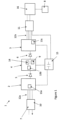
- a device 1 comprising an input module 2, an output module 3 and a security module 4 located between the input module 2 and the output module 3.
- a unidirectional pathway 5 between the input module 2 and the output module 3 so as to enable passage of a file between the input module 2 and the security module 4.
- a second unidirectional pathway 6 located between the security module 4 and the output module 3 so as to permit the transfer of a file from the security module 4 and the output module 3.
- the input module 2 is in communication with an external network (which is considered to be a lesser trusted network 7, for example the internet) and the output module 3 is in communication with a trusted network 8 (for example an internal network of a company).
- the main objective is for all files received by the input module 2 to be successfully forwarded to the output module 3, via the security module 4. Therefore, there will be an output from the output module 3 for every file that is received by the input module 2, as such this method does not offer the conventional filtration capability of the prior art.
- the original file is assessed in the security module 4 by verifying against formats that can be expressed and assessed, for example in an algorithm of state machine form, whereby the user choses to verify all data against one or more data serialisation languages such as CSV, or bitmap (BMP) file types.
- the results of the verification process then determine the format of the file to be forwarded towards the output module 3.
- the file is forwarded onwards to the output module 3 in its original form.
- the security module 4 triggers a wrapping function (not shown) to wrap the file prior to forwarding it on to the output module 3. Therefore, the file is transformed from the original file type to a wrapped file type and can be considered to be a transformed file.
- the device 1 By wrapping the file, the device 1 will have changed the format of the file with the effect that any onward component will no longer be able to inadvertently execute (render) the file.
- the new wrapped file is therefore no longer malicious.
- the non-deterministic nature of the file means that the wrapped file is effectively immune to malicious attacks that try to craft a file that, when wrapped, is itself malicious.
- the user may have made the original electronic information inoperable and any network or onward recipient can be configured to handle the data without vulnerability of attack.
- the first unidirectional pathway 5 and second unidirectional pathway 6 is a hardware component.
- One or more SerDes pins or unidirectional amplifiers are configured to provide connections between the modules.
- the first unidirectional pathway 5 and second unidirectional pathway 6 provides the restriction that the file can be passed in one direction only and this is key to the information assurance of the device 1.
- SerDes pins can only function in one direction, input or output, as designated by the underlying silicon.
- the direction of such pins is not defined by any processing means configuration image; thus, their use provides assurance of one-way transfer, with it being possible to connect only the forward path physically to, or on, a PCB or substrate, which can be visually inspected.
- the objective of the first unidirectional pathway 5 is to ensure isolation of the electronic information contained in the security module 4 from the input (first) module 2.
- the data stored on the security (second) module 4 cannot be pulled to the input module by an unauthorised individual.
- Using a combination of the at least one SerDes pin and a unidirectional amplifier for the unidirectional hardware ensures that more than one failure must occur for the device to be compromised. Therefore, once again this provides an extra layer of assurance that the device is working securely and that there is no leakage of unwanted data between the security module and the input module.
- the high reverse isolation property of the amplifier ensures that any variation in the output is not mirrored in the input i.e. it improves the isolation characteristic between the most trusted interface and the other (lesser-trusted) interface.
- the unidirectional amplifier (not shown) comprises a unity gain amplifier having high reverse isolation characteristics which ensures one-way data travel is provided should any of the termination sensing circuit associated with the SerDes be used as a return path.
- a first and second SerDes pin is configured with a unidirectional amplifier positioned there-between (not shown). Therefore, the unidirectional amplifier is positioned in series with the first SerDes pin and similarly the unidirectional amplifier is positioned in series with the second SerDes pin.
- the device 1 uses a transceiving means for a network connection.
- the transceiving means comprises a receiving means 10 and a transmitting means 11.
- Both the receiving means 10 and the transmitting means 11 comprise an ethernet interface, for example known 8P8C (commonly referred to as the RJ45 connection) which is convenient for the user as it is a common and robust interface type.
- 8P8C commonly referred to as the RJ45 connection
- the device 1 is retrofittable and can be included prior to permitting data to be used, for example, in a specific process, on their network, or by a specific node.
- the input module 2, security module 4 and output module 3 comprise a processing means in the form of a Field Programmable Gate Array (FPGA).
- FPGA Field Programmable Gate Array
- a file is received by the receiving means 10 located in communication with the input module 2 and travels notionally from left to right through the file transfer device 1 to the transmitting means 11 located in communication with the output module 3.
- An interconnection 12a between the receiving means 10 and the input module 2 as well as an interconnection 12b between the output module 3 and the transmitting means 11 comprise bi-directional data flow to support standard layer 2 and layer 3 signalling.
- Each module comprises memory 13a, 13b, 13c in the form of SDRAM to support buffering of the file.
- the file is received by the buffer.
- the file size is compared to a predetermined size limit x provided by the memory.
- the file size is at or below the file size limit x, it will be held in the buffer, clocked and then forwarded to the security module 4.
- the file will be forwarded to the security module 4 regardless of whether the file limit has been exceeded, however if the file is bigger than the predetermined maximum file size limit x the file will always be treated as malicious and will leave the security module 4 in a wrapped/ transformed state.
- a separation of functions between the input module 2 and the security module 4, and the security module 4 and the output module 3 permits a further degree of assurance for the user, because the secure functions are separated from the non-secure ones.
- the input module 2 substantially manages network services with the lesser trusted network
- the security module 4 substantially manages the secure services
- the output module 3 substantially manages the network services relating to the trusted network. Therefore, the security module 4 which provides the security enforcement function is isolated from the lesser trusted network and the file is not parsed to the output module 3 until the following steps have been applied:
- the file comparator 9 must use a good robust definition of the file criteria, for example file format and the criteria must be narrow such that almost all files will not meet the criteria.
- the comparator/verifier 9 carries out the specified checks simultaneously and there are two outputs: i. all the checks have failed (i.e. the verifier output status indicates a failure) and ii. one check has succeeded (i.e. one of the file types has been determined as being present and the verifier output status indicates a success).
- the wrapping module 14 uses a mathematical function to wrap the code.
- the wrapped file comprises the original file plus a new header, therefore the file in the wrapped state is of file size equating to size of the original file plus the size of the header.
- a non-predictable key is generated by a random number generator.
- the symmetric key is located in and able to be accessed from the new header of the wrapped file. In this wrapped state the file is inert and incapable of being executed. Therefore, any malicious content in the wrapped file cannot be accessed until the file is unwrapped using the symmetric key. This provides the user with a simple way of ensuring the resulting file can be made available to them in a format that is acceptable to them from a potential cyber attack perspective.
- the file size of the input file coming into the device 1 may not be the same size as the file size coming out of the device 1, for example an original file sized at 1 gigabyte could result in a 1 gigabyte file plus an additional header coming out from the output (third) module 3.
- a time delay to be applied to the original file at the input to allow for this additional file size to be passed from the output module 3 to memory or another location via the transmitting means 11.
- this type of delay would be provided by a delay in the acknowledgement from the output module 3 to the input module 2, however there is no ability to provide such an acknowledgement in this device due to the lack of a return path. Therefore, there is a requirement to adapt the time delay of the input via an alternative means.
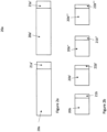
- a predictive algorithm is applied in this embodiment which calculates the delay in dependence upon the input file size of the electronic information as shown in Figure 2a and Figure 2b.
- Figure 2a shows how the delay 20a, 20a' is provided a first file size 21a, 21a' and Figure 2b shows how the delay 20b, 20b', 20b", 20b′′′ is provided for a second file size 21b, 21b', 21b", 21b"'.
- the delay algorithm is located at the input module 2 and is configured to calculate the state of the security module 4 based on the worst case scenarios of the behaviour of the wrapping algorithm located within the security module 4 and subsequent characteristics of the outbound path from the security module 4 towards the trusted network.
- the calculation allows the input module 2 to modulate the acceptance of data into the input module 2 from the lesser trusted network 7 and modulate the forwarding of data from the input module 2 to the security module 4 over the unidirectional pathway 5 to ensure that the security module 4 is able to accept the forwarded data.
- the modulation may take the form of inter-file delays or the form of inter-packet delays.
- the delay need not be constant between packets nor between files. Further, the delay may vary dependent upon measured network parameters.
- the delay algorithm at the input module 2 is implemented to calculate the state of the security module 4 dependent upon, from among others, the type of transformation applied e.g. wrapping algorithm used in the second electrical zone 4.
- the output module 3 transfers the file to the trusted network via tFTP or other method and can sort the locations of the files based upon their check state e.g. Good (unwrapped) or Bad (wrapped) or different file types may be forwarded to the same or different location in the trusted network. Accordingly, the wrapped file will always be transferred to the server for further analysis and/or for general reference.
- the electronic modules comprise processing means that are implemented as a "stripe" on a single PCB. From a manufacturing perspective, this ensures a physical separation between the processing means, such that if they are dedicated to one or more particular tasks, the layup or layout of components on a printed circuit board (PCB) or substrate can be easily managed, and from an assurance perspective, connections between each processing means can be physically verified. Connectivity between one or more stripes may be used to enforce a one-way data flow through the device 1.
- PCB printed circuit board
- At least one power supply unit 15 is provided to power the device which is in electrical communication with a switch 16 controllable on the trusted network 8. This permits the device to be self-contained, ensuring that from an assurance perspective there is no third-party tampering or additional features added when the data filter is powered.
- the modules are powered by the trusted network 8 from a power over Ethernet connection, for example through a RJ45 located within the device housing. The power is then forwarded to each of the three stripes that are connected to the respective modules. The power and data paths are separate and distinct. The three modules are therefore powered over the Ethernet, which is a convenient source for the user, not requiring external connections or power draw.
- This power over Ethernet (PoE) is sourced from a trusted network port so as to minimise the risk of side-channel communications. Therefore, each of the modules (or processors) take a common voltage feed, for example a 48V feed, however the set-up is configured to prevent unintended transmission of information between the most trusted network 8 and the lesser trusted network 7. For example, it is known to be able to monitor transformer characteristics as a way of determining information on the operation of a device e.g. by monitoring data transfer associated with the system to provide information on the actual data being transferred across the system. By ensuring that the power is supplied from the trusted Ethernet interface only then the ability of a third party accessing such information in this way is minimised.
- the module contains configuration code to load the field programmable gate arrays.
- a processor selection characteristic is implemented to ensure that the correct processor/module is linked with the correct FPGA, for example, a particular FPGA can only function with a predetermined processor which is identifiable by verifying the position of the processor/module. Therefore, the processor position is hard wired on the FPGA. This provides further certainty that there has not been any unintentional transfer of information between the most trusted interface with the lesser trusted interface.
- the separation of each of the processors (modules) is further assured by clearly identifying the individual circuitry on the board (e.g. by ensuring that the stripes are separate and distinct).
- This device 1 is implemented as an input device, therefore the power is supplied from the transmitting means 11 end. However, if this was to be used as an output device the power will still be supplied by the trusted end, but will be received by the receiver.
- the device comprises bitstream encryption (not shown).
- data for example configuration data, presented to or generated by the invention may not comprise more than a raw, unencoded bitstream, encrypting it adds a layer of commercial grade protection and assurance to hinder or prevent copying and/or reverse engineering of hardware designs, and/or to guard against malicious interception or disruption.
- SEU Single Event Upset
- mitigation which is deployed at the chip or system level to overwrite, rewrite or modify data to correct soft errors if, for example, it is wrong or has been corrupted, saving the user time in that they may avoid the need to perform a system reboot to correct such an error.
- the housing of the device (not shown) is clearly marked to indicate the direction of the unidirectional effect. This means that the direction of the flow of data/information through the transfer device 1 is clearly marked (not shown) on the external surface of the housing.
- the provision of only two connectors per data transfer device 1, one being the input and the other being the output also reduces the possibility of incorrectly installing the device 1.
- the mark may be, for example, a print of a circuit diagram of a diode.
- the mark may be formed in the outer surface of the housing during manufacture or applied subsequently to manufacture of the housing. The mark ensures that the receiver end of the filter and the transmitter end of the filter are clearly identifiable to the user.
- the desired direction of implementation is dependent on the intended use of the device i.e. as an import or export device.
- the form factor of the device 1 is designed to allow easy visual inspection that all the wires go to the correct ends of the device i.e. there is no overlap of the wires.
- the device 1 is configurable by a user, in that they may set the rules when decisions need to be made, or indeed determine which method steps are used, as well as determining other configurations such as determining destinations for the data when continuing, replication, backup regimes, etc.
- Increasing the external surface area of the housing of the device for example by providing fins or channelled side walls (not shown), maximises the cooling of the internal components, however further external cooling means known to the skilled reader may be provided to improve the cooling effect on this channelled side.
- the embodiment of the invention does not rely on the use of a software stack or CPU and as such there is no requirement for any patches to be implemented or further servicing to be provided.
- the verification and transformation capabilities of the device 1 make it suitable for use as a validator module for example in an Internet of Things (IoT) device, thereby providing a security offering in this field.
- the validator module 9 would be configured to sit in the data path and protect the device from malicious payloads (so making the attack surface much smaller).
- the Ethernet is inherently bidirectional and must remain so to operate as required. Therefore, the data transfer means located prior to the input module 2 and subsequent to the output module (in the first embodiment only) are also bi-directional.
- file transfer device 1 it is also possible to implement the file transfer device 1 using substantially equivalent hardware, such as Application Specific Integrated Circuit (ASIC), or a dedicated circuit as the user may require. Combinations of at least one or multiples of FPGAs, ASICs or integrated circuits may be applied. The provision of a validator ASIC for the Internet of Things application may be particularly beneficial.
- ASIC Application Specific Integrated Circuit
- the algorithms may be run using software on a general purpose Computer, but regular patches are likely to be required if this alternative is implemented and the attack surface would be substantially higher.
- receiving means should the user wish to receive data from more than one source
- transmitting means should the user wish to transmit data to more than one destination.
- the receiving means 10 and transmitting means 11 could comprise one unit.
- One or more data transfer devices 1 may be designed in to a PCB.
- the memory for the buffering need not be in the form of SDRAM, but may instead be equivalent memory types such as RAM, SRAM or static disc which could be used individually or collectively, for example the skilled person would be aware that the buffer limit can be overcome by subdividing the file to be ingested beforehand, such as tessellating a 2N x 2N bmp image into 4 NxN images.
- the file transfer device 1 can be used to export information from the trusted network 8 to the lesser trusted network 7 if desired. This is merely determined by the orientation of the device 1. To ensure the correct orientation of the device, the device is provided with a single input in the form of a first connector (for example a RJ45 connector), and a single output (for example a RJ45 connector). The data can only be transferred between the first connector and the second connector.
- the first connection means cooperates with one end of the first data transfer link, for example a cable such as a CAT 5 or 6 ethernet cable, and the other end of the data transfer link is connected to the first user interface.
- the second connection means cooperates with one end of the data transfer means for example a cable such as a CAT 5 or 6 ethernet cable, and the other end of the second data transfer means is connected to the second user interface. It is re-emphasised that this arrangement ensures there is no overlap between the first data transfer means and the second data transfer means which once again ensures the correct set up of the device and minimises the risk of permitting undesirable information transfer.
- this component need not be an amplifier, but may instead be an alternative unidirectional high speed serial communications component known to a person skilled in the art. Also, the SerDes pin may not be utilised.
- the device Whilst other candidates for text formats could be used e.g. JSON and XML, they may not be desirable due to, for example, their complexity or their lacking in richness to make the data self describing. Therefore, the device is more reliable when using a text format that can be validated in a simple state machine, whereby the text format is used as the predetermined file type. This beneficially minimises the attack surface of the validation engine, which is an important consideration in a security device.
- the device can be kept simple and reliable by using simpler file formats.
- An alternative way of running the algorithms is on a single board computer connected by a pair of one-way fibres.
- the data may be provided via serial cables and other non RJ45 connectors (e.g. fibre).
- it could be board mounted on a wider board and plumbed in using, for example a PCIe bus.
- the input file may declare it is of a size that is greater than the predetermined assured size limit an and the second module will trigger to wrap the file.
- the user has a set of preshared keys and places an index to reference a specific key that is used for encryption of the file.
- the key to be stored in the new header of the wrapped file may not be generated locally to the device, but may instead comprise a preshared key or an index to a list of preshared keys, for example a key dictionary.
- the device may permit transfer of the electronic data between the input module (i.e. first electrical zone) and the security module (i.e. second electrical zone) by means of a firewall.
- the unwrapped data can always be assured as being safe by the device. This is because if the file is lying about the file length being too long, or if it is telling the truth about the file length then in both circumstances the file will be automatically wrapped as it fails the file size check. In the case that the file asserts a short length on a long file could this be potentially problematic, however if the short file assertions are simply ignored this enables the device to revert back to the file size check.
- the delay of the file or the data packets may be provided by a hardware means (e.g. using a length of wire) rather than a software means.
- the time delay may depend on the bandwidth of the electrical connection between the lesser trusted network and the first electrical zone.
- the time delay may depend on the latency of an electrical connection located between the lesser trusted network and the first electrical zone.
- the time delay may depend on other properties of the electrical connection between the lesser trusted network and the first electrical zone. Such properties may comprise data loss, congestion and jitter.
- the security module 4 may be located with the output module 3 which is in communication with the trusted network 8 to form a combination second module (not shown).
- the combination second module (not shown) is therefore formed of a security electrical zone and an output electrical zone.
- the input module 2 can be considered an input zone.
- the input module 2 and combination second module (not shown) are connected via a unidirectional pathway 5.
- the electrical transfer between the circuitry of the security module 4 and the circuitry of the output module 3 is still provided by a unidirectional link.
- the electrical transfer between the circuitry of the security module 4 and the circuitry of the output module 3 is not provided by a unidirectional link, but by a conventional bi-directional cable or a line. In such an embodiment, the trust level of the verifier at the security zone is commensurate with that of the trusted network 8.
- a stream of data of indefinite duration (e.g. from a video feed) may be passed through the device 1. This is enabled due to a feature in the wrapping algorithm whereby the size of the file or data packet is not a parameter in the wrapping algorithm, which is important to allow the fast forwarding of non-compliant files.
Landscapes
- Engineering & Computer Science (AREA)
- Computer Security & Cryptography (AREA)
- General Engineering & Computer Science (AREA)
- Signal Processing (AREA)
- Computer Networks & Wireless Communication (AREA)
- Computing Systems (AREA)
- Computer Hardware Design (AREA)
- Theoretical Computer Science (AREA)
- Physics & Mathematics (AREA)
- Health & Medical Sciences (AREA)
- General Health & Medical Sciences (AREA)
- Virology (AREA)
- General Physics & Mathematics (AREA)
- Databases & Information Systems (AREA)
- Data Mining & Analysis (AREA)
- Human Computer Interaction (AREA)
- Storage Device Security (AREA)
- Data Exchanges In Wide-Area Networks (AREA)
- Computer And Data Communications (AREA)
Claims (14)
- Verfahren zum Übertragen von elektronischer Information zwischen einem minder vertrauenswürdigen Netzwerk (7) und einem vertrauenswürdigen Netzwerk (8) mit den Schritten:Empfangen von ursprünglicher elektronischer Information von einem minder vertrauenswürdigen Netzwerk (7) in einer ersten elektrischen Zone (4);Ermöglichen der Übertragung der ursprünglichen elektronischen Information zwischen der ersten elektrischen Zone (2) und einer zweiten elektrischen Zone (4) nur in einer Richtung;Verifizieren der ursprünglichen elektronischen Information in Bezug auf mindestens ein vorgegebenes Merkmal in der zweiten elektrischen Zone (4), um einen Verifiziererausgabestatus und verifizierte elektronische Information bereitzustellen;Weiterleiten der verifizierten elektronischen Information an eine dritte elektrische Zone (3), wobei die ursprüngliche elektronische Information aus der ersten elektrischen Zone (2) von der dritten elektrischen Zone (3) immer über die zweite elektrische Zone (4) als verifizierte elektronische Information in entweder einem transformierten Zustand oder einem nicht transformierten Zustand empfangen wird, wobei der transformierte Zustand oder der nicht transformierte Zustand in Abhängigkeit vom Verifiziererausgabestatus ausgewählt wird;Bereitstellen eines elektronischen Schlüssels; undim Gebrauch Erzeugen der verifizierten elektronischen Information im transformierten Zustand in Abhängigkeit von dem elektronischen Schlüssel;wobei das Verfahren dadurch gekennzeichnet ist,dass die verifizierte elektronische Information im transformierten Zustand die ursprüngliche elektronische Information in einer verpackten Form plus einen neuen Header umfasst, unddass der elektronische Schlüssel in dem neuen Header der verifizierten elektronischen Information im transformierten Zustand gespeichert wird, bevor die verifizierte elektronische Information im transformierten Zustand an die dritte elektrische Zone (3) weitergeleitet wird.
- Verfahren nach Anspruch 1, bei dem, wenn kein vorgegebenes Merkmal erfüllt ist, die ursprüngliche elektronische Information in die verifizierte elektronische Information in einem transformierten Zustand transformiert wird.
- Verfahren nach Anspruch 1 oder 2, bei dem die verifizierte elektronische Information in dem transformierten Zustand die ursprüngliche elektronische Information in einer verpackten Form umfasst, vorzugsweise unter Verwendung eines Verpackungsalgorithmus erstellt.
- Verfahren nach Anspruch 3, bei dem der elektronische Schlüssel lokal erzeugt wird, vorab geteilt wird oder einen Index zu einem Verzeichnis vorab geteilter elektronischer Schlüssel umfasst.
- Verfahren nach einem der vorhergehenden Ansprüche, bei dem der elektronische Schlüssel in Abhängigkeit vom Verifiziererausgabestatus bereitgestellt wird.
- Verfahren nach einem der vorhergehenden Ansprüche, bei dem die ursprüngliche elektronische Information eine Datei ist und bei dem die vorgegebene Eigenschaft den Dateityp umfasst.
- Verfahren nach einem der Ansprüche 1 bis 5, bei dem die ursprüngliche elektronische Information ein Datenstrom ist, der Datenpakete umfasst.
- Verfahren nach einem der vorhergehenden Ansprüche, bei dem das Verfahren, das die Übertragung der ursprünglichen elektronischen Information zwischen der ersten elektrischen Zone (2) und einer zweiten elektrischen Zone (4) nur in einer Richtung zulässt, die Verwendung eines unidirektionalen Pfads umfasst.
- Verfahren gemäß einem der vorhergehenden Ansprüche, bei dem die Übertragung der verifizierten elektronischen Information zwischen der zweiten elektrischen Zone (4) und der dritten elektrischen Zone (3) nur in einer Richtung zugelassen ist, vorzugsweise unter Verwendung eines unidirektionalen Pfads zwischen der zweiten elektrischen Zone (4) und der dritten elektrischen Zone (3).
- Vorrichtung zum Übertragen elektronischer Informationen von einem minder vertrauenswürdigen Netzwerk zu einem vertrauenswürdigen Netzwerk, mit:einer ersten elektrischen Zone (2) zum Empfangen von ursprünglicher elektronischer Information;einer zweiten elektrischen Zone (4), die einen Verifizierer (9) zum Verifizieren mindestens eines vorgegebenen Merkmals der ursprünglichen elektronischen Information umfasst, um einen Verifiziererausgabestatus und verifizierte elektronische Information bereitzustellen;mindestens einem Mittel zum Übertragen der ursprünglichen elektronischen Information zwischen der ersten elektrischen Zone (2) und der zweiten elektrischen Zone (4) nur in einer Richtung; undeiner dritten elektrischen Zone (3) zum Empfangen der verifizierten elektronischen Information von der zweiten elektrischen Zone (4);wobei die ursprüngliche elektronische Information aus der ersten elektrischen Zone (2) immer von der dritten elektrischen Zone (3) über die zweite elektrische Zone (4) als verifizierte elektronische Information in entweder einem transformierten Zustand oder einem nicht transformierten Zustand empfangen wird, wobei ferner der transformierte Zustand oder der nicht transformierte Zustand in Abhängigkeit von dem Verifiziererausgabestatus ausgewählt wird;wobei die zweite elektrische Zone (4) ein Mittel zum Bereitstellen eines elektronischen Schlüssels umfasst;wobei die zweite elektrische Zone ein Mittel (14) zum Umwandeln der ursprünglichen elektronischen Information in verifizierte elektronische Information im transformierten Zustand in Abhängigkeit von dem elektronischen Schlüssel umfasst,wobei die Vorrichtung dadurch gekennzeichnet ist, dassdie verifizierte elektronische Information im transformierten Zustand die ursprüngliche elektronische Information in einer verpackten Form plus einen neuen Header umfasst, undder elektronische Schlüssel im Header der verifizierten elektronischen Information bereitgestellt wird.
- Vorrichtung nach Anspruch 10, bei der die ursprüngliche elektronische Information eine Datei umfasst und bei der die verifizierte elektronische Information in einem transformierten Zustand eine verpackte Datei mit einer Dateigröße umfasst, die der Größe der Datei plus der Größe eines neuen Headers entspricht.
- Vorrichtung nach Anspruch 10 oder 11, die ferner einen Verzögerungsgenerator zum Verzögern der Eingabe der ursprünglichen elektronischen Information in die erste elektrische Zone (2) umfasst.
- Vorrichtung nach einem der Ansprüche 10 bis 12, bei der die erste elektrische Zone (2) von der zweiten elektrischen Zone (4) und der dritten elektrischen Zone (3) getrennt und verschieden ist und das mindestens eine Mittel (5) zum Übertragen der ursprünglichen elektronischen Information zwischen der ersten elektrischen Zone (2) und der zweiten elektrischen Zone (4) in nur einer Richtung einen unidirektionalen Pfad umfasst, der sich zwischen der ersten elektrischen Zone (2) und der zweiten elektrischen Zone (4) befindet.
- Vorrichtung nach Anspruch 13, bei der der mindestens eine unidirektionale Pfad mindestens eine Hardwarekomponente umfasst, vorzugsweise mindestens einen SerDes-Pin und/oder einen unidirektionalen Verstärker.
Applications Claiming Priority (2)
| Application Number | Priority Date | Filing Date | Title |
|---|---|---|---|
| GBGB1815120.9A GB201815120D0 (en) | 2018-09-17 | 2018-09-17 | A method and device for transferring electronic information |
| PCT/GB2019/000131 WO2020058658A1 (en) | 2018-09-17 | 2019-09-14 | A method and device for transferring electronic information |
Publications (2)
| Publication Number | Publication Date |
|---|---|
| EP3854054A1 EP3854054A1 (de) | 2021-07-28 |
| EP3854054B1 true EP3854054B1 (de) | 2024-11-06 |
Family
ID=64013195
Family Applications (2)
| Application Number | Title | Priority Date | Filing Date |
|---|---|---|---|
| EP19770144.4A Active EP3854054B1 (de) | 2018-09-17 | 2019-09-14 | Übertragung elektronischer daten zwischen netzwerken von verschiedenem vertrauensniveau |
| EP19770145.1A Active EP3854055B1 (de) | 2018-09-17 | 2019-09-14 | Übertragen von elektronischen informationen mit einem zeitlichen verzug |
Family Applications After (1)
| Application Number | Title | Priority Date | Filing Date |
|---|---|---|---|
| EP19770145.1A Active EP3854055B1 (de) | 2018-09-17 | 2019-09-14 | Übertragen von elektronischen informationen mit einem zeitlichen verzug |
Country Status (8)
| Country | Link |
|---|---|
| US (2) | US12542759B2 (de) |
| EP (2) | EP3854054B1 (de) |
| AU (2) | AU2019342301B2 (de) |
| CA (2) | CA3112894A1 (de) |
| DK (2) | DK3854055T3 (de) |
| ES (2) | ES3000467T3 (de) |
| GB (3) | GB201815120D0 (de) |
| WO (2) | WO2020058659A1 (de) |
Family Cites Families (13)
| Publication number | Priority date | Publication date | Assignee | Title |
|---|---|---|---|---|
| US9015467B2 (en) * | 2002-12-05 | 2015-04-21 | Broadcom Corporation | Tagging mechanism for data path security processing |
| US7406101B1 (en) * | 2004-12-10 | 2008-07-29 | National Semiconductor Corporation | System and method for providing on-chip delay measurements in serializer / deserializer systems |
| DE102007043892A1 (de) * | 2007-09-14 | 2009-03-19 | Eads Deutschland Gmbh | Verfahren zur Übermittlung einer elektronischen Nachricht in einem Transportnetzwerk |
| WO2011135452A2 (en) * | 2010-04-30 | 2011-11-03 | Ad Group | An ip-closed circuit system and method |
| US8842675B2 (en) * | 2012-08-23 | 2014-09-23 | L-3 Communications Corporation | Systems and methods for multicore processing of data with in-sequence delivery |
| JP5958975B2 (ja) * | 2014-03-10 | 2016-08-02 | トヨタ自動車株式会社 | 通信装置、通信方法及び通信システム |
| DE102015205833A1 (de) * | 2015-03-31 | 2016-10-06 | Siemens Aktiengesellschaft | Einweg-Koppelvorrichtung, Anfrageeinrichtung und Verfahren zum rückwirkungsfreien Übertragen von Daten |
| US10713587B2 (en) * | 2015-11-09 | 2020-07-14 | Xerox Corporation | Method and system using machine learning techniques for checking data integrity in a data warehouse feed |
| US9967234B1 (en) * | 2016-04-27 | 2018-05-08 | The United States Of America, As Represented By The Secretary Of The Navy | Miniaturized real time pseudo-cross domain data communication system with air gapped full motion video device and method |
| EP3278513B1 (de) * | 2016-04-29 | 2020-03-18 | Hewlett-Packard Enterprise Development LP | Umwandlung eines dienstpakets von einer ersten domäne in eine zweite domäne |
| US10270745B2 (en) * | 2016-10-24 | 2019-04-23 | Fisher-Rosemount Systems, Inc. | Securely transporting data across a data diode for secured process control communications |
| GB2556636A (en) * | 2016-11-21 | 2018-06-06 | The Sec Dep For Foreign And Commonwealth Affairs | Method and device for filtering packets |
| FR3061389B1 (fr) * | 2016-12-22 | 2019-05-31 | Airbus Defence And Space Sas | Systeme et procede de communication unidirectionnel |
-
2018
- 2018-09-17 GB GBGB1815120.9A patent/GB201815120D0/en not_active Ceased
-
2019
- 2019-09-14 EP EP19770144.4A patent/EP3854054B1/de active Active
- 2019-09-14 ES ES19770144T patent/ES3000467T3/es active Active
- 2019-09-14 AU AU2019342301A patent/AU2019342301B2/en active Active
- 2019-09-14 US US17/276,135 patent/US12542759B2/en active Active
- 2019-09-14 US US17/276,137 patent/US11916871B2/en active Active
- 2019-09-14 WO PCT/GB2019/000132 patent/WO2020058659A1/en not_active Ceased
- 2019-09-14 DK DK19770145.1T patent/DK3854055T3/da active
- 2019-09-14 GB GB2104734.5A patent/GB2591936B/en active Active
- 2019-09-14 WO PCT/GB2019/000131 patent/WO2020058658A1/en not_active Ceased
- 2019-09-14 ES ES19770145T patent/ES3008939T3/es active Active
- 2019-09-14 CA CA3112894A patent/CA3112894A1/en active Pending
- 2019-09-14 GB GB2104732.9A patent/GB2591934B/en active Active
- 2019-09-14 DK DK19770144.4T patent/DK3854054T3/da active
- 2019-09-14 EP EP19770145.1A patent/EP3854055B1/de active Active
- 2019-09-14 CA CA3112881A patent/CA3112881A1/en active Pending
- 2019-09-14 AU AU2019343504A patent/AU2019343504B2/en active Active
Also Published As
| Publication number | Publication date |
|---|---|
| WO2020058659A1 (en) | 2020-03-26 |
| WO2020058658A1 (en) | 2020-03-26 |
| NZ774019A (en) | 2025-05-02 |
| GB2591934A (en) | 2021-08-11 |
| GB202104732D0 (en) | 2021-05-19 |
| US12542759B2 (en) | 2026-02-03 |
| GB2591934B (en) | 2023-04-26 |
| EP3854054A1 (de) | 2021-07-28 |
| US20220052982A1 (en) | 2022-02-17 |
| US11916871B2 (en) | 2024-02-27 |
| GB202104734D0 (en) | 2021-05-19 |
| EP3854055A1 (de) | 2021-07-28 |
| AU2019343504A1 (en) | 2021-04-15 |
| AU2019342301B2 (en) | 2025-04-03 |
| DK3854055T3 (da) | 2025-01-20 |
| DK3854054T3 (da) | 2025-01-20 |
| ES3000467T3 (en) | 2025-02-28 |
| CA3112881A1 (en) | 2020-03-26 |
| ES3008939T3 (en) | 2025-03-25 |
| EP3854055B1 (de) | 2024-11-13 |
| GB201815120D0 (en) | 2018-10-31 |
| NZ774022A (en) | 2025-07-25 |
| GB2591936B (en) | 2022-11-16 |
| US20220052983A1 (en) | 2022-02-17 |
| CA3112894A1 (en) | 2020-03-26 |
| AU2019342301A1 (en) | 2021-04-15 |
| AU2019343504B2 (en) | 2025-04-10 |
| GB2591936A (en) | 2021-08-11 |
Similar Documents
| Publication | Publication Date | Title |
|---|---|---|
| US8732453B2 (en) | Secure acknowledgment device for one-way data transfer system | |
| KR102195788B1 (ko) | 호스트 컴퓨팅 디바이스와 주변기기의 데이터의 보안을 강화하기 위한 장치 및 방법 | |
| EP1631914B1 (de) | Verfahren und system zur bereitstellung eines sicheren einseitigen transfers von daten | |
| US8646094B2 (en) | Method and apparatus for preventing unauthorized access to information stored in a non-volatile memory | |
| US6865672B1 (en) | System and method for securing a computer communication network | |
| US10303881B2 (en) | Soft-wired radio (SWR) web machine | |
| CN120513608A (zh) | 数据传输方法、系统、第一端、中间网络设备及控制设备 | |
| CN112653664A (zh) | 一种网络之间高安全可靠的数据交换系统及方法 | |
| US8285984B2 (en) | Secure network extension device and method | |
| EP3854054B1 (de) | Übertragung elektronischer daten zwischen netzwerken von verschiedenem vertrauensniveau | |
| Goh et al. | Experimenting with an intrusion detection system for encrypted networks | |
| US11093616B2 (en) | Soft-wired radio (SWR) web machine | |
| US12169589B1 (en) | Apparatus and methods relying on non-flashable circuitry for improving security for a system connected to a public or private network | |
| US20150319188A1 (en) | Canonical Network Isolator Component | |
| Bartzoudis et al. | Reconfigurable Computing and Active Networks. | |
| TW202527513A (zh) | 數據傳輸控制方法、系統、控制設備及可讀存儲介質 | |
| Blomquist et al. | Secure Continuous Deployment of Military Software | |
| An et al. | DESIGN OF UNIDIRECTIONAL SECURITY GATEWAY DEVICE FOR SECURE DATA TRANSFER |
Legal Events
| Date | Code | Title | Description |
|---|---|---|---|
| STAA | Information on the status of an ep patent application or granted ep patent |
Free format text: STATUS: UNKNOWN |
|
| STAA | Information on the status of an ep patent application or granted ep patent |
Free format text: STATUS: THE INTERNATIONAL PUBLICATION HAS BEEN MADE |
|
| PUAI | Public reference made under article 153(3) epc to a published international application that has entered the european phase |
Free format text: ORIGINAL CODE: 0009012 |
|
| STAA | Information on the status of an ep patent application or granted ep patent |
Free format text: STATUS: REQUEST FOR EXAMINATION WAS MADE |
|
| 17P | Request for examination filed |
Effective date: 20210408 |
|
| AK | Designated contracting states |
Kind code of ref document: A1 Designated state(s): AL AT BE BG CH CY CZ DE DK EE ES FI FR GB GR HR HU IE IS IT LI LT LU LV MC MK MT NL NO PL PT RO RS SE SI SK SM TR |
|
| DAV | Request for validation of the european patent (deleted) | ||
| DAX | Request for extension of the european patent (deleted) | ||
| STAA | Information on the status of an ep patent application or granted ep patent |
Free format text: STATUS: EXAMINATION IS IN PROGRESS |
|
| 17Q | First examination report despatched |
Effective date: 20220905 |
|
| RBV | Designated contracting states (corrected) |
Designated state(s): AL AT BE BG CH CY CZ DE DK EE ES FI FR GR HR HU IE IS IT LI LT LU LV MC MK MT NL NO PL PT RO RS SE SI SK SM TR |
|
| P01 | Opt-out of the competence of the unified patent court (upc) registered |
Effective date: 20230511 |
|
| REG | Reference to a national code |
Ref country code: DE Ref legal event code: R079 Free format text: PREVIOUS MAIN CLASS: H04L0029060000 Ipc: H04L0009400000 Ref country code: DE Ref legal event code: R079 Ref document number: 602019061539 Country of ref document: DE Free format text: PREVIOUS MAIN CLASS: H04L0029060000 Ipc: H04L0009400000 |
|
| GRAP | Despatch of communication of intention to grant a patent |
Free format text: ORIGINAL CODE: EPIDOSNIGR1 |
|
| STAA | Information on the status of an ep patent application or granted ep patent |
Free format text: STATUS: GRANT OF PATENT IS INTENDED |
|
| RIC1 | Information provided on ipc code assigned before grant |
Ipc: G06F 16/16 20190101ALI20240430BHEP Ipc: H04L 9/40 20220101AFI20240430BHEP |
|
| INTG | Intention to grant announced |
Effective date: 20240604 |
|
| GRAS | Grant fee paid |
Free format text: ORIGINAL CODE: EPIDOSNIGR3 |
|
| GRAA | (expected) grant |
Free format text: ORIGINAL CODE: 0009210 |
|
| STAA | Information on the status of an ep patent application or granted ep patent |
Free format text: STATUS: THE PATENT HAS BEEN GRANTED |
|
| AK | Designated contracting states |
Kind code of ref document: B1 Designated state(s): AL AT BE BG CH CY CZ DE DK EE ES FI FR GR HR HU IE IS IT LI LT LU LV MC MK MT NL NO PL PT RO RS SE SI SK SM TR |
|
| REG | Reference to a national code |
Ref country code: CH Ref legal event code: EP |
|
| REG | Reference to a national code |
Ref country code: DE Ref legal event code: R096 Ref document number: 602019061539 Country of ref document: DE |
|
| REG | Reference to a national code |
Ref country code: IE Ref legal event code: FG4D |
|
| REG | Reference to a national code |
Ref country code: NL Ref legal event code: FP |
|
| REG | Reference to a national code |
Ref country code: DK Ref legal event code: T3 Effective date: 20250114 |
|
| REG | Reference to a national code |
Ref country code: SE Ref legal event code: TRGR |
|
| REG | Reference to a national code |
Ref country code: ES Ref legal event code: FG2A Ref document number: 3000467 Country of ref document: ES Kind code of ref document: T3 Effective date: 20250228 |
|
| REG | Reference to a national code |
Ref country code: LT Ref legal event code: MG9D |
|
| PG25 | Lapsed in a contracting state [announced via postgrant information from national office to epo] |
Ref country code: HR Free format text: LAPSE BECAUSE OF FAILURE TO SUBMIT A TRANSLATION OF THE DESCRIPTION OR TO PAY THE FEE WITHIN THE PRESCRIBED TIME-LIMIT Effective date: 20241106 Ref country code: IS Free format text: LAPSE BECAUSE OF FAILURE TO SUBMIT A TRANSLATION OF THE DESCRIPTION OR TO PAY THE FEE WITHIN THE PRESCRIBED TIME-LIMIT Effective date: 20250306 Ref country code: PT Free format text: LAPSE BECAUSE OF FAILURE TO SUBMIT A TRANSLATION OF THE DESCRIPTION OR TO PAY THE FEE WITHIN THE PRESCRIBED TIME-LIMIT Effective date: 20250306 |
|
| PG25 | Lapsed in a contracting state [announced via postgrant information from national office to epo] |
Ref country code: FI Free format text: LAPSE BECAUSE OF FAILURE TO SUBMIT A TRANSLATION OF THE DESCRIPTION OR TO PAY THE FEE WITHIN THE PRESCRIBED TIME-LIMIT Effective date: 20241106 |
|
| REG | Reference to a national code |
Ref country code: AT Ref legal event code: MK05 Ref document number: 1740587 Country of ref document: AT Kind code of ref document: T Effective date: 20241106 |
|
| PG25 | Lapsed in a contracting state [announced via postgrant information from national office to epo] |
Ref country code: BG Free format text: LAPSE BECAUSE OF FAILURE TO SUBMIT A TRANSLATION OF THE DESCRIPTION OR TO PAY THE FEE WITHIN THE PRESCRIBED TIME-LIMIT Effective date: 20241106 |
|
| PG25 | Lapsed in a contracting state [announced via postgrant information from national office to epo] |
Ref country code: LV Free format text: LAPSE BECAUSE OF FAILURE TO SUBMIT A TRANSLATION OF THE DESCRIPTION OR TO PAY THE FEE WITHIN THE PRESCRIBED TIME-LIMIT Effective date: 20241106 Ref country code: AT Free format text: LAPSE BECAUSE OF FAILURE TO SUBMIT A TRANSLATION OF THE DESCRIPTION OR TO PAY THE FEE WITHIN THE PRESCRIBED TIME-LIMIT Effective date: 20241106 Ref country code: GR Free format text: LAPSE BECAUSE OF FAILURE TO SUBMIT A TRANSLATION OF THE DESCRIPTION OR TO PAY THE FEE WITHIN THE PRESCRIBED TIME-LIMIT Effective date: 20250207 |
|
| PG25 | Lapsed in a contracting state [announced via postgrant information from national office to epo] |
Ref country code: PL Free format text: LAPSE BECAUSE OF FAILURE TO SUBMIT A TRANSLATION OF THE DESCRIPTION OR TO PAY THE FEE WITHIN THE PRESCRIBED TIME-LIMIT Effective date: 20241106 |
|
| PG25 | Lapsed in a contracting state [announced via postgrant information from national office to epo] |
Ref country code: RS Free format text: LAPSE BECAUSE OF FAILURE TO SUBMIT A TRANSLATION OF THE DESCRIPTION OR TO PAY THE FEE WITHIN THE PRESCRIBED TIME-LIMIT Effective date: 20250206 |
|
| PG25 | Lapsed in a contracting state [announced via postgrant information from national office to epo] |
Ref country code: SM Free format text: LAPSE BECAUSE OF FAILURE TO SUBMIT A TRANSLATION OF THE DESCRIPTION OR TO PAY THE FEE WITHIN THE PRESCRIBED TIME-LIMIT Effective date: 20241106 |
|
| PG25 | Lapsed in a contracting state [announced via postgrant information from national office to epo] |
Ref country code: EE Free format text: LAPSE BECAUSE OF FAILURE TO SUBMIT A TRANSLATION OF THE DESCRIPTION OR TO PAY THE FEE WITHIN THE PRESCRIBED TIME-LIMIT Effective date: 20241106 |
|
| PG25 | Lapsed in a contracting state [announced via postgrant information from national office to epo] |
Ref country code: RO Free format text: LAPSE BECAUSE OF FAILURE TO SUBMIT A TRANSLATION OF THE DESCRIPTION OR TO PAY THE FEE WITHIN THE PRESCRIBED TIME-LIMIT Effective date: 20241106 |
|
| PG25 | Lapsed in a contracting state [announced via postgrant information from national office to epo] |
Ref country code: SK Free format text: LAPSE BECAUSE OF FAILURE TO SUBMIT A TRANSLATION OF THE DESCRIPTION OR TO PAY THE FEE WITHIN THE PRESCRIBED TIME-LIMIT Effective date: 20241106 |
|
| PG25 | Lapsed in a contracting state [announced via postgrant information from national office to epo] |
Ref country code: CZ Free format text: LAPSE BECAUSE OF FAILURE TO SUBMIT A TRANSLATION OF THE DESCRIPTION OR TO PAY THE FEE WITHIN THE PRESCRIBED TIME-LIMIT Effective date: 20241106 |
|
| PG25 | Lapsed in a contracting state [announced via postgrant information from national office to epo] |
Ref country code: IT Free format text: LAPSE BECAUSE OF FAILURE TO SUBMIT A TRANSLATION OF THE DESCRIPTION OR TO PAY THE FEE WITHIN THE PRESCRIBED TIME-LIMIT Effective date: 20241106 |
|
| REG | Reference to a national code |
Ref country code: DE Ref legal event code: R097 Ref document number: 602019061539 Country of ref document: DE |
|
| PLBE | No opposition filed within time limit |
Free format text: ORIGINAL CODE: 0009261 |
|
| STAA | Information on the status of an ep patent application or granted ep patent |
Free format text: STATUS: NO OPPOSITION FILED WITHIN TIME LIMIT |
|
| PGFP | Annual fee paid to national office [announced via postgrant information from national office to epo] |
Ref country code: DK Payment date: 20250915 Year of fee payment: 7 |
|
| PGFP | Annual fee paid to national office [announced via postgrant information from national office to epo] |
Ref country code: NO Payment date: 20250731 Year of fee payment: 7 |
|
| 26N | No opposition filed |
Effective date: 20250807 |
|
| PGFP | Annual fee paid to national office [announced via postgrant information from national office to epo] |
Ref country code: BE Payment date: 20250925 Year of fee payment: 7 |
|
| PGFP | Annual fee paid to national office [announced via postgrant information from national office to epo] |
Ref country code: FR Payment date: 20250728 Year of fee payment: 7 |
|
| PGFP | Annual fee paid to national office [announced via postgrant information from national office to epo] |
Ref country code: SE Payment date: 20250801 Year of fee payment: 7 |
|
| PGFP | Annual fee paid to national office [announced via postgrant information from national office to epo] |
Ref country code: ES Payment date: 20251002 Year of fee payment: 7 |