EP3853981B1 - Motor vehicle auxiliary unit - Google Patents
Motor vehicle auxiliary unit Download PDFInfo
- Publication number
- EP3853981B1 EP3853981B1 EP18772788.8A EP18772788A EP3853981B1 EP 3853981 B1 EP3853981 B1 EP 3853981B1 EP 18772788 A EP18772788 A EP 18772788A EP 3853981 B1 EP3853981 B1 EP 3853981B1
- Authority
- EP
- European Patent Office
- Prior art keywords
- stator body
- contact
- motor
- motor vehicle
- auxiliary unit
- Prior art date
- Legal status (The legal status is an assumption and is not a legal conclusion. Google has not performed a legal analysis and makes no representation as to the accuracy of the status listed.)
- Active
Links
- 239000011248 coating agent Substances 0.000 claims description 10
- 238000000576 coating method Methods 0.000 claims description 10
- 230000005294 ferromagnetic effect Effects 0.000 claims description 5
- 230000005291 magnetic effect Effects 0.000 claims description 4
- 230000000149 penetrating effect Effects 0.000 claims description 3
- 238000000034 method Methods 0.000 description 5
- 238000002955 isolation Methods 0.000 description 4
- 239000002184 metal Substances 0.000 description 3
- 230000005855 radiation Effects 0.000 description 3
- 239000000446 fuel Substances 0.000 description 2
- 239000002828 fuel tank Substances 0.000 description 2
- 238000005086 pumping Methods 0.000 description 2
- 238000010438 heat treatment Methods 0.000 description 1
- 230000007257 malfunction Effects 0.000 description 1
- 239000004065 semiconductor Substances 0.000 description 1
- 230000003068 static effect Effects 0.000 description 1
Images


Classifications
-
- H—ELECTRICITY
- H02—GENERATION; CONVERSION OR DISTRIBUTION OF ELECTRIC POWER
- H02K—DYNAMO-ELECTRIC MACHINES
- H02K11/00—Structural association of dynamo-electric machines with electric components or with devices for shielding, monitoring or protection
- H02K11/40—Structural association with grounding devices
-
- H—ELECTRICITY
- H02—GENERATION; CONVERSION OR DISTRIBUTION OF ELECTRIC POWER
- H02K—DYNAMO-ELECTRIC MACHINES
- H02K5/00—Casings; Enclosures; Supports
- H02K5/04—Casings or enclosures characterised by the shape, form or construction thereof
- H02K5/22—Auxiliary parts of casings not covered by groups H02K5/06-H02K5/20, e.g. shaped to form connection boxes or terminal boxes
- H02K5/225—Terminal boxes or connection arrangements
-
- H—ELECTRICITY
- H02—GENERATION; CONVERSION OR DISTRIBUTION OF ELECTRIC POWER
- H02K—DYNAMO-ELECTRIC MACHINES
- H02K1/00—Details of the magnetic circuit
- H02K1/06—Details of the magnetic circuit characterised by the shape, form or construction
- H02K1/12—Stationary parts of the magnetic circuit
- H02K1/14—Stator cores with salient poles
- H02K1/141—Stator cores with salient poles consisting of C-shaped cores
- H02K1/143—Stator cores with salient poles consisting of C-shaped cores of the horse-shoe type
-
- H—ELECTRICITY
- H02—GENERATION; CONVERSION OR DISTRIBUTION OF ELECTRIC POWER
- H02K—DYNAMO-ELECTRIC MACHINES
- H02K11/00—Structural association of dynamo-electric machines with electric components or with devices for shielding, monitoring or protection
- H02K11/30—Structural association with control circuits or drive circuits
- H02K11/33—Drive circuits, e.g. power electronics
Definitions
- the invention is directed to a motor vehicle auxiliary unit, for example to an electric gas pump for pumping fuel vapor out of a motor vehicle fuel tank.
- Such a motor vehicle auxiliary unit comprises an electronically commutated electric motor with a permanent magnetic motor rotor, with a motor stator with a ferromagnetic stator body and at least one stator coil, as well as with a motor electronics with a ground terminal for electrically connecting the motor electronics with an external vehicle ground potential.
- the motor vehicle auxiliary unit also comprises a unit connector plug for externally energizing and, optionally, for controlling the motor vehicle auxiliary unit.
- the unit connector plug comprises at least an external-ground connector lug for electrically connecting the motor vehicle auxiliary unit with an external vehicle ground potential.
- the external-ground connector lug is internally directly connected with the motor electronics ground terminal for electrically connecting the motor electronics ground terminal with the external vehicle ground potential.
- the electronically commutated electric motor of the motor vehicle auxiliary unit generates electromagnetic interference radiation, which can cause malfunctions or even failure of other electronic devices in the vicinity of the electric motor.
- the interference radiation can, for example, interfere with the motor electronics of the electric motor.
- electronic devices have to fulfill application-specific electromagnetic compatibility (EMC) directives.
- EMC electromagnetic compatibility
- the electric motor is provided with a stator body contact element providing a direct electric connection between the motor electronics ground terminal and the stator body to minimize the electromagnetic interference radiation being generated by the electric motor.
- An electric motor with a stator body contact element electrically connecting the stator body with the motor electronics is, for example, disclosed in EP 3 007 330 B1 .
- the stator body contact element is fixed to the stator body with one axial end and is plugged into a motor electronics ground terminal with the opposite axial end.
- the stator body contact element has to be exactly positioned and aligned during the assembling process to fit into the corresponding motor electronics terminal.
- EP 3 340 444 A2 discloses a radiator fan module with an electric motor and with a connector cable.
- the radiator fan module comprises a punched-grid connection element for connecting wires of the connector cable with a printed circuit board.
- the punched-grid connection element comprises a stator body contact element which provides an electric connection between an external-ground wire of the connector cable and a stator body of the electric motor.
- EP 2 500 576 A1 discloses a heating system circulator pump with an electric motor and with a connector plug.
- the connector plug comprises an external-ground connector lug which is directly electrically connected with a ground terminal of a circuit board.
- the external-ground connector lug comprises a housing contact element which provides a direct electric connection with a housing of the electric motor.
- the electric motor of the motor vehicle auxiliary unit is also provided with a motor electronics being electrically connected with the stator coil for energizing the stator coil and thereby driving the motor rotor.
- the motor electronics comprises several power semiconductors for commutating the electric drive energy being provided to the stator coil.
- the motor electronics also comprises a ground terminal for electrically connecting the motor electronics with an external vehicle ground potential to provide the motor electronics with electric energy.
- the motor vehicle auxiliary unit is also provided with a unit connector plug for externally energizing and controlling the motor vehicle auxiliary unit.
- the unit connector plug comprises at least an external-ground connector lug for electrically connecting the motor vehicle auxiliary unit with an external vehicle ground potential.
- the external-ground connector lug is made of a metal and provides a direct low-resistive electric connection with the motor electronics ground terminal. All connector lugs of the unit connector plug are typically simultaneously stamped out of a metal sheet and are post-processed by a mechanical deformation process.
- the external-ground connector lug is provided with an integral stator body contact element providing a direct electric connection with the stator body.
- the external-ground connector lug is provided as a single-piece three-way electric connector providing a direct electric interconnection between an external contact pin being electrically connectable with the vehicle ground potential, the motor electronics and the stator body.
- the stator body contact element extends from the external contact pin to the stator body and is reliably fixed to the stator body, for example by overmolding.
- the electric connection with the motor electronics is provided by an integral motor electronics contact element which extends from the external contact pin to the motor electronics and typically is plugged into a correspondingly shaped ground terminal of the motor electronics.
- stator body contact element is integrated into the unit connector plug, no additional contact element is required, which has to be separately mounted and aligned.
- the motor vehicle auxiliary unit according to the invention can be assembled in a simple way.
- the integral contact element also reduces the number of junctions in the electric connection between the stator body and the vehicle ground potential and, as a result, reduces the total electric resistance of this electric connection.
- the direct electric connection between the stator body, the motor electronics ground terminal and the external-ground potential ensures good EMC characteristics of the motor vehicle auxiliary unit according to the invention.
- a transversal stator body top side is provided with an axial contact opening, wherein the stator body contact element is plugged into the contact opening.
- the stator body is provided with an electrically isolating protection coating.
- the stator body contact element is preferably provided with at least one cutting element penetrating the isolating stator body coating to provide an electric contact with the stator body.
- the cutting element also fixes the external-ground connector lug to the stator body.
- the contact ring is provided with an axially extending plug cylinder and with a support flange laterally projecting from the plug cylinder.
- the plug cylinder is plugged into the contact opening and radially contacts the inside surface of the contact opening.
- the support flange is in axial contact with the stator body top side to define the intrusion depth of the plug cylinder into the contact opening. This provides a simple and reliable positioning of the external-ground connector lug with respect to the stator body.
- the outside diameter of the plug cylinder is slightly larger than the opening diameter of the contact opening.
- the term "opening diameter” always means the diameter of the unstressed contact opening, i.e. the diameter of the contact opening before the stator body contact element is plugged into the contact opening. Since the plug cylinder outside diameter is slightly larger than the opening diameter of the contact opening, the plug cylinder abrades the isolation from the inside surface of the contact opening when being pressed into the contact opening. As a result, the plug cylinder provides a reliable electric contact with the stator body as well as a robust fixation of the external-ground connector lug to the stator body.
- the contact ring is provided with several cutting elements which are distributed along the outside circumference of the contact ring and which axially protrude over the contact ring bottom side.
- the cutting elements penetrate the stator body isolation coating if the contact ring is pressed against the stator body top side.
- the penetrating cutting elements provide a reliable electric connection and avoid a lateral shifting of the stator body contact element with respect to the stator body.
- a separate fastening means is provided which extends through the contact ring into the contact opening and axially presses the contact ring against the stator body top side.
- the fastening means is provided with an axially extending pin and a laterally extending head.
- the pin axially extends through the contact ring into the contact opening to fix the fastening means within or at the stator body in that way that the head axially presses the contact ring against the stator body.
- the fastening means can, for example, be a rivet or a screw.
- the fastening means provides a robust fixation of the external-ground connector lug.
- the axial pressure generated by the fastening means also provides a reliable electric contact with the stator body, in particular if the stator body contact element is provided with cutting elements.
- the unit connector plug also comprises a power connector lug being electrically connected with the motor electronics for energizing the motor electronics so that no additional connector plug is required for energizing the motor electronics.
- the motor vehicle auxiliary unit is provided with a sensor element and the unit connector plug comprises at least one sensor connector lug being electrically connected with the sensor element.
- the sensor element can, for example, be a pressure sensor or a speed sensor being externally readable/programmable via the sensor connector lug of the unit connector plug. As a result, no additional sensor connector plug is required.
- the electric motor 12 comprises a rotatable permanent magnetic motor rotor 20 and a static motor stator 22 with a ferromagnetic stator body 24 and a single stator coil 26.
- the motor rotor 20 is co-rotatably connected with the pump wheel 14.
- the stator body 24 is a laminated stator body which is coated with an electrically isolating protection coating 27.
- the stator body 24 is provided with an axial contact opening 46 which in the present embodiment of the invention is provided with a circular cross section and which extends from a stator body top side 48 along the entire axial height of the stator body 24 to a stator body bottom side 50.
- the electric motor 12 also comprises a motor electronics 28 being electrically connected to the stator coil 26 for energizing the stator coil 26 for driving the motor rotor 20 and, as a result, for driving the pump wheel 14.
- the unit connector plug 18 comprises a plug housing 30 and is provided with three sensor connector lugs 32, a power connector lug 34 and an external-ground connector lug 36, which are externally electrically contactable. All connector lugs 32,34,36 are stamped out of a single metal sheet and post-processed by a mechanical deformation process.
- the sensor connector lugs 32 are internally electrically connected with the sensor element 16 for energizing the sensor element 16 and/or for providing a data interface for reading/writing data from/to the sensor element 16.
- the power connector lug 34 is internally electrically connected with the motor electronics 28 and externally connectable to an external energy source, for example to a motor vehicle battery, for providing the motor electronics 28 with electric energy.
- the external-ground connector lug 36 is provided as a single-piece three-way electric connector comprising an external-ground pin 38, a motor electronics contact element 40 and a stator body contact element 42.
- the external-ground pin 38 is externally connectable to an external motor vehicle ground potential.
- the motor electronics contact element 40 provides a direct electric connection with the motor electronics 28, in particular with a ground terminal 44 of the motor electronics 28.
- the stator body contact element 42 provides a direct electric contact with the stator body 24.
- the stator body contact element 42 is provided with a substantially laterally extending support bar 52 and with an arrowhead-shaped cutting element 54.
- the stator body contact element 42 is plugged into the contact opening 46 in that way that the support bar 52 is in axial contact with the stator body top side 48 and that the cutting element 54 intrudes into the contact opening 46.
- the lateral width of the cutting element 54 is slightly larger than the opening diameter of the contact opening 46 so that the cutting element 54 cuts into the sidewalls of the contact opening 46.
- the cutting element 54 cuts through the isolation coating 27 of the stator body 24 so that the cutting element 54 provides a reliable electric contact with the stator body 24.
- the cutting element 54 also reliably positions the stator body contact element 42 with respect to the stator body 24 during the assembling process.
- the stator body contact element 42" is fastened to the stator body 24 by a separate fastening means 62 which in the present embodiment of the invention is a screw with a transversal screw head 64 and an axially extending screw pin 66.
- the screw head 64 is in axial contact with the top side of the contact ring 56".
- the screw pin 66 axially extends from the screw head 64 through the contact hole 46 and is threaded into a corresponding nut 68 being located at the bottom side of the stator body 24.
Description
- The invention is directed to a motor vehicle auxiliary unit, for example to an electric gas pump for pumping fuel vapor out of a motor vehicle fuel tank.
- Such a motor vehicle auxiliary unit comprises an electronically commutated electric motor with a permanent magnetic motor rotor, with a motor stator with a ferromagnetic stator body and at least one stator coil, as well as with a motor electronics with a ground terminal for electrically connecting the motor electronics with an external vehicle ground potential. The motor vehicle auxiliary unit also comprises a unit connector plug for externally energizing and, optionally, for controlling the motor vehicle auxiliary unit. The unit connector plug comprises at least an external-ground connector lug for electrically connecting the motor vehicle auxiliary unit with an external vehicle ground potential. The external-ground connector lug is internally directly connected with the motor electronics ground terminal for electrically connecting the motor electronics ground terminal with the external vehicle ground potential.
- Like all other electronic devices, the electronically commutated electric motor of the motor vehicle auxiliary unit generates electromagnetic interference radiation, which can cause malfunctions or even failure of other electronic devices in the vicinity of the electric motor. The interference radiation can, for example, interfere with the motor electronics of the electric motor. Against this background, electronic devices have to fulfill application-specific electromagnetic compatibility (EMC) directives. As a result, the electric motor is provided with a stator body contact element providing a direct electric connection between the motor electronics ground terminal and the stator body to minimize the electromagnetic interference radiation being generated by the electric motor.
- An electric motor with a stator body contact element electrically connecting the stator body with the motor electronics is, for example, disclosed in
EP 3 007 330 B1 . The stator body contact element is fixed to the stator body with one axial end and is plugged into a motor electronics ground terminal with the opposite axial end. As a result, the stator body contact element has to be exactly positioned and aligned during the assembling process to fit into the corresponding motor electronics terminal. -
EP 3 340 444 A2 discloses a radiator fan module with an electric motor and with a connector cable. The radiator fan module comprises a punched-grid connection element for connecting wires of the connector cable with a printed circuit board. The punched-grid connection element comprises a stator body contact element which provides an electric connection between an external-ground wire of the connector cable and a stator body of the electric motor. -
EP 2 500 576 A1 discloses a heating system circulator pump with an electric motor and with a connector plug. The connector plug comprises an external-ground connector lug which is directly electrically connected with a ground terminal of a circuit board. The external-ground connector lug comprises a housing contact element which provides a direct electric connection with a housing of the electric motor. - It is an object of the invention to provide a motor vehicle auxiliary unit, which provides good EMC characteristics and which is assemblable in a simple way.
- This object is achieved with a motor vehicle auxiliary unit with the features of claim 1.
- The motor vehicle auxiliary unit according to the invention is provided with an electronically commutated motor with a permanent magnetic motor rotor and with a motor stator comprising a ferromagnetic stator body and at least one stator coil. The motor rotor is, for example, co-rotatably connected with a pump wheel and is typically provided with a ferromagnetic rotor body with embedded permanent magnets. Alternatively, the motor rotor can be provided with a monolithic permanent-magnetic rotor body.
- The electric motor of the motor vehicle auxiliary unit according to the invention is also provided with a motor electronics being electrically connected with the stator coil for energizing the stator coil and thereby driving the motor rotor. The motor electronics comprises several power semiconductors for commutating the electric drive energy being provided to the stator coil. The motor electronics also comprises a ground terminal for electrically connecting the motor electronics with an external vehicle ground potential to provide the motor electronics with electric energy.
- The motor vehicle auxiliary unit according to the invention is also provided with a unit connector plug for externally energizing and controlling the motor vehicle auxiliary unit. The unit connector plug comprises at least an external-ground connector lug for electrically connecting the motor vehicle auxiliary unit with an external vehicle ground potential. The external-ground connector lug is made of a metal and provides a direct low-resistive electric connection with the motor electronics ground terminal. All connector lugs of the unit connector plug are typically simultaneously stamped out of a metal sheet and are post-processed by a mechanical deformation process.
- According to the invention, the external-ground connector lug is provided with an integral stator body contact element providing a direct electric connection with the stator body. This means that the external-ground connector lug is provided as a single-piece three-way electric connector providing a direct electric interconnection between an external contact pin being electrically connectable with the vehicle ground potential, the motor electronics and the stator body. The stator body contact element extends from the external contact pin to the stator body and is reliably fixed to the stator body, for example by overmolding. The electric connection with the motor electronics is provided by an integral motor electronics contact element which extends from the external contact pin to the motor electronics and typically is plugged into a correspondingly shaped ground terminal of the motor electronics.
- Since the stator body contact element is integrated into the unit connector plug, no additional contact element is required, which has to be separately mounted and aligned. As a result, the motor vehicle auxiliary unit according to the invention can be assembled in a simple way. The integral contact element also reduces the number of junctions in the electric connection between the stator body and the vehicle ground potential and, as a result, reduces the total electric resistance of this electric connection. The direct electric connection between the stator body, the motor electronics ground terminal and the external-ground potential ensures good EMC characteristics of the motor vehicle auxiliary unit according to the invention.
- In a preferred embodiment of the invention, a transversal stator body top side is provided with an axial contact opening, wherein the stator body contact element is plugged into the contact opening. This allows an accurate alignment of the external-ground connector lug with respect to the stator body and provides a reliable electric connection between the stator body contact element and the stator body.
- Typically, the stator body is provided with an electrically isolating protection coating. As a result, the stator body contact element is preferably provided with at least one cutting element penetrating the isolating stator body coating to provide an electric contact with the stator body. The cutting element also fixes the external-ground connector lug to the stator body.
- In a preferred embodiment of the invention, the contact opening is substantially circular and the stator body contact element comprises a corresponding contact ring. More preferably, the inside diameter of the contact ring is substantially equal to the opening diameter of the contact opening. This allows a simple alignment of the stator body contact element with respect to the stator body, for example by an alignment pin. The alignment pin extends through the contact ring into the contact opening and thereby positions the stator body contact element and, as a result, the external-ground connector lug with respect to the stator body.
- Alternatively, the contact ring is provided with an axially extending plug cylinder and with a support flange laterally projecting from the plug cylinder. The plug cylinder is plugged into the contact opening and radially contacts the inside surface of the contact opening. The support flange is in axial contact with the stator body top side to define the intrusion depth of the plug cylinder into the contact opening. This provides a simple and reliable positioning of the external-ground connector lug with respect to the stator body.
- Preferably, the outside diameter of the plug cylinder is slightly larger than the opening diameter of the contact opening. In the present description, the term "opening diameter" always means the diameter of the unstressed contact opening, i.e. the diameter of the contact opening before the stator body contact element is plugged into the contact opening. Since the plug cylinder outside diameter is slightly larger than the opening diameter of the contact opening, the plug cylinder abrades the isolation from the inside surface of the contact opening when being pressed into the contact opening. As a result, the plug cylinder provides a reliable electric contact with the stator body as well as a robust fixation of the external-ground connector lug to the stator body.
- In a preferred embodiment of the invention, the contact ring is provided with several cutting elements which are distributed along the outside circumference of the contact ring and which axially protrude over the contact ring bottom side. As a result, the cutting elements penetrate the stator body isolation coating if the contact ring is pressed against the stator body top side. The penetrating cutting elements provide a reliable electric connection and avoid a lateral shifting of the stator body contact element with respect to the stator body.
- Preferably, a separate fastening means is provided which extends through the contact ring into the contact opening and axially presses the contact ring against the stator body top side. Typically, the fastening means is provided with an axially extending pin and a laterally extending head. The pin axially extends through the contact ring into the contact opening to fix the fastening means within or at the stator body in that way that the head axially presses the contact ring against the stator body. The fastening means can, for example, be a rivet or a screw. The fastening means provides a robust fixation of the external-ground connector lug. The axial pressure generated by the fastening means also provides a reliable electric contact with the stator body, in particular if the stator body contact element is provided with cutting elements.
- In a preferred embodiment of the invention, the unit connector plug also comprises a power connector lug being electrically connected with the motor electronics for energizing the motor electronics so that no additional connector plug is required for energizing the motor electronics.
- Preferably, the motor vehicle auxiliary unit is provided with a sensor element and the unit connector plug comprises at least one sensor connector lug being electrically connected with the sensor element. The sensor element can, for example, be a pressure sensor or a speed sensor being externally readable/programmable via the sensor connector lug of the unit connector plug. As a result, no additional sensor connector plug is required.
- Different embodiments of the invention are described with reference to the enclosed drawings, wherein
-
figure 1 shows a schematic illustration of a motor vehicle auxiliary unit according to invention, -
figure 2 shows a side view of an electric motor and an external-ground connector lug of the motor vehicle auxiliary unit offigure 1 , -
figure 3 shows a sectional side view of a stator body and a stator body connection element of the motor vehicle auxiliary unit offigure 1 and2 , -
figure 4 shows a sectional side view of an alternative stator body connection element according to the invention, -
figure 5 shows top view of another alternative stator body connection element according to the invention, and -
figure 6 shows a partially sectioned side view of the stator body connection element offigure 5 , wherein the stator body connection element is fixed to the stator body by a fastening means. -
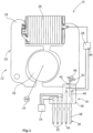
Figure 1 shows a motor vehicleauxiliary unit 10, which in the present embodiment is a gas pump for pumping fuel vapor out of a motor vehicle fuel tank (not shown). Theauxiliary unit 10 comprises an electronically commutatedelectric motor 12, apump wheel 14, asensor element 16 and aunit connector plug 18. - The
electric motor 12 comprises a rotatable permanentmagnetic motor rotor 20 and astatic motor stator 22 with aferromagnetic stator body 24 and asingle stator coil 26. Themotor rotor 20 is co-rotatably connected with thepump wheel 14. In the present embodiment of the invention, thestator body 24 is a laminated stator body which is coated with an electrically isolatingprotection coating 27. Thestator body 24 is provided with anaxial contact opening 46 which in the present embodiment of the invention is provided with a circular cross section and which extends from a statorbody top side 48 along the entire axial height of thestator body 24 to a statorbody bottom side 50. Theelectric motor 12 also comprises amotor electronics 28 being electrically connected to thestator coil 26 for energizing thestator coil 26 for driving themotor rotor 20 and, as a result, for driving thepump wheel 14. - The
unit connector plug 18 comprises aplug housing 30 and is provided with three sensor connector lugs 32, apower connector lug 34 and an external-ground connector lug 36, which are externally electrically contactable. All connector lugs 32,34,36 are stamped out of a single metal sheet and post-processed by a mechanical deformation process. The sensor connector lugs 32 are internally electrically connected with thesensor element 16 for energizing thesensor element 16 and/or for providing a data interface for reading/writing data from/to thesensor element 16. Thepower connector lug 34 is internally electrically connected with themotor electronics 28 and externally connectable to an external energy source, for example to a motor vehicle battery, for providing themotor electronics 28 with electric energy. - The external-
ground connector lug 36 is provided as a single-piece three-way electric connector comprising an external-ground pin 38, a motorelectronics contact element 40 and a statorbody contact element 42. The external-ground pin 38 is externally connectable to an external motor vehicle ground potential. The motorelectronics contact element 40 provides a direct electric connection with themotor electronics 28, in particular with aground terminal 44 of themotor electronics 28. The statorbody contact element 42 provides a direct electric contact with thestator body 24. - In the embodiment of the invention shown in
figures 1 to 3 , the statorbody contact element 42 is provided with a substantially laterally extendingsupport bar 52 and with an arrowhead-shapedcutting element 54. The statorbody contact element 42 is plugged into thecontact opening 46 in that way that thesupport bar 52 is in axial contact with the statorbody top side 48 and that the cuttingelement 54 intrudes into thecontact opening 46. The lateral width of the cuttingelement 54 is slightly larger than the opening diameter of thecontact opening 46 so that the cuttingelement 54 cuts into the sidewalls of thecontact opening 46. In particular, the cuttingelement 54 cuts through theisolation coating 27 of thestator body 24 so that the cuttingelement 54 provides a reliable electric contact with thestator body 24. The cuttingelement 54 also reliably positions the statorbody contact element 42 with respect to thestator body 24 during the assembling process. -
Figure 4 shows an alternative stator body contact element 42' being provided with acontact ring 56. Thecontact ring 56 comprises a substantially axially extendingplug cylinder 58 and asupport flange 60 laterally projecting from theplug cylinder 58. The stator body contact element 42' is plugged into thecontact opening 46 in that way that thesupport flange 60 is in axial contact with the statorbody top side 48 and that theplug cylinder 58 intrudes into thecontact opening 46 and radially contacts the inside surface of thecontact opening 46. Theplug cylinder 58 is provided with an outside diameter being slightly larger than the opening diameter of thecontact opening 46 so that theplug cylinder 58 abrades theisolation coating 27 from the sidewalls of thecontact opening 46 when being inserted into thecontact opening 46. As a result, theplug cylinder 58 provides a reliable electric contact with thestator body 24 and reliably positions the stator body contact element 42' during the assembling process. -
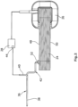
Figures 5 and 6 show another alternative statorbody contact element 42". The statorbody contact element 42" is provided with atransversal contact ring 56", wherein the inside diameter of thecontact ring 56" is substantially equal to the opening diameter of thecontact opening 46. Thecontact ring 56" is provided with three cuttingelements 54" distributed along the outside circumference of thecontact ring 56". The cuttingelements 54" laterally protrude from outside of thecontact ring 56" and extend in axial direction in that way that the cuttingelements 54" axially project over the bottom side of thecontact ring 56". The statorbody contact element 42" is fastened to thestator body 24 by a separate fastening means 62 which in the present embodiment of the invention is a screw with atransversal screw head 64 and an axially extendingscrew pin 66. Thescrew head 64 is in axial contact with the top side of thecontact ring 56". Thescrew pin 66 axially extends from thescrew head 64 through thecontact hole 46 and is threaded into a correspondingnut 68 being located at the bottom side of thestator body 24. By tightening the fastening means 62, thecontact ring 56" is axially pressed against thestator body 24 by thescrew head 64 so that the cuttingelements 54" are pressed into thestator body 24. As a result, the cuttingelements 54" penetrate theprotection coating 27 of thestator body 24 and provide a reliable electric contact with thestator body 24. -
- 10
- motor vehicle auxiliary unit
- 12
- electronically commutated electric motor
- 14
- pump wheel
- 16
- sensor element
- 18
- unit connector plug
- 20
- motor rotor
- 22
- motor stator
- 24
- stator body
- 26
- stator coil
- 27
- protection coating
- 28
- motor electronics
- 30
- plug housing
- 32
- sensor connector lugs
- 34
- power connector lug
- 36
- external-ground connector lug
- 38
- external-ground pin
- 40
- motor electronics contact element
- 42
- stator body contact element
- 44
- ground terminal
- 46
- contact opening
- 48
- stator body top side
- 50
- stator body bottom side
- 52
- support bar
- 54
- cutting element
- 56
- contact ring
- 58
- plug cylinder
- 60
- support flange
- 62
- fastening means
- 64
- screw head
- 66
- screw pin
- 68
- nut
Claims (11)
- Motor vehicle auxiliary unit (10) comprising- an electronically commutated electric motor (12) with• a permanent magnetic motor rotor (20)• a motor stator (22) with a ferromagnetic stator body (24) and at least one stator coil (26), and• a motor electronics (28) with a ground terminal (44), and- a unit connector plug (18) with at least an external-ground connector lug (36) being directly electrically connected with the motor electronics ground terminal (44),- wherein the external-ground connector lug (36) is provided with an integral stator body contact element (42;42':42") that extends to the stator body (24) providing a direct electric connection with the stator body (24).
- Motor vehicle auxiliary unit (10) according to claim 1, wherein a transversal stator body top side (48) is provided with an axial contact opening (46), and
wherein the stator body contact element (42;42') is plugged into the contact opening (46). - Motor vehicle auxiliary unit (10) according to any preceding claim, wherein the stator body (24) is provided with an electrically isolating coating (27), and
wherein the stator body contact element (42;42") is provided with at least one cutting element (54;54") penetrating the stator body coating (27). - Motor vehicle auxiliary unit (10) according to claim 2, wherein the contact opening (46) is substantially circular, and
wherein the stator body contact element (42';42") comprises a contact ring (56;56"). - Motor vehicle auxiliary unit (10) according to claim 4, wherein the inside diameter of the contact ring (56") is substantially equal to the opening diameter of the contact opening (46).
- Motor vehicle auxiliary unit (10) according to claim 4, wherein the contact ring (56) is provided with an axially extending plug cylinder (58) and with a support flange (60) laterally projecting from the plug cylinder (58),wherein the plug cylinder (58) is plugged into the contact opening (46) and radially contacts the inside surface of the contact opening (46), andwherein the support flange (60) is in axial contact with the stator body top side (48).
- Motor vehicle auxiliary unit (10) according to claim 6, wherein the outside diameter of the plug cylinder (58) is slightly larger than the opening diameter of the contact opening (46).
- Motor vehicle auxiliary unit (10) according to any of the claims 4 to 7, wherein the contact ring (56") is provided with several cutting elements (54") distributed along the outside circumference of the contact ring (56").
- Motor vehicle auxiliary unit (10) according to any of the claims 4 to 8, wherein a separate fastening means (62) is provided which extends through the contact ring (56") into the contact opening (46) and axially presses the contact ring (56") against the stator body top side (48).
- Motor vehicle auxiliary unit (10) according to any preceding claim, wherein the unit connector plug (18) comprises at least one power connector lug (34) being electrically connected with the motor electronics (28) for energizing the motor electronics (28).
- Motor vehicle auxiliary unit (10) according to any preceding claim, wherein a sensor element (16) is provided, and
wherein the unit connector plug (18) comprises at least one sensor connector lug (32) being electrically connected with the sensor element (16).
Applications Claiming Priority (1)
| Application Number | Priority Date | Filing Date | Title |
|---|---|---|---|
| PCT/EP2018/075015 WO2020057714A1 (en) | 2018-09-17 | 2018-09-17 | Motor vehicle auxiliary unit |
Publications (2)
| Publication Number | Publication Date |
|---|---|
| EP3853981A1 EP3853981A1 (en) | 2021-07-28 |
| EP3853981B1 true EP3853981B1 (en) | 2023-06-21 |
Family
ID=63637892
Family Applications (1)
| Application Number | Title | Priority Date | Filing Date |
|---|---|---|---|
| EP18772788.8A Active EP3853981B1 (en) | 2018-09-17 | 2018-09-17 | Motor vehicle auxiliary unit |
Country Status (2)
| Country | Link |
|---|---|
| EP (1) | EP3853981B1 (en) |
| WO (1) | WO2020057714A1 (en) |
Family Cites Families (8)
| Publication number | Priority date | Publication date | Assignee | Title |
|---|---|---|---|---|
| EP0026833B1 (en) * | 1979-09-07 | 1982-12-22 | Siemens Aktiengesellschaft | Protective wire connection for motors, especially small size external-rotor motors, and process for its production |
| JP3543881B2 (en) * | 1995-11-08 | 2004-07-21 | 株式会社デンソー | Alternator |
| CN100349357C (en) * | 2003-03-31 | 2007-11-14 | 松下电器产业株式会社 | Motor having highly reliable grounding construction, and electric device having this motor mounted thereon |
| PL2500576T3 (en) * | 2011-03-12 | 2017-02-28 | Grundfos Management A/S | Heat circulation pump |
| DE102012006020A1 (en) * | 2012-03-24 | 2013-09-26 | Minebea Co., Ltd. | Stator for electromotor i.e. inner rotor, has stator body electrical conductively connected with ground contact pin and comprising insertion opening that is extended in axial direction, where ground contact pin is inserted into opening |
| KR101316144B1 (en) * | 2012-06-11 | 2013-10-08 | 뉴모텍(주) | Motor |
| DE102014220201A1 (en) | 2014-10-06 | 2016-04-07 | Bühler Motor GmbH | Electronically commutated DC motor, in particular for an oil pump |
| DE102016223844B4 (en) * | 2016-11-30 | 2022-01-27 | Brose Fahrzeugteile SE & Co. Kommanditgesellschaft, Würzburg | Electric motor and cooling fan module with such an electric motor |
-
2018
- 2018-09-17 WO PCT/EP2018/075015 patent/WO2020057714A1/en unknown
- 2018-09-17 EP EP18772788.8A patent/EP3853981B1/en active Active
Also Published As
| Publication number | Publication date |
|---|---|
| WO2020057714A1 (en) | 2020-03-26 |
| EP3853981A1 (en) | 2021-07-28 |
Similar Documents
| Publication | Publication Date | Title |
|---|---|---|
| CN110771017B (en) | Electric drive unit with housing | |
| JP4774888B2 (en) | motor | |
| US8721306B2 (en) | Pump unit | |
| JP5985043B2 (en) | DC motor for driving automobile units | |
| JP6351750B2 (en) | Control unit and electric power steering apparatus using the same | |
| JP4697597B2 (en) | Busbar and motor | |
| US20130088106A1 (en) | Fluid-sealing electric motor connector and motor | |
| CN107112847B (en) | Electric vehicle accessory | |
| WO2013094086A1 (en) | Motor control unit and brushless motor | |
| KR102566067B1 (en) | Electric machines including brush holding parts and plug modules | |
| JP5691397B2 (en) | Electric pump | |
| US20220085545A1 (en) | Pump unit comprising a connector with pressure compensation element | |
| US20150102693A1 (en) | Electric motor | |
| US6479916B1 (en) | Method and apparatus for mounting electronic motor controls | |
| CN113678346A (en) | Drive device with brushless electric motor | |
| JP5523044B2 (en) | Drive control device and motor unit | |
| JP6736904B2 (en) | Drive | |
| EP3853981B1 (en) | Motor vehicle auxiliary unit | |
| EP1351846B1 (en) | Motor pump unit, particularly a motor vehicle braking device | |
| US9480143B2 (en) | Motor control device | |
| JP2001106097A (en) | Electric power steering system | |
| KR102502184B1 (en) | electric actuator | |
| JP4652925B2 (en) | Motor and motor assembling method | |
| JP4702593B2 (en) | motor | |
| US6945757B2 (en) | Motor pump unit, particularly a motor vehicle braking device |
Legal Events
| Date | Code | Title | Description |
|---|---|---|---|
| STAA | Information on the status of an ep patent application or granted ep patent |
Free format text: STATUS: UNKNOWN |
|
| STAA | Information on the status of an ep patent application or granted ep patent |
Free format text: STATUS: THE INTERNATIONAL PUBLICATION HAS BEEN MADE |
|
| STAA | Information on the status of an ep patent application or granted ep patent |
Free format text: STATUS: THE INTERNATIONAL PUBLICATION HAS BEEN MADE |
|
| PUAI | Public reference made under article 153(3) epc to a published international application that has entered the european phase |
Free format text: ORIGINAL CODE: 0009012 |
|
| STAA | Information on the status of an ep patent application or granted ep patent |
Free format text: STATUS: REQUEST FOR EXAMINATION WAS MADE |
|
| 17P | Request for examination filed |
Effective date: 20210408 |
|
| AK | Designated contracting states |
Kind code of ref document: A1 Designated state(s): AL AT BE BG CH CY CZ DE DK EE ES FI FR GB GR HR HU IE IS IT LI LT LU LV MC MK MT NL NO PL PT RO RS SE SI SK SM TR |
|
| DAV | Request for validation of the european patent (deleted) | ||
| DAX | Request for extension of the european patent (deleted) | ||
| GRAP | Despatch of communication of intention to grant a patent |
Free format text: ORIGINAL CODE: EPIDOSNIGR1 |
|
| STAA | Information on the status of an ep patent application or granted ep patent |
Free format text: STATUS: GRANT OF PATENT IS INTENDED |
|
| INTG | Intention to grant announced |
Effective date: 20230112 |
|
| GRAS | Grant fee paid |
Free format text: ORIGINAL CODE: EPIDOSNIGR3 |
|
| GRAA | (expected) grant |
Free format text: ORIGINAL CODE: 0009210 |
|
| STAA | Information on the status of an ep patent application or granted ep patent |
Free format text: STATUS: THE PATENT HAS BEEN GRANTED |
|
| AK | Designated contracting states |
Kind code of ref document: B1 Designated state(s): AL AT BE BG CH CY CZ DE DK EE ES FI FR GB GR HR HU IE IS IT LI LT LU LV MC MK MT NL NO PL PT RO RS SE SI SK SM TR |
|
| REG | Reference to a national code |
Ref country code: CH Ref legal event code: EP |
|
| REG | Reference to a national code |
Ref country code: DE Ref legal event code: R096 Ref document number: 602018052140 Country of ref document: DE |
|
| REG | Reference to a national code |
Ref country code: AT Ref legal event code: REF Ref document number: 1581623 Country of ref document: AT Kind code of ref document: T Effective date: 20230715 |
|
| REG | Reference to a national code |
Ref country code: IE Ref legal event code: FG4D |
|
| REG | Reference to a national code |
Ref country code: LT Ref legal event code: MG9D |
|
| REG | Reference to a national code |
Ref country code: NL Ref legal event code: MP Effective date: 20230621 |
|
| PG25 | Lapsed in a contracting state [announced via postgrant information from national office to epo] |
Ref country code: SE Free format text: LAPSE BECAUSE OF FAILURE TO SUBMIT A TRANSLATION OF THE DESCRIPTION OR TO PAY THE FEE WITHIN THE PRESCRIBED TIME-LIMIT Effective date: 20230621 Ref country code: NO Free format text: LAPSE BECAUSE OF FAILURE TO SUBMIT A TRANSLATION OF THE DESCRIPTION OR TO PAY THE FEE WITHIN THE PRESCRIBED TIME-LIMIT Effective date: 20230921 |
|
| PGFP | Annual fee paid to national office [announced via postgrant information from national office to epo] |
Ref country code: GB Payment date: 20230921 Year of fee payment: 6 |
|
| REG | Reference to a national code |
Ref country code: AT Ref legal event code: MK05 Ref document number: 1581623 Country of ref document: AT Kind code of ref document: T Effective date: 20230621 |
|
| PG25 | Lapsed in a contracting state [announced via postgrant information from national office to epo] |
Ref country code: RS Free format text: LAPSE BECAUSE OF FAILURE TO SUBMIT A TRANSLATION OF THE DESCRIPTION OR TO PAY THE FEE WITHIN THE PRESCRIBED TIME-LIMIT Effective date: 20230621 Ref country code: NL Free format text: LAPSE BECAUSE OF FAILURE TO SUBMIT A TRANSLATION OF THE DESCRIPTION OR TO PAY THE FEE WITHIN THE PRESCRIBED TIME-LIMIT Effective date: 20230621 Ref country code: LV Free format text: LAPSE BECAUSE OF FAILURE TO SUBMIT A TRANSLATION OF THE DESCRIPTION OR TO PAY THE FEE WITHIN THE PRESCRIBED TIME-LIMIT Effective date: 20230621 Ref country code: LT Free format text: LAPSE BECAUSE OF FAILURE TO SUBMIT A TRANSLATION OF THE DESCRIPTION OR TO PAY THE FEE WITHIN THE PRESCRIBED TIME-LIMIT Effective date: 20230621 Ref country code: HR Free format text: LAPSE BECAUSE OF FAILURE TO SUBMIT A TRANSLATION OF THE DESCRIPTION OR TO PAY THE FEE WITHIN THE PRESCRIBED TIME-LIMIT Effective date: 20230621 Ref country code: GR Free format text: LAPSE BECAUSE OF FAILURE TO SUBMIT A TRANSLATION OF THE DESCRIPTION OR TO PAY THE FEE WITHIN THE PRESCRIBED TIME-LIMIT Effective date: 20230922 |
|
| PGFP | Annual fee paid to national office [announced via postgrant information from national office to epo] |
Ref country code: FR Payment date: 20230918 Year of fee payment: 6 Ref country code: DE Payment date: 20230919 Year of fee payment: 6 |
|
| PG25 | Lapsed in a contracting state [announced via postgrant information from national office to epo] |
Ref country code: FI Free format text: LAPSE BECAUSE OF FAILURE TO SUBMIT A TRANSLATION OF THE DESCRIPTION OR TO PAY THE FEE WITHIN THE PRESCRIBED TIME-LIMIT Effective date: 20230621 |
|
| PG25 | Lapsed in a contracting state [announced via postgrant information from national office to epo] |
Ref country code: SK Free format text: LAPSE BECAUSE OF FAILURE TO SUBMIT A TRANSLATION OF THE DESCRIPTION OR TO PAY THE FEE WITHIN THE PRESCRIBED TIME-LIMIT Effective date: 20230621 |
|
| PG25 | Lapsed in a contracting state [announced via postgrant information from national office to epo] |
Ref country code: ES Free format text: LAPSE BECAUSE OF FAILURE TO SUBMIT A TRANSLATION OF THE DESCRIPTION OR TO PAY THE FEE WITHIN THE PRESCRIBED TIME-LIMIT Effective date: 20230621 |
|
| PG25 | Lapsed in a contracting state [announced via postgrant information from national office to epo] |
Ref country code: IS Free format text: LAPSE BECAUSE OF FAILURE TO SUBMIT A TRANSLATION OF THE DESCRIPTION OR TO PAY THE FEE WITHIN THE PRESCRIBED TIME-LIMIT Effective date: 20231021 |
|
| PG25 | Lapsed in a contracting state [announced via postgrant information from national office to epo] |
Ref country code: SM Free format text: LAPSE BECAUSE OF FAILURE TO SUBMIT A TRANSLATION OF THE DESCRIPTION OR TO PAY THE FEE WITHIN THE PRESCRIBED TIME-LIMIT Effective date: 20230621 Ref country code: SK Free format text: LAPSE BECAUSE OF FAILURE TO SUBMIT A TRANSLATION OF THE DESCRIPTION OR TO PAY THE FEE WITHIN THE PRESCRIBED TIME-LIMIT Effective date: 20230621 Ref country code: RO Free format text: LAPSE BECAUSE OF FAILURE TO SUBMIT A TRANSLATION OF THE DESCRIPTION OR TO PAY THE FEE WITHIN THE PRESCRIBED TIME-LIMIT Effective date: 20230621 Ref country code: PT Free format text: LAPSE BECAUSE OF FAILURE TO SUBMIT A TRANSLATION OF THE DESCRIPTION OR TO PAY THE FEE WITHIN THE PRESCRIBED TIME-LIMIT Effective date: 20231023 Ref country code: IS Free format text: LAPSE BECAUSE OF FAILURE TO SUBMIT A TRANSLATION OF THE DESCRIPTION OR TO PAY THE FEE WITHIN THE PRESCRIBED TIME-LIMIT Effective date: 20231021 Ref country code: ES Free format text: LAPSE BECAUSE OF FAILURE TO SUBMIT A TRANSLATION OF THE DESCRIPTION OR TO PAY THE FEE WITHIN THE PRESCRIBED TIME-LIMIT Effective date: 20230621 Ref country code: EE Free format text: LAPSE BECAUSE OF FAILURE TO SUBMIT A TRANSLATION OF THE DESCRIPTION OR TO PAY THE FEE WITHIN THE PRESCRIBED TIME-LIMIT Effective date: 20230621 Ref country code: CZ Free format text: LAPSE BECAUSE OF FAILURE TO SUBMIT A TRANSLATION OF THE DESCRIPTION OR TO PAY THE FEE WITHIN THE PRESCRIBED TIME-LIMIT Effective date: 20230621 Ref country code: AT Free format text: LAPSE BECAUSE OF FAILURE TO SUBMIT A TRANSLATION OF THE DESCRIPTION OR TO PAY THE FEE WITHIN THE PRESCRIBED TIME-LIMIT Effective date: 20230621 |
|
| PG25 | Lapsed in a contracting state [announced via postgrant information from national office to epo] |
Ref country code: PL Free format text: LAPSE BECAUSE OF FAILURE TO SUBMIT A TRANSLATION OF THE DESCRIPTION OR TO PAY THE FEE WITHIN THE PRESCRIBED TIME-LIMIT Effective date: 20230621 |