EP3853701B1 - Device, use thereof, and system for generating a periodic signal on a capacitive surface sensor - Google Patents
Device, use thereof, and system for generating a periodic signal on a capacitive surface sensor Download PDFInfo
- Publication number
- EP3853701B1 EP3853701B1 EP19773757.0A EP19773757A EP3853701B1 EP 3853701 B1 EP3853701 B1 EP 3853701B1 EP 19773757 A EP19773757 A EP 19773757A EP 3853701 B1 EP3853701 B1 EP 3853701B1
- Authority
- EP
- European Patent Office
- Prior art keywords
- electrically conductive
- conductive structure
- surface sensor
- periodic signal
- electrode grid
- Prior art date
- Legal status (The legal status is an assumption and is not a legal conclusion. Google has not performed a legal analysis and makes no representation as to the accuracy of the status listed.)
- Active
Links
- 230000000737 periodic effect Effects 0.000 title claims description 175
- 238000000034 method Methods 0.000 claims description 24
- 238000012545 processing Methods 0.000 claims description 19
- 230000008569 process Effects 0.000 claims description 12
- 238000009434 installation Methods 0.000 claims description 3
- 230000005484 gravity Effects 0.000 description 25
- 238000013461 design Methods 0.000 description 23
- 230000036961 partial effect Effects 0.000 description 23
- 230000003993 interaction Effects 0.000 description 21
- 230000008859 change Effects 0.000 description 15
- 230000000875 corresponding effect Effects 0.000 description 15
- 230000006870 function Effects 0.000 description 13
- 238000007639 printing Methods 0.000 description 10
- 230000008878 coupling Effects 0.000 description 9
- 238000010168 coupling process Methods 0.000 description 9
- 238000005859 coupling reaction Methods 0.000 description 9
- 239000004020 conductor Substances 0.000 description 7
- 239000000758 substrate Substances 0.000 description 7
- 230000008901 benefit Effects 0.000 description 6
- 238000011156 evaluation Methods 0.000 description 6
- 238000010801 machine learning Methods 0.000 description 6
- 238000004519 manufacturing process Methods 0.000 description 6
- 230000002123 temporal effect Effects 0.000 description 6
- 230000005686 electrostatic field Effects 0.000 description 5
- 239000000463 material Substances 0.000 description 5
- 238000001514 detection method Methods 0.000 description 4
- 230000036962 time dependent Effects 0.000 description 4
- 230000004913 activation Effects 0.000 description 3
- 238000013528 artificial neural network Methods 0.000 description 3
- 230000001419 dependent effect Effects 0.000 description 3
- 230000000694 effects Effects 0.000 description 3
- 238000005516 engineering process Methods 0.000 description 3
- 230000002452 interceptive effect Effects 0.000 description 3
- 230000003340 mental effect Effects 0.000 description 3
- 238000012546 transfer Methods 0.000 description 3
- 238000012795 verification Methods 0.000 description 3
- OKTJSMMVPCPJKN-UHFFFAOYSA-N Carbon Chemical compound [C] OKTJSMMVPCPJKN-UHFFFAOYSA-N 0.000 description 2
- 239000000969 carrier Substances 0.000 description 2
- 125000004122 cyclic group Chemical group 0.000 description 2
- 230000007423 decrease Effects 0.000 description 2
- 239000011888 foil Substances 0.000 description 2
- 238000009472 formulation Methods 0.000 description 2
- 239000004922 lacquer Substances 0.000 description 2
- 239000002648 laminated material Substances 0.000 description 2
- 239000000203 mixture Substances 0.000 description 2
- 238000007645 offset printing Methods 0.000 description 2
- 230000010355 oscillation Effects 0.000 description 2
- 238000004806 packaging method and process Methods 0.000 description 2
- 239000003973 paint Substances 0.000 description 2
- 229920001690 polydopamine Polymers 0.000 description 2
- 230000003068 static effect Effects 0.000 description 2
- 230000007704 transition Effects 0.000 description 2
- 230000001960 triggered effect Effects 0.000 description 2
- 241000895680 Stylosanthes guianensis Species 0.000 description 1
- 230000009471 action Effects 0.000 description 1
- 239000000654 additive Substances 0.000 description 1
- 230000000996 additive effect Effects 0.000 description 1
- 238000004026 adhesive bonding Methods 0.000 description 1
- 229910052799 carbon Inorganic materials 0.000 description 1
- 239000002800 charge carrier Substances 0.000 description 1
- 229920001940 conductive polymer Polymers 0.000 description 1
- 230000001276 controlling effect Effects 0.000 description 1
- 230000002596 correlated effect Effects 0.000 description 1
- 238000011161 development Methods 0.000 description 1
- 238000009826 distribution Methods 0.000 description 1
- 230000008846 dynamic interplay Effects 0.000 description 1
- 230000005684 electric field Effects 0.000 description 1
- 238000001914 filtration Methods 0.000 description 1
- 230000005057 finger movement Effects 0.000 description 1
- 230000007274 generation of a signal involved in cell-cell signaling Effects 0.000 description 1
- 229910021389 graphene Inorganic materials 0.000 description 1
- 238000007646 gravure printing Methods 0.000 description 1
- 239000000976 ink Substances 0.000 description 1
- 238000007641 inkjet printing Methods 0.000 description 1
- 238000007648 laser printing Methods 0.000 description 1
- 239000002923 metal particle Substances 0.000 description 1
- 239000002105 nanoparticle Substances 0.000 description 1
- 238000004080 punching Methods 0.000 description 1
- 230000009467 reduction Effects 0.000 description 1
- 230000002829 reductive effect Effects 0.000 description 1
- 230000003252 repetitive effect Effects 0.000 description 1
- 238000007650 screen-printing Methods 0.000 description 1
- 238000004088 simulation Methods 0.000 description 1
Images


Classifications
-
- G—PHYSICS
- G06—COMPUTING; CALCULATING OR COUNTING
- G06F—ELECTRIC DIGITAL DATA PROCESSING
- G06F3/00—Input arrangements for transferring data to be processed into a form capable of being handled by the computer; Output arrangements for transferring data from processing unit to output unit, e.g. interface arrangements
- G06F3/01—Input arrangements or combined input and output arrangements for interaction between user and computer
- G06F3/03—Arrangements for converting the position or the displacement of a member into a coded form
- G06F3/041—Digitisers, e.g. for touch screens or touch pads, characterised by the transducing means
- G06F3/0416—Control or interface arrangements specially adapted for digitisers
- G06F3/04166—Details of scanning methods, e.g. sampling time, grouping of sub areas or time sharing with display driving
-
- G—PHYSICS
- G06—COMPUTING; CALCULATING OR COUNTING
- G06F—ELECTRIC DIGITAL DATA PROCESSING
- G06F3/00—Input arrangements for transferring data to be processed into a form capable of being handled by the computer; Output arrangements for transferring data from processing unit to output unit, e.g. interface arrangements
- G06F3/01—Input arrangements or combined input and output arrangements for interaction between user and computer
- G06F3/03—Arrangements for converting the position or the displacement of a member into a coded form
- G06F3/033—Pointing devices displaced or positioned by the user, e.g. mice, trackballs, pens or joysticks; Accessories therefor
- G06F3/039—Accessories therefor, e.g. mouse pads
- G06F3/0393—Accessories for touch pads or touch screens, e.g. mechanical guides added to touch screens for drawing straight lines, hard keys overlaying touch screens or touch pads
-
- G—PHYSICS
- G06—COMPUTING; CALCULATING OR COUNTING
- G06F—ELECTRIC DIGITAL DATA PROCESSING
- G06F3/00—Input arrangements for transferring data to be processed into a form capable of being handled by the computer; Output arrangements for transferring data from processing unit to output unit, e.g. interface arrangements
- G06F3/01—Input arrangements or combined input and output arrangements for interaction between user and computer
- G06F3/03—Arrangements for converting the position or the displacement of a member into a coded form
- G06F3/041—Digitisers, e.g. for touch screens or touch pads, characterised by the transducing means
- G06F3/044—Digitisers, e.g. for touch screens or touch pads, characterised by the transducing means by capacitive means
- G06F3/0442—Digitisers, e.g. for touch screens or touch pads, characterised by the transducing means by capacitive means using active external devices, e.g. active pens, for transmitting changes in electrical potential to be received by the digitiser
Definitions
- the invention relates to a device and a system for generating a periodic signal on a capacitive area sensor, as well as the use of the device for generating a periodic signal on a capacitive area sensor.
- the device is formed by a three-dimensional object, on at least the underside of which an electrically conductive structure is arranged.
- the system includes such a device, as well as a capacitive area sensor, whereby the device can be used to generate periodic signals on the area sensor.
- WO 2011 154524 A1 a system for transmitting information from an information carrier to a capacitive surface sensor is described.
- the information carrier has an electrically conductive layer on an electrically non-conductive substrate, the electrically conductive layer being designed as a “touch structure” and comprising at least one touch point, a coupling surface and/or a conductor track.
- the touch points replicate the properties of fingertips.
- the use of the system and a method for acquiring information are described, which is based on a static or dynamic interaction between the surface sensor and the information carrier. Fig.
- the WO 2011 154524 A1 shows a variant of the interaction in which the device having the area sensor is moved over the information carrier and the complete information on the information carrier gradually becomes readable.
- the document reveals the coding of the information, which is based in particular on the positions of the sub-areas.
- WO 2012 072648 A1 describes a method for capturing information from an information carrier using a capacitive touchscreen.
- the information carrier described essentially consists of two different materials that differ in terms of conductivity or dielectric coefficient.
- a relative movement between the information carrier and the touchscreen causes an interaction between the information carrier and the surface sensor, which is based on the different material properties and generates a touch signal.
- the electrically conductive pattern includes the basic elements touch points, coupling surface and conductor tracks, with the conductor tracks connecting the touch points to one another and/or to the coupling surface.
- WO 2016 131963 A1 describes a capacitive information carrier that includes first and second electrically conductive areas that are at least partially connected to one another. At least two subregions of the first electrically conductive region cover at least two different intersection points of transmitting and receiving electrodes of the touchscreen.
- WO 2018 141478 A1 describes a method for generating a time-dependent signal on a capacitive surface sensor, the conductive structure of which consists of many individual elements and the time-dependent signal is generated by a relative movement between an input device and the card-like object.
- WO 2018 141479 A1 discloses a device for generating a time-dependent signal on a capacitive area sensor. Both applications necessarily provide for an input means which is in dynamic active contact with the electrically conductive structure. The need for an input device can be disadvantageous for certain applications.
- the object of the present invention is to provide a device and a system for generating a periodic signal on a capacitive surface sensor that does not have the disadvantages and shortcomings of the prior art. Furthermore, the device to be provided should produce a periodic signal on the surface sensor without the need for an additional input means. Another object underlying the invention is to provide a particularly user-friendly interactive device that can be used for verification, authentication and/or identification purposes.
- a device for generating a periodic signal on a capacitive surface sensor comprising an electrically conductive structure which is arranged on a non-conductive substrate.
- the device is characterized in that the device is a three-dimensional object, the three-dimensional object having a bottom side, the electrically conductive structure being arranged at least on the bottom side of the three-dimensional object and determining the course of a periodic signal.
- the invention relates to a device for generating a periodic signal on a capacitive surface sensor with an electrode grid comprising rows and columns, the device being a three-dimensional object, the three-dimensional object having a contact surface, an electrically conductive structure at least on the contact surface of the three-dimensional Object is arranged and wherein the electrically conductive structure and the surface sensor are set up such that when the device moves relative to the surface sensor along the direction of a row or a column of the electrode grid, a periodic signal is generated which oscillates orthogonally to the movement of the device.
- the invention relates to a system comprising the device and a device with an area sensor.
- the inventors have found that there is a connection between the specific structure of the electrically conductive elements on the device or their arrangement relative to one another and the way in which a periodic signal runs on the surface sensor when the device moves relative to each other.
- the signal is preferably understood to be the spatial course of the input on a touch surface or a screen of a surface sensor, which the surface sensor or its touch controller perceives.
- the contact surface preferably refers to that outer surface of a surface sensor which is intended for input in the form of a touch. In the case of a touchscreen as an area sensor, the touch surface is the screen.
- this movement of the finger is detected by the surface sensor as a spatial signal, the course of this spatial signal essentially corresponding to or corresponding to the course of the finger movement.
- This movement of the user finger or the signal perceived by the surface sensor can be recorded by the surface sensor, for example, in a coordinate system with two axes (and possibly displayed on a screen), which corresponds to mathematical customs with an x-axis for the horizontal axis and a y-axis for the vertical axis.
- a change in the x coordinate therefore preferably corresponds to a shift of a point to the right or left, while a change in the y coordinate of a point corresponds to a shift up or down.
- the movement perceived and detected by the surface sensor does not necessarily correspond to the movement of the device on the touch surface or the screen, but rather the detected signals are due to the electrical conductive structure changes compared to the actual movement of the device, this change in the sense of the invention is preferably referred to as deviation or distortion. It is a significant merit of the present invention that with the proposed device an input can be made on a capacitive surface sensor without the use of a special input means being necessary.
- the advantages that result from the fact that the input means can be dispensed with are, for example, that the user no longer has to use his finger to make an entry on the surface sensor. This may be desirable, for example, because it makes the device easier to use.
- the user can hold the device containing the area sensor in one hand and guide the device over the area sensor with the other hand.
- the way of using the device is advantageous because it is very intuitive for the user to bring the device and the device together in this simple way.
- Not using an input device can also be an advantage because it prevents input devices, such as stylos or special pens, from being forgotten or lost.
- the use of the device is made easier in particular by the fact that, in the context of the present invention, the device "simply” has to be pulled over the area sensor, without this pulling movement having to be connected to any input means or the like must be accompanied, followed or supported.
- the pulling movement of the three-dimensional object is preferably also referred to as a “relative movement” between the device and the surface sensor.
- the device according to the invention advantageously enables a particularly intuitive and user-friendly interactive object, which can be verified and/or identified with the aid of a capacitive area sensor.
- an xy coordinate system is mentally placed on a touch surface or the screen of a surface sensor, different courses result for the actual movement of the device and the signals detected by the surface sensor, the deviations being due in particular to the presence of the electrically conductive structure can be attributed.
- the orientation of the xy coordinate system preferably corresponds to the orientation of an electrode grid of the area sensor.
- the inventors have recognized that when a relative movement is carried out between a device that has a suitable electrically conductive structure and a surface sensor, a periodic signal is generated, which is expressed in the mental xy coordinate system described above, in particular as a wobble, loop or zigzag pattern expresses. In other words, what is detected by the area sensor “oscillates”. Signal around a fixed center position, with the downward or upward deviations called "amplitudes".
- the device moves relative to the surface sensor along the direction of a row or a column of the electrode grid.
- the electrical structure is set up or configured in such a way that the surface sensor detects a periodic signal which oscillates orthogonally to the movement of the device.
- the terms "oscillate”, “oscillate” or “wobble” are used synonymously with one another.
- the mental coordinate system can be placed on the screen of the area sensor in such a way that the x-axis of the coordinate system coincides with the fixed central position around which the periodic signal fluctuates.
- the course of the periodic signal can then advantageously be represented as a function x(y), it being preferred in the sense of the invention that this function x(y) has a periodicity.
- the y-direction preferably corresponds to the movement of the device, while the x-direction defines a direction orthogonal to this, in which the signal oscillates about a central position.
- the periodic signal has a periodicity in terms of time.
- the x and/or y coordinates of the periodic signal can each be represented as a function of time, that is, as a function of the X coordinate x(t) and as a function of the Y coordinate of the periodic signal y( t).
- the periodic signal represents a temporally periodic change in size, while in the case described above it represents a spatially periodic change in size, in which spatially varying sizes are preferably described.
- the periodic signal that is generated in the context of the present invention is also time-dependent.
- the representations of the periodic signal can be converted into one another as a spatially or temporally periodic change.
- the y coordinate preferably defines the course of movement of the device on the surface sensor.
- the t coordinate preferably defines the time course during the movement of the device on the surface sensor. Knowing y(t) so the The two representations can be converted into one another based on the temporal movement of the device on the surface sensor.
- the temporal periodicity is preferably characterized by the period length of the signal.
- it is a dynamic signal, which in the sense of the present invention means in particular that the periodic signal changes while the device is moved over the surface sensor, i.e. during the relative movement between the electrically conductive structure and the surface sensor.
- the electrically conductive structure acts as a signal generator or functions as such.
- the electrical structure is preferably set up in such a way that when the device moves relative to the surface sensor, a periodic signal is generated which oscillates orthogonally to the movement of the device.
- the course of the periodic signal is influenced or determined in particular by the center of gravity of the electrically conductive structure or by partial areas of the electrically conductive structure. It is particularly preferred that the center of gravity of partial areas interacts with the electrode grid of the capacitive surface sensor. In other words, it may be particularly preferred that the center of gravity overlaps with selected electrode intersections and thus interacts at this point.
- the center of gravity of the electrically conductive structure can be formed, for example, by the geometric center of gravity of the surface covered by the electrically conductive structure. It can also be preferred that each sub-element forms a center of gravity together with the main element.
- the center of gravity of the electrically conductive structure is influenced by the mass distribution and/or surface coverage of the electrically conductive material that forms the electrically conductive structure, so that a weighted center of gravity of the electrically conductive structure can be determined.
- the electrically conductive structure has at least two subregions with two centers of gravity, which are designed to generate a touch event when superimposed with an intersection of the electrode grid and, in the case of no superimposition to an intersection of the electrode grid, not to assign a touch event generate, so that during a relative movement of the device along a row or column of the electrode grid, a periodic signal is generated by alternating generation of a touch event with alternating superimposition of the first or second center of gravity with intersections of the electrode grid.
- the center of gravity is preferably a geometric center of gravity that can be determined in relation to a partial area. If the center of gravity of that partial area overlaps with an electrode crossing of the area sensor the electrode crossing is preferably covered by a sufficient proportion or area of the electrically conductive structure so that a touch event is triggered.
- the detection of touch events in capacitive surface sensors is based on a capacitive interaction, with commercial surface sensors, in particular touch screens, being optimized for the detection of fingertips.
- a touch event should only be generated by the surface sensor when a sufficient capacitive interaction with its electrode grid is recorded, which suggests a finger touch.
- the touch points In the state of the art, such as WO 2011 154524 A1 , the knowledge was exploited to recreate fingertips with conductive touch points.
- the touch points should preferably have a sufficient size (preferably with a diameter of 8 mm or more) and/or be additionally capacitively charged by coupling an external capacitance (for example a hand). .
- the electrically conductive structure according to the invention preferably does not provide any such touch points. Instead, the preferably present at least two partial areas with two different centers of gravity should not be detected as two touch events whenever they are positioned on an area sensor. In particular, the two center of gravity should not lead to stable touch events, so that a movement of the device via the area sensor is detected as a continuous touch move.
- the partial areas of the electrically conductive structure do not completely fill an area that corresponds to an electrode crossing (for example 5 x 5 mm). Rather, it is preferred that the partial areas have an extent that spans two, four or more electrode intersections, but without completely filling the area of two, four or more electrode intersections.
- the partial areas are designed in such a way that at a position in which the center of gravity does not overlap with an electrode intersection, a sufficient area is not covered with electrically conductive material on any electrode intersection in order to trigger a touch event.
- the essential area portions of the partial area of the structure be divided into at least two electrode intersections, so that there is no sufficient capacitive interaction for the electrode intersection to trigger a touch event.
- the at least two partial areas with the two centers of gravity can preferably be arranged at a distance of one row or column of the electrode grid (or an integer multiple thereof), it being particularly preferred that the centers of gravity are at different heights in the intended direction of movement of the device.
- Fig. 7 shows an example of an electrically conductive structure with a linear main element and a linear left sub-element, which is arranged at an angle relative to the main element.
- the sub-element and main element in the left area can be mentally divided into two sub-areas with respect to the underlying electrode grid, which have different centers of gravity.
- a touch event is generated in a left or right column, depending on which centroid overlaps with the electrode intersection.
- a touch event is generated in a left or right column when the respective electrode intersection of the underlying electrode grid is covered or overlapped by a minimum area of the electrically conductive structure.
- This relative minimum area is preferably >20% of the area of an electrode intersection and particularly preferably >30% of the area of an electrode intersection.
- Electrically conductive structures with a linear shape have proven to be particularly preferred.
- the electrically conductive structures are preferably formed by a continuous line, wherein the line can preferably have angles and/or curves.
- the linear shape preferably has a width of 0.5 mm to 8 mm, preferably 1.5 mm to 5 mm, particularly preferably 1.5 mm to 3 mm.
- the electrically conductive structure does not include any subareas that have an extent of 8 mm x 8 mm or more.
- touch events can always be triggered due to the extent, preferably regardless of an overlap of a center of gravity with an electrode crossing.
- the electrically conductive structure is designed in such a way that At any time when the device moves over the capacitive surface sensor, it does not completely cover or overlap any of the electrode crossings of the underlying electrode grid.
- the preferred relative maximum area is ⁇ 70% of the area of an electrode intersection and particularly preferably ⁇ 50% of the area of an electrode intersection.
- a line shape can be used in a particularly effective way to cause the generation of touch events to depend on a relative position to the electrode crossings and thus a described generation of an oscillating signal.
- the electrically conductive structure can additionally be characterized by the design of at least one sub-element.
- the term design includes, but is not limited to, the shape, size, geometry, length, width, orientation, position and angle of the element of the electrically conductive structure.
- Preferred design variants include, for example, line-shaped main and/or partial elements that are characterized by length, width and angle.
- the sub-elements are galvanically connected to the main element and form the electrically conductive structure as a whole.
- the electrically conductive structure is designed to be open, i.e. has open ends or, in other words, is characterized by a beginning and an end and/or is not connected to form a ring or a similar self-contained figure or geometry.
- the electrically conductive structure comprises at least one linear main element and at least one linear partial element, the main element and the partial element being galvanically connected to one another and preferably enclosing an angle of 10° to 80°, particularly preferably 20° to 60° .
- the main element can, for example, have a length of 20 mm to 60 mm, while the sub-element has a length of 5 mm to 20 mm.
- the main and partial elements are preferably straight-line structures. It may also be preferred to position two sub-elements at different ends of the main element.
- electrical structures with sub-elements angled in this way are particularly characterized by generating periodic signals when the device is moved according to the invention via a surface sensor.
- the contact surface has a substantially rectangular shape, with the main element having an angle of 5° to 45°, preferably 10° to 35°, to one of the two edges of the contact surface.
- Such a rectangular shape is present, for example, in cuboid packaging or a flat rectangular card.
- a user will place the device on a surface sensor in such a way that the edge of the rectangle is aligned with an edge of a, usually, rectangular surface sensor, with movement preferably taking place along the horizontal or vertical of the surface sensor.
- the alignment of the angle of the main element to the edge of the contact surface therefore preferably determines the orientation of the main element when using the device on a surface sensor.
- the aforementioned angles can be used to bridge two electrode crossings in a particularly effective manner, whereby depending on the positioning of two sub-elements at different heights, a described oscillation is caused and a periodic signal is therefore generated.
- the periodic signal can be assigned a period length as a characterizing quantity of the periodic signal, the period length preferably corresponding to the reciprocal of the spatial frequency at which the periodic signal fluctuates.
- the period length is determined by the arrangement and/or design of the electrode grid of the surface sensor. It was particularly surprising that the spatial frequency of the periodic signal correlates with the grid constant of the electrode grid of the area sensor. In other words, in the context of the invention, it is preferred that the spatial or local periodicity of the periodic signal is determined by the arrangement and/or design of the electrode grid of the surface sensor.
- the period length of the periodic signal is determined by the geometry of the electrode grid in the capacitive surface sensor, the arrangement and/or design of the electrode grid of the surface sensor preferably also being referred to as the “geometry of the electrode grid”.
- the period length of the signal reflects the arrangement of the electrodes in the electrode grid of the surface sensor.
- the period length of the signal is between 2 and 9 mm.
- the period length of the signal correlates with the geometry of the electrode grid, in particular with the grid constant.
- the grid constant in capacitive area sensors is preferably in the range between 2 and 9 mm.
- the period length is preferably at least 3 mm and a maximum of 7 mm, since this range is surprisingly similar to the grid constant of capacitive area sensors, especially for mobile phones, Smartphones, tablets or comparable devices are correlated.
- the period length of the signal is between 4 and 5 mm.
- a corresponding grid constant in capacitive area sensors is particularly suitable for reliably detecting finger inputs on capacitive area sensors. Many devices that contain a capacitive surface sensor have a corresponding grid constant. It was particularly surprising that the periodic signals have a period length between 4 and 5 mm. The inventors have surprisingly succeeded in gaining conclusions about the geometry of the electrode grid by evaluating the period length of the periodic signals.
- the periodic signal can also be assigned a period duration as a characterizing variable of the periodic signal, the period duration preferably corresponding to the reciprocal of the frequency at which the periodic signal fluctuates.
- the period duration i.e. the temporal periodicity of the periodic signal
- the x and/or y coordinates of the periodic signal can each be represented as a function of time, that is, as a function of the X coordinate x(t) and as a function of the Y coordinate of the periodic signal y( t).
- the periodic signal has a period of at least 25 ms and particularly preferably of at least 50 ms. It is furthermore particularly preferred that the periodic signal has a period duration of a maximum of 1 s and particularly preferably of a maximum of 500 ms.
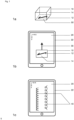
- the device or the three-dimensional object is formed by packaging or a folding box. It is further preferred that the three-dimensional object is referred to as an “object” for short.
- the object is preferably a cuboid structure that has a height, a width and a length.
- the object has six side surfaces.
- the side surface of the object that faces the surface sensor is preferably referred to as the underside of the object.
- the surface of the object that faces the surface sensor is alternatively referred to as the contact surface and does not necessarily have to be the underside of the object in relation to the intended use of the object.
- the underside and contact surface are used synonymously and here refer to the function of this surface to be suitable for interacting with the capacitive surface sensor.
- the side surface of the object that lies opposite the bottom is preferably referred to as the top of the object.
- the remaining four surfaces of the object are preferably referred to as side surfaces.
- the formulation that the electrically conductive structure is arranged at least on the underside of the three-dimensional object preferably means in the sense of the invention that the electrically conductive structure is in any case on the underside of the object and, in a preferred embodiment of the invention, only there.
- the entire electrically conductive structure in this preferred embodiment of the invention is on the underside or contact surface of the device.
- it is particularly preferred that the entire electrically conductive structure is suitable for interacting with the electrode grid of the capacitive surface sensor.
- the electrically conductive structure is arranged essentially completely on the underside of the object.
- the electrically conductive structure is arranged on the inside of the underside of the three-dimensional object, for example a folding box.
- the electrically conductive structure can be optically hidden by a paint layer and/or a lacquer layer and/or by a laminate material so that the electrically conductive structure is not visible to the user.
- the interaction between the electrically conductive structure and the capacitive surface sensor is preferably a capacitive interaction, i.e. there is no direct galvanic contact between the electrically conductive structure and the surface sensor.
- the shape of the object is not limited to cuboid or cube-shaped geometries.
- Other shapes for example cylinders, tetrahedrons or other shapes or bodies also represent possible embodiments.
- individual elements or partial areas of the electrically conductive structure are also, ie additionally, present on one side surface or several side surfaces of the object.
- at least part of the electrically conductive structure is suitable for interacting with the electrode grid of the capacitive surface sensor.
- a contact surface can be arranged on one of the side surfaces of the device or of the three-dimensional object.
- a contact surface is a partial element of the electrically conductive structure, which is designed in such a way that it is conductively connected to the electrically conductive structure, so that touching the contact surface of the electrically conductive structure causes a change in potential of the system consisting of electrically conductive structure and surface sensor caused is, whereby this potential change can preferably be detected by the surface sensor.
- the term contact surface is used synonymously with contact surface.
- the width and length of the object are significantly greater than the height of the object.
- Such an object can be described, for example, as a card-shaped object and is characterized by the fact that it represents a substantially flat object. It may further be preferred that the flat object is flexible and/or bendable.
- the side surface of the object that faces the area sensor is preferably referred to as the bottom of the object, while the side surface of the object that faces the bottom is referred to as the top of the object.
- the remaining four side surfaces are preferably referred to as side surfaces.
- the formulation that the electrically conductive structure is arranged at least on the underside of the three-dimensional object preferably means in the sense of the invention that the electrically conductive structure is in any case on the underside of the object and, in a preferred embodiment of the invention, only there.
- the entire electrically conductive structure in this preferred embodiment of the invention is on the underside of the device.
- the entire electrically conductive structure is suitable for interacting with the electrode grid of the capacitive surface sensor. This is preferably achieved in that the electrically conductive structure is arranged essentially completely on the underside of the object.
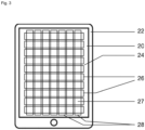
- Area sensors in particular include at least one active circuit, which is preferably referred to as a touch controller, which can be connected to a structure of electrodes.
- this electrode structure is preferably also referred to as an “electrode grid”.
- Area sensors are known in the prior art, the electrodes of which comprise groups of electrodes that differ from one another in their function, for example. These can be, for example, transmitting and receiving electrodes, which can be arranged in a particularly preferred arrangement in the form of columns and rows, that is to say in particular form nodes or intersections at which at least one transmitting and one receiving electrode cross each other or overlap.
- the crossing transmitting and receiving electrodes in the area of the nodes are aligned with one another in such a way that they essentially enclose a 90° angle with one another.
- an electrostatic field that reacts sensitively to changes is formed between the transmitting and receiving electrodes of the surface sensor.
- These changes can occur, for example, by touching the surface of the area sensor with a finger or a conductive object, by touching a contact or grip surface of an electrically conductive structure that is at least partially located on the area sensor, or in particular by bringing the area sensor into contact with an electrically conductive structure, which is arranged, for example, on the underside of a device.
- such changes lead to potential changes within the electrostatic field, which are preferably caused by the electric field between transmitting and receiving electrodes being locally reduced, for example by touching a contact surface of an electrically conductive structure.
- Such a change in the potential conditions is detected and further processed by the electronics of the touch controller.
- the touch controller preferably controls the electrodes in such a way that a signal is transmitted between one or more transmitting electrodes and one or more receiving electrodes, which is preferably an electrical signal, for example a voltage, a current strength or a potential (difference) can act.
- a signal is transmitted between one or more transmitting electrodes and one or more receiving electrodes, which is preferably an electrical signal, for example a voltage, a current strength or a potential (difference) can act.
- These electrical signals in a capacitive surface sensor are preferably evaluated by the touch controller and processed for the device's operating system.
- the information transmitted from the touch controller to the operating system describes so-called individual “touches” or “touch events”, which can be imagined as individual recognized touches or can be described as individual inputs.
- These touches are preferably characterized by the parameters “x coordinate of the touch”, “y coordinate of the touch”, “time stamp of the touch” and “type of touch”.
- the “x and y coordinate” parameters describe the position of the input on the touchscreen. Each pair of coordinates is preferably assigned a time stamp that describes when the entry took place at the corresponding location.
- the “Touch event type” parameter describes the detected state of the input on the touchscreen.
- the types Touch Start, Touch Move, Touch End and Touch Cancel are known to those skilled in the art. With the help of the parameters Touch Start, at least one Touch Move and Touch End as well as the associated coordinates and time stamps, a touch input can be described on the capacitive surface sensor. It is preferred and known in the prior art as multi-touch technology that multiple touch inputs can be evaluated at the same time.
- the periodic signal preferably comprises a number of such touches or touch inputs, with properties of the signal preferably depending on the specific shape of the electrically conductive structure, as well as on the structural arrangement of the transmitting and receiving electrodes of the surface sensor.
- the periodic signal is formed by a set of touches and/or touch inputs that have recurring properties and/or periodicity in spatial and/or temporal terms.
- the course of the periodic signal is determined by the electrically conductive structure.
- Projected capacitance touch technology PCT is an exemplary technology that allows multi-touch operation.
- the amount of touch events or touches is preferably processed and evaluated with the help of a software program ('app').
- the evaluation can include several steps.
- the device parameters of the device containing the area sensor for example the resolution of the touchscreen, are first determined.
- the signal comprising a number of touch events is preferably pre-filtered in the next step and specific characteristics of the signal are amplified or adjusted.
- the signal is then checked for plausibility by calculating parameters such as the time course of the signal, speed and data density, checking for possible manipulation and comparing them with known threshold values.
- various characteristic values and parameters of the signal are then determined or calculated, including the characteristic values start of the signal, end of the signal, local maxima and minima, local velocities of the signal, deflection, amplitudes, period length of periodic signals and possibly others Features to convert the signal into a comparable data set. It is particularly preferred to then compare this data set with other data sets and to assign it to a known data set, for example in a database, and thus to decode the signal. In a further preferred embodiment, the data set is compared using a machine learning model ( artificial neural networks ) previously created from recordings. It was particularly surprising that the use of a machine learning model to decode the signal is particularly suitable for complex signals with many different parameters.
- the decoding of the signal preferably includes an assignment of the detected periodic signal to a known electrically conductive structure or an identification code represented thereby.
- the periodic signal generated by the relative movement of the electrical structure on the surface sensor is particularly tamper-proof. Imitation of the complex periodic signal with another electrically conductive structure (i.e. without presenting the identification code) is almost impossible.
- the device or the system is therefore particularly suitable for authentication procedures, for example to grant a user access to information or an action when the device is placed on a mobile terminal and the movement according to the invention is carried out via the surface sensor.
- the term “capacitive surface sensor” preferably refers to devices having touch sensors that are able to perceive external influences or influences, for example contacts, on the surface of the touch sensor and to evaluate them using attached logic. Such area sensors are used, for example, to make machines easier to operate. In addition to touch sensors, which are primarily used for input, there are touchscreens that are also display and/or output devices. In order to make an input on a capacitive screen, which is also preferably referred to as a touch screen, touch screen or surface sensor, special input pens or similar devices can be used in addition to the fingers. For the purposes of the invention, fingers and special input pens are preferably summarized under the term input means. These are preferably able to change an electrostatic field between row and column electrodes within the area sensor.
- the capacitive, preferably touch-sensitive screen is preferably set up to detect the position of the finger or stylus.
- Area sensors are usually provided in an electronic device, which can be smartphones, cell phones, displays, tablet PCs, tablet notebooks, touchpad devices, graphics tablets, televisions, PDAs, MP3 players, trackpads and/or capacitive input devices, without being limited to that.
- device containing an area sensor or “device with an area sensor” preferably refers to electronic devices, such as those mentioned above, which are able to further evaluate the information provided by the capacitive area sensor. In preferred embodiments, these are mobile devices.
- Touch screens are also preferably referred to as touch screens, surface sensors or touch screens.
- An area sensor does not necessarily have to be used in conjunction with a display or touchscreen.
- the area sensor is integrated visibly or non-visibly in devices, objects and/or devices.
- the electrically conductive structure in the context of the present invention does not have to be activated by a user by touching a portion of the structure, but that the surface sensor also detects the device or its electrically conductive structure in this way, that is, without touching it and/or or activation.
- the invention represents a significant deviation from the known state of the art, since experts had previously assumed that activation of an electrically conductive structure, for example by touching a user, was required in order to be recognized by the capacitive surface sensor.
- the present invention now discloses a device and a system in which an input means for generating a periodic signal can surprisingly be dispensed with.
- the surface sensor is enabled to detect the electrically conductive structure of the device without the structure being activated by a user touch is advantageously based on a coupling between the capacitive surface sensor and the electrically conductive structure, which exists in particular when the electrically conductive structure with at least two rows and at least two columns, or at least two transmitting electrodes and at least two receiving electrodes, of the electrode grid of the capacitive surface sensor interacts.
- the electrically conductive structure overlaps with at least two electrode intersections. An exchange of charge carriers can then occur between the surface sensor, or its electrodes, and the electrically conductive structure.
- the electrically conductive structure on the three-dimensional object causes the electrodes of the electrode grid in the surface sensor to interact with one another indirectly via the electrically conductive structure.
- the electrically conductive structure is designed to bridge a distance between the at least two transmitting and receiving electrodes. In this way, a capacitive connection is preferably created between at least two different electrode intersections, which is produced and held in particular by the electrically conductive structure.
- the electrically conductive structure connects the columns and rows of the electrode grid of the surface sensor with one another, so that an interaction between the at least four affected electrodes (two transmitting electrodes and two receiving electrodes) is caused here.
- the electrically conductive structure is designed to bring about bridging and/or connections of electrode crossings within the electrode grid of the surface sensor.
- the connection and/or bridging of the electrode crossings is preferably based on a capacitive interaction, which is also referred to as capacitive coupling.
- the connection and/or bridging is not based on a galvanic connection, but on a capacitive connection. This can advantageously lead to a self-induced signal generation, in particular to a generation of the desired periodic signal when the device moves via the capacitive surface sensor.
- the electrically conductive structure comprises at least one main element. In a further preferred embodiment, the electrically conductive structure comprises at least one sub-element in addition to the main element. Main element and one or more sub-elements are galvanically connected to one another and form the electrically conductive structure as a whole.
- the electrically conductive structure can be characterized by the design of the main element and the design of the sub-elements. For the purposes of the invention, the term design includes, but is not limited to, the shape, size, geometry, length, width, orientation, position and angle of the element of the electrically conductive structure.
- Main and/or sub-elements can be, for example, linear, circular or arcuate without being limited to this.
- the transition between the sub-element and the main element can also be flowing or arcuate. It may also be preferred to electrically connect a sub-element to another sub-element instead of the sub-element.
- the number, arrangement and orientation of the sub-elements is not limited to the variants described.
- the entirety of the main and sub-elements that are galvanically connected to one another is referred to as an electrically conductive structure. It can also be preferred that there are two or more electrically conductive structures on a contact surface of the object, which are characterized in that they are not galvanically connected to one another.
- the electrically conductive structure interacts with the electrode grid of the capacitive area sensor.
- different electrode crossings interact with the electrically conductive structure or one or more centroids of the electrically conductive structure.
- An electrode crossing interacts with the electrically conductive structure in particular when the electrically conductive structure overlaps selected electrode crossings at a time x.
- the center of gravity of the electrically conductive structure interacts with the capacitive surface sensor or the electrode grid. At points where the center of gravity of the electrically conductive structure overlaps with the electrode intersections, the capacitive surface sensor is activated or, in other words, a touch event is generated.
- the electrically conductive structure or the center of gravity gradually interacts with other electrode intersections. This results in a superposition of two different geometries: on the one hand, the geometry of the electrode grid and, on the other hand, the geometry of the electrically conductive structure. If these two geometries are moved relative to each other, the two geometries overlap. This overlay repeats itself cyclically or periodically. This leads to periodically arranged touch events on the capacitive surface sensor, which then form the periodic signal as a whole. Similar effects are known to experts in optics under the term interference. It was completely surprising that an electrically conductive structure enters into such an interaction with the capacitive surface sensor.
- the electrically conductive structure interacts with at least two rows and at least two columns at all times of movement. It is particularly preferred that the two columns and/or two rows are not adjacent. In other words, it is preferred that the electrically conductive structure connects or bridges two spaced-apart rows and/or two spaced-apart columns.
- this connection between different electrode crossings or the transmitting and receiving electrodes of the electrode grid makes the activation of the electrically conductive structure by the touch of a user obsolete, so that in the context of the present invention, surprisingly, the use of one Input means, such as a user's finger, can be dispensed with.
- the advantageous effects and technical effects of the invention are preferably based on the interaction between the electrically conductive structure and the surface sensor, particularly preferably between the electrically conductive structure and the electrode grid of the surface sensor and most preferably between the electrically conductive structure and the columns and rows or the Transmitting and receiving electrodes of the electrode grid of the surface sensor.
- this interaction preferably leads to a change in the electrostatic field between the electrodes in a surface sensor and/or to a measurable change in the capacitance.
- the change in the electrostatic field can be brought about in particular by a relative movement between the surface sensor and the three-dimensional object.
- the periodic signal is generated by a relative movement between the electrically conductive structure and the surface sensor.
- this relative movement can preferably also be referred to as a dynamic active contact.
- the duration of the relative movement determines the duration of the periodic signal.
- duration means in particular the total duration of the signal.
- the periodic signal has a duration of at least 250 ms, preferably at least 500 ms and particularly preferably at least 750 ms.
- the present invention also departs from the prior art in that a touch structure on the device is no longer required to generate a signal on the area sensor.
- a touch structure requires a specific spatial structure of predefined elements of an electrically conductive structure, namely in particular a touch point, a coupling surface and line means for connection.
- the presence of these predefined elements and their functionalities is not required in the context of the present invention, nor is the need to recreate or imitate the properties of fingertips with the electrically conductive structure.
- the proposed device does not require a special coupling surface that must be touched by a user in order to activate the electrically conductive structure for the surface sensor.
- Area sensors are usually provided in an electrical device, which can be smartphones, cell phones, displays, tablet PCs, tablet notebooks, touchpad devices, graphics tablets, televisions, PDAs, MP3 players, trackpads and/or capacitive input devices, without being limited to that.
- Touch screens are also preferably referred to as touch screens, surface sensors or touch screens.
- An area sensor does not necessarily have to be used in conjunction with a display or touchscreen.
- the area sensor is integrated visibly or non-visibly in devices, objects and/or devices.
- Such surface sensors are preferably set up to detect multiple touches at the same time, which means, for example, that elements displayed on a touchscreen can be rotated or scaled using special gestures.
- the electrically conductive structure is set up to determine a course of the periodic signal with regard to a curve course, an amplitude and/or an edge course.
- the design of the electrically conductive structure determines the course of the periodic signal, in particular the curve course, the amplitudes and/or the edge course.
- the term “curve progression” preferably describes the graphical representation or reproduction of the x(y) function in the coordinate system, which can be mentally placed over the screen of the surface sensor.
- the term describes the course of the x(y) function in the virtual coordinate system.
- the term “amplitude” preferably describes the maximum deviation from a fixed center position around which the periodic signal can fluctuate.
- the amplitude of the signal is at least 1 mm so that the amplitude of the periodic signal can be evaluated when evaluating the amount of touch signals or touch events.
- the amplitude is preferably at least 2 mm and particularly preferably at least 3 mm.
- the amplitude of the periodic signal is a maximum of 60 mm, since this corresponds to the approximate maximum width of today's capacitive area sensors in mobile phones or smartphones.
- the amplitude of the periodic signal is particularly preferably a maximum of 40 mm, since a corresponding periodic signal can be evaluated particularly well. Surprisingly, a corresponding signal can be evaluated particularly well in combination with another periodic signal.
- edge profile preferably describes the profile of the signal in more detail and includes, but is not limited to, the variables rise, fall and edge steepness.
- the electrically conductive structure is designed to determine a periodic non-harmonic signal.
- Non-harmonic signals can preferably be represented from an overlap of several harmonic signals. In other words, the appearance of the signal can also be described as fidgeting, shaking or shaking.
- the location-dependent signal has a loop-shaped course.
- the electrically conductive structure is set up so that the coordinate of the signal, in the direction of which the device is moved via the capacitive surface sensor, periodically increases and decreases, i.e. the signal partially runs backwards relative to the direction of movement of the electrically conductive structure.
- the course on the capacitive surface sensor can be displayed as a loop or I-shaped course (small cursive L) of the signal.
- the electrically conductive structure is present both on the contact surface, ie on the surface of the device that is intended for effective contact with the surface sensor, and on at least one further surface of the device.
- electrically conductive structure is present both on the underside, which serves as a contact surface, and on at least one side surface of the device. This feature is essentially equivalent to the statement that at least part of the electrically conductive structure is suitable for interacting with the electrode grid of the capacitive area sensor.
- the part of the electrically conductive structure that interacts with the surface sensor is preferably the part of the electrically conductive structure that is arranged on the contact surface of the three-dimensional object.
- At least part of the electrically conductive structure is present on the contact surface of the three-dimensional object, while in preferred embodiments of the invention it may also be preferred that, in addition to the parts of the electrically conductive structure that are present on the contact surface of the device, there are further parts of the electrically conductive Structure present on the adjacent surfaces of the device. It can therefore be preferred in the sense of the invention that essentially the entire electrically conductive structure is present on the contact surface of the three-dimensional object or only a portion of the electrically conductive structure.
- the corresponding device is particularly easy to manufacture since only one side of the three-dimensional object needs to be printed or provided with electrically conductive material.
- This feature is essentially equivalent to the statement that the entire electrically conductive structure is suitable for interacting with the electrode grid of the capacitive area sensor.
- this embodiment of the invention avoids difficulties that can arise, for example, if an element of the electrically conductive structure is present on two sides of the object, in the sense that this element then has to extend over one edge of the object.
- a disadvantage in the prior art is the need for the electrically conductive structure to be guided over one or more edges of a three-dimensional object.
- edges of the object are exposed to greater mechanical stress than, for example, the inner surfaces of the side surfaces or the underside of the object.
- strong mechanical loads occur, particularly in the area of the edges of the folding box.
- This can lead to a reduction in electrical conductivity or even breakage of the electrically conductive structure.
- the arrangement of the electrically conductive structure exclusively on one side of the object therefore represents a decisive advantage over the solutions known from the prior art.
- the electrically conductive structure is designed to interact with at least two rows and at least two columns of an electrode grid of the capacitive surface sensor.
- the invention prefers that the rows of the electrode grid of the area sensor are essentially formed by transmitting electrodes and the columns of the electrode grid of the area sensor are essentially formed by receiving electrodes, or vice versa.
- the columns of the electrode grid of the surface sensor comprise either only transmitting electrodes or only receiving electrodes. It is further preferred that the rows of the electrode grid of the surface sensor are also formed by either only transmitting electrodes or only by receiving electrodes.
- the electrically conductive structure of the three-dimensional object is set up to interact with at least two receiving electrodes and at least two transmitting electrodes of the electrode grid of the capacitive surface sensor. It may be preferred that there are two transmitting and receiving electrodes located next to each other. In a further embodiment, it may also be particularly preferred that the transmitting and/or receiving electrodes are spaced apart, that is to say that there are further electrodes between the electrodes that interact.
- the transmitting electrodes which are preferably arranged next to one another, are arranged essentially parallel to one another. It is also preferred that the receiving electrodes, which are preferably arranged next to one another, are arranged essentially parallel to one another.
- the receiving electrodes of the electrode grid of the surface sensor are arranged essentially perpendicular to the transmitting electrodes of the electrode grid, the term "substantially” not being unclear to the average person skilled in the art because the average person skilled in the art knows how the term is used can be understood in practice.
- the person skilled in the art also knows in particular that, for example, slight deviations from exact parallelism or orthogonality can arise due to manufacturing reasons. For the purposes of the invention, such deviations should also be encompassed by the phrases “essentially parallel” and “essentially perpendicular”.
- a pattern similar to a checkered pattern results between two transmitting and receiving electrodes, which are preferably located next to one another.
- the electrically conductive structure interacts with at least two rows and at least two columns, or at least two transmitting electrodes and at least two receiving electrodes, of the electrode grid of the capacitive surface sensor. It has surprisingly been found that the course of the periodic signal is determined by the interaction of partial areas of the electrically conductive structure with the electrode grid of the capacitive surface sensor, this determination of the periodic signal in particular by the interaction between the specific design of the electrically conductive structure with the at least two transmitting and receiving electrodes is achieved.
- the invention in a further aspect, relates to a system for generating a periodic signal on a capacitive surface sensor, the system comprising a device and a capacitive surface sensor.
- the system is characterized in that the periodic signal is generated on the capacitive surface sensor by a relative movement between the electrically conductive structure and the surface sensor.
- the electrically conductive structure on the device is set up to determine the course of the periodic signal in interaction with the electrode grid of the capacitive surface sensor.
- the electrically conductive structure is set up in such a way that when the device moves relative to the surface sensor along the direction of a row or a column of the electrode grid, a periodic signal is generated which oscillates orthogonally to the movement of the device.
- the proposed system comprises a device, which is preferably a three-dimensional object, and a capacitive surface sensor, which is preferably referred to as a “surface sensor” for short in the sense of the invention.
- the course of the periodic signal is preferably determined by the design of the electrically conductive structure on the device, while the period length of the periodic signal is determined by the design of the surface sensor, in particular its electrode grid of transmitting and receiving electrodes.
- the period length of the periodic signal is determined by the geometry of the electrode grid in the capacitive surface sensor.
- the arrangement and/or design of the electrode grid of the surface sensor can preferably also be referred to as the “geometry of the electrode grid”.
- the duration of the interaction between the electrically conductive structure and the surface sensor determines the duration of the periodic signal.
- the duration of the periodic signal means in particular the total duration of the periodic signal.
- the periodic signal has a duration of at least 250 ms, since a minimum duration of the periodic signal is required so that the characteristic values of the signal can be evaluated accordingly.
- the duration of the periodic signal is particularly preferably at least 500 ms, since a larger number of touch data or touch events are available for evaluation and mean values over the key figures, for example Amplitude of the signal can be formed.
- the periodic signal has a particularly preferred minimum duration of at least 750 ms.
- the proposed system thus provides the possibility of generating a periodic signal on a surface sensor by moving a device, in particular a three-dimensional object, over the surface sensor.
- a device in particular a three-dimensional object
- the conscious and intentional generation of periodic signals through a specific configuration or design of an electrically conductive structure on a device or through a specific configuration or geometry of the electrode grid of a surface sensor has not yet been described in the prior art.
- the properties of the periodic signal to be generated can be consciously influenced, varied and/or changed through the specific design or influence and/or change on the structural design of the electrically conductive structure and/or the electrode grid.
- the properties of the periodic signal that can be set in this way are preferably the spatial and/or temporal properties of the periodic signal, for example its amplitude or period length or period length.
- the spatial and/or temporal properties of a periodic signal can be influenced by providing a system comprising a device with an electrically conductive structure and an area sensor. It was completely surprising that the invention can provide a particularly intuitive and user-friendly interactive system, with the help of which an object or its user can be verified and/or identified particularly safely and clearly using a capacitive surface sensor.
- the proposed device and the proposed system are particularly secure against manipulation and the corresponding electrically conductive structure in particular cannot be imitated by fingertips or manipulated by a user.
- the term “identification” preferably means that a device or an object is recognized by the area sensor and can, for example, be assigned to a data record stored in the electrical device that contains the area sensor.
- the data record may not be stored directly in the electrical device, but may be accessible to it, for example by being retrievable on a server, on the Internet and/or in a cloud.
- the detection of the object by the surface sensor takes place in particular by detecting the electrically conductive structure that is arranged on the object. This electrically conductive structure is determined in particular by the design of the entire electrically conductive structure and/or its subregions.
- the term “verification” preferably means that the authenticity or authenticity of an object can be determined or proven.
- Holograms for example, have long been known in the prior art. However, it is often only possible for experts to check or prove the authenticity of a hologram. It was completely surprising that with the present invention an unequivocal verification of the feature in the form of the electrically conductive structure can be carried out using a device which contains an area sensor, for example a smartphone. Areas of application for such an application are in the area of product and document protection.
- the electrically conductive structure on an object serves as an access key to digital content.
- the electrically conductive feature serves as a key for unlocking digital content, such as guarantee certificates, vouchers, coupons, digital media, etc.
- the periodic signal is generated on the capacitive surface sensor by a relative movement between the electrically conductive structure and the surface sensor.
- the device or the object is preferably set up to generate such a periodic signal on a capacitive surface sensor, the periodic signal being generated in particular by a relative movement between the electrically conductive structure and the surface sensor.
- this preferably means that the device and the surface sensor are displaced relative to one another, so that a movement of the two objects relative to one another is caused. This can be done, for example, by moving the object on or across the screen of an area sensor.
- the device or its contact surface preferably rests on the screen of the surface sensor.
- the device is pulled over the surface sensor in order to obtain a relative movement with which the periodic signal is generated on the surface sensor. This pulling or pushing movement is preferably referred to as relative movement.
- duration of the relative movement determines the duration of the periodic signal.
- duration means in particular the total duration of the signal.
- the periodic signal has a duration of at least 250 ms, preferably at least 500 ms and particularly preferably at least 750 ms.
- the system according to the invention is preferably set up to detect and evaluate the described generation of a periodic signal in order to identify or verify the applied electrical structure.
- the system has a data processing device which is set up to evaluate the periodic signal, with software ('app') preferably installed on the data processing device, which includes commands to determine dynamic characteristic values of the periodic signal and with reference data to compare.
- the device containing the area sensor has a data processing device which is set up to evaluate the periodic signal, with software ('app') preferably installed on the data processing device, which includes commands to determine dynamic characteristic values of the periodic signal and compare with reference data.
- the software is at least partially provided in the form of a cloud service or Internet service, with the device transmitting the touch data or touch events via the Internet to an application in the cloud.
- a cloud service or Internet service there is software ('app') on a data processing device, which includes commands to determine dynamic characteristic values of the periodic signal and compare them with reference data.
- the software installed on the device's data processing device does not carry out all computationally intensive steps independently on the device. Instead, the data about the periodic signal or the set of touch events is transmitted to a software application in a cloud (with an external data processing device) to determine dynamic characteristic values and compare them with reference data.
- the software as a cloud service which preferably includes commands to determine dynamic characteristics of the periodic signal and compare them with reference data, processes the periodic signal in the form of a set of touch events and sends the result back to the device comprising the area sensor or to the software installed on it.
- the software on the device can preferably further process the results and, for example, control their display.
- the person skilled in the art will recognize that these preferably apply equally to software that carries out the steps entirely on the device as well as to software that performs some (preferably computationally intensive) steps, such as determining dynamic Parameters and their comparison with reference data have been outsourced to an external data processing device of a cloud service.
- some (preferably computationally intensive) steps such as determining dynamic Parameters and their comparison with reference data have been outsourced to an external data processing device of a cloud service.
- the intended evaluation of the periodic signal is to be understood as a unified concept, regardless of which steps of the algorithm are carried out on the device itself or by an external data processing device on a cloud.
- the dynamic characteristics of the periodic signal can also be determined by the software on the device and only the comparison of the dynamic parameters with reference data is carried out outsourced to a cloud service.
- the device containing the area sensor is preferably an electronic device which is able to further evaluate the information provided by the capacitive area sensor.
- the capacitive surface sensor or the device preferably has an active circuit, also called a touch controller, which allows evaluation of touch signals on the surface sensor as described above.
- the touch controller and an operating system provided on the electronic device the periodic signal is preferably prepared as a set of touch events.
- a touch event preferably refers to a software event that is provided by the operating system of the device with the capacitive surface sensor when an electronic parameter detected by the touch controller changes.
- An operating system preferably refers to the software that communicates with the hardware of the device, in particular the capacitive surface sensor or the touch controller, and enables other programs, such as the software ('app'), to run on the device.
- Examples of operating systems for devices with capacitive surface sensors are Apple's iOS for iPhone, iPad and iPod Touch or Android for operating various smartphones, tablet computers or media players.
- Operating systems control and monitor the hardware of the device, in particular the capacitive surface sensor or a touch controller.
- operating systems for the system in question provide a set of touch events that reflect the periodic signal.
- a touch start, a touch move and touch end can be detected at different positions, whereby the time sequence can be traced using the x or y coordinates and the time stamp of the touches.
- the relative movement of the device preferably causes alternating generation of touch events, which, as described, reflects the periodicity of the electrode grid.
- the periodic signal is preferably processed by the operating system or the touch controller of the electronic device, such as a smartphone.
- the software ('app') installed on the data processing device preferably evaluates the periodic signal based on the detected number of touch events.
- the data processing device is preferably a unit which is suitable and configured for receiving, sending, storing and/or processing data, preferably touch events.
- the data processing unit preferably comprises an integrated circuit, a processor, a processor chip, a microprocessor and/or microcontroller for processing data, as well as a data memory, for example a hard drive, a random access memory (RAM), a read-only memory (ROM) or also a flash memory to store the data.
- a data memory for example a hard drive, a random access memory (RAM), a read-only memory (ROM) or also a flash memory to store the data.
- Corresponding data processing devices are available in commercially available electronic devices with area sensors, such as mobile devices or smart devices.
- the software can be written in any programming language or model-based development environment, such as C/C++, C#, Objective-C, Java, Basic/VisualBasic or Kotlin.
- the computer code may include subprograms written in a proprietary computer language that are specifically intended for reading or controlling or another hardware component of the device.
- the software preferably determines dynamic characteristics of the periodic signal (preferably in the form of a set of touch events) in order to compare these reference data.
- Dynamic characteristics of the periodic signal are, for example, the period length, the curve shape, the amplitude and/or the edge curve.
- the dynamic characteristic values can be, for example, start, end, local maxima, local minima, local velocities, deflection and/or amplitudes of touch events or a set of touch events.
- the entirety of the dynamic characteristics that characterize the periodic signal can preferably be summarized in a data set, which can be compared with a reference data set in order to identify or verify the applied electrical structure.
- the data set is compared using a machine learning model ( artificial neural networks ) previously created from recordings or calibration data.
- reference data can be generated for this purpose by placing the device with a known electrical structure on a surface sensor and moving it in the direction of a row or column of the surface sensor.
- reference data preferably includes threshold values or reference data sets.
- reference data preferably refers to all data that allows an assignment of a detected periodic signal to an identification code or a known electrical structure.
- the reference data can preferably be stored on a computer-usable or computer-readable medium on the data processing unit. Any file format used in the industry may be suitable.
- the reference data can be stored in a separate file and/or integrated into the software (e.g. in the source code).
- the identification methods known in the prior art are based in particular on the detection of static signals of an electrical structure, for example a touch structure, which imitates the touch of fingertips. With sufficient skill, it is in principle possible to recreate such touch structures with the fingers using the known methods or systems.
- a simulation of a periodic signal generated according to the invention is not possible without providing an identical electrical structure. Even if it were possible to simulate the generation of initial touch events at a time by cleverly placing fingers or other capacitive structures, it would not be possible to move the fingers in such a way that a periodic signal could be generated.
- the fingers would be recognized as a touch move if they remained in contact and their signals would not oscillate back and forth in correlation with the periodicity of the electrode grid.
- the software can also carry out a series of plausibility checks to rule out manipulation of the signal.
- the software evaluates the time course of the periodic signal and compares it with reference data in order to estimate the probability that guiding a structure using the input signal leads to the detected time course of the dynamic signals.
- the software can evaluate dynamic characteristics of the periodic signal, such as its period length, amplitude and/or period duration, and compare them with reference data.
- the period length, amplitude and/or period duration are particularly suitable parameters for characterizing the periodic signals and the electrical structure on which they are based.
- the period length should, for example, preferably correlate with the lattice constants of the electrode grid.
- the determination of the dynamic characteristic values of the periodic signal and the comparison with threshold values and/or reference data sets thus preferably allows both a check of the plausibility of the signal and its assignment to reference data for identification purposes.
- the evaluation using the software can be implemented in different ways and includes several steps.
- the device parameters of the device containing the area sensor e.g. the resolution of the area sensor or touchscreen, can first be determined.
- the periodic signal comprising a number of touch events is preferably pre-filtered and specific characteristics of the signal are amplified or adapted.
- the software is therefore not limited to a specific type of device, but can deliver optimal results for different electronic devices.
- the signal After filtering the periodic signal, the signal can be checked for plausibility by calculating parameters such as the time course of the signal, speed and data density. Based on a comparison with known or calibrated threshold values, any manipulation can be reliably ruled out.
- the characteristic values start of the signal, end of the signal, local maxima and minima, local velocities of the signal, deflection, amplitudes, period length of periodic signals can be determined and, if necessary, converted into a data record with further features surrounding the periodic signal.
- the dynamic parameters should be particularly suitable for characterizing the oscillation of the periodically generated touch events.
- the data set obtained can then be compared with a reference data set, which is, for example, in a database, in order to decode the periodic signal, whereby a machine learning algorithm can preferably be used.
- Decoding preferably means an assignment of the periodic signal to a known identification code or a known electrically conductive structure.
- the kit may also include instructions for moving the device relative to the area sensor along the direction of a row or column to generate a periodic signal that oscillates orthogonally to the movement of the device.
- the invention relates to the use of the proposed device for generating a periodic signal on a capacitive surface sensor with an electrode grid comprising rows and columns, the electrically conductive structure of the device being brought into operative contact with the capacitive surface sensor and the device along a row or column of the electrode grid is moved relative to the capacitive surface sensor.
- the electrically conductive structure be applied to a substrate material using foil transfer methods, for example cold foil transfer, hot stamping and/or thermal transfer, without being limited to these application methods.
- foil transfer methods for example cold foil transfer, hot stamping and/or thermal transfer
- printing methods such as offset printing, gravure printing, flexographic printing, screen printing and/or inkjet methods can be used to produce the electrically conductive structure on the non-conductive substrate without being limited to this.
- Suitable electrically conductive inks include materials based, for example, on metal particles, nanoparticles, carbon, graphene and/or electrically conductive polymers, but are not limited to these materials.
- the electrically conductive structure may also be preferred to cover the electrically conductive structure by at least one further layer, whereby this layer can be a paper- or film-based laminate material or at least one lacquer/paint layer.
- This layer can be optically transparent or opaque.
- the electrically conductive structure is applied to the inside of a side surface of the object, for example on the inside of the contact surface or underside of a folding box.
- a feature of classic conventional printing processes is the simple and quick reproduction of a motif by applying the motif to be printed to a printing form, for example a gravure cylinder or an offset printing plate, and then reproducing it multiple times and at high speed.
- Conventional printing processes are not suitable for producing individualized content because printing form production represents a significant proportion of the overall production costs. This means that only larger runs of a printed product can be produced economically.
- graphic printing digital printing processes exist for the production of small runs and individualized products with which individual content can be printed economically. These printing processes include, for example, electrophotography, laser printing or inkjet printing. It is also possible to produce individualized electrically conductive structures using process combinations of conventional printing processes and additive or subtractive processes.
- the periodic signals (40) are shown as if they had been recorded on the capacitive surface sensor (20) over the period of the relative movement (30) of the device (10), i.e. the touch inputs on the capacitive surface sensor (20) were recognized, recorded and displayed on the touchscreen.
- this signal displayed on the touchscreen is referred to as the “recorded periodic signal” (40).
- the signal (40) gradually arises during the relative movement (30) of the device (10) via the capacitive surface sensor (20). As soon as the device (10) has been moved over an area of the surface sensor (20), a signal (40) can no longer be detected at this point, i.e. the touchscreen is no longer “activated” at this point.
- Figure 2 shows the recorded periodic signal (40) on the capacitive surface sensor (20), which is part of an electronic device (22).
- the periodic signal (40) is characterized by the period length (42) and the amplitude (44).
- the period length (42) is the smallest local interval after which the process repeats itself.
- the amplitude (44) is the maximum deflection of the periodic signal (40) from the position of the arithmetic mean value of the signal.
- Figure 3 shows the electronic device (22), which contains the capacitive surface sensor (20).
- the surface sensor (20) has an electrode grid (24) which comprises rows (26) and columns (28).
- Rows (26) and columns (28) generally represent transmitting and receiving electrodes of the capacitive area sensor (20).
- Figure 4 shows a preferred embodiment of the electrically conductive structure (12).
- the electrically conductive structure (12) can be characterized by the design of the main element (16) and the design of the sub-elements (18).
- the term design includes, but is not limited to, the shape, size, geometry, length, width, orientation, position and angle of the elements of the electrically conductive structure (12).
- the main element (16) for example, has a linear shape with a length of 45 mm and a width of 2 mm.
- the main element (16) is present on the device (not shown) at an angle of 20°.
- the left sub-element (18) is also linear, has a length of 13 mm and a width of 2 mm and is at an angle of 40°.
- the right sub-element (18) is also linear, has a length of 6 mm and a width of 2 mm and is at an angle of 70°. Both sub-elements (18) are galvanically connected to the main element (16) and, together with the main element (16), form the electrically conductive structure (12) as a whole.
- FIG. 5 The left shows the device (10) comprising an electrically conductive structure (12) on the capacitive surface sensor (20).
- the electrically conductive structure (12) interacts with the electrode grid (24) of the capacitive area sensor (20).
- the electrode crossings (27), which interact with the electrically conductive structure (12) are shown hatched. If the device (10) comprising the electrically conductive structure (12) is moved over the electrode grid (24) of the capacitive surface sensor (20), the electrically conductive structure (12) gradually interacts with other electrode crossings (27). It is preferred that the electrically conductive structure (12) interacts with at least two rows (26) and at least two columns (28) at any time of movement (30).
- Figure 6 shows a preferred embodiment of the electrically conductive structure (12), arranged on the electrode grid (24) of the capacitive surface sensor (shown only as a section).
- the touch events (46) generated by the electrically conductive structure (12) are shown by dashed circles at the corresponding electrode intersections (27).
- the electrically conductive structure (12) bridges a distance between two electrode intersections (27).
- the electrically conductive structure (12) connects the columns (28) and rows (26) of the electrode grid (24) of the surface sensor (20) to one another, so that there is an interaction between the at least four affected electrodes (two transmitting electrodes and two receiving electrodes). The interaction between the electrodes is shown by arrows.
- Figure 7 shows different states when moving the device (10) comprising the electrically conductive structure (12) via the capacitive surface sensor (20) or the electrode grid (24).
- the lines (26) of the electrode grid (24) are numbered. A total of 5 states are shown t1, t2, t3, ..., tx and tx+1.
- the arrow indicates the movement of the device (10) or the electrically conductive structure (12) relative to the electrode grid (24).
- the touch events (46) generated at the respective time are shown by dashed circles on the respective individual graphics.
- the touch events generated at a previous point in time are shown with simple circles. The circles were connected with lines to illustrate the timing.
- a touch event (46) is generated when the respective electrode intersection (27) of the underlying electrode grid (24) is covered or overlapped by a minimum area of the electrically conductive structure (12). This minimum area is preferably >20% of the area of an electrode intersection and particularly preferably >30% of the area of an electrode intersection.
- Figure 8 shows the device (10) in the form of a three-dimensional object on a capacitive surface sensor (20), which is part of an electronic device (22).
- the device (10) comprises an electrically conductive structure (12) which is arranged on the underside or contact side (50) and on two side surfaces (52) of the object. This portion of the electrically conductive structure (12) can be referred to as a contact surface or gripping surface.
- Figure 9 shows further embodiments of the electrically conductive structure (12), which differ in particular with regard to the design of the main element (16) and the sub-elements (18).
- the electrically conductive structure (12) can consist of two separate areas.
- the periodic signals (40) generated in this way on the capacitive surface sensor (20) are correspondingly more complex.
- the number, arrangement and orientation of the main elements (16) and partial elements (18) are not limited to the variants shown.
- the steps of processing and evaluating the touch events or touches are shown with the help of a software program.
- the device parameters of the device containing the area sensor for example the resolution of the touchscreen, are first determined.
- the signal comprising a number of touch events is preferably pre-filtered in the next step and specific characteristics of the signal are amplified or adapted.
- the signal is then checked for plausibility by calculating parameters such as the time course of the signal, speed and data density, checking for possible manipulation and comparing them with known threshold values.
- various characteristic values and parameters of the signal are then determined or calculated, including the characteristic values start of the signal, end of the signal, local maxima and minima, local velocities of the signal, deflection, amplitudes, period length of periodic signals and possibly others Features to convert the signal into a comparable data set. It is particularly preferred to then compare this data set with other data sets and to assign it to a known data set, for example in a database, and thus to decode the signal. In a further preferred embodiment, the data set is compared using a machine learning model (artificial neural networks) previously created from recordings. It was particularly surprising that the use of a machine learning model to decode the signal is particularly suitable for complex signals with many different parameters.
- a machine learning model artificial neural networks
Description
Die Erfindung betrifft eine Vorrichtung und ein System zur Erzeugung eines periodischen Signals auf einem kapazitiven Flächensensor, sowie die Verwendung der Vorrichtung zur Erzeugung eines periodischen Signals auf einem kapazitiven Flächensensor. Die Vorrichtung wird von einem dreidimensionalen Objekt gebildet, auf zumindest deren Unterseite eine elektrisch leitfähige Struktur angeordnet ist. Das System umfasst eine solche Vorrichtung, sowie einen kapazitiven Flächensensor, wobei die Vorrichtung dafür verwendet werden kann, auf dem Flächensensor periodische Signale zu erzeugen.The invention relates to a device and a system for generating a periodic signal on a capacitive area sensor, as well as the use of the device for generating a periodic signal on a capacitive area sensor. The device is formed by a three-dimensional object, on at least the underside of which an electrically conductive structure is arranged. The system includes such a device, as well as a capacitive area sensor, whereby the device can be used to generate periodic signals on the area sensor.
Im Jahr 2010 wurden erstmalig Datenträger offenbart, die von kapazitiven Touch-screens, wie sie in marktüblichen Smartphones und Tablets enthalten sind, ausgelesen werden können. Folgender Stand der Technik hat sich auf diesem Gebiet inzwischen entwickelt:
In
In
Allen genannten Anmeldungen gemeinsam ist die Grundidee, mit Hilfe der elektrisch leitfähigen Struktur, die auf einem Informationsträger angeordnet ist, die Eigenschaften von Fingerkuppen nachzubilden und somit ein Auslesen der Informationsträger auf kapazitiven Touchscreens zu ermöglichen. Da entsprechende Touchscreens somit "zweckentfremdet" genutzt wurden, war es erforderlich, die elektrisch leitfähigen Strukturen so weit anzupassen, dass der Touchscreen entsprechende Eingaben durch die elektrisch leitfähige Struktur wahrnehmen kann und nicht "herausfiltert". Die Grundidee in den Dokumenten des Standes der Technik basiert auf einer geometrischen Codierung, bei der im Wesentlichen die Relativposition der elektrisch leitfähigen Elemente der elektrisch leitfähigen Strukturen untereinander der Codierung/Decodierung zugrunde liegt.What all of the applications mentioned have in common is the basic idea of using the electrically conductive structure, which is arranged on an information carrier, to reproduce the properties of fingertips and thus enable the information carriers to be read out on capacitive touchscreens. Since corresponding touchscreens were used "for purposes other than their intended purpose", it was necessary to adapt the electrically conductive structures to such an extent that the touchscreen can perceive corresponding inputs through the electrically conductive structure and does not "filter them out". The basic idea in the prior art documents is based on geometric coding, in which the coding/decoding is essentially based on the relative position of the electrically conductive elements of the electrically conductive structures with one another.
In
Aufgabe der vorliegenden Erfindung ist es, eine Vorrichtung und ein System zur Erzeugung eines periodischen Signals auf einem kapazitiven Flächensensor bereitzustellen, dass nicht die Nachteile und Mängel des Standes der Technik aufweist. Ferner soll durch die bereitzustellende Vorrichtung ein periodisches Signal auf dem Flächensensor hervorgerufen werden, ohne dass dazu ein zusätzliches Eingabemittel erforderlich ist. Eine weitere Aufgabe, die der Erfindung zugrunde liegt, ist die Bereitstellung einer besonders benutzerfreundlichen interaktiven Vorrichtung, die zu Zwecken der Verifizierung, Authentifizierung und/oder Identifikation verwendet werden kann.The object of the present invention is to provide a device and a system for generating a periodic signal on a capacitive surface sensor that does not have the disadvantages and shortcomings of the prior art. Furthermore, the device to be provided should produce a periodic signal on the surface sensor without the need for an additional input means. Another object underlying the invention is to provide a particularly user-friendly interactive device that can be used for verification, authentication and/or identification purposes.
Gelöst wird die Aufgabe durch die Merkmale der unabhängigen Ansprüche 1, 10, 13-15. Vorteilhafte Ausgestaltungen der Erfindung sind in den abhängigen Ansprüchen beschrieben.The task is solved by the features of the
Erfindungsgemäß ist zur Lösung der Aufgabe eine Vorrichtung zur Erzeugung eines periodischen Signals auf einem kapazitiven Flächensensor vorgesehen, wobei die Vorrichtung eine elektrisch leitfähige Struktur umfasst, die auf einem nicht-leitfähigen Substrat angeordnet vorliegt. Die Vorrichtung ist dadurch gekennzeichnet, dass die Vorrichtung ein dreidimensionales Objekt ist, wobei das dreidimensionale Objekt eine Unterseite aufweist, wobei die elektrisch leitfähige Struktur zumindest auf der Unterseite des dreidimensionalen Objekts angeordnet vorliegt und den Verlauf eines periodischen Signals festlegt.According to the invention, a device for generating a periodic signal on a capacitive surface sensor is provided to solve the problem, the device comprising an electrically conductive structure which is arranged on a non-conductive substrate. The device is characterized in that the device is a three-dimensional object, the three-dimensional object having a bottom side, the electrically conductive structure being arranged at least on the bottom side of the three-dimensional object and determining the course of a periodic signal.
Insbesondere betrifft die Erfindung eine Vorrichtung zur Erzeugung eines periodischen Signals auf einem kapazitiven Flächensensor mit einem Elektrodengitter umfassend Zeilen und Spalten, wobei die Vorrichtung ein dreidimensionales Objekt ist, wobei das dreidimensionale Objekt eine Kontaktfläche aufweist, wobei eine elektrisch leitfähige Struktur zumindest auf der Kontaktfläche des dreidimensionalen Objekts angeordnet vorliegt und wobei die elektrisch leitfähige Struktur und der Flächensensor derart eingerichtet sind, dass bei einer Bewegung der Vorrichtung relativ zum Flächensensor entlang der Richtung einer Zeile oder einer Spalte des Elektrodengitters, ein periodisches Signal erzeugt wird, welches orthogonal zur Bewegung der Vorrichtung oszilliert.In particular, the invention relates to a device for generating a periodic signal on a capacitive surface sensor with an electrode grid comprising rows and columns, the device being a three-dimensional object, the three-dimensional object having a contact surface, an electrically conductive structure at least on the contact surface of the three-dimensional Object is arranged and wherein the electrically conductive structure and the surface sensor are set up such that when the device moves relative to the surface sensor along the direction of a row or a column of the electrode grid, a periodic signal is generated which oscillates orthogonally to the movement of the device.
In einem weiteren Aspekt betrifft die Erfindung ein System umfassend die Vorrichtung sowie ein Gerät mit einem Flächensensor.In a further aspect, the invention relates to a system comprising the device and a device with an area sensor.
Die Erfindung betrifft somit zudem ein System zur Erzeugung eines periodischen Signals auf einem kapazitiven Flächensensor, wobei das System eine Vorrichtung sowie Gerät mit einem kapazitiven Flächensensor umfasst, wobei
- a) die Vorrichtung ein dreidimensionales Objekt ist, wobei das dreidimensionale Objekt eine Kontaktfläche aufweist, wobei eine elektrisch leitfähige Struktur zumindest auf der Kontaktfläche (50) des dreidimensionalen Objekts angeordnet vorliegt
- b) der kapazitiven Flächensensor ein Elektrodengitter umfassend Zeilen und Spalten aufweist,
- a) the device is a three-dimensional object, the three-dimensional object having a contact surface, an electrically conductive structure being arranged at least on the contact surface (50) of the three-dimensional object
- b) the capacitive surface sensor has an electrode grid comprising rows and columns,
Die Erfinder haben herausgefunden, dass ein Zusammenhang besteht zwischen der konkreten Struktur der elektrisch leitfähigen Elemente auf der Vorrichtung beziehungsweise ihrer Anordnung zueinander und der Art und Weise, wie bei einer relativen Bewegung der Vorrichtung auf dem Flächensensor ein periodische Signal verläuft.The inventors have found that there is a connection between the specific structure of the electrically conductive elements on the device or their arrangement relative to one another and the way in which a periodic signal runs on the surface sensor when the device moves relative to each other.
Als Signal im Sinne der Erfindung wird vorzugsweise der räumliche Verlauf der Eingabe auf einer Berührungsfläche bzw. einem Bildschirm eines Flächensensors verstanden, den der Flächensensor beziehungsweise sein Touch-Controller wahrnimmt. Die Berührungsfläche bezeichnet bevorzugt jene äußere Fläche eines Flächensensors, welche für eine Eingabe in Form einer Berührung vorgesehen ist. Im Falle eines Touchscreens als Flächensensor ist die Berührungsfläche der Bildschirm.For the purposes of the invention, the signal is preferably understood to be the spatial course of the input on a touch surface or a screen of a surface sensor, which the surface sensor or its touch controller perceives. The contact surface preferably refers to that outer surface of a surface sensor which is intended for input in the form of a touch. In the case of a touchscreen as an area sensor, the touch surface is the screen.
Wenn ein Nutzer mit einem Finger über die Berührungsfläche bzw. den Bildschirm eines Flächensensors fährt, so wird diese Bewegung des Fingers von dem Flächensensor als räumliches Signal detektiert, wobei der Verlauf dieses räumlichen Signals im Wesentlichen dem Verlauf der Fingerbewegung entspricht beziehungsweise mit dieser korrespondiert.If a user moves a finger over the touch surface or the screen of a surface sensor, this movement of the finger is detected by the surface sensor as a spatial signal, the course of this spatial signal essentially corresponding to or corresponding to the course of the finger movement.
Diese Bewegung des Nutzerfingers beziehungsweise das vom Flächensensor wahrgenommene Signal kann von dem Flächensensor beispielsweise in einem Koordinatensystem mit zwei Achsen aufgezeichnet (und ggf. auf einem Bildschirm dargestellt) werden, die entsprechend der mathematischen Gepflogenheiten mit x-Achse für die horizontale Achse und y-Achse für die vertikale Achse bezeichnet werden. Eine Veränderung der x-Koordinate entspricht somit bevorzugt einer Verschiebung eines Punktes nach rechts oder links, während eine Veränderung der y-Koordinate eines Punkts einer Verschiebung nach oben oder unten entspricht. Bei der Bewegung eines Nutzerfingers über eine Berührungsfläche bzw. den Bildschirm eines Flächensensors korrespondieren die tatsächliche Bewegung und das vom Flächensensor detektierte Signale im Wesentlichen.This movement of the user finger or the signal perceived by the surface sensor can be recorded by the surface sensor, for example, in a coordinate system with two axes (and possibly displayed on a screen), which corresponds to mathematical customs with an x-axis for the horizontal axis and a y-axis for the vertical axis. A change in the x coordinate therefore preferably corresponds to a shift of a point to the right or left, while a change in the y coordinate of a point corresponds to a shift up or down. When a user finger moves over a touch surface or the screen of a surface sensor, the actual movement and the signals detected by the surface sensor essentially correspond.
Wenn eine Vorrichtung mit einer elektrisch leitfähigen Struktur über eine Berührungsfläche bzw. einen Bildschirm eines Flächensensors bewegt wird, entspricht die vom Flächensensor wahrgenommene und detektierte Bewegung nicht notwendigerweise der Bewegung der Vorrichtung auf der Berührungsfläche bzw. dem Bildschirm, sondern das detektierte Signale ist durch die elektrisch leitfähige Struktur gegenüber der tatsächlichen Bewegung der Vorrichtung verändert, wobei diese Veränderung im Sinne der Erfindung vorzugsweise als Abweichung oder Verzerrung bezeichnet wird. Es stellt einen wesentlichen Verdienst der vorliegenden Erfindung dar, dass mit der vorgeschlagenen Vorrichtung eine Eingabe auf einem kapazitiven Flächensensor vorgenommen werden kann, ohne dass dabei die Verwendung eines speziellen Eingabemittels erforderlich ist.When a device with an electrically conductive structure is moved over a touch surface or a screen of a surface sensor, the movement perceived and detected by the surface sensor does not necessarily correspond to the movement of the device on the touch surface or the screen, but rather the detected signals are due to the electrical conductive structure changes compared to the actual movement of the device, this change in the sense of the invention is preferably referred to as deviation or distortion. It is a significant merit of the present invention that with the proposed device an input can be made on a capacitive surface sensor without the use of a special input means being necessary.
Somit kann auf das sonst im Stand der Technik übliche und anerkannte Erfordernis eines Eingabemittels verzichtet werden, wodurch eine besonders nutzerfreundliche und einfach Bedienung eines Flächensensors beziehungsweise eine Verwendung eines Systems aus Flächensensor und Vorrichtung ermöglicht wird.This means that the requirement for an input means, which is otherwise common and recognized in the prior art, can be dispensed with, resulting in a particularly user-friendly and Easy operation of an area sensor or the use of a system consisting of an area sensor and device is made possible.
Die Vorteile, die sich dadurch ergeben, dass auf das Eingabemittel verzichtet werden kann, bestehen beispielsweise darin, dass der Nutzer nicht mehr seinen Finger für eine Eingabe auf dem Flächensensor nutzen muss. Das kann beispielsweise erwünscht sein, weil die Verwendung der Vorrichtung somit einfacher ist.The advantages that result from the fact that the input means can be dispensed with are, for example, that the user no longer has to use his finger to make an entry on the surface sensor. This may be desirable, for example, because it makes the device easier to use.
Der Nutzer kann in einer Hand das Gerät halten, welches den Flächensensor beinhaltet und mit der anderen Hand die Vorrichtung über den Flächensensor führen. Die Art und Weise der Verwendung der Vorrichtung ist von Vorteil, da es für den Nutzer sehr intuitiv ist, die Vorrichtung und das Gerät auf diese einfache Art und Weise zusammen zu bringen. Der Verzicht auf die Verwendung eines Eingabemittels kann auch deshalb von Vorteil sein, weil dadurch das Vergessen oder Verlorengehen von Eingabemitteln, wie Stylos oder speziellen Stiften, vermieden wird.The user can hold the device containing the area sensor in one hand and guide the device over the area sensor with the other hand. The way of using the device is advantageous because it is very intuitive for the user to bring the device and the device together in this simple way. Not using an input device can also be an advantage because it prevents input devices, such as stylos or special pens, from being forgotten or lost.
Wenn die vorgeschlagene Vorrichtung mit dem Flächensensor als System verwendet wird, wird die Benutzung der Vorrichtung insbesondere dadurch erleichtert, dass im Kontext der vorliegenden Erfindung die Vorrichtung "einfach nur" über den Flächensensor gezogen werden muss, ohne das diese Zugbewegung mit einem etwaigen Eingabemittel oder dergleichen begleitet, nachgefahren oder unterstützt werden muss.If the proposed device is used with the area sensor as a system, the use of the device is made easier in particular by the fact that, in the context of the present invention, the device "simply" has to be pulled over the area sensor, without this pulling movement having to be connected to any input means or the like must be accompanied, followed or supported.
Die Zugbewegung des dreidimensionalen Objekts wird im Sinne der Erfindung vorzugsweise auch als "Relativbewegung" zwischen Vorrichtung und Flächensensor bezeichnet. Die erfindungsgemäße Vorrichtung ermöglicht im Vergleich zum Stand der Technik vorteilhafterweise ein besonders intuitiv bedienbares und benutzerfreundliches interaktives Objekt, welches mit Hilfe eines kapazitiven Flächensensors verifiziert und/oder identifiziert werden kann.For the purposes of the invention, the pulling movement of the three-dimensional object is preferably also referred to as a “relative movement” between the device and the surface sensor. Compared to the prior art, the device according to the invention advantageously enables a particularly intuitive and user-friendly interactive object, which can be verified and/or identified with the aid of a capacitive area sensor.
Wenn, wie oben beschrieben, gedanklich ein xy-Koordinatensystem auf eine Berührungsfläche bzw. den Bildschirm eines Flächensensors gelegt wird, ergeben sich für die tatsächliche Bewegung der Vorrichtung und die vom Flächensensor detektierten Signale unterschiedliche Verläufe, wobei die Abweichungen insbesondere auf das Vorhandensein der elektrisch leitfähigen Struktur zurückzuführen sind. Die Ausrichtung des xy-Koordinatensystems entspricht bevorzugt der Ausrichtung eines Elektrodengitters des Flächensensors.If, as described above, an xy coordinate system is mentally placed on a touch surface or the screen of a surface sensor, different courses result for the actual movement of the device and the signals detected by the surface sensor, the deviations being due in particular to the presence of the electrically conductive structure can be attributed. The orientation of the xy coordinate system preferably corresponds to the orientation of an electrode grid of the area sensor.
Die Erfinder haben erkannt, dass bei Durchführung einer Relativbewegung zwischen einer Vorrichtung, die eine geeignete elektrisch leitfähige Struktur aufweist, und einem Flächensensor ein periodisches Signal erzeugt wird, das sich in dem oben beschriebenen gedanklich xy-Koordinatensystem insbesondere als Wackel-, Schlaufen- oder Zickzackmuster äußert. Mit anderen Worten "oszilliert" das vom Flächensensor detektierte Signal um eine feste Mittellage herum, wobei die Abweichungen nach unten oder oben als "Amplituden" bezeichnet werden.The inventors have recognized that when a relative movement is carried out between a device that has a suitable electrically conductive structure and a surface sensor, a periodic signal is generated, which is expressed in the mental xy coordinate system described above, in particular as a wobble, loop or zigzag pattern expresses. In other words, what is detected by the area sensor “oscillates”. Signal around a fixed center position, with the downward or upward deviations called "amplitudes".
Zu diesem Zweck ist es bevorzugt, dass eine Bewegung der Vorrichtung relativ zum Flächensensor entlang der Richtung einer Zeile oder einer Spalte des Elektrodengitters erfolgt. Die elektrische Struktur ist derart eingerichtet bzw. konfiguriert, dass hierdurch der Flächensensor ein periodisches Signal detektiert, welches orthogonal zur Bewegung der Vorrichtung oszilliert.For this purpose, it is preferred that the device moves relative to the surface sensor along the direction of a row or a column of the electrode grid. The electrical structure is set up or configured in such a way that the surface sensor detects a periodic signal which oscillates orthogonally to the movement of the device.
Es ist im Sinne der Erfindung bevorzugt, dass die Begriffe "oszillieren", "pendeln" oder "wackeln" synonym untereinander verwendet werden. Insbesondere kann das gedankliche Koordinatensystem so auf den Bildschirm des Flächensensors gelegt werden, dass die x-Achse des Koordinatensystems mit der festen Mittellage, um die herum das periodische Signal schwankt, zusammenfällt. Der Verlauf des periodischen Signals kann dann vorteilhafterweise als Funktion x(y) dargestellt werden, wobei es im Sinne der Erfindung bevorzugt ist, dass diese Funktion x(y) eine Periodizität aufweist.For the purposes of the invention, it is preferred that the terms "oscillate", "oscillate" or "wobble" are used synonymously with one another. In particular, the mental coordinate system can be placed on the screen of the area sensor in such a way that the x-axis of the coordinate system coincides with the fixed central position around which the periodic signal fluctuates. The course of the periodic signal can then advantageously be represented as a function x(y), it being preferred in the sense of the invention that this function x(y) has a periodicity.
Die y-Richtung entspricht bevorzugt der Bewegung der Vorrichtung, während die x-Richtung eine hierzu orthogonale Richtung festlegt, in welcher das Signal um eine Mittellage oszilliert.The y-direction preferably corresponds to the movement of the device, while the x-direction defines a direction orthogonal to this, in which the signal oscillates about a central position.
Es ist im Sinne der Erfindung bevorzugt, dass die Begriffe "sich wiederholend", "repetierend", "in Intervallen wiederkehrend", "zyklisch" oder"repetitiv" synonym für den Begriff "periodisch" und untereinander verwendet werden. Die hier in Verbindung mit dem gedanklichen Koordinatensystem beschriebene Periodizität wird im Sinne der Erfindung bevorzugt als räumliche Periodizität bezeichnet.For the purposes of the invention, it is preferred that the terms "repeating", "repeating", "recurring at intervals", "cyclic" or "repetitive" are used synonymously for the term "periodic" and with one another. The periodicity described here in connection with the mental coordinate system is preferably referred to as spatial periodicity for the purposes of the invention.
Es kann im Sinne der Erfindung auch bevorzugt sein, dass das periodische Signal in zeitlicher Hinsicht eine Periodizität aufweist. In diesem Zusammenhang kann die x- und/oder die y-Koordinate des periodisch verlaufenden Signals jeweils als Funktion der Zeit dargestellt werden, das heißt als Funktion der X-Koordinate x(t) und als Funktion der Y-Koordinate des periodischen Signals y(t). In diesem Zusammenhang stellt das periodische Signal eine zeitlich periodische Größenänderung dar, während sie im zuvor beschriebenen Fall eine räumlich periodische Größenänderung darstellt, bei der vorzugsweise räumlich variierende Größen beschrieben werden. Es ist im Sinne der Erfindung bevorzugt, dass das periodische Signal, das im Kontext der vorliegenden Erfindung erzeugt wird, auch zeitabhängig ist. Der Fachmann erkennt, dass die Darstellungen des periodischen Signals als räumlich oder zeitlich periodische Änderung in einander überführbar sind. Bei einer räumlichen Darstellung x(y) definiert die y-Koordinate bevorzugt den Bewegungsverlauf der Vorrichtung auf dem Flächensensor. Bei einer zeitlichen Darstellung x(t) definiert die t-Koordinate bevorzugt den zeitlichen Verlauf während der Bewegung der Vorrichtung auf dem Flächensensor. Unter Kenntnis von y(t) also der zeitlichen Bewegung der Vorrichtung auf dem Flächensensor lassen sich die beiden Darstellungen in einander überführen.In the sense of the invention, it can also be preferred that the periodic signal has a periodicity in terms of time. In this context, the x and/or y coordinates of the periodic signal can each be represented as a function of time, that is, as a function of the X coordinate x(t) and as a function of the Y coordinate of the periodic signal y( t). In this context, the periodic signal represents a temporally periodic change in size, while in the case described above it represents a spatially periodic change in size, in which spatially varying sizes are preferably described. For the purposes of the invention, it is preferred that the periodic signal that is generated in the context of the present invention is also time-dependent. The person skilled in the art recognizes that the representations of the periodic signal can be converted into one another as a spatially or temporally periodic change. In a spatial representation x(y), the y coordinate preferably defines the course of movement of the device on the surface sensor. In the case of a time representation x(t), the t coordinate preferably defines the time course during the movement of the device on the surface sensor. Knowing y(t) so the The two representations can be converted into one another based on the temporal movement of the device on the surface sensor.
Die zeitliche Periodizität wird bevorzugt durch die Periodendauer des Signals charakterisiert. Es handelt sich insbesondere um ein dynamisches Signal, was im Sinne der vorliegenden Erfindung insbesondere bedeuteten soll, dass sich das periodische Signal ändert, während die Vorrichtung über den Flächensensor bewegt wird, d.h. während der Relativbewegung zwischen elektrisch leitfähiger Struktur und Flächensensor. Es ist im Sinne der Erfindung insbesondere bevorzugt, dass die elektrisch leitfähige Struktur als Signalgeber auftritt beziehungsweise als solcher fungiert.The temporal periodicity is preferably characterized by the period length of the signal. In particular, it is a dynamic signal, which in the sense of the present invention means in particular that the periodic signal changes while the device is moved over the surface sensor, i.e. during the relative movement between the electrically conductive structure and the surface sensor. In the context of the invention, it is particularly preferred that the electrically conductive structure acts as a signal generator or functions as such.
Die elektrische Struktur ist bevorzugt derart eingerichtet ist, dass bei einer Bewegung der Vorrichtung relativ zum Flächensensor ein periodisches Signal erzeugt wird, welches orthogonal zur Bewegung der Vorrichtung oszilliert.The electrical structure is preferably set up in such a way that when the device moves relative to the surface sensor, a periodic signal is generated which oscillates orthogonally to the movement of the device.
Es ist im Sinne der Erfindung ferner bevorzugt, dass der Verlauf des periodischen Signals insbesondere vom Flächenschwerpunkt der elektrisch leitfähigen Struktur oder von Teilbereichen der elektrisch leitfähigen Struktur beeinflusst beziehungsweise festgelegt wird. Es ist insbesondere bevorzugt, dass der Flächenschwerpunkt von Teilbereichen mit dem Elektrodengitter des kapazitiven Flächensensors wechselwirkt. In anderen Worten kann es insbesondere bevorzugt sein, dass der Flächenschwerpunkt mit ausgewählten Elektrodenkreuzungen überlappt und somit an dieser Stelle wechselwirkt. Der Flächenschwerpunkt der elektrisch leitfähigen Struktur kann beispielsweise durch den geometrischen Schwerpunkt der von der elektrisch leitfähigen Struktur bedeckten Fläche gebildet werden. Es kann auch bevorzugt sein, dass jedes Teilelement zusammen mit dem Hauptelement einen Flächenschwerpunkt bildet. Es kann aber auch bevorzugt sein, dass der Flächenschwerpunkt der elektrisch leitfähigen Struktur durch die Massenverteilung und/oder Flächenabdeckung des elektrisch leitfähigen Materials, das die elektrisch leitfähige Struktur bildet, beeinflusst wird, so dass ein gewichteter Flächenschwerpunkt der elektrisch leitfähigen Struktur ermittelt werden kann.For the purposes of the invention, it is further preferred that the course of the periodic signal is influenced or determined in particular by the center of gravity of the electrically conductive structure or by partial areas of the electrically conductive structure. It is particularly preferred that the center of gravity of partial areas interacts with the electrode grid of the capacitive surface sensor. In other words, it may be particularly preferred that the center of gravity overlaps with selected electrode intersections and thus interacts at this point. The center of gravity of the electrically conductive structure can be formed, for example, by the geometric center of gravity of the surface covered by the electrically conductive structure. It can also be preferred that each sub-element forms a center of gravity together with the main element. However, it can also be preferred that the center of gravity of the electrically conductive structure is influenced by the mass distribution and/or surface coverage of the electrically conductive material that forms the electrically conductive structure, so that a weighted center of gravity of the electrically conductive structure can be determined.
In einer bevorzugten Ausführungsform weist die elektrisch leitfähige Struktur mindestens zwei Teilbereiche mit zwei Flächenschwerpunkte auf, welche dazu eingerichtet sind, bei Überlagerung mit einer Kreuzung des Elektrodengitters ein Touch-Event zu erzeugen und im Falle keiner Überlagerung mit einer Kreuzung des Elektrodengitters kein Touch-Event zu erzeugen, sodass bei einer Relativbewegung des Vorrichtung entlang einer Zeile oder Spalte des Elektrodengitters ein periodischen Signal durch eine abwechselnde Erzeugung eines Touch-Event bei abwechselnder Überlagerung des ersten oder zweiten Flächenschwerpunktes mit Kreuzungen des Elektrodengitters erzeugt wird.In a preferred embodiment, the electrically conductive structure has at least two subregions with two centers of gravity, which are designed to generate a touch event when superimposed with an intersection of the electrode grid and, in the case of no superimposition to an intersection of the electrode grid, not to assign a touch event generate, so that during a relative movement of the device along a row or column of the electrode grid, a periodic signal is generated by alternating generation of a touch event with alternating superimposition of the first or second center of gravity with intersections of the electrode grid.
Bei dem Flächenschwerpunkt handelt es sich bevorzugt um einen in Bezug auf einen Teilbereich bestimmbaren geometrische Schwerpunkt. Bei Überlappung des Flächenschwerpunktes jenes Teilbereiches mit einer Elektrodenkreuzung des Flächensensors wird die Elektrodenkreuzung bevorzugt durch einen hinreichenden Anteil bzw. Fläche der elektrisch leitfähigen Struktur überdeckt, sodass ein Touch-Event ausgelöst wird.The center of gravity is preferably a geometric center of gravity that can be determined in relation to a partial area. If the center of gravity of that partial area overlaps with an electrode crossing of the area sensor the electrode crossing is preferably covered by a sufficient proportion or area of the electrically conductive structure so that a touch event is triggered.
Wie im Folgenden im Detail erläutert, basiert die Detektion von Touch-Events bei kapazitiven Flächensensoren auf einer kapazitiven Wechselwirkung, wobei kommerzielle Flächensensoren, insbesondere Touch-Screens, auf die Detektion von Fingerkuppen optimiert sind. Von dem Flächensensor soll erst dann ein Touch-Event erzeugt werden, wenn eine ausreichend kapazitive Wechselwirkung mit dessen Elektrodengitter verzeichnet wird, welcher auf eine Fingerberührung schließen lässt. Im Stand der Technik, wie der
Die erfindungsgemäße elektrisch leitfähige Struktur sieht bevorzugt keine derartigen Touch-Punkte vor. Stattdessen sollen die bevorzugt vorhandenen mindestens zwei Teilbereiche mit zwei verschiedenen Flächenschwerpunkte nicht bei jeglicher Positionierung auf einem Flächensensor als zwei Touch-Events detektiert werden. Insbesondere sollen die zwei Flächenschwerpunkte nicht zu stabilen Touch-Events führen, sodass eine Bewegung der Vorrichtung über den Flächensensor als kontinuierliche Touch-Move detektiert wird.The electrically conductive structure according to the invention preferably does not provide any such touch points. Instead, the preferably present at least two partial areas with two different centers of gravity should not be detected as two touch events whenever they are positioned on an area sensor. In particular, the two center of gravity should not lead to stable touch events, so that a movement of the device via the area sensor is detected as a continuous touch move.
Vielmehr ist es bevorzugt, dass die Teilbereiche der elektrisch leitfähigen Struktur keine Fläche, welche einer Elektrodenkreuzung (also beispielsweise 5 x 5 mm) entspricht vollständig ausfüllen. Vielmehr ist es bevorzugt, dass die Teilbereiche, zwar eine Ausdehnung haben, welche zwei, vier oder mehr Elektrodenkreuzungen, überspannen, ohne jedoch die Fläche von zwei, vier oder Elektrodenkreuzungen, vollständig auszufüllen.Rather, it is preferred that the partial areas of the electrically conductive structure do not completely fill an area that corresponds to an electrode crossing (for example 5 x 5 mm). Rather, it is preferred that the partial areas have an extent that spans two, four or more electrode intersections, but without completely filling the area of two, four or more electrode intersections.
Stattdessen kann es bevorzugt sein, dass die Teilbereiche derart ausgestaltet sind, dass bei einer Position, bei welcher der Flächenschwerpunkt nicht mit einer Elektrodenkreuzung überlappt, auf keiner Elektrodenkreuzung eine hinreichende Fläche mit elektrisch leitfähigem Material abgedeckt wird, um ein Touch-Event auszulösen.Instead, it may be preferred that the partial areas are designed in such a way that at a position in which the center of gravity does not overlap with an electrode intersection, a sufficient area is not covered with electrically conductive material on any electrode intersection in order to trigger a touch event.
Wenn der Flächenschwerpunkt nicht mit einer Elektrodenkreuzung überlappt, ist es bevorzugt, dass sich die wesentliche Flächenanteile des Teilbereiches der Struktur auf mindestens zwei Elektrodenkreuzungen aufteilen, sodass für die Elektrodenkreuzung keine hinreichende kapazitive Wechselwirkung vorliegt, um einen Touch-Event auszulösen. Beispielsweise kann es bevorzugt sein, dass in einer solchen Position, weniger als 20%, bevorzugt weniger als 10% der Fläche einer Elektrodenkreuzung von dem Teilbereich überdeckt werden.If the center of gravity does not overlap with an electrode intersection, it is preferred that the essential area portions of the partial area of the structure be divided into at least two electrode intersections, so that there is no sufficient capacitive interaction for the electrode intersection to trigger a touch event. For example, it may be preferred that in such a position, less than 20%, preferably less than 10%, of the area of an electrode intersection is covered by the partial area.
Sobald ein Flächenschwerpunkt der Teilbereiche mit einer Elektrodenkreuzung überlappt, ist es hingegen bevorzugt, dass eine hinreichende Überdeckung der Elektrodenkreuzung mit elektrisch leitfähigem Material vorliegt, um eine kapazitive Wechselwirkung zu begründen, die ein Touch-Event auslöst.However, as soon as a center of gravity of the partial areas overlaps with an electrode intersection, it is preferred that there is sufficient coverage of the electrode intersection with electrically conductive material in order to establish a capacitive interaction that triggers a touch event.
Die mindestens zwei Teilbereiche mit den zwei Flächenschwerpunkten können bevorzugt im Abstand einer Zeile oder Spalte des Elektrodengitters (bzw. eines ganzzahligen Vielfachen davon) angeordnet vorliegen, wobei es besonders bevorzugt ist, dass sich die Flächenschwerpunkte in der vorgesehen Bewegungsrichtung der Vorrichtung auf unterschiedlicher Höhe befinden.The at least two partial areas with the two centers of gravity can preferably be arranged at a distance of one row or column of the electrode grid (or an integer multiple thereof), it being particularly preferred that the centers of gravity are at different heights in the intended direction of movement of the device.
Erfindungsgemäß sind verschiedene elektrisch leitfähige Strukturen denkbar, welche zu abwechselnden Erzeugung von Touch-Events bei einer Relativbewegung entlang der Richtung einer Zeile oder Spalte führen.According to the invention, various electrically conductive structures are conceivable, which lead to alternating generation of touch events during a relative movement along the direction of a row or column.
Als besonders bevorzugt haben sich elektrisch leitfähige Strukturen mit einer linienförmigen Gestalt erwiesen. Bevorzugt werden die elektrisch leitfähigen Strukturen durch eine kontinuierliche Linie gebildet, wobei die Linie bevorzugt Winkel und/oder Kurven aufweisen kann.Electrically conductive structures with a linear shape have proven to be particularly preferred. The electrically conductive structures are preferably formed by a continuous line, wherein the line can preferably have angles and/or curves.
Die linienförmige Gestalt weist hierbei bevorzugt eine Breite von 0,5 mm bis 8 mm, bevorzugt 1,5 mm bis 5 mm, besonders bevorzugt von 1,5 mm bis 3 mm auf.The linear shape preferably has a width of 0.5 mm to 8 mm, preferably 1.5 mm to 5 mm, particularly preferably 1.5 mm to 3 mm.
Besonders bevorzugt umfasst die elektrisch leitfähige Struktur keine Teilbereiche, welche eine Ausdehnung von 8 mm x 8 mm oder mehr umfassen. Bei derartigen Teilbereichen, wie sie aus dem Stand der Technik bekannt sind, kann es aufgrund der Ausdehnung bevorzugt unabhängig von einer Überlappung eines Flächenschwerpunktes mit einer Elektrodenkreuzung stets zu einer Auslösung von Touch-Events kommen. Mit anderen Worten ist es bevorzugt, dass die elektrisch leitfähige Struktur so gestaltet ist, dass sie zu jedem Zeitpunkt der Bewegung der Vorrichtung über den kapazitiven Flächensensor keine der Elektrodenkreuzungen des darunterliegenden Elektrodengitters vollständig überdeckt bzw. überlappt. Die bevorzugte relative Maximalfläche beträgt < 70% der Fläche einer Elektrodenkreuzung und besonders bevorzugt < 50% der Fläche einer Elektrodenkreuzung.Particularly preferably, the electrically conductive structure does not include any subareas that have an extent of 8 mm x 8 mm or more. In such subareas, as are known from the prior art, touch events can always be triggered due to the extent, preferably regardless of an overlap of a center of gravity with an electrode crossing. In other words, it is preferred that the electrically conductive structure is designed in such a way that At any time when the device moves over the capacitive surface sensor, it does not completely cover or overlap any of the electrode crossings of the underlying electrode grid. The preferred relative maximum area is <70% of the area of an electrode intersection and particularly preferably <50% of the area of an electrode intersection.
Durch eine Linienform kann auf besonders effektive Weise eine Abhängigkeit der Erzeugung von Touch-Events von einer Relativposition zu den Elektrodenkreuzungen und somit eine beschriebene Generation eines oszillierenden Signals bewirkt werden.A line shape can be used in a particularly effective way to cause the generation of touch events to depend on a relative position to the electrode crossings and thus a described generation of an oscillating signal.
Es ist im Sinne der Erfindung bevorzugt, die elektrisch leitfähige Struktur mindestens durch die Gestaltung eines Hauptelements zu charakterisieren. Es ist ferner bevorzugt, dass die elektrisch leitfähige Struktur zusätzlich durch die Gestaltung von mindestens einem Teilelement charakterisierbar ist. Im Sinne der Erfindung umfasst der Begriff Gestaltung ohne darauf beschränkt zu sein, Form, Größe, Geometrie, Länge, Breite, Ausrichtung, Lage und Winkel des Elements der elektrisch leitfähigen Struktur. Bevorzugte Gestaltungsvarianten umfassen beispielsweise linienförmige Haupt- und/oder Teilelemente, die durch Länge, Breite und Winkel charakterisiert sind. Es ist bevorzugt, dass die Teilelemente mit dem Hauptelement galvanisch verbunden sind und in ihrer Gesamtheit die elektrisch leitfähige Struktur bilden. Es ist insbesondere bevorzugt, dass die elektrisch leitfähige Struktur offen gestaltet ist, d.h. offene Enden aufweist oder in anderen Worten durch einen Anfang und ein Ende charakterisiert ist und/oder nicht zu einem Ring oder einer ähnlichen in sich geschlossenen Figur oder Geometrie verbunden ist.For the purposes of the invention, it is preferred to characterize the electrically conductive structure at least through the design of a main element. It is further preferred that the electrically conductive structure can additionally be characterized by the design of at least one sub-element. For the purposes of the invention, the term design includes, but is not limited to, the shape, size, geometry, length, width, orientation, position and angle of the element of the electrically conductive structure. Preferred design variants include, for example, line-shaped main and/or partial elements that are characterized by length, width and angle. It is preferred that the sub-elements are galvanically connected to the main element and form the electrically conductive structure as a whole. It is particularly preferred that the electrically conductive structure is designed to be open, i.e. has open ends or, in other words, is characterized by a beginning and an end and/or is not connected to form a ring or a similar self-contained figure or geometry.
In einer bevorzugte Ausführungsform umfasst die elektrisch leitfähige Struktur mindestens ein linienförmiges Hauptelement und mindestens ein linienförmiges Teilelement, wobei das Hauptelement und das Teilelement galvanisch miteinander verbunden sind und bevorzugt einen Winkel von 10° bis 80°, besonders bevorzugt 20° bis 60° einschlie-βen.In a preferred embodiment, the electrically conductive structure comprises at least one linear main element and at least one linear partial element, the main element and the partial element being galvanically connected to one another and preferably enclosing an angle of 10° to 80°, particularly preferably 20° to 60° .
Das Hauptelement kann beispielsweise eine Länge von 20 mm bis 60 mm aufweisen, während das Teilelement eine Länge von 5 mm bis 20 mm aufweist. Bevorzugt handelt es sich bei Haupt- wie Teileelement um geradlinige Strukturen. Auch kann es bevorzugt sein, zwei Teilelemente an unterschiedlichen Enden des Hauptelementes zu positionieren.The main element can, for example, have a length of 20 mm to 60 mm, while the sub-element has a length of 5 mm to 20 mm. The main and partial elements are preferably straight-line structures. It may also be preferred to position two sub-elements at different ends of the main element.
Wie die Beispiele (vgl. u.a.
In einer bevorzugten Ausführungsform der Erfindung weist die Kontaktfläche ein im Wesentlichen rechteckige Form auf, wobei das Hauptelement einen Winkel von 5° bis 45°, bevorzugt von 10° bis 35° zu einer der beiden Kanten der Kontaktfläche aufweist.In a preferred embodiment of the invention, the contact surface has a substantially rectangular shape, with the main element having an angle of 5° to 45°, preferably 10° to 35°, to one of the two edges of the contact surface.
Eine derartige rechteckige Form liegt beispielsweise bei quaderförmigen Verpackungen oder einer flächigen rechteckigen Karte vor.Such a rectangular shape is present, for example, in cuboid packaging or a flat rectangular card.
In der Regel wird ein Nutzer die Vorrichtung derart auf einen Flächensensor platzieren, dass die Kante des Rechteckes mit einer Kante eines, idR., rechteckigen Flächensensors ausgerichtet ist, wobei einer Bewegung bevorzugt entlang der Horizontalen oder Vertikalen des Flächensensors erfolgt. Die Ausrichtung des Winkels des Hauptelementes zur Kante der Kontaktfläche gibt mithin bevorzugt die Orientierung des Hauptelementes bei der Verwendung der Vorrichtung auf einem Flächensensor vor.As a rule, a user will place the device on a surface sensor in such a way that the edge of the rectangle is aligned with an edge of a, usually, rectangular surface sensor, with movement preferably taking place along the horizontal or vertical of the surface sensor. The alignment of the angle of the main element to the edge of the contact surface therefore preferably determines the orientation of the main element when using the device on a surface sensor.
Durch die vorgenannten Winkel kann auf besonders effektive Weise eine Überbrückung zweier Elektrodenkreuzungen erfolgen, wobei zudem je nach Positionierung zweier Teilelemente in unterschiedlicher Höhe eine beschriebene Oszillation bewirkt und mithin ein periodisches Signal erzeugt wird.The aforementioned angles can be used to bridge two electrode crossings in a particularly effective manner, whereby depending on the positioning of two sub-elements at different heights, a described oscillation is caused and a periodic signal is therefore generated.
Es ist im Sinne der Erfindung bevorzugt, dass dem periodischen Signal eine Periodenlänge als charakterisierende Größe des periodischen Signals zugeordnet werden kann, wobei die Periodenlänge vorzugsweise dem Kehrwert der Ortsfrequenz, mit der das periodische Signal schwankt, entspricht. Es ist im Sinne der Erfindung besonders bevorzugt, dass die Periodenlänge durch die Anordnung und/oder Gestaltung des Elektrodengitters des Flächensensors festgelegt wird. Es war besonders überraschend, dass die Ortsfrequenz des periodischen Signals mit der Gitterkonstante des Elektrodengitters des Flächensensors korreliert. Mit anderen Worten ist es im Sinne der Erfindung bevorzugt, dass die räumliche bzw. örtliche Periodizität des periodischen Signals von der Anordnung und/oder der Gestaltung des Elektrodengitters des Flächensensors festgelegt wird. Es ist im Sinne der Erfindung ganz besonders bevorzugt, dass die Periodenlänge des periodischen Signals durch die Geometrie des Elektrodengitters im kapazitiven Flächensensor festgelegt wird, wobei die die Anordnung und/oder Gestaltung des Elektrodengitters des Flächensensors vorzugsweise auch als "Geometrie des Elektrodengitters" bezeichnet wird. Überraschenderweise spiegelt die Periodenlänge des Signals die Anordnung der Elektroden im Elektrodengitter des Flächensensors wider.For the purposes of the invention, it is preferred that the periodic signal can be assigned a period length as a characterizing quantity of the periodic signal, the period length preferably corresponding to the reciprocal of the spatial frequency at which the periodic signal fluctuates. For the purposes of the invention, it is particularly preferred that the period length is determined by the arrangement and/or design of the electrode grid of the surface sensor. It was particularly surprising that the spatial frequency of the periodic signal correlates with the grid constant of the electrode grid of the area sensor. In other words, in the context of the invention, it is preferred that the spatial or local periodicity of the periodic signal is determined by the arrangement and/or design of the electrode grid of the surface sensor. For the purposes of the invention, it is particularly preferred that the period length of the periodic signal is determined by the geometry of the electrode grid in the capacitive surface sensor, the arrangement and/or design of the electrode grid of the surface sensor preferably also being referred to as the “geometry of the electrode grid”. Surprisingly, the period length of the signal reflects the arrangement of the electrodes in the electrode grid of the surface sensor.
Es ist im Sinne der Erfindung bevorzugt, dass die Periodenlänge des Signals zwischen 2 und 9 mm beträgt. Die Periodenlänge des Signals korreliert mit der Geometrie des Elektrodengitters, insbesondere mit der Gitterkonstante. Die Gitterkonstante in kapazitiven Flächensensoren liegt bevorzugt im Bereich zwischen 2 und 9 mm. Bevorzugt beträgt die Periodenlänge mindestens 3 mm und maximal 7 mm, da dieser Bereich überraschenderweise mit der Gitterkonstante kapazitiver Flächensensoren speziell von Mobiltelefonen, Smartphones, Tablets oder vergleichbaren Geräten korreliert. Es ist besonders bevorzugt, dass die Periodenlänge des Signals zwischen 4 und 5 mm liegt. Eine entsprechende Gitterkonstante in kapazitiven Flächensensoren ist insbesondere geeignet, Fingereingaben auf kapazitiven Flächensensoren zuverlässig zu detektieren. Viele Geräte, die einen kapazitiven Flächensensor beinhalten, weisen eine entsprechende Gitterkonstante auf. Es war besonders überraschend, dass die periodischen Signale eine Periodenlänge zwischen 4 und 5 mm aufweisen. Es ist den Erfindern überraschenderweise gelungen durch die Auswertung der Periodenlänge der periodischen Signale Rückschlüsse auf die Geometrie des Elektrodengitters zu gewinnen.For the purposes of the invention, it is preferred that the period length of the signal is between 2 and 9 mm. The period length of the signal correlates with the geometry of the electrode grid, in particular with the grid constant. The grid constant in capacitive area sensors is preferably in the range between 2 and 9 mm. The period length is preferably at least 3 mm and a maximum of 7 mm, since this range is surprisingly similar to the grid constant of capacitive area sensors, especially for mobile phones, Smartphones, tablets or comparable devices are correlated. It is particularly preferred that the period length of the signal is between 4 and 5 mm. A corresponding grid constant in capacitive area sensors is particularly suitable for reliably detecting finger inputs on capacitive area sensors. Many devices that contain a capacitive surface sensor have a corresponding grid constant. It was particularly surprising that the periodic signals have a period length between 4 and 5 mm. The inventors have surprisingly succeeded in gaining conclusions about the geometry of the electrode grid by evaluating the period length of the periodic signals.
Es ist im Sinne der Erfindung bevorzugt, dass dem periodischen Signal ferner eine Periodendauer als charakterisierende Größe des periodischen Signals zugeordnet werden kann, wobei die Periodendauer vorzugsweise dem Kehrwert der Frequenz, mit der das periodische Signal schwankt, entspricht. Es ist im Sinne der Erfindung besonders bevorzugt, dass die Periodendauer, d.h. die zeitliche Periodizität des periodischen Signals von der Geometrie des Elektrodengitters des Flächensensors im Zusammenspiel mit der Geschwindigkeit der Relativbewegung, mit der die Vorrichtung über den Flächensensor bewegt wird, festgelegt wird. In diesem Zusammenhang kann die x- und/oder die y-Koordinate des periodisch verlaufenden Signals jeweils als Funktion der Zeit dargestellt werden, das heißt als Funktion der X-Koordinate x(t) und als Funktion der Y-Koordinate des periodischen Signals y(t). Es ist im Sinne der Erfindung insbesondere bevorzugt, dass das periodische Signal eine Periodendauer von mindestens 25 ms und besonders bevorzugt von mindestens 50 ms aufweist. Es ist ferner insbesondere bevorzugt, dass das periodische Signal eine Periodendauer von maximal 1 s und besonders bevorzugt von maximal 500 ms aufweist.For the purposes of the invention, it is preferred that the periodic signal can also be assigned a period duration as a characterizing variable of the periodic signal, the period duration preferably corresponding to the reciprocal of the frequency at which the periodic signal fluctuates. In the context of the invention, it is particularly preferred that the period duration, i.e. the temporal periodicity of the periodic signal, is determined by the geometry of the electrode grid of the surface sensor in interaction with the speed of the relative movement with which the device is moved over the surface sensor. In this context, the x and/or y coordinates of the periodic signal can each be represented as a function of time, that is, as a function of the X coordinate x(t) and as a function of the Y coordinate of the periodic signal y( t). For the purposes of the invention, it is particularly preferred that the periodic signal has a period of at least 25 ms and particularly preferably of at least 50 ms. It is furthermore particularly preferred that the periodic signal has a period duration of a maximum of 1 s and particularly preferably of a maximum of 500 ms.
Es ist im Sinne der Erfindung ganz besonders bevorzugt, dass die Vorrichtung beziehungsweise das dreidimensionale Objekt von einer Verpackung oder einer Faltschachtel gebildet wird. Es ist ferner bevorzugt, dass das dreidimensionale Objekt verkürzend als "Objekt" bezeichnet wird. Vorzugsweise handelt es sich bei dem Objekt um ein quaderförmiges Gebilde, das eine Höhe, eine Breite und eine Länge aufweist.In the context of the invention, it is particularly preferred that the device or the three-dimensional object is formed by packaging or a folding box. It is further preferred that the three-dimensional object is referred to as an “object” for short. The object is preferably a cuboid structure that has a height, a width and a length.
In einer bevorzugten Ausführungsform weist das Objekt sechs Seitenflächen auf. Die Seitenfläche des Objekts, die dem Flächensensor zugewandt ist, wird vorzugsweise als Unterseite des Objekts bezeichnet. Die Fläche des Objekts, die dem Flächensensor zugewandt ist, wird alternativ auch als Kontaktfläche bezeichnet und muss nicht zwingend die Unterseite des Objektes bezogen auf den bestimmungsgemäßen Gebrauch des Objekts sein. Im Folgenden wird Unterseite und Kontaktfläche synonym verwendet und bezieht sich hier auf die Funktion dieser Fläche, dafür geeignet zu sein eine Wechselwirkung mit dem kapazitiven Flächensensor einzugehen.In a preferred embodiment, the object has six side surfaces. The side surface of the object that faces the surface sensor is preferably referred to as the underside of the object. The surface of the object that faces the surface sensor is alternatively referred to as the contact surface and does not necessarily have to be the underside of the object in relation to the intended use of the object. In the following, the underside and contact surface are used synonymously and here refer to the function of this surface to be suitable for interacting with the capacitive surface sensor.
Die Seitenfläche des Objekts, die der Unterseite gegenüber liegt, wird bevorzugt als Oberseite des Objekts bezeichnet. Die übrigen vier Flächen des Objekts werden vorzugsweise als Seitenflächen bezeichnet. Die Formulierung, dass die elektrisch leitfähige Struktur zumindest auf der Unterseite des dreidimensionalen Objekts angeordnet vorliegt, bedeutet im Sinne der Erfindung bevorzugt, dass die elektrisch leitfähige Struktur in jedem Fall auf der Unterseite des Objekts vorliegt und in einer bevorzugten Ausführungsform der Erfindung auch nur dort. Mit anderen Worten liegt die gesamte elektrisch leitfähige Struktur in dieser bevorzugten Ausführungsform der Erfindung auf der Unterseite bzw. Kontaktfläche der Vorrichtung vor. Es ist im Sinne der Erfindung insbesondere bevorzugt, dass die gesamte elektrisch leitfähige Struktur geeignet ist, mit dem Elektrodengitter des kapazitiven Flächensensors in Wechselwirkung zu stehen. Dies wird vorzugsweise dadurch erreicht, dass die elektrisch leitfähige Struktur im Wesentlichen vollständig auf der Unterseite des Objekts angeordnet vorliegt. Es kann in einer besonderen Ausführungsform auch bevorzugt sein, dass die elektrisch leitfähige Struktur auf der Innenseite der Unterseite des dreidimensionalen Objekts, beispielsweise einer Faltschachtel, angeordnet vorliegt. In einer weiteren bevorzugten Ausführungsform kann die elektrisch leitfähige Struktur durch eine Farbschicht und/oder eine Lackschicht und/oder durch ein Laminatmaterial optisch verdeckt werden, damit die elektrisch leitfähige Struktur für den Benutzer oder Anwender nicht sichtbar ist. Die Wechselwirkung zwischen elektrisch leitfähiger Struktur und kapazitivem Flächensensor ist bevorzugt eine kapazitive Wechselwirkung, d.h. es gibt keinen direkten galvanischen Kontakt zwischen der elektrisch leitfähigen Struktur und dem Flächensensor.The side surface of the object that lies opposite the bottom is preferably referred to as the top of the object. The remaining four surfaces of the object are preferably referred to as side surfaces. The formulation that the electrically conductive structure is arranged at least on the underside of the three-dimensional object preferably means in the sense of the invention that the electrically conductive structure is in any case on the underside of the object and, in a preferred embodiment of the invention, only there. In other words, the entire electrically conductive structure in this preferred embodiment of the invention is on the underside or contact surface of the device. In the sense of the invention, it is particularly preferred that the entire electrically conductive structure is suitable for interacting with the electrode grid of the capacitive surface sensor. This is preferably achieved in that the electrically conductive structure is arranged essentially completely on the underside of the object. In a special embodiment, it can also be preferred that the electrically conductive structure is arranged on the inside of the underside of the three-dimensional object, for example a folding box. In a further preferred embodiment, the electrically conductive structure can be optically hidden by a paint layer and/or a lacquer layer and/or by a laminate material so that the electrically conductive structure is not visible to the user. The interaction between the electrically conductive structure and the capacitive surface sensor is preferably a capacitive interaction, i.e. there is no direct galvanic contact between the electrically conductive structure and the surface sensor.
Die Form des Objekts ist nicht auf quader- oder würfelförmige Geometrien beschränkt. Auch andere Formen, beispielsweise Zylinder, Tetraeder oder sonstige Formen bzw. Körper stellen mögliche Ausführungsformen dar.The shape of the object is not limited to cuboid or cube-shaped geometries. Other shapes, for example cylinders, tetrahedrons or other shapes or bodies also represent possible embodiments.
Es kann in anderen Ausführungsformen der Erfindung auch bevorzugt sein, dass einzelne Elemente oder Teilbereiche der elektrisch leitfähigen Struktur auch, d.h. zusätzlich auch, auf einer Seitenfläche oder mehreren Seitenflächen des Objekts vorliegen. In dieser Ausführungsform der Erfindung ist es bevorzugt, dass mindestens ein Teil der elektrisch leitfähigen Struktur geeignet ist, mit dem Elektrodengitter des kapazitiven Flächensensors in Wechselwirkung zu stehen. Beispielsweise kann in dieser Ausführungsform der Erfindung eine Berührfläche auf einer der Seitenflächen der Vorrichtung beziehungsweise des dreidimensionalen Objekts angeordnet sein. Eine Berührfläche ist im Sinne der Erfindung ein Teilelement der elektrisch leitfähigen Struktur, das so ausgebildet ist, dass es mit der elektrisch leitfähigen Struktur leitend verbunden ist, so dass durch Berührung der Berührfläche der elektrisch leitfähigen Struktur eine Potentialveränderung des Systems aus elektrisch leitfähiger Struktur und Flächensensor hervorgerufen wird, wobei diese Potentialveränderung vorzugsweise von dem Flächensensor detektiert werden kann. Der Begriff Anfassfläche wird synonym für Berührfläche verwendet.In other embodiments of the invention, it may also be preferred that individual elements or partial areas of the electrically conductive structure are also, ie additionally, present on one side surface or several side surfaces of the object. In this embodiment of the invention, it is preferred that at least part of the electrically conductive structure is suitable for interacting with the electrode grid of the capacitive surface sensor. For example, in this embodiment of the invention, a contact surface can be arranged on one of the side surfaces of the device or of the three-dimensional object. For the purposes of the invention, a contact surface is a partial element of the electrically conductive structure, which is designed in such a way that it is conductively connected to the electrically conductive structure, so that touching the contact surface of the electrically conductive structure causes a change in potential of the system consisting of electrically conductive structure and surface sensor caused is, whereby this potential change can preferably be detected by the surface sensor. The term contact surface is used synonymously with contact surface.
In einer weiteren bevorzugten Ausführungsform ist die Breite und Länge des Objektes deutlich größer als die Höhe des Objektes. Ein solches Objekt kann beispielsweise als kartenförmiges Objekt beschrieben werden und zeichnet sich dadurch aus, dass es ein im Wesentlichen flaches Objekt darstellt. Es kann ferner bevorzugt sein, dass das flache Objekt flexibel und/oder biegsam ist. Die Seitenfläche des Objekts, die dem Flächensensor zugewandt ist, wird vorzugsweise als Unterseite des Objekts bezeichnet, während die Seitenfläche des Objekts, die der Unterseite gegenüber liegt, als Oberseite des Objekts bezeichnet wird. Die übrigen vier Seitenflächen werden vorzugsweise als Seitenflächen bezeichnet. Die Formulierung, dass die elektrisch leitfähige Struktur zumindest auf der Unterseite des dreidimensionalen Objekts angeordnet vorliegt, bedeutet im Sinne der Erfindung bevorzugt, dass die elektrisch leitfähige Struktur in jedem Fall auf der Unterseite des Objekts vorliegt und in einer bevorzugten Ausführungsform der Erfindung auch nur dort. Mit anderen Worten liegt die gesamte elektrisch leitfähige Struktur in dieser bevorzugten Ausführungsform der Erfindung auf der Unterseite der Vorrichtung vor. Es ist im Sinne der Erfindung insbesondere bevorzugt, dass die gesamte elektrisch leitfähige Struktur geeignet ist, mit dem Elektrodengitter des kapazitiven Flächensensors in Wechselwirkung zu stehen. Dies wird vorzugsweise dadurch erreicht, dass die elektrisch leitfähige Struktur im Wesentlichen vollständig auf der Unterseite des Objekts angeordnet vorliegt.In a further preferred embodiment, the width and length of the object are significantly greater than the height of the object. Such an object can be described, for example, as a card-shaped object and is characterized by the fact that it represents a substantially flat object. It may further be preferred that the flat object is flexible and/or bendable. The side surface of the object that faces the area sensor is preferably referred to as the bottom of the object, while the side surface of the object that faces the bottom is referred to as the top of the object. The remaining four side surfaces are preferably referred to as side surfaces. The formulation that the electrically conductive structure is arranged at least on the underside of the three-dimensional object preferably means in the sense of the invention that the electrically conductive structure is in any case on the underside of the object and, in a preferred embodiment of the invention, only there. In other words, the entire electrically conductive structure in this preferred embodiment of the invention is on the underside of the device. In the sense of the invention, it is particularly preferred that the entire electrically conductive structure is suitable for interacting with the electrode grid of the capacitive surface sensor. This is preferably achieved in that the electrically conductive structure is arranged essentially completely on the underside of the object.
Flächensensoren umfassen insbesondere mindestens einen aktiven Schaltkreis, der vorzugsweise als Touch-Controller bezeichnet wird, welcher mit einer Struktur von Elektroden verbunden sein kann. Diese Elektrodenstruktur wird im Sinne der Erfindung vorzugsweise auch als "Elektrodengitter" bezeichnet. Es sind im Stand der Technik Flächensensoren bekannt, deren Elektroden Gruppen von Elektroden umfassen, die sich beispielsweise in ihrer Funktion voneinander unterscheiden. Dabei kann es sich zum Beispiel um Sende- und Empfangselektroden handeln, die in einer besonders bevorzugten Anordnung in Spalten- und Zeilenform angeordnet vorliegen können, das heißt insbesondere Knotenpunkte oder Kreuzungen bilden, an denen sich mindestens je eine Sende- und eine Empfangselektrode miteinander überkreuzen oder überlappen. Vorzugsweise sind die sich überkreuzenden Sende- und Empfangselektroden im Bereich der Knotenpunkte so zueinander ausgerichtet, dass sie miteinander im Wesentlichen einen 90°-Winkel einschließen.Area sensors in particular include at least one active circuit, which is preferably referred to as a touch controller, which can be connected to a structure of electrodes. For the purposes of the invention, this electrode structure is preferably also referred to as an “electrode grid”. Area sensors are known in the prior art, the electrodes of which comprise groups of electrodes that differ from one another in their function, for example. These can be, for example, transmitting and receiving electrodes, which can be arranged in a particularly preferred arrangement in the form of columns and rows, that is to say in particular form nodes or intersections at which at least one transmitting and one receiving electrode cross each other or overlap. Preferably, the crossing transmitting and receiving electrodes in the area of the nodes are aligned with one another in such a way that they essentially enclose a 90° angle with one another.
Begriffe wie im Wesentlichen, ungefähr, etwa, ca. etc. beschreiben bevorzugt einen Toleranzbereich von weniger als ± 20%, bevorzugt weniger als ± 10 %, noch stärker bevorzugt weniger als ± 5% und insbesondere weniger als ± 1 %. Angaben von im Wesentlichen, ungefähr, etwa, ca. etc. offenbaren und umfassen stets auch den exakten genannten Wert.Terms such as essentially, approximately, approximately, approximately, etc. preferably describe a tolerance range of less than ± 20%, preferably less than ± 10%, even more preferably less than ± 5% and in particular less than ± 1%. Statements of essentially, approximately, approximately, etc. always reveal and include the exact stated value.
Es ist im Sinne der Erfindung insbesondere bevorzugt, dass sich zwischen den Sende- und Empfangselektroden des Flächensensors ein elektrostatisches Feld ausbildet, das empfindlich auf Veränderungen reagiert. Diese Veränderungen können zum Beispiel durch das Berühren der Oberfläche des Flächensensors mit einem Finger oder einem leitfähigen Objekt, durch das Berühren einer Berühr- oder Anfassfläche einer elektrisch leitfähigen Struktur, die sich zumindest teilweise auf dem Flächensensor befindet, oder insbesondere durch das Inkontaktbringen des Flächensensors mit einer elektrisch leitfähigen Struktur, die beispielsweise auf der Unterseite einer Vorrichtung angeordnet ist, hervorgerufen werden. Insbesondere führen solche Veränderungen zu Potentialänderungen innerhalb des elektrostatischen Feld, die vorzugsweise dadurch bedingt wird, dass beispielsweise durch eine Berührung einer Berührfläche einer elektrisch leitfähigen Struktur das elektrische Feld zwischen Sende- und Empfangselektroden lokal verringert wird. Eine solche Veränderung der Potentialverhältnisse wird von der Elektronik des Touch-Controllers detektiert und weiterverarbeitet.In the context of the invention, it is particularly preferred that an electrostatic field that reacts sensitively to changes is formed between the transmitting and receiving electrodes of the surface sensor. These changes can occur, for example, by touching the surface of the area sensor with a finger or a conductive object, by touching a contact or grip surface of an electrically conductive structure that is at least partially located on the area sensor, or in particular by bringing the area sensor into contact with an electrically conductive structure, which is arranged, for example, on the underside of a device. In particular, such changes lead to potential changes within the electrostatic field, which are preferably caused by the electric field between transmitting and receiving electrodes being locally reduced, for example by touching a contact surface of an electrically conductive structure. Such a change in the potential conditions is detected and further processed by the electronics of the touch controller.
Es ist im Sinne der Erfindung bevorzugt, dass der Touch-Controller die Elektroden vorzugsweise so ansteuert, dass zwischen jeweils einer oder mehreren Sendeelektroden und einer oder mehreren Empfangselektroden ein Signal übertragen wird, bei dem es sich vorzugsweise um ein elektrisches Signal, beispielsweise eine Spannung, eine Stromstärke oder ein Potential(unterschied) handeln kann. Diese elektrischen Signale in einem kapazitiven Flächensensor werden vorzugsweise vom Touch-Controller ausgewertet und für das Betriebssystem des Gerätes aufbereitet. Die vom Touch-Controller an das Betriebssystem übermittelten Informationen beschreiben sogenannte einzelne "Touches" oder "Touch Events", die man sich jeweils als einzelne erkannte Berührungen vorstellen kann oder als einzelne Eingaben bezeichnen kann. Diese Touches sind bevorzugt durch die Parameter "x-Koordinate des Touches", "y-Koordinate des Touches", "Zeitstempel des Touches" und "Typ des Touches" gekennzeichnet. Die Parameter "x- und y-Koordinate" beschreiben die Position der Eingabe auf dem Touchscreen. Jedem Koordinatenpaar ist vorzugsweise ein Zeitstempel zugeordnet, der beschreibt, wann die Eingabe an der entsprechenden Stelle stattgefunden hat. Der Parameter "Typ des Touch-Events" beschreibt den detektierten Zustand der Eingabe auf dem Touchscreen. Dem Fachmann sind u.a. die Typen Touch Start, Touch Move, Touch End und Touch Cancel bekannt. Mit Hilfe der Parameter Touch Start, mindestens einem Touch Move und Touch End sowie den zugehörigen Koordinaten und Zeitstempeln kann eine Toucheingabe auf dem kapazitiven Flächensensor beschrieben werden. Es ist bevorzugt und im Stand der Technik als Multitouch-Technologie bekannt, dass mehrere Touch-Eingaben gleichzeitig ausgewertet werden können.In the sense of the invention, it is preferred that the touch controller preferably controls the electrodes in such a way that a signal is transmitted between one or more transmitting electrodes and one or more receiving electrodes, which is preferably an electrical signal, for example a voltage, a current strength or a potential (difference) can act. These electrical signals in a capacitive surface sensor are preferably evaluated by the touch controller and processed for the device's operating system. The information transmitted from the touch controller to the operating system describes so-called individual "touches" or "touch events", which can be imagined as individual recognized touches or can be described as individual inputs. These touches are preferably characterized by the parameters “x coordinate of the touch”, “y coordinate of the touch”, “time stamp of the touch” and “type of touch”. The “x and y coordinate” parameters describe the position of the input on the touchscreen. Each pair of coordinates is preferably assigned a time stamp that describes when the entry took place at the corresponding location. The “Touch event type” parameter describes the detected state of the input on the touchscreen. The types Touch Start, Touch Move, Touch End and Touch Cancel are known to those skilled in the art. With the help of the parameters Touch Start, at least one Touch Move and Touch End as well as the associated coordinates and time stamps, a touch input can be described on the capacitive surface sensor. It is preferred and known in the prior art as multi-touch technology that multiple touch inputs can be evaluated at the same time.
Das periodische Signal umfasst im Sinne der Erfindung vorzugsweise eine Menge an solchen Touches beziehungsweise Touch-Eingaben, wobei Eigenschaften des Signals vorzugsweise von der konkreten Gestalt der elektrisch leitfähigen Struktur abhängen, sowie von der strukturellen Anordnung der Sende- und Empfangselektroden des Flächensensors. Mit anderen Worten ist es im Sinne der Erfindung bevorzugt, dass das periodische Signal von einer Menge von Touches und/oder Touch-Eingaben gebildet wird, die in räumlicher und/oder zeitlicher Hinsicht wiederkehrende Eigenschaften und/oder eine Periodizität aufweisen. Es ist im Sinne der Erfindung insbesondere bevorzugt, dass der Verlauf des periodischen Signals von der elektrisch leitfähigen Struktur festlegt wird. Die projizierte-kapazitive Touchtechnologie (projected capacitance touch technology, PCT) ist eine beispielshafte Technologie, welche eine Multi-Touch-Bedienung erlaubt.For the purposes of the invention, the periodic signal preferably comprises a number of such touches or touch inputs, with properties of the signal preferably depending on the specific shape of the electrically conductive structure, as well as on the structural arrangement of the transmitting and receiving electrodes of the surface sensor. In other words, in the context of the invention, it is preferred that the periodic signal is formed by a set of touches and/or touch inputs that have recurring properties and/or periodicity in spatial and/or temporal terms. In the context of the invention, it is particularly preferred that the course of the periodic signal is determined by the electrically conductive structure. Projected capacitance touch technology (PCT) is an exemplary technology that allows multi-touch operation.
Bevorzugt wird die Menge an Touch Events bzw. Touches mit Hilfe eines Software-Programms (,app') verarbeitet und ausgewertet. Die Auswertung kann mehrere Schritte umfassen. Vorzugsweise werden zunächst die Geräteparameter des Gerätes, welchen die Flächensensor beinhaltet, z.B. die Auflösung des Touchscreens, bestimmt. In Abhängigkeit des Gerätes wird das Signal umfassend eine Menge an Touch Events im nächsten Schritt vorzugsweise vorgefiltert und spezifische Charakteristiken des Signals verstärkt oder angepasst. Anschließend wird das Signal auf Plausibilität geprüft indem Parameter wie zeitlicher Verlauf des Signals, Geschwindigkeit und Datendichte berechnet und auf etwaige Manipulation überprüft und mit bekannten Schwellwerten verglichen werden. Es ist bevorzugt, dass anschließend diverse Kennwerte und Parameter des Signals bestimmt bzw. berechnet werden umfassend die Kennwerte Start des Signals, Ende des Signals, lokale Maxima und Minima, lokale Geschwindigkeiten des Signals, Auslenkung, Amplituden, Periodenlänge von periodischen Signalen und ggf. weitere Merkmale um das Signal in einen vergleichbaren Datensatz zu überführen. Es ist insbesondere bevorzugt, anschließend diesen Datensatz mit anderen Datensätzen zu vergleichen und einem bekannten Datensatz, der beispielsweise in einer Datenbank liegt, zuzuordnen und somit das Signal zu dekodieren. In einer weiteren bevorzugten Ausführungsform findet der Abgleich des Datensatzes unter Nutzung eines zuvor aus Aufzeichnungen erstellten Machine Learning Models (Artificial neural networks) statt. Es war insbesondere überraschend, dass die Nutzung eines Machine Learning Models zur Dekodierung des Signals insbesondere für komplexe Signale mit vielen verschiedenen Parametern geeignet ist.The amount of touch events or touches is preferably processed and evaluated with the help of a software program ('app'). The evaluation can include several steps. Preferably, the device parameters of the device containing the area sensor, for example the resolution of the touchscreen, are first determined. Depending on the device, the signal comprising a number of touch events is preferably pre-filtered in the next step and specific characteristics of the signal are amplified or adjusted. The signal is then checked for plausibility by calculating parameters such as the time course of the signal, speed and data density, checking for possible manipulation and comparing them with known threshold values. It is preferred that various characteristic values and parameters of the signal are then determined or calculated, including the characteristic values start of the signal, end of the signal, local maxima and minima, local velocities of the signal, deflection, amplitudes, period length of periodic signals and possibly others Features to convert the signal into a comparable data set. It is particularly preferred to then compare this data set with other data sets and to assign it to a known data set, for example in a database, and thus to decode the signal. In a further preferred embodiment, the data set is compared using a machine learning model ( artificial neural networks ) previously created from recordings. It was particularly surprising that the use of a machine learning model to decode the signal is particularly suitable for complex signals with many different parameters.
Die Dekodierung des Signals umfasst bevorzugt eine Zuordnung des detektierten periodischen Signals zu einer bekannten elektrisch leitfähigen Struktur bzw. einem dadurch repräsentierten Identifizierungscode. Vorteilhafterweise hat sich gezeigt, dass das durch die Relativbewegung der elektrischen Struktur auf dem Flächensensor erzeugte periodische Signal besonders manipulationssicher ist. Eine Nachahmung des komplexen periodischen Signals mit einer anderen elektrisch leitfähigen Struktur (also ohne Vorlage des Identifizierungscodes) ist nahezu unmöglich.The decoding of the signal preferably includes an assignment of the detected periodic signal to a known electrically conductive structure or an identification code represented thereby. Advantageously, it has been shown that the periodic signal generated by the relative movement of the electrical structure on the surface sensor is particularly tamper-proof. Imitation of the complex periodic signal with another electrically conductive structure (i.e. without presenting the identification code) is almost impossible.
Die Vorrichtung bzw. das System ist daher in besonderem Maße für Authentifizierungsverfahren geeignet, um beispielsweise einem Nutzer bei Auflage der Vorrichtung auf einem mobilen Endgerät und erfindungsgemäßer Bewegung über den Flächensensor Zugang zu Informationen oder einer Aktion zu gewähren.The device or the system is therefore particularly suitable for authentication procedures, for example to grant a user access to information or an action when the device is placed on a mobile terminal and the movement according to the invention is carried out via the surface sensor.
Der Begriff "kapazitiver Flächensensor" bezeichnet im Sinne der Erfindung bevorzugt solche touchsensoraufweisende Vorrichtungen, die in der Lage sind, äußere Einwirkungen oder Beeinflussungen, beispielsweise Kontakte, auf der Oberfläche des Touchsensors wahrzunehmen und mittels angegliederter Logik auszuwerten. Solche Flächensensoren werden beispielsweise benutzt, um Maschinen einfacher zu bedienen. Neben Touchsensoren, die vorrangig der Eingabe dienen, existieren Touchscreens, die gleichzeitig Anzeige- und/oder Ausgabegerät sind. Um eine Eingabe an einem kapazitiven Bildschirm, der vorzugsweise auch als Berührungsbildschirm, Touchscreen oder Flächensensor bezeichnet wird, vorzunehmen, können neben den Fingern auch spezielle Eingabestifte oder ähnliche Vorrichtungen genutzt werden. Im Sinne der Erfindung werden Finger sowie spezielle Eingabestifte bevorzugt unter dem Begriff Eingabemittel zusammengefasst. Diese sind vorzugsweise in der Lage, ein elektrostatisches Feld zwischen Zeilen- und Spaltenelektroden innerhalb des Flächensensors zu ändern. Der kapazitive, bevorzugt berührungsempfindliche Bildschirm ist vorzugsweise dafür eingerichtet, die Position des Fingers oder Eingabestiftes zu detektieren.For the purposes of the invention, the term “capacitive surface sensor” preferably refers to devices having touch sensors that are able to perceive external influences or influences, for example contacts, on the surface of the touch sensor and to evaluate them using attached logic. Such area sensors are used, for example, to make machines easier to operate. In addition to touch sensors, which are primarily used for input, there are touchscreens that are also display and/or output devices. In order to make an input on a capacitive screen, which is also preferably referred to as a touch screen, touch screen or surface sensor, special input pens or similar devices can be used in addition to the fingers. For the purposes of the invention, fingers and special input pens are preferably summarized under the term input means. These are preferably able to change an electrostatic field between row and column electrodes within the area sensor. The capacitive, preferably touch-sensitive screen is preferably set up to detect the position of the finger or stylus.
Üblicherweise werden Flächensensoren in einem elektronischen Gerät bereitgestellt, wobei es sich um Smartphones, Handys, Displays, Tablet-PCs, Tablet-Notebooks, Touchpad-Geräte, Grafiktabletts, Fernseher, PDAs, MP3-Player, Trackpads und/ oder kapazitive Eingabegeräte handeln kann, ohne darauf begrenzt zu sein.Area sensors are usually provided in an electronic device, which can be smartphones, cell phones, displays, tablet PCs, tablet notebooks, touchpad devices, graphics tablets, televisions, PDAs, MP3 players, trackpads and/or capacitive input devices, without being limited to that.
Der Begriff "Gerät beinhaltend einen Flächensensor" oder "Gerät mit einem Flächensensor" bezieht sich bevorzugt auf elektronische Geräte, wie die vorgenannten, welche in der Lage sind, die vom kapazitiven Flächensensor bereitgestellten Informationen weiter auszuwerten. In bevorzugten Ausführungsformen handelt es sich um mobile Endgeräte.The term “device containing an area sensor” or “device with an area sensor” preferably refers to electronic devices, such as those mentioned above, which are able to further evaluate the information provided by the capacitive area sensor. In preferred embodiments, these are mobile devices.
Touchscreens werden vorzugsweise auch als Tastschirme, Flächensensoren oder Sensorbildschirme bezeichnet. Ein Flächensensor muss sich nicht zwingend in Zusammenhang mit einem Display oder einem Touchscreen verwendet werden. Es kann im Sinne der Erfindung ebenso bevorzugt sein, dass der Flächensensor sichtbar oder nicht-sichtbar in Geräten, Objekten und/oder Vorrichtungen integriert vorliegt.Touch screens are also preferably referred to as touch screens, surface sensors or touch screens. An area sensor does not necessarily have to be used in conjunction with a display or touchscreen. For the purposes of the invention, it can also be preferred that the area sensor is integrated visibly or non-visibly in devices, objects and/or devices.
Es war im Kontext der vorliegenden Erfindung vollkommen überraschend, dass mit der vorgeschlagenen Vorrichtung und dem vorgeschlagenen System auf die Verwendung eines solchen Eingabestiftes oder Fingers verzichtet werden kann, da die Änderung der Kopplung zwischen den Sende- und Empfangselektroden im Kontext der vorliegenden Erfindung von der elektrisch leitfähigen Struktur der Vorrichtung übernommen beziehungsweise bewirkt wird. Es war insbesondere vollkommen überraschend, dass die elektrisch leitfähige Struktur im Kontext der vorliegenden Erfindung nicht durch einen Nutzer durch Berührung eines Teilbereichs der Struktur aktiviert werden muss, sondern dass der Flächensensor die Vorrichtung beziehungsweise ihre elektrisch leitfähige Struktur auch so, d.h. ohne eine Berührung und/oder Aktivierung, erkennt. Insofern stellt die Erfindung eine wesentliche Abweichung vom bekannten Stand der Technik dar, da die Fachwelt bisher davon ausgegangen war, dass eine Aktivierung einer elektrisch leitfähigen Struktur, beispielsweise durch die Berührung eines Nutzers, erforderlich ist, um von dem kapazitiven Flächensensor erkannt zu werden. Mit der vorliegenden Erfindung wird nun eine Vorrichtung und ein System offenbart, bei denen auf ein Eingabemittel zur Erzeugung eines periodischen Signals überraschenderweise verzichtet werden kann.In the context of the present invention, it was completely surprising that with the proposed device and the proposed system the use of such an input pen or finger can be dispensed with, since the change in the coupling between the transmitting and receiving electrodes in the context of the present Invention is taken over or effected by the electrically conductive structure of the device. In particular, it was completely surprising that the electrically conductive structure in the context of the present invention does not have to be activated by a user by touching a portion of the structure, but that the surface sensor also detects the device or its electrically conductive structure in this way, that is, without touching it and/or or activation. In this respect, the invention represents a significant deviation from the known state of the art, since experts had previously assumed that activation of an electrically conductive structure, for example by touching a user, was required in order to be recognized by the capacitive surface sensor. The present invention now discloses a device and a system in which an input means for generating a periodic signal can surprisingly be dispensed with.
Dass der Flächensensor in die Lage versetzt wird, die elektrisch leitfähige Struktur der Vorrichtung zu erkennen, ohne dass die Struktur durch eine Nutzerberührung aktiviert wird, beruht vorteilhafterweise auf einer Kopplung zwischen dem kapazitiven Flächensensor und der elektrisch leitfähigen Struktur, die insbesondere dann besteht, wenn die elektrisch leitfähige Struktur mit mindestens zwei Zeilen und mindestens zwei Spalten, beziehungsweise mindestens zwei Sendeelektroden und mindestens zwei Empfangselektroden, des Elektrodengitters des kapazitiven Flächensensors in Wechselwirkung steht. Es ist mit anderen Worten ganz besonders bevorzugt, dass die elektrisch leitfähige Struktur mit mindestens zwei Elektrodenkreuzungen überlappt. Es kann dann zu einem Ladungsträgeraustausch zwischen Flächensensor, beziehungsweise seinen Elektroden, und der elektrisch leitfähigen Struktur kommen. Es kann im Sinne der Erfindung auch bevorzugt sein, dass die elektrisch leitfähige Struktur auf dem dreidimensionalen Objekt bewirkt, dass die Elektroden des Elektrodengitters im Flächensensor indirekt über die elektrisch leitfähige Struktur miteinander wechselwirken. Es ist im Sinne der Erfindung ganz besonders bevorzugt, dass die elektrisch leitfähige Struktur dazu eingerichtet ist, einen Abstand zwischen den mindestens zwei Sende- und Empfangselektroden zu überbrücken. Vorzugsweise entsteht auf diese Weise eine kapazitive Verbindung zwischen mindestens zwei verschiedenen Elektrodenkreuzungen, die insbesondere von der elektrisch leitfähigen Struktur hergestellt und gehalten wird. Es ist im Sinne der Erfindung bevorzugt, dass die elektrisch leitfähige Struktur die Spalten und Zeilen des Elektrodengitters des Flächensensors miteinander verbindet, so dass hier eine Wechselwirkung zwischen den mindestens vier betroffenen Elektroden (zwei Sendeelektroden und zwei Empfangselektroden) hervorgerufen wird. Es ist im Sinne der Erfindung ganz besonders bevorzugt, dass die elektrisch leitfähige Struktur dazu eingerichtet ist, Überbrückungen und/oder Verbindungen von Elektrodenkreuzungen innerhalb des Elektrodengitters des Flächensensors zu bewirken. Die Verbindung und/oder Überbrückung der Elektrodenkreuzungen beruht vorzugsweise auf einer kapazitiven Wechselwirkung, die auch als kapazitive Kopplung bezeichnet wird. Mit anderen Worten beruht die Verbindung und/oder Überbrückung nicht auf einer galvanischen Verbindung, sondern auf einer kapazitiven Verbindung. Dies kann vorteilhafterweise zu einer selbstinduzierten Signalerzeugung führen, insbesondere zu einer Erzeugung des gewünschten periodischen Signals bei Bewegung der Vorrichtung über den kapazitiven Flächensensor.The fact that the surface sensor is enabled to detect the electrically conductive structure of the device without the structure being activated by a user touch is advantageously based on a coupling between the capacitive surface sensor and the electrically conductive structure, which exists in particular when the electrically conductive structure with at least two rows and at least two columns, or at least two transmitting electrodes and at least two receiving electrodes, of the electrode grid of the capacitive surface sensor interacts. In other words, it is very particularly preferred that the electrically conductive structure overlaps with at least two electrode intersections. An exchange of charge carriers can then occur between the surface sensor, or its electrodes, and the electrically conductive structure. In the context of the invention, it can also be preferred that the electrically conductive structure on the three-dimensional object causes the electrodes of the electrode grid in the surface sensor to interact with one another indirectly via the electrically conductive structure. In the context of the invention, it is particularly preferred that the electrically conductive structure is designed to bridge a distance between the at least two transmitting and receiving electrodes. In this way, a capacitive connection is preferably created between at least two different electrode intersections, which is produced and held in particular by the electrically conductive structure. For the purposes of the invention, it is preferred that the electrically conductive structure connects the columns and rows of the electrode grid of the surface sensor with one another, so that an interaction between the at least four affected electrodes (two transmitting electrodes and two receiving electrodes) is caused here. In the context of the invention, it is particularly preferred that the electrically conductive structure is designed to bring about bridging and/or connections of electrode crossings within the electrode grid of the surface sensor. The connection and/or bridging of the electrode crossings is preferably based on a capacitive interaction, which is also referred to as capacitive coupling. In other words the connection and/or bridging is not based on a galvanic connection, but on a capacitive connection. This can advantageously lead to a self-induced signal generation, in particular to a generation of the desired periodic signal when the device moves via the capacitive surface sensor.
In einer bevorzugten Ausführungsform umfasst die elektrisch leitfähige Struktur mindestens ein Hauptelement. In einer weiteren bevorzugten Ausführungsform umfasst die elektrisch leitfähige Struktur zusätzlich zum Hauptelement mindesten ein Teilelement. Hauptelement und ein oder mehrere Teilelemente galvanisch miteinander verbunden und bilden in ihrer Gesamtheit die elektrisch leitfähige Struktur. Die elektrisch leitfähige Struktur ist durch die Gestaltung des Hauptelements sowie die Gestaltung der Teilelemente charakterisierbar. Im Sinne der Erfindung umfasst der Begriff Gestaltung, ohne darauf beschränkt zu sein, Form, Größe, Geometrie, Länge, Breite, Ausrichtung, Lage und Winkel des Elements der elektrisch leitfähigen Struktur. Haupt- und/oder Teilelemente können beispielsweise linienförmig, kreisförmig oder bogenförmig sein ohne darauf beschränkt zu sein. In einem Ausführungsbeispiel kann der Übergang zwischen Teilelement und Hauptelement auch fließend bzw. bogenförmig sein. Es kann auch bevorzugt sein ein Teilelement mit einem weiteren Teilelement anstatt dem Teilelement galvanisch zu verbinden. Die Anzahl, Anordnung und Ausrichtung der Teilelemente ist nicht auf die beschriebenen Varianten beschränkt.In a preferred embodiment, the electrically conductive structure comprises at least one main element. In a further preferred embodiment, the electrically conductive structure comprises at least one sub-element in addition to the main element. Main element and one or more sub-elements are galvanically connected to one another and form the electrically conductive structure as a whole. The electrically conductive structure can be characterized by the design of the main element and the design of the sub-elements. For the purposes of the invention, the term design includes, but is not limited to, the shape, size, geometry, length, width, orientation, position and angle of the element of the electrically conductive structure. Main and/or sub-elements can be, for example, linear, circular or arcuate without being limited to this. In one exemplary embodiment, the transition between the sub-element and the main element can also be flowing or arcuate. It may also be preferred to electrically connect a sub-element to another sub-element instead of the sub-element. The number, arrangement and orientation of the sub-elements is not limited to the variants described.
Als eine elektrisch leitfähige Struktur wird die Gesamtheit der miteinander galvanisch verbundenen Haupt- und Teilelemente bezeichnet. Es kann auch bevorzugt sein, dass sich zwei oder mehr elektrisch leitfähige Strukturen auf einer Kontaktfläche des Objekts befinden, die dadurch gekennzeichnet sind, dass sich nicht galvanisch miteinander verbunden sind.The entirety of the main and sub-elements that are galvanically connected to one another is referred to as an electrically conductive structure. It can also be preferred that there are two or more electrically conductive structures on a contact surface of the object, which are characterized in that they are not galvanically connected to one another.
Die elektrisch leitfähige Struktur steht in Wechselwirkung mit dem Elektrodengitter des kapazitiven Flächensensors. Dabei stehen insbesondere zu jedem Zeitpunkt der Interaktion verschiedene Elektrodenkreuzungen in Wechselwirkung mit der elektrisch leitfähigen Struktur bzw. einem oder mehreren Flächenschwerpunkten der elektrisch leitfähigen Struktur. Eine Elektrodenkreuzung steht insbesondere dann in Wechselwirkung mit der elektrisch leitfähigen Struktur, wenn die elektrisch leitfähige Struktur zu einem Zeitpunkt x ausgewählte Elektrodenkreuzungen überlappt. Insbesondere die Flächenschwerpunkte der elektrisch leitfähigen Struktur stehen in Wechselwirkung mit dem kapazitiven Flächensensor bzw. dem Elektrodengitter. An Stellen, an denen sich die Flächenschwerpunkte der elektrisch leitfähigen Struktur mit den Elektrodenkreuzungen überlagern, wird der kapazitive Flächensensor aktiviert oder in anderen Worten ein Touch-Event erzeugt.The electrically conductive structure interacts with the electrode grid of the capacitive area sensor. In particular, at each point in time of the interaction, different electrode crossings interact with the electrically conductive structure or one or more centroids of the electrically conductive structure. An electrode crossing interacts with the electrically conductive structure in particular when the electrically conductive structure overlaps selected electrode crossings at a time x. In particular, the center of gravity of the electrically conductive structure interacts with the capacitive surface sensor or the electrode grid. At points where the center of gravity of the electrically conductive structure overlaps with the electrode intersections, the capacitive surface sensor is activated or, in other words, a touch event is generated.
Wird die Vorrichtung umfassend die elektrisch leitfähige Struktur über das Elektrodengitter des kapazitiven Flächensensors bewegt, steht die elektrisch leitfähige Struktur bzw. die Flächenschwerpunkte nach und nach mit anderen Elektrodenkreuzungen in Wechselwirkung. Dabei kommt es zu einer Überlagerung von zwei verschiedenen Geometrien: zum einen der Geometrie des Elektrodengitters und zum anderen der Geometrie der elektrisch leitfähigen Struktur. Werden diese beiden Geometrien gegeneinander verschoben, überlagern sich die beiden Geometrien. Diese Überlagerung wiederholt sich zyklisch bzw. periodisch. Dies führt zu periodisch angeordneten Touch-Events auf dem kapazitiven Flächensensor, die dann in ihrer Gesamtheit das periodische Signal bilden. Ähnliche Effekte sind dem Fachmann aus der Optik unter dem Begriff Interferenz bekannt. Es war völlig überraschend, dass eine elektrisch leitfähige Struktur eine derartige Wechselwirkung mit dem kapazitiven Flächensensor eingeht.If the device comprising the electrically conductive structure is moved over the electrode grid of the capacitive surface sensor, the electrically conductive structure or the center of gravity gradually interacts with other electrode intersections. This results in a superposition of two different geometries: on the one hand, the geometry of the electrode grid and, on the other hand, the geometry of the electrically conductive structure. If these two geometries are moved relative to each other, the two geometries overlap. This overlay repeats itself cyclically or periodically. This leads to periodically arranged touch events on the capacitive surface sensor, which then form the periodic signal as a whole. Similar effects are known to experts in optics under the term interference. It was completely surprising that an electrically conductive structure enters into such an interaction with the capacitive surface sensor.
Es ist bevorzugt, dass die elektrisch leitfähige Struktur zu jeder Zeit der Bewegung mit mindestens zwei Zeilen und mindestens zwei Spalten in Wechselwirkung steht. Es ist insbesondere bevorzugt, dass die jeweils zwei Spalten und/oder jeweils zwei Zeilen nicht benachbart sind. Mit anderen Worten ist es bevorzugt, dass die elektrisch leitfähige Struktur zwei beabstandete Zeilen und/oder zwei beabstandete Spalten miteinander verbindet bzw. diese überbrückt.It is preferred that the electrically conductive structure interacts with at least two rows and at least two columns at all times of movement. It is particularly preferred that the two columns and/or two rows are not adjacent. In other words, it is preferred that the electrically conductive structure connects or bridges two spaced-apart rows and/or two spaced-apart columns.
Es ist im Sinne der Erfindung ganz besonders bevorzugt, dass diese Verbindung zwischen verschiedenen Elektrodenkreuzungen beziehungsweise den Sende- und Empfangselektroden des Elektrodengitters die Aktivierung der elektrisch leitfähigen Struktur durch die Berührung eines Nutzers obsolet macht, so dass im Kontext der vorliegenden Erfindung überraschenderweise auf die Verwendung eines Eingabemittels, wie beispielsweise den Finger eines Nutzers, verzichtet werden kann. Vorzugsweise beruhen die vorteilhaften Wirkungen und technischen Effekte der Erfindung auf der Wechselwirkung zwischen der elektrisch leitfähigen Struktur und dem Flächensensor, besonders bevorzugt zwischen der elektrisch leitfähigen Struktur und dem Elektrodengitter des Flächensensors und am meisten bevorzugt zwischen der elektrisch leitfähigen Struktur und den Spalten und Zeilen beziehungsweise den Sende- und Empfangselektroden des Elektrodengitters des Flächensensors. Diese Wechselwirkung führt im Sinne der Erfindung bevorzugt zu einer Änderung des elektrostatischen Feldes zwischen den Elektroden in einem Flächensensor und/oder zu einer messbaren Änderung der Kapazität. Die Änderung des elektrostatischen Feldes kann insbesondere durch eine Relativbewegung zwischen Flächensensor und dreidimensionalen Objekt bewirkt werden. Es ist im Sinne der Erfindung ganz besonders bevorzugt, dass das periodische Signal durch eine Relativbewegung zwischen der elektrisch leitfähigen Struktur und dem Flächensensor erzeugt wird. Diese Relativbewegung kann im Sinne der Erfindung vorzugsweise auch als dynamischer Wirkkontakt bezeichnet werden. Es ist im Sinne der Erfindung bevorzugt, dass die Dauer der Relativbewegung die Dauer des periodischen Signals festlegt.In the context of the invention, it is particularly preferred that this connection between different electrode crossings or the transmitting and receiving electrodes of the electrode grid makes the activation of the electrically conductive structure by the touch of a user obsolete, so that in the context of the present invention, surprisingly, the use of one Input means, such as a user's finger, can be dispensed with. The advantageous effects and technical effects of the invention are preferably based on the interaction between the electrically conductive structure and the surface sensor, particularly preferably between the electrically conductive structure and the electrode grid of the surface sensor and most preferably between the electrically conductive structure and the columns and rows or the Transmitting and receiving electrodes of the electrode grid of the surface sensor. In the context of the invention, this interaction preferably leads to a change in the electrostatic field between the electrodes in a surface sensor and/or to a measurable change in the capacitance. The change in the electrostatic field can be brought about in particular by a relative movement between the surface sensor and the three-dimensional object. In the context of the invention, it is particularly preferred that the periodic signal is generated by a relative movement between the electrically conductive structure and the surface sensor. For the purposes of the invention, this relative movement can preferably also be referred to as a dynamic active contact. For the purposes of the invention, it is preferred that the duration of the relative movement determines the duration of the periodic signal.
Dauer bedeutet in diesem Zusammenhang insbesondere die Gesamtdauer des Signals. Es ist im Sinne der Erfindung insbesondere bevorzugt, dass das periodische Signal eine Dauer von mindestens 250 ms, bevorzugt von mindestens 500 ms und besonders bevorzugt von mindestens 750 ms aufweist.In this context, duration means in particular the total duration of the signal. For the purposes of the invention, it is particularly preferred that the periodic signal has a duration of at least 250 ms, preferably at least 500 ms and particularly preferably at least 750 ms.
Die vorliegende Erfindung wendet sich auch insofern vom Stand der Technik ab, als dass keine Touchstruktur auf der Vorrichtung mehr erforderlich ist, um ein Signal auf dem Flächensensor zu erzeugen. Eine Touchstruktur, wie sie aus dem Stand der Technik bekannt ist, setzte eine bestimmte räumliche Struktur von vordefinierten Elementen einer elektrisch leitfähigen Struktur voraus, nämlich insbesondere einen Touchpunkt, eine Koppelfläche und Leitungsmittel zur Verbindung. Das Vorhandensein dieser vordefinierten Elemente und ihrer Funktionalitäten ist im Kontext der vorliegenden Erfindung nicht erforderlich, ebenso wie die Notwendigkeit, mit der elektrisch leitfähigen Struktur die Eigenschaften von Fingerkuppen nachzubilden oder nachzuahmen. Insbesondere kommt die vorgeschlagene Vorrichtung ohne eine spezielle Koppelfläche aus, die von einem Nutzer berührt werden muss, um die elektrisch leitfähige Struktur für den Flächensensor zu aktivieren.The present invention also departs from the prior art in that a touch structure on the device is no longer required to generate a signal on the area sensor. A touch structure, as is known from the prior art, requires a specific spatial structure of predefined elements of an electrically conductive structure, namely in particular a touch point, a coupling surface and line means for connection. The presence of these predefined elements and their functionalities is not required in the context of the present invention, nor is the need to recreate or imitate the properties of fingertips with the electrically conductive structure. In particular, the proposed device does not require a special coupling surface that must be touched by a user in order to activate the electrically conductive structure for the surface sensor.
Üblicherweise werden Flächensensoren in einem elektrischen Gerät bereitgestellt, wobei es sich um Smartphones, Handys, Displays, Tablet-PCs, Tablet-Notebooks, Touchpad-Geräte, Grafiktabletts, Fernseher, PDAs, MP3-Player, Trackpads und/ oder kapazitive Eingabegeräte handeln kann, ohne darauf begrenzt zu sein. Touchscreens werden vorzugsweise auch als Tastschirme, Flächensensoren oder Sensorbildschirme bezeichnet. Ein Flächensensor muss sich nicht zwingend in Zusammenhang mit einem Display oder einem Touchscreen verwendet werden. Es kann im Sinne der Erfindung ebenso bevorzugt sein, dass der Flächensensor sichtbar oder nicht-sichtbar in Geräten, Objekten und/oder Vorrichtungen integriert vorliegt. Es kann im Sinne der Erfindung beispielsweise bevorzugt sein, multitouchfähige Flächensensoren zu verwenden. Solche Flächensensoren sind vorzugsweise dafür eingerichtet, mehrere Berührungen gleichzeitig zu erkennen, wodurch zum Beispiel Elemente, die auf einem Touchscreen angezeigt werden, mit Hilfe spezieller Gesten gedreht oder skaliert werden können.Area sensors are usually provided in an electrical device, which can be smartphones, cell phones, displays, tablet PCs, tablet notebooks, touchpad devices, graphics tablets, televisions, PDAs, MP3 players, trackpads and/or capacitive input devices, without being limited to that. Touch screens are also preferably referred to as touch screens, surface sensors or touch screens. An area sensor does not necessarily have to be used in conjunction with a display or touchscreen. For the purposes of the invention, it can also be preferred that the area sensor is integrated visibly or non-visibly in devices, objects and/or devices. For the purposes of the invention, it may be preferred, for example, to use multi-touch surface sensors. Such surface sensors are preferably set up to detect multiple touches at the same time, which means, for example, that elements displayed on a touchscreen can be rotated or scaled using special gestures.
Es ist im Sinne der Erfindung bevorzugt, dass die elektrisch leitfähige Struktur dazu eingerichtet ist, einen Verlauf des periodischen Signals hinsichtlich eines Kurvenverlaufs, einer Amplitude und/oder eines Flankenverlaufs festzulegen. Mit anderen Worten ist es im Sinne der Erfindung bevorzugt, dass die Gestaltung der elektrisch leitfähigen Struktur den Verlauf des periodischen Signals, insbesondere den Kurvenverlauf, die Amplituden und/oder den Flankenverlauf, festlegt.For the purposes of the invention, it is preferred that the electrically conductive structure is set up to determine a course of the periodic signal with regard to a curve course, an amplitude and/or an edge course. In other words, in the context of the invention, it is preferred that the design of the electrically conductive structure determines the course of the periodic signal, in particular the curve course, the amplitudes and/or the edge course.
Der Begriff "Kurvenverlauf" beschreibt im Sinne der Erfindung bevorzugt die graphische Darstellung beziehungsweise Widergabe der x(y)-Funktion im Koordinatensystem, das gedanklich über den Bildschirm des Flächensensors gelegt werden kann. Insbesondere beschreibt der Begriff den Verlauf der x(y)-Funktion in dem virtuellen Koordinatensystem. Der Begriff der "Amplitude" beschreibt bevorzugt die maximale Abweichung von einer festen Mittellage, um die herum das periodische Signale schwanken kann. Es ist im Sinne der Erfindung bevorzugt, dass die Amplitude des Signals mindestens 1 mm beträgt, damit die Amplitude des periodischen Signals bei der Auswertung der Menge an Touch-Signalen oder Touch-Events auswertbar ist. Die Amplitude beträgt bevorzugt mindestens 2 mm und besonders bevorzugt mindestens 3 mm. Es war besonders überraschend, dass somit mögliche Abweichungen oder Toleranzen, die durch die Relativbewegung zwischen der Vorrichtung und dem kapazitiven Flächensensor verursacht werden können, bei der Analyse des Signals vernachlässigt werden können und der Signal-Rausch-Abstand möglichst groß ist, d.h. das die Amplitude des periodischen Signals möglichst groß im Vergleich zu möglichen Abweichungen ist. Ferner ist es im Sinne der Erfindung bevorzugt, dass die Amplitude des periodischen Signals maximal 60 mm beträgt, da dies der ungefähren maximalen Breite heutiger kapazitiver Flächensensoren in Mobiltelefonen oder Smartphones entspricht. Besonders bevorzugt beträgt die Amplitude des periodischen Signals maximal 40 mm, da ein entsprechendes periodisches Signal besonders gut auswertbar ist. Überraschenderweise kann ein entsprechendes Signal besonders gut in Kombination mit einem weiteren periodischen Signal ausgewertet werden.In the context of the invention, the term “curve progression” preferably describes the graphical representation or reproduction of the x(y) function in the coordinate system, which can be mentally placed over the screen of the surface sensor. In particular the term describes the course of the x(y) function in the virtual coordinate system. The term “amplitude” preferably describes the maximum deviation from a fixed center position around which the periodic signal can fluctuate. For the purposes of the invention, it is preferred that the amplitude of the signal is at least 1 mm so that the amplitude of the periodic signal can be evaluated when evaluating the amount of touch signals or touch events. The amplitude is preferably at least 2 mm and particularly preferably at least 3 mm. It was particularly surprising that possible deviations or tolerances that can be caused by the relative movement between the device and the capacitive surface sensor can be neglected when analyzing the signal and that the signal-to-noise ratio is as large as possible, ie the amplitude of the periodic signal is as large as possible compared to possible deviations. Furthermore, for the purposes of the invention, it is preferred that the amplitude of the periodic signal is a maximum of 60 mm, since this corresponds to the approximate maximum width of today's capacitive area sensors in mobile phones or smartphones. The amplitude of the periodic signal is particularly preferably a maximum of 40 mm, since a corresponding periodic signal can be evaluated particularly well. Surprisingly, a corresponding signal can be evaluated particularly well in combination with another periodic signal.
Der Begriff "Flankenverlauf" beschreibt bevorzugt den Verlauf des Signals genauer und umfasst, ohne darauf beschränkt zu sein, die Größen Anstieg, Abfall und Flankensteilheit.The term “edge profile” preferably describes the profile of the signal in more detail and includes, but is not limited to, the variables rise, fall and edge steepness.
Es ist im Sinne der Erfindung bevorzugt, dass die elektrisch leitfähige Struktur dazu eingerichtet ist, ein periodisches nicht-harmonisches Signal festzulegen. Nicht-harmonische Signale können bevorzugt aus einer Überlappung mehrerer harmonischer Signale dargestellt werden. In anderen Worten kann das Erscheinungsbild des Signals auch als Zappeln, Wackeln oder Zittern beschrieben werden.For the purposes of the invention, it is preferred that the electrically conductive structure is designed to determine a periodic non-harmonic signal. Non-harmonic signals can preferably be represented from an overlap of several harmonic signals. In other words, the appearance of the signal can also be described as fidgeting, shaking or shaking.
In einer besonderen Ausführungsform ist es bevorzugt, dass das ortsabhängige Signal einen schlaufenförmigen Verlauf aufweist. In anderen Worten ist die elektrisch leitfähige Struktur dazu eingerichtet, dass sich die Koordinate des Signals, in dessen Richtung die Vorrichtung über den kapazitiven Flächensensor bewegt wird, periodisch vergrößert und verkleinert, d.h. das Signal verläuft teilweise rückwärts relativ zur Bewegungsrichtung der elektrisch leitfähigen Struktur. Der Verlauf auf dem kapazitiven Flächensensor ist als schlaufen- oder I-förmiger Verlauf (kleines Schreibschrift L) des Signals darstellbar.In a particular embodiment, it is preferred that the location-dependent signal has a loop-shaped course. In other words, the electrically conductive structure is set up so that the coordinate of the signal, in the direction of which the device is moved via the capacitive surface sensor, periodically increases and decreases, i.e. the signal partially runs backwards relative to the direction of movement of the electrically conductive structure. The course on the capacitive surface sensor can be displayed as a loop or I-shaped course (small cursive L) of the signal.
Es ist im Sinne der Erfindung bevorzugt, dass die elektrisch leitfähige Struktur sowohl auf der Kontaktfläche, d.h. auf der Fläche der Vorrichtung, die für den Wirkkontakt mit dem Flächensensor vorgesehen ist, als auch auf mindestens einer weiteren Fläche der Vorrichtung vorliegt. Mit anderen Worten ist im Sinne der Erfindung bevorzugt, dass die elektrisch leitfähige Struktur sowohl auf der Unterseite, die als Kontaktfläche dient, als auch auf mindestens einer Seitenfläche der Vorrichtung vorliegt. Dieses Merkmal ist im Wesentlichen gleichbedeutend mit der Aussage, dass mindestens ein Teil der elektrisch leitfähigen Struktur geeignet ist mit dem Elektrodengitter des kapazitiven Flächensensors in Wechselwirkung zu stehen. Der Teil der elektrisch leitfähigen Struktur, der mit dem Flächensensor in Wechselwirkung steht, ist vorzugsweise der Teil der elektrisch leitfähigen Struktur, der auf der Kontaktfläche des dreidimensionalen Objekts angeordnet ist. Mindestens ein Teil der elektrisch leitfähigen Struktur liegt auf der Kontaktfläche des dreidimensionalen Objekts vor, während es in bevorzugten Ausführungsformen der Erfindung auch bevorzugt sein kann, dass neben den Teilen der elektrisch leitfähigen Struktur, die auf der Kontaktfläche der Vorrichtung vorliegen, weitere Teile der elektrisch leitfähigen Struktur auf den angrenzenden Flächen der Vorrichtung vorliegen. Es kann somit im Sinne der Erfindung bevorzugt sein, dass im Wesentlichen die gesamte elektrisch leitfähige Struktur auf der Kontaktfläche des dreidimensionalen Objekts vorliegt oder nur ein Anteil der elektrisch leitfähigen Struktur.For the purposes of the invention, it is preferred that the electrically conductive structure is present both on the contact surface, ie on the surface of the device that is intended for effective contact with the surface sensor, and on at least one further surface of the device. In other words, in the sense of the invention, it is preferred that electrically conductive structure is present both on the underside, which serves as a contact surface, and on at least one side surface of the device. This feature is essentially equivalent to the statement that at least part of the electrically conductive structure is suitable for interacting with the electrode grid of the capacitive area sensor. The part of the electrically conductive structure that interacts with the surface sensor is preferably the part of the electrically conductive structure that is arranged on the contact surface of the three-dimensional object. At least part of the electrically conductive structure is present on the contact surface of the three-dimensional object, while in preferred embodiments of the invention it may also be preferred that, in addition to the parts of the electrically conductive structure that are present on the contact surface of the device, there are further parts of the electrically conductive Structure present on the adjacent surfaces of the device. It can therefore be preferred in the sense of the invention that essentially the entire electrically conductive structure is present on the contact surface of the three-dimensional object or only a portion of the electrically conductive structure.
Wenn im Wesentlichen die gesamte elektrisch leitfähige Struktur auf der Kontaktfläche der Vorrichtung vorliegt, ist die entsprechende Vorrichtung besonders einfach herzustellen, da nur eine Seite des dreidimensionalen Objekts mit elektrisch leitfähigem Material bedruckt oder versehen werden muss. Dieses Merkmal ist im Wesentlichen gleichbedeutend mit der Aussage, dass die gesamte elektrisch leitfähige Struktur geeignet ist mit dem Elektrodengitter des kapazitiven Flächensensors in Wechselwirkung zu stehen. Darüber hinaus werden bei dieser Ausführungsform der Erfindung Schwierigkeiten vermieden, die sich beispielsweise daraus ergeben können, wenn ein Element der elektrisch leitfähigen Struktur auf zwei Seiten des Objekts vorliegt, in dem Sinne, dass dieses Element dann über eine Kante des Objekts verlaufen muss. Ein Nachteil im Stand der Technik ist die Notwendigkeit, dass die elektrische leitfähige Struktur über eine oder mehrere Kanten eines dreidimensionalen Objekts geführt werden muss. Dies kann zu Problemen führen, weil gerade die Kanten des Objekts größeren mechanischen Belastungen ausgesetzt sind als beispielsweise die Innenflächen der Seitenflächen oder der Unterseite des Objekts. Beispielsweise wirken im Herstellungsprozess einer Faltschachtel, insbesondere bei den Prozessen Rillen, Stanzen, Aufrichten, Kleben und Montieren starke mechanische Belastungen insbesondere im Bereich der Kanten der Faltschachtel. Dies kann zu einer Verringerung der elektrischen Leitfähigkeit oder sogar zum Bruch der elektrisch leitfähigen Struktur führen. Somit stellt die Anordnung der elektrisch leitfähigen Struktur ausschließlich auf einer Seite des Objekts einen entscheidenden Vorteil gegenüber den aus dem Stand der Technik bekannten Lösungen dar.If essentially the entire electrically conductive structure is present on the contact surface of the device, the corresponding device is particularly easy to manufacture since only one side of the three-dimensional object needs to be printed or provided with electrically conductive material. This feature is essentially equivalent to the statement that the entire electrically conductive structure is suitable for interacting with the electrode grid of the capacitive area sensor. In addition, this embodiment of the invention avoids difficulties that can arise, for example, if an element of the electrically conductive structure is present on two sides of the object, in the sense that this element then has to extend over one edge of the object. A disadvantage in the prior art is the need for the electrically conductive structure to be guided over one or more edges of a three-dimensional object. This can lead to problems because the edges of the object are exposed to greater mechanical stress than, for example, the inner surfaces of the side surfaces or the underside of the object. For example, in the manufacturing process of a folding box, particularly in the processes of creasing, punching, erecting, gluing and assembling, strong mechanical loads occur, particularly in the area of the edges of the folding box. This can lead to a reduction in electrical conductivity or even breakage of the electrically conductive structure. The arrangement of the electrically conductive structure exclusively on one side of the object therefore represents a decisive advantage over the solutions known from the prior art.
Es ist im Sinne der Erfindung bevorzugt, dass die elektrisch leitfähige Struktur dazu eingerichtet ist, mit mindestens zwei Zeilen und mindestens zwei Spalten eines Elektrodengitters des kapazitiven Flächensensors in Wechselwirkung zu stehen. Es ist im Sinne der Erfindung bevorzugt, dass die Zeilen des Elektrodengitters des Flächensensors im Wesentlichen von Sendeelektroden gebildet werden und die Spalten des Elektrodengitters des Flächensensors im Wesentlichen von Empfangselektroden gebildet werden, oder umgekehrt. Es ist im Sinne der Erfindung insbesondere bevorzugt, dass die Spalten des Elektrodengitters des Flächensensors sortenrein entweder nur Sendelektroden oder nur Empfangselektroden umfassen. Es ist ferner bevorzugt, dass auch die Zeilen des Elektrodengitters des Flächensensors sortenrein entweder nur von Sendelektroden oder nur von Empfangselektroden gebildet werden. Mit anderen Worten ist es somit im Sinne der Erfindung bevorzugt, dass die elektrisch leitfähige Struktur des dreidimensionalen Objekts dazu eingerichtet ist, mit mindestens zwei Empfangselektroden und mindestens zwei Sendelektroden des Elektrodengitters des kapazitiven Flächensensors in Wechselwirkung zu stehen. Es kann bevorzugt sein, dass es sich jeweils um zwei nebeneinanderliegende Sende- und Empfangselektroden handelt. In einer weiteren Ausführungsform kann es insbesondere auch bevorzugt sein, dass es sich um beabstandete Sende- und/oder Empfangselektroden handelt, d.h. dass sich zwischen den Elektroden, die in Wechselwirkung stehen, weitere Elektroden befinden. Vorzugsweise sind die bevorzugt nebeneinander angeordneten Sendeelektroden im Wesentlichen parallel zueinander angeordnet. Ebenso ist es bevorzugt, dass die bevorzugt nebeneinander angeordneten Empfangselektroden im Wesentlichen parallel zueinander angeordnet vorliegen. Es ist im Sinne der Erfindung bevorzugt, dass die Empfangselektroden des Elektrodengitters des Flächensensors im Wesentlichen senkrecht zu den Sendeelektroden des Elektrodengitters angeordnet sind, wobei der Begriff "im Wesentlichen" für den durchschnittlichen Fachmann nicht unklar ist, weil der durchschnittliche Fachmann weiß, wie der Begriff in der Praxis zu verstehen ist. Der Fachmann weiß insbesondere auch, dass beispielsweise herstellungsbedingt leichte Abweichungen zu einer exakten Parallelität oder Orthogonalität entstehen können. Solche Abweichungen sollen im Sinne der Erfindung aber auch von den Formulierungen "im Wesentlichen parallel" und "im Wesentlichen senkrecht" umfasst sein.For the purposes of the invention, it is preferred that the electrically conductive structure is designed to interact with at least two rows and at least two columns of an electrode grid of the capacitive surface sensor. It's in mind The invention prefers that the rows of the electrode grid of the area sensor are essentially formed by transmitting electrodes and the columns of the electrode grid of the area sensor are essentially formed by receiving electrodes, or vice versa. In the context of the invention, it is particularly preferred that the columns of the electrode grid of the surface sensor comprise either only transmitting electrodes or only receiving electrodes. It is further preferred that the rows of the electrode grid of the surface sensor are also formed by either only transmitting electrodes or only by receiving electrodes. In other words, it is therefore preferred in the sense of the invention that the electrically conductive structure of the three-dimensional object is set up to interact with at least two receiving electrodes and at least two transmitting electrodes of the electrode grid of the capacitive surface sensor. It may be preferred that there are two transmitting and receiving electrodes located next to each other. In a further embodiment, it may also be particularly preferred that the transmitting and/or receiving electrodes are spaced apart, that is to say that there are further electrodes between the electrodes that interact. Preferably, the transmitting electrodes, which are preferably arranged next to one another, are arranged essentially parallel to one another. It is also preferred that the receiving electrodes, which are preferably arranged next to one another, are arranged essentially parallel to one another. In the sense of the invention, it is preferred that the receiving electrodes of the electrode grid of the surface sensor are arranged essentially perpendicular to the transmitting electrodes of the electrode grid, the term "substantially" not being unclear to the average person skilled in the art because the average person skilled in the art knows how the term is used can be understood in practice. The person skilled in the art also knows in particular that, for example, slight deviations from exact parallelism or orthogonality can arise due to manufacturing reasons. For the purposes of the invention, such deviations should also be encompassed by the phrases “essentially parallel” and “essentially perpendicular”.
Vorzugsweise ergibt sich zwischen zwei bevorzugt nebeneinander liegenden Sende- und Empfangselektroden ein Muster ähnlich einem Karomuster. Es ist im Sinne der Erfindung ganz besonders bevorzugt, dass die elektrisch leitfähige Struktur mit mindestens zwei Zeilen und mindestens zwei Spalten, beziehungsweise mindestens zwei Sendeelektroden und mindestens zwei Empfangselektroden, des Elektrodengitters des kapazitiven Flächensensors in Wechselwirkung steht. Es hat sich überraschenderweise herausgestellt, dass der Verlauf des periodischen Signals durch die Wechselwirkung von Teilbereichen der elektrisch leitfähigen Struktur mit dem Elektrodengitter des kapazitiven Flächensensors festgelegt wird, wobei diese Festlegung des periodischen Signals insbesondere durch die Wechselwirkung zwischen der konkreten Ausgestaltung der elektrisch leitfähigen Struktur mit den mindestens zwei Sende- und Empfangselektroden erreicht wird.Preferably, a pattern similar to a checkered pattern results between two transmitting and receiving electrodes, which are preferably located next to one another. In the context of the invention, it is particularly preferred that the electrically conductive structure interacts with at least two rows and at least two columns, or at least two transmitting electrodes and at least two receiving electrodes, of the electrode grid of the capacitive surface sensor. It has surprisingly been found that the course of the periodic signal is determined by the interaction of partial areas of the electrically conductive structure with the electrode grid of the capacitive surface sensor, this determination of the periodic signal in particular by the interaction between the specific design of the electrically conductive structure with the at least two transmitting and receiving electrodes is achieved.
In einem weiteren Aspekt betrifft die Erfindung ein System zur Erzeugung eines periodischen Signals auf einem kapazitiven Flächensensor, wobei das System eine Vorrichtung umfasst, sowie einen kapazitiven Flächensensor. Das System ist dadurch gekennzeichnet, dass das periodische Signal auf dem kapazitiven Flächensensor durch eine Relativbewegung zwischen der elektrisch leitfähigen Struktur und dem Flächensensor erzeugt wird. Mit anderen Worten ist es im Sinne der Erfindung bevorzugt, dass die elektrisch leitfähige Struktur auf der Vorrichtung dazu eingerichtet ist, in Wechselwirkung mit dem Elektrodengitter des kapazitiven Flächensensors den Verlauf des periodischen Signals festzulegen. Besonders bevorzugt ist die elektrisch leitfähige Struktur derart eingerichtet, dass bei einer Bewegung der Vorrichtung relativ zum Flächensensor entlang der Richtung einer Zeile oder einer Spalte des Elektrodengitters, ein periodisches Signal erzeugt wird, welches orthogonal zur Bewegung der Vorrichtung oszilliert.In a further aspect, the invention relates to a system for generating a periodic signal on a capacitive surface sensor, the system comprising a device and a capacitive surface sensor. The system is characterized in that the periodic signal is generated on the capacitive surface sensor by a relative movement between the electrically conductive structure and the surface sensor. In other words, in the sense of the invention, it is preferred that the electrically conductive structure on the device is set up to determine the course of the periodic signal in interaction with the electrode grid of the capacitive surface sensor. Particularly preferably, the electrically conductive structure is set up in such a way that when the device moves relative to the surface sensor along the direction of a row or a column of the electrode grid, a periodic signal is generated which oscillates orthogonally to the movement of the device.
Es war vollkommen überraschend, dass ein System zur Erzeugung eines periodischen Signals auf einem kapazitiven Flächensensor so bereitgestellt werden kann, dass dabei auf die Vorsehung beziehungsweise Verwendung eines speziellen Eingabemittels verzichtet werden kann. Insbesondere kommt die Erfindung in einer bevorzugten Ausführungsform überraschenderweise ohne eine menschliche Einkopplung aus. Das vorgeschlagene System umfasst eine Vorrichtung, bei der es sich vorzugsweise um ein dreidimensionales Objekt handelt, und einen kapazitiven Flächensensor, der im Sinne der Erfindung vorzugsweise verkürzend als "Flächensensor" bezeichnet wird. Vorzugsweise wird insbesondere der Verlauf des periodischen Signals von der Ausgestaltung der elektrisch leitfähigen Struktur auf der Vorrichtung festgelegt, während die Periodenlänge des periodischen Signals von der Ausgestaltung des Flächensensors, insbesondere seines Elektrodengitters aus Sende- und Empfangselektroden, festgelegt wird. Es ist im Sinne der Erfindung mit anderen Worten ganz besonders bevorzugt, dass die Periodenlänge des periodischen Signals durch die Geometrie des Elektrodengitters im kapazitiven Flächensensor festgelegt wird. Vorzugsweise kann die Anordnung und/oder Gestaltung des Elektrodengitters des Flächensensors vorzugsweise auch als "Geometrie des Elektrodengitters" bezeichnet werden. Es ist im Sinne der Erfindung bevorzugt, dass die Dauer der Interaktion zwischen elektrisch leitfähiger Struktur und Flächensensor die Zeitdauer des periodischen Signals bestimmt. Zeitdauer des periodischen Signals bedeutet in diesem Zusammenhang insbesondere die Gesamtdauer des periodischen Signals. Es ist im Sinne der Erfindung insbesondere bevorzugt, dass das periodische Signal eine Dauer von mindestens 250 ms aufweist, da eine Mindestdauer des periodischen Signals erforderlich ist damit die Kennwerte des Signals entsprechend auswertbar sind. Die Dauer des periodischen Signals beträgt besonders bevorzugt mindestens 500 ms, da somit eine größere Anzahl an Touchdaten bzw. Touch-Events zur Auswertung zur Verfügung steht und Mittelwerte über die Kennzahlen, beispielsweise die Amplitude des Signals, gebildet werden können. Für eine besonders sichere und genaue Auswertung des Signals weist das periodische Signal eine besonders bevorzugte Mindestdauer von mindestens 750 ms auf.It was completely surprising that a system for generating a periodic signal on a capacitive surface sensor can be provided in such a way that the provision or use of a special input means can be dispensed with. In particular, in a preferred embodiment, the invention surprisingly does not require human input. The proposed system comprises a device, which is preferably a three-dimensional object, and a capacitive surface sensor, which is preferably referred to as a “surface sensor” for short in the sense of the invention. In particular, the course of the periodic signal is preferably determined by the design of the electrically conductive structure on the device, while the period length of the periodic signal is determined by the design of the surface sensor, in particular its electrode grid of transmitting and receiving electrodes. In other words, in the context of the invention, it is particularly preferred that the period length of the periodic signal is determined by the geometry of the electrode grid in the capacitive surface sensor. The arrangement and/or design of the electrode grid of the surface sensor can preferably also be referred to as the “geometry of the electrode grid”. For the purposes of the invention, it is preferred that the duration of the interaction between the electrically conductive structure and the surface sensor determines the duration of the periodic signal. In this context, the duration of the periodic signal means in particular the total duration of the periodic signal. For the purposes of the invention, it is particularly preferred that the periodic signal has a duration of at least 250 ms, since a minimum duration of the periodic signal is required so that the characteristic values of the signal can be evaluated accordingly. The duration of the periodic signal is particularly preferably at least 500 ms, since a larger number of touch data or touch events are available for evaluation and mean values over the key figures, for example Amplitude of the signal can be formed. For particularly reliable and accurate evaluation of the signal, the periodic signal has a particularly preferred minimum duration of at least 750 ms.
Damit wird durch das vorgeschlagene System die Möglichkeit bereitgestellt, ein periodisches Signal auf einem Flächensensor zu generieren, indem eine Vorrichtung, insbesondere ein dreidimensionales Objekt, über den Flächensensor bewegt wird. Insbesondere die bewusste und gewollte Erzeugung von periodischen Signalen durch eine spezifische Ausgestaltung beziehungsweise Design einer elektrisch leitfähigen Struktur auf einer Vorrichtung beziehungsweise durch eine spezifische Ausgestaltung beziehungsweise Geometrie des Elektrodengitters eines Flächensensors ist im Stand der Technik bisher nicht beschrieben. Es war vollkommen überraschend, dass durch die konkrete Ausgestaltung beziehungsweise Einflussnahme und/oder Veränderung auf die strukturelle Ausgestaltung der elektrisch leitfähigen Struktur und/oder des Elektrodengitters die Eigenschaften des zu erzeugenden periodischen Signals bewusst beeinflusst, variiert und/oder verändert werden können. Bei den auf diese Weise einstellbaren Eigenschaften des periodischen Signals handelt es sich vorzugsweise um die räumlichen und/oder zeitlichen Eigenschaften des periodischen Signals, beispielsweise seine Amplitude oder Periodenlänge oder Periodendauer. Es war vollkommen überraschend, dass die räumlichen und/oder zeitlichen Eigenschaften eines periodischen Signals durch die Bereitstellung eines Systems umfassend eine Vorrichtung mit einer elektrisch leitfähigen Struktur und einen Flächensensor beeinflusst werden können. Es war vollkommen überraschend, dass mit der Erfindung ein besonders intuitiv bedienbares und benutzerfreundliches interaktives System bereitgestellt werden kann, mit dessen Hilfe ein Objekt beziehungsweise sein Nutzer durch einen kapazitiven Flächensensor besonders sicher und eindeutig verifiziert und/oder identifiziert werden kann. Die vorgeschlagene Vorrichtung und das vorgeschlagene System sind besonders sicher gegenüber Manipulationen und die entsprechende elektrisch leitfähige Struktur kann insbesondere nicht von Fingerkuppen nachgemacht oder durch einen Nutzer manipuliert werden.The proposed system thus provides the possibility of generating a periodic signal on a surface sensor by moving a device, in particular a three-dimensional object, over the surface sensor. In particular, the conscious and intentional generation of periodic signals through a specific configuration or design of an electrically conductive structure on a device or through a specific configuration or geometry of the electrode grid of a surface sensor has not yet been described in the prior art. It was completely surprising that the properties of the periodic signal to be generated can be consciously influenced, varied and/or changed through the specific design or influence and/or change on the structural design of the electrically conductive structure and/or the electrode grid. The properties of the periodic signal that can be set in this way are preferably the spatial and/or temporal properties of the periodic signal, for example its amplitude or period length or period length. It was completely surprising that the spatial and/or temporal properties of a periodic signal can be influenced by providing a system comprising a device with an electrically conductive structure and an area sensor. It was completely surprising that the invention can provide a particularly intuitive and user-friendly interactive system, with the help of which an object or its user can be verified and/or identified particularly safely and clearly using a capacitive surface sensor. The proposed device and the proposed system are particularly secure against manipulation and the corresponding electrically conductive structure in particular cannot be imitated by fingertips or manipulated by a user.
Der Begriff "Identifikation" bedeutet im Sinne der Erfindung bevorzugt, dass eine Vorrichtung beziehungsweise ein Objekt durch den Flächensensor erkannt wird und beispielsweise einem im elektrischen Gerät, welches den Flächensensor beinhaltet, hinterlegten Datensatz zugeordnet werden kann. Dabei kann der Datensatz beispielsweise auch nicht im elektrischen Gerät direkt hinterlegt sein, aber für diesen zugänglich sein, indem er beispielsweise auf einem Server, im Internet und/oder in einer Cloud abrufbar ist. Die Erkennung des Objekts durch den Flächensensor erfolgt insbesondere durch die Erkennung der elektrisch leitfähigen Struktur, die auf dem Objekt angeordnet ist. Diese elektrisch leitfähige Struktur wird insbesondere durch die Gestaltung der gesamten elektrisch leitfähigen Struktur und/oder deren Teilbereiche bestimmt.In the context of the invention, the term “identification” preferably means that a device or an object is recognized by the area sensor and can, for example, be assigned to a data record stored in the electrical device that contains the area sensor. For example, the data record may not be stored directly in the electrical device, but may be accessible to it, for example by being retrievable on a server, on the Internet and/or in a cloud. The detection of the object by the surface sensor takes place in particular by detecting the electrically conductive structure that is arranged on the object. This electrically conductive structure is determined in particular by the design of the entire electrically conductive structure and/or its subregions.
Der Begriff "Verifikation" bedeutet im Sinne der Erfindung bevorzugt, dass die Authentizität oder die Echtheit eines Objektes ermittelt oder nachgewiesen werden kann. Im Stand der Technik sind beispielsweise Hologramme seit langem bekannt. Jedoch ist es häufig nur Fachleuten möglich, die Echtheit eines Hologramms zu überprüfen oder nachzuweisen. Es war vollkommen überraschend, dass mit der vorliegenden Erfindung eine zweifelsfreie Verifikation des Merkmals in Form der elektrisch leitfähigen Struktur mit Hilfe eines Gerätes, welchen einen Flächensensor beinhaltet, beispielsweise einem Smartphone, erfolgen kann. Einsatzbereiche für eine solche Anwendung liegen im Bereich von Produkt- und Dokumentenschutz.In the context of the invention, the term “verification” preferably means that the authenticity or authenticity of an object can be determined or proven. Holograms, for example, have long been known in the prior art. However, it is often only possible for experts to check or prove the authenticity of a hologram. It was completely surprising that with the present invention an unequivocal verification of the feature in the form of the electrically conductive structure can be carried out using a device which contains an area sensor, for example a smartphone. Areas of application for such an application are in the area of product and document protection.
In einer weiteren bevorzugten Ausführungsform ist es bevorzugt, dass die elektrisch leitfähige Struktur auf einem Objekt als Zugangsschlüssel zu digitalen Inhalten dient. Mit anderen Worten ist es bevorzugt, dass das elektrisch leitfähige Merkmal als Schlüssel für die Freischaltung von digitalen Inhalten, beispielsweise Garantiezertifikate, Gutscheine, Coupons, digitale Medien u.a. dient.In a further preferred embodiment, it is preferred that the electrically conductive structure on an object serves as an access key to digital content. In other words, it is preferred that the electrically conductive feature serves as a key for unlocking digital content, such as guarantee certificates, vouchers, coupons, digital media, etc.
Es ist im Sinne der Erfindung vorgesehen, dass das periodische Signal auf dem kapazitiven Flächensensor durch eine Relativbewegung zwischen der elektrisch leitfähigen Struktur und dem Flächensensor erzeugt wird. Die Vorrichtung beziehungsweise das Objekt ist vorzugsweise zur Erzeugung eines solchen periodischen Signals auf einem kapazitiven Flächensensor eingerichtet, wobei das periodische Signal insbesondere durch eine Relativbewegung zwischen der elektrisch leitfähigen Struktur und dem Flächensensor erzeugt wird. Das bedeutet mit anderen Worten bevorzugt, dass die Vorrichtung und der Flächensensor gegeneinander verschoben werden, so dass eine Bewegung der beiden Objekte relativ zu einander hervorgerufen wird. Dies kann beispielsweise dadurch erfolgen, dass das Objekt auf dem Bildschirm eines Flächensensors verschoben oder über ihn bewegt wird. Dabei liegt die Vorrichtung beziehungsweise ihre Kontaktfläche vorzugsweise auf dem Bildschirm des Flächensensors auf. Es ist im Sinne der Erfindung ganz besonders bevorzugt, dass die Vorrichtung über den Flächensensor gezogen wird, um eine Relativbewegung, mit der das periodische Signal auf dem Flächensensor erzeugt wird, zu erhalten. Vorzugsweise wird diese Zug- oder Schubbewegung als Relativbewegung bezeichnet.In the sense of the invention, it is provided that the periodic signal is generated on the capacitive surface sensor by a relative movement between the electrically conductive structure and the surface sensor. The device or the object is preferably set up to generate such a periodic signal on a capacitive surface sensor, the periodic signal being generated in particular by a relative movement between the electrically conductive structure and the surface sensor. In other words, this preferably means that the device and the surface sensor are displaced relative to one another, so that a movement of the two objects relative to one another is caused. This can be done, for example, by moving the object on or across the screen of an area sensor. The device or its contact surface preferably rests on the screen of the surface sensor. In the context of the invention, it is particularly preferred that the device is pulled over the surface sensor in order to obtain a relative movement with which the periodic signal is generated on the surface sensor. This pulling or pushing movement is preferably referred to as relative movement.
Es ist im Sinne der Erfindung bevorzugt, dass die Dauer der Relativbewegung die Dauer des periodischen Signals festlegt. Dauer bedeutet in diesem Zusammenhang insbesondere die Gesamtdauer des Signals. Es ist im Sinne der Erfindung insbesondere bevorzugt, dass das periodische Signal eine Dauer von mindestens 250 ms, bevorzugt von mindestens 500 ms und besonders bevorzugt von mindestens 750 ms aufweist.For the purposes of the invention, it is preferred that the duration of the relative movement determines the duration of the periodic signal. In this context, duration means in particular the total duration of the signal. For the purposes of the invention, it is particularly preferred that the periodic signal has a duration of at least 250 ms, preferably at least 500 ms and particularly preferably at least 750 ms.
Das erfindungsgemäße System ist bevorzugt dafür eingerichtet die beschriebene Erzeugung eines periodischen Signals zu detektieren und auszuwerten, um die aufgelegte elektrische Struktur zu identifizieren bzw. zu verifizieren.The system according to the invention is preferably set up to detect and evaluate the described generation of a periodic signal in order to identify or verify the applied electrical structure.
In einer bevorzugten Ausführungsform weist das System eine Datenverarbeitungsvorrichtung auf, welche dazu eingerichtet ist, das periodische Signal auszuwerten, wobei auf der Datenverarbeitungsvorrichtung bevorzugt eine Software (,app') installiert vorliegt, welche Befehle umfasst, dynamische Kennwerte des periodischen Signals zu bestimmen und mit Referenzdaten zu vergleichen.In a preferred embodiment, the system has a data processing device which is set up to evaluate the periodic signal, with software ('app') preferably installed on the data processing device, which includes commands to determine dynamic characteristic values of the periodic signal and with reference data to compare.
In einer bevorzugten Ausführungsform weist das den Flächensensor beinhaltende Gerät eine Datenverarbeitungsvorrichtung auf, welche dazu eingerichtet ist, das periodische Signal auszuwerten, wobei auf der Datenverarbeitungsvorrichtung bevorzugt eine Software (,app') installiert vorliegt, welche Befehle umfasst, dynamische Kennwerte des periodischen Signals zu bestimmen und mit Referenzdaten zu vergleichen.In a preferred embodiment, the device containing the area sensor has a data processing device which is set up to evaluate the periodic signal, with software ('app') preferably installed on the data processing device, which includes commands to determine dynamic characteristic values of the periodic signal and compare with reference data.
In einer weiteren bevorzugten Ausführungsform wird die Software zumindest teilweise in Form eines Cloud-Services bzw. Internet-Dienstes bereitgestellt, wobei das Gerät die Touchdaten bzw. Touch-Events über das Internet an eine Applikation in der Cloud übermittelt. Auch in diesem Fall liegt eine Software (,app') auf einer Datenverarbeitungsvorrichtung vor, welche Befehle umfasst, dynamische Kennwerte des periodischen Signals zu bestimmen und mit Referenzdaten zu vergleichen. Die auf der Datenverarbeitungsvorrichtung des Gerätes installierte Software führt jedoch nicht alle rechenintensive Schritte selbstständig auf dem Gerät durch. Stattdessen werden die Daten über das periodische Signal bzw. die Menge der Touch-Events an eine Software-Applikation in einer Cloud (mit einer externen Datenverarbeitungsvorrichtung) zur Bestimmung dynamischer Kennwerte und deren Vergleich mit Referenzdaten übermittelt.In a further preferred embodiment, the software is at least partially provided in the form of a cloud service or Internet service, with the device transmitting the touch data or touch events via the Internet to an application in the cloud. In this case too, there is software ('app') on a data processing device, which includes commands to determine dynamic characteristic values of the periodic signal and compare them with reference data. However, the software installed on the device's data processing device does not carry out all computationally intensive steps independently on the device. Instead, the data about the periodic signal or the set of touch events is transmitted to a software application in a cloud (with an external data processing device) to determine dynamic characteristic values and compare them with reference data.
Die Software als Cloud-Dienst, welche bevorzugt Befehle umfasst dynamische Kennwerte des periodischen Signals zu bestimmen und mit Referenzdaten zu vergleichen, verarbeitet das periodische Signal in Form einer Menge an Touch-Events und sendet das Ergebnis zurück an das den Flächensensor umfassenden Gerät bzw. an die auf diesem installierte Software. Die Software auf dem Gerät kann bevorzugt die Ergebnisse weiterverarbeiten und beispielsweise deren Anzeige steuern.The software as a cloud service, which preferably includes commands to determine dynamic characteristics of the periodic signal and compare them with reference data, processes the periodic signal in the form of a set of touch events and sends the result back to the device comprising the area sensor or to the software installed on it. The software on the device can preferably further process the results and, for example, control their display.
Wenn im Folgenden bevorzugte Merkmale der Software beschrieben werden, erkennt der Fachmann, dass diese bevorzugt gleichermaßen für eine Software gelten, welche die Schritte vollständig auf dem Gerät durchführt, als auch für eine Software, welche einige (bevorzugt rechenintensive) Schritte, wie die Bestimmung dynamischer Kennwerte und deren Vergleich mit Referenzdaten, auf eine externe Datenverarbeitungsvorrichtung eines Cloud-Service ausgelagert hat. Ein Fachmann erkennt, dass die vorgesehene Auswertung des periodischen Signals als einheitliches Konzept zu verstehen ist, unabhängig davon, welche Schritte des Algorithmus auf dem Gerät selbst oder durch eine externe Datenverarbeitungsvorrichtung auf einer Cloud durchgeführt werden. In bevorzugten Ausführungsformen kann beispielsweise auch eine Bestimmung der dynamischen Kennwerte des periodischen Signals durch die Software auf dem Gerät erfolgen und nur der Vergleich der dynamischen Kennwerte mit Referenzdaten ausgelagert durch einen Cloud-Dienst erfolgen.If preferred features of the software are described below, the person skilled in the art will recognize that these preferably apply equally to software that carries out the steps entirely on the device as well as to software that performs some (preferably computationally intensive) steps, such as determining dynamic Parameters and their comparison with reference data have been outsourced to an external data processing device of a cloud service. A person skilled in the art will recognize that the intended evaluation of the periodic signal is to be understood as a unified concept, regardless of which steps of the algorithm are carried out on the device itself or by an external data processing device on a cloud. In preferred embodiments, for example, the dynamic characteristics of the periodic signal can also be determined by the software on the device and only the comparison of the dynamic parameters with reference data is carried out outsourced to a cloud service.
Bei dem Flächensensor beinhaltenden Gerät handelt es sich bevorzugt um ein elektronisches Gerät, welches in der Lage ist die vom kapazitiven Flächensensor bereitgestellten Informationen weiter auszuwerten. Der kapazitive Flächensensor bzw. das Gerät weist bevorzugt einen aktiven Schaltkreis, auch Touch-Controller genannt, auf, welcher wie obig beschrieben eine Auswertung von Berührungssignalen auf dem Flächensensor erlaubt. Mittels des Touch-Controller und einem auf dem elektronischen Gerät bereitgestellten Betriebssystem wird das periodische Signal bevorzugt als eine Menge von Touch-Events aufbereitet.The device containing the area sensor is preferably an electronic device which is able to further evaluate the information provided by the capacitive area sensor. The capacitive surface sensor or the device preferably has an active circuit, also called a touch controller, which allows evaluation of touch signals on the surface sensor as described above. Using the touch controller and an operating system provided on the electronic device, the periodic signal is preferably prepared as a set of touch events.
Ein Touch-Event bezeichnet vorzugsweise ein Softwareereignis, das vom Betriebssystem des Gerätes mit dem kapazitiven Flächensensor bereitgestellt wird, wenn sich ein vom Touch-Controller detektierter elektronischer Parameter ändert.A touch event preferably refers to a software event that is provided by the operating system of the device with the capacitive surface sensor when an electronic parameter detected by the touch controller changes.
Ein Betriebssystem bezieht sich vorzugsweise auf die Software, die mit der Hardware des Geräts, insbesondere dem kapazitiven Flächensensor bzw. dem Touch-Controller, kommuniziert und es anderen Programmen, wie beispielsweise der Software (,app') ermöglicht, auf dem Gerät zu laufen. Beispiele für Betriebssysteme für Geräte mit kapazitivem Oberflächensensor sind Apples iOS für iPhone, iPad und iPod Touch oder Android für den Betrieb verschiedener Smartphones, Tablet-Computer oder Media-Player. Betriebssysteme steuern und überwachen die Hardware des Gerätes, insbesondere den kapazitiven Flächensensor oder einen Touch-Controller. Vorzugsweise stellen Betriebssysteme für das beanspruchte System eine Menge von Touch-Events zur Verfügung, welche das periodische Signal reflektieren.An operating system preferably refers to the software that communicates with the hardware of the device, in particular the capacitive surface sensor or the touch controller, and enables other programs, such as the software ('app'), to run on the device. Examples of operating systems for devices with capacitive surface sensors are Apple's iOS for iPhone, iPad and iPod Touch or Android for operating various smartphones, tablet computers or media players. Operating systems control and monitor the hardware of the device, in particular the capacitive surface sensor or a touch controller. Preferably, operating systems for the system in question provide a set of touch events that reflect the periodic signal.
Bei Führen der Vorrichtung über den Flächensensor kann beispielsweise an unterschiedlichen Positionen ein Touch-Start, ein Touch-Move und Touch-End erkannt werden, wobei anhand der x bzw. y Koordinaten und der Zeitstempel der Touches der zeitliche Ablauf nachvollzogen werden kann.When moving the device over the surface sensor, a touch start, a touch move and touch end can be detected at different positions, whereby the time sequence can be traced using the x or y coordinates and the time stamp of the touches.
Bevorzugt bewirkt die Relativbewegung der Vorrichtung eine abwechselnde Erzeugung von Touch-Events, welche wie beschrieben, die Periodizität des Elektrodengitters reflektiert.The relative movement of the device preferably causes alternating generation of touch events, which, as described, reflects the periodicity of the electrode grid.
Die Aufbereitung des periodischen Signals erfolgt bevorzugt durch das Betriebssystem bzw. den Touch-Controller des elektronischen Gerätes, wie beispielsweise eines Smartphones.The periodic signal is preferably processed by the operating system or the touch controller of the electronic device, such as a smartphone.
Die auf der Datenverarbeitungsvorrichtung installierte Software (,app') wertet das periodische Signal bevorzugt anhand der detektierten Menge an Touch-Events aus.The software ('app') installed on the data processing device preferably evaluates the periodic signal based on the detected number of touch events.
Die Datenverarbeitungsvorrichtung ist bevorzugt eine Einheit, welche zum Empfang, Senden, Speichern und/oder Verarbeiten von Daten, bevorzugt Touch-Events geeignet und konfiguriert ist. Die Datenverarbeitungseinheit umfasst bevorzugt einen integrierten Schaltkreis, einen Prozessor, einen Prozessorchip, einen Mikroprozessor und/oder Mikrokontroller zur Verarbeitung von Daten, sowie einen Datenspeicher, beispielsweise eine Festplatte, einen random access memory (RAM), einen read-only memory (ROM) oder auch einen flash memory zur Speicherung der Daten. In kommerziell erhältlichen elektronischen Geräten mit Flächensensoren, wie beispielsweise den mobilen Endgeräten oder smart devices, liegen entsprechende Datenverarbeitungsvorrichtungen vor.The data processing device is preferably a unit which is suitable and configured for receiving, sending, storing and/or processing data, preferably touch events. The data processing unit preferably comprises an integrated circuit, a processor, a processor chip, a microprocessor and/or microcontroller for processing data, as well as a data memory, for example a hard drive, a random access memory (RAM), a read-only memory (ROM) or also a flash memory to store the data. Corresponding data processing devices are available in commercially available electronic devices with area sensors, such as mobile devices or smart devices.
Die Software (,app') kann in jeder Programmiersprache oder modellbasierten Entwicklungsumgebung geschrieben werden, wie beispielsweise C/C++, C#, Objective-C, Java, Basic/VisualBasic oder Kotlin. Der Computercode kann Unterprogramme umfassen, die in einer proprietären Computersprache geschrieben sind, die spezifisch für das Auslesen oder die Steuerung oder einer anderen Hardwarekomponente des Gerätes vorgesehen sind.The software ('app') can be written in any programming language or model-based development environment, such as C/C++, C#, Objective-C, Java, Basic/VisualBasic or Kotlin. The computer code may include subprograms written in a proprietary computer language that are specifically intended for reading or controlling or another hardware component of the device.
Insbesondere bestimmt die Software bevorzugt dynamische Kennwerte des periodischen Signals (bevorzugt in Form einer Menge von Touch-Events), um diese Referenzdaten zu vergleichen. Dynamische Kennwerte des periodischen Signals sind beispielsweise die Periodenlänge, der Kurvenverlauf, die Amplitude und/oder der Flankenverlauf.In particular, the software preferably determines dynamic characteristics of the periodic signal (preferably in the form of a set of touch events) in order to compare these reference data. Dynamic characteristics of the periodic signal are, for example, the period length, the curve shape, the amplitude and/or the edge curve.
Bei den dynamischen Kennwerten kann es sich beispielsweise um Start, Ende, lokale Maxima, lokale Minima, lokale Geschwindigkeiten, Auslenkung und/oder Amplituden von Touch-Events oder einer Menge von Touch-Events handeln.The dynamic characteristic values can be, for example, start, end, local maxima, local minima, local velocities, deflection and/or amplitudes of touch events or a set of touch events.
Die Gesamtheit der dynamischen Kennwerte, welche das periodische Signal kennzeichnen, können bevorzugt in einem Datensatz zusammengefasst werden, welcher mit einem Referenzdatensatz verglichen werden kann, um die aufgelegt elektrische Struktur zu identifizieren oder verifizieren. In einer bevorzugten Ausführungsform findet der Abgleich des Datensatzes unter Nutzung eines zuvor aus Aufzeichnungen oder Kalibrationsdaten erstellten Machine Learning Models (Artificial neural networks) statt. Beispielsweise können zu diesem Zweck Referenzdaten erzeugt werden, in dem die Vorrichtung mit einer bekannten elektrischen Struktur auf einem Flächensensor aufgelegt wird und in Richtung einer Zeile oder Spalte des Flächensensors bewegt wird.The entirety of the dynamic characteristics that characterize the periodic signal can preferably be summarized in a data set, which can be compared with a reference data set in order to identify or verify the applied electrical structure. In a preferred embodiment, the data set is compared using a machine learning model ( artificial neural networks ) previously created from recordings or calibration data. For example, reference data can be generated for this purpose by placing the device with a known electrical structure on a surface sensor and moving it in the direction of a row or column of the surface sensor.
Der Begriff Referenzdaten umfasst bevorzugt Schwellwerte oder Referenzdatensätze. Der Begriff Referenzdaten bezieht sich bevorzugt auf alle Daten, welche eine Zuordnung eines detektierten periodischen Signals zu einem Identifizierungscode bzw. einer bekannten elektrischen Struktur erlauben.The term reference data preferably includes threshold values or reference data sets. The term reference data preferably refers to all data that allows an assignment of a detected periodic signal to an identification code or a known electrical structure.
Bevorzugt können die Referenzdaten auf einem computerverwendbaren oder computerlesbaren Medium auf der Datenverarbeitungseinheit gespeichert vorliegen. Jedes Dateiformat kann geeignet sein, welches in der Industrie verwendet wird. Die Referenzdaten können in einer separaten Datei gespeichert und/oder in der Software (z.B. im Quellcode) integriert vorliegen.The reference data can preferably be stored on a computer-usable or computer-readable medium on the data processing unit. Any file format used in the industry may be suitable. The reference data can be stored in a separate file and/or integrated into the software (e.g. in the source code).
Aufgrund der Komplexität des periodischen Signals ist eine derartige Zuordnung bzw. Identifikationen besonders sicher und vor Manipulation geschützt.Due to the complexity of the periodic signal, such an assignment or identification is particularly secure and protected from manipulation.
Die im Stand der Technik bekannten Identifikationsverfahren basieren insbesondere auf einer Erkennung von statischen Signalen einer elektrischen Struktur, beispielsweise einer Touch-Struktur, welche eine Berührung von Fingerspitzen nachahmt. Bei hinreichendem Geschick ist es mit den bekannten Verfahren bzw. Systemen prinzipiell möglich derartige Touch-Strukturen mit den Fingern nachzubilden.The identification methods known in the prior art are based in particular on the detection of static signals of an electrical structure, for example a touch structure, which imitates the touch of fingertips. With sufficient skill, it is in principle possible to recreate such touch structures with the fingers using the known methods or systems.
Eine Nachbildung eines erfindungsgemäß erzeugten periodischen Signals ist ohne Bereitstellung einer identischen elektrischen Struktur nicht möglich. Selbst wenn es gelänge zu einem Zeitpunkt durch geschicktes Aufsetzen von Fingern oder anderen kapazitiven Strukturen die Erzeugung initialer Touch-Events nachzubilden, wäre ist es nicht möglich die Finger so zuführen, dass ein periodisches Signal erzeugbar ist.A simulation of a periodic signal generated according to the invention is not possible without providing an identical electrical structure. Even if it were possible to simulate the generation of initial touch events at a time by cleverly placing fingers or other capacitive structures, it would not be possible to move the fingers in such a way that a periodic signal could be generated.
Vielmehr würden die Finger bei bleibendem Kontakt als ein Touch-Move erkannt werden und deren Signale nicht in Korrelation mit der Periodizität des Elektrodengitters hin- und her oszillieren.Rather, the fingers would be recognized as a touch move if they remained in contact and their signals would not oscillate back and forth in correlation with the periodicity of the electrode grid.
Anhand der Bestimmung dynamischer Kennwerte kann die Software zudem eine Reihe von Plausibilitätsüberprüfungen durchführen, um eine Manipulation des Signals auszuzuschließen.By determining dynamic parameters, the software can also carry out a series of plausibility checks to rule out manipulation of the signal.
Beispielweise kann es bevorzugt sein, dass die Software den zeitlichen Verlauf des periodischen Signals auswertet und mit Referenzdaten vergleicht, um die Wahrscheinlichkeit abzuschätzen, dass eine Führung einer Struktur mittels des Eingabesignals zum detektierten zeitlichen Verlauf der dynamischen Signale führt.For example, it may be preferred that the software evaluates the time course of the periodic signal and compares it with reference data in order to estimate the probability that guiding a structure using the input signal leads to the detected time course of the dynamic signals.
In besonders bevorzugten Ausführungsformen kann die Software hierzu dynamische Kennwerte des periodischen Signals, wie dessen Periodenlänge, Amplitude und/oder Periodendauer auswerten und mit Referenzdaten vergleichen. Wie obig, erläutert sind die Periodenlänge, Amplitude und/oder Periodendauer besonders geeignete Parameter, um das periodische Signale und diesem zugrunde liegende elektrische Struktur zur kennzeichnen. Als ein Plausibilätskriterium sollte die Periodenlänge beispielsweise bevorzugt mit den Gitterkonstanten des Elektrodengitters korrelieren.In particularly preferred embodiments, the software can evaluate dynamic characteristics of the periodic signal, such as its period length, amplitude and/or period duration, and compare them with reference data. As explained above, the period length, amplitude and/or period duration are particularly suitable parameters for characterizing the periodic signals and the electrical structure on which they are based. As a plausibility criterion, the period length should, for example, preferably correlate with the lattice constants of the electrode grid.
Die Bestimmung der dynamischen Kennwerte des periodischen Signals und der Vergleich mit Schwellwerten und/oder Referenzdatensätzen, erlaubt somit bevorzugt sowohl eine Überprüfung der Plausibilität des Signals, als auch dessen Zuordnung zu Referenzdaten zu Identifizierungszwecken. Die Auswertung mittels der Software kann auf verschiedene Weise umgesetzt werden und mehrere Schritte umfassen. Vorzugsweise können zunächst die Geräteparameter des Gerätes, welchen die Flächensensor beinhaltet, z.B. die Auflösung des Flächensensors bzw. Touchscreens, bestimmt werden.The determination of the dynamic characteristic values of the periodic signal and the comparison with threshold values and/or reference data sets thus preferably allows both a check of the plausibility of the signal and its assignment to reference data for identification purposes. The evaluation using the software can be implemented in different ways and includes several steps. Preferably, the device parameters of the device containing the area sensor, e.g. the resolution of the area sensor or touchscreen, can first be determined.
Hierdurch wird das periodische Signal umfassend eine Menge an Touch Events vorzugsweise vorgefiltert und spezifische Charakteristiken des Signals verstärkt oder angepasst. Vorteilhafterweise ist die Software somit nicht auf einen bestimmten Gerätetypen beschränkt, sondern kann optimale Ergebnisse für unterschiedliche elektronische Geräte liefern.As a result, the periodic signal comprising a number of touch events is preferably pre-filtered and specific characteristics of the signal are amplified or adapted. Advantageously, the software is therefore not limited to a specific type of device, but can deliver optimal results for different electronic devices.
Nach einer Filterung des periodischen Signals kann das Signal auf Plausibilität geprüft werden, indem Parameter wie ein zeitlicher Verlauf des Signals, Geschwindigkeit und Datendichte berechnet werden. Anhand eines Vergleiches mit bekannten bzw. kalibrierten Schwellwerten können somit etwaige Manipulation sicher ausgeschlossen werden.After filtering the periodic signal, the signal can be checked for plausibility by calculating parameters such as the time course of the signal, speed and data density. Based on a comparison with known or calibrated threshold values, any manipulation can be reliably ruled out.
Besonders bevorzugt werden im Anschluss eine Reihe diverse Kennwerte und Parameter der Signale bestimmt bzw. berechnet. Hierzu können u.a. die Kennwerte Start des Signals, Ende des Signals, lokale Maxima und Minima, lokale Geschwindigkeiten des Signals, Auslenkung, Amplituden, Periodenlänge von periodischen Signalen bestimmt werden und ggf. mit weiteren Merkmalen um das periodische Signal in einen Datensatz überführt werden. Die dynamischen Kennwerte sollten insbesondere geeignet sein, die Oszillation der erzeugten periodisch erzeugten Touch-Events zu charakterisieren. Anschließend kann der erhaltene Datensatz mit einem Referenzdatensatz, der beispielsweise in einer Datenbank liegt, verglichen werden, um das periodische Signal zu dekodieren, wobei bevorzugt ein Machine Learning Algorithmus zum Einsatz kommen kann. Dekodieren meint bevorzugt eine Zuordnung des periodischen Signals zu einer bekannten Identifizierungscode bzw. einer bekannten elektrische leitfähigen Struktur.It is particularly preferred to then determine or calculate a number of various characteristic values and parameters of the signals. For this purpose, the characteristic values start of the signal, end of the signal, local maxima and minima, local velocities of the signal, deflection, amplitudes, period length of periodic signals can be determined and, if necessary, converted into a data record with further features surrounding the periodic signal. The dynamic parameters should be particularly suitable for characterizing the oscillation of the periodically generated touch events. The data set obtained can then be compared with a reference data set, which is, for example, in a database, in order to decode the periodic signal, whereby a machine learning algorithm can preferably be used. Decoding preferably means an assignment of the periodic signal to a known identification code or a known electrically conductive structure.
In einem weiteren Aspekt betrifft die Erfindung zudem einen Kit zur Erzeugung und Auswertung eines periodischen Signals auf einem kapazitiven Flächensensor mit einem Elektrodengitter umfassend Zeilen und Spalten umfassend
- a. eine Vorrichtung, welche ein dreidimensionales Objekt ist, wobei das dreidimensionale Objekt eine Kontaktfläche aufweist, wobei eine elektrisch leitfähige Struktur zumindest auf der Kontaktfläche des dreidimensionalen Objekts angeordnet vorliegt und wobei die elektrisch leitfähige Struktur derart eingerichtet ist, dass bei einer Bewegung der Vorrichtung relativ zum Flächensensor entlang der Richtung einer Zeile oder einer Spalte des Elektrodengitters, ein periodisches Signal erzeugt wird, welches orthogonal zur Bewegung der Vorrichtung oszilliert
- b. eine Software (,app') zur Installation auf einem Gerät umfassend den Flächensensor, welche Befehle umfasst, dynamische Kennwerte des periodischen Signals zu bestimmen und mit Referenzdaten zu vergleichen.
- a. a device which is a three-dimensional object, wherein the three-dimensional object has a contact surface, wherein an electrically conductive structure is arranged at least on the contact surface of the three-dimensional object and wherein the electrically conductive structure is set up in such a way that when the device moves relative to the surface sensor along the direction of a line or a column of the electrode grid, a periodic signal is generated which oscillates orthogonally to the movement of the device
- b. a software ('app') for installation on a device comprising the area sensor, which includes commands to determine dynamic characteristics of the periodic signal and compare them with reference data.
Optional kann der Kit zudem Instruktionen umfassen zur Bewegung der Vorrichtung relativ zum Flächensensor entlang der Richtung einer Zeile oder Spalte, sodass ein periodisches Signal erzeugt wird, welches orthogonal zur Bewegung der Vorrichtung oszilliert.Optionally, the kit may also include instructions for moving the device relative to the area sensor along the direction of a row or column to generate a periodic signal that oscillates orthogonally to the movement of the device.
In einem weiteren Aspekt betrifft die Erfindung die Verwendung der vorgeschlagenen Vorrichtung zur Erzeugung eines periodischen Signals auf einem kapazitiven Flächensensor mit einem Elektrodengitter umfassend Zeilen und Spalten, wobei die elektrisch leitfähige Struktur der Vorrichtung in Wirkkontakt mit dem kapazitiven Flächensensor gebracht wird und die Vorrichtung entlang einer Zeile oder Spalte des Elektrodengitters relativ zum kapazitiven Flächensensor bewegt wird.In a further aspect, the invention relates to the use of the proposed device for generating a periodic signal on a capacitive surface sensor with an electrode grid comprising rows and columns, the electrically conductive structure of the device being brought into operative contact with the capacitive surface sensor and the device along a row or column of the electrode grid is moved relative to the capacitive surface sensor.
In einem weiteren Aspekt betrifft die Erfindung ein Verfahren zur Erzeugung eines periodischen Signals auf einem Flächensensor umfassend die folgenden Schritte:
- a) Bereitstellen eines beschriebenen Systems umfassend eine Vorrichtung mit einer elektrisch leitfähigen Struktur sowie einem kapazitiven Flächensensor mit einem Elektrodengitter umfassend Zeilen und Spalten,
- b) Bewegen der Vorrichtung relativ zum kapazitiven Flächensensor n entlang einer Zeile oder Spalte des Elektrodengitters, während die elektrisch leitfähige Struktur im Wirkkontakt mit dem Flächensensor steht.
- a) providing a described system comprising a device with an electrically conductive structure and a capacitive surface sensor with an electrode grid comprising rows and columns,
- b) Moving the device relative to the capacitive surface sensor n along a row or column of the electrode grid while the electrically conductive structure is in effective contact with the surface sensor.
Der Fachmann erkennt, dass bevorzugte Ausführungsformen und Vorteile, welche im Zusammenhang mit der beschriebenen Vorrichtung, des Systems, des Kits oder deren Verwendung offenbart wurden sich gleichermaßen auf die anderen beanspruchte Kategorien wie das die Vorrichtung, das System, den Kit oder deren Verwendung übertragen. So werden beispielsweise in bevorzugten Ausführungsformen des Systems oder des Kits bevorzugte Ausführungsformen der Vorrichtung verwendet und führen zu den gleichen Vorteilen.The person skilled in the art will recognize that preferred embodiments and advantages disclosed in connection with the described device, system, kit or use thereof apply equally to the other claimed categories such as the device, system, kit or use thereof. For example, in preferred embodiments of the system or kit, preferred embodiments of the device are used and lead to the same advantages.
Es ist im Sinne der Erfindung bevorzugt, dass die elektrisch leitfähige Struktur mittels Folientransferverfahren, zum Beispiel Kaltfolientransfer, Heißprägen und/oder Thermotransfer auf ein Substratmaterial aufgebracht werden, ohne auf diese Aufbringungsverfahren beschränkt zu sein. Insbesondere können zur Herstellung der elektrisch leitfähigen Struktur auf dem nicht-leitfähigen Substrat Druckverfahren, wie zum Beispiel Offsetdruck, Tiefdruck, Flexodruck, Siebdruck und/oder Inkjetmethoden verwendet werden ohne darauf beschränkt zu sein. Geeignete elektrisch leitfähige Farben umfassen Materialien, die beispielsweise auf Metallpartikeln, Nanopartikeln, Kohlenstoff, Graphen und/oder elektrisch leitfähigen Polymeren basieren, ohne auf diese Materialien beschränkt zu sein. Es kann im Sinne der Erfindung auch bevorzugt sein, die elektrisch leitfähige Struktur durch mindestens eine weitere Schicht abzudecken, wobei diese Schicht ein papier- oder folienbasiertes Laminatmaterial oder mindestens eine Lack-/Farbschicht sein kann. Diese Schicht kann optisch transparent oder opak ausgebildet sein. Es kann im Sinne der Erfindung ferner bevorzugt sein, dass die elektrisch leitfähige Struktur auf der Innenseite einer Seitenfläche des Objekts appliziert wird, beispielsweise auf der Innenseite der Kontaktfläche bzw. Unterseite einer Faltschachtel.For the purposes of the invention, it is preferred that the electrically conductive structure be applied to a substrate material using foil transfer methods, for example cold foil transfer, hot stamping and/or thermal transfer, without being limited to these application methods. In particular, printing methods such as offset printing, gravure printing, flexographic printing, screen printing and/or inkjet methods can be used to produce the electrically conductive structure on the non-conductive substrate without being limited to this. Suitable electrically conductive inks include materials based, for example, on metal particles, nanoparticles, carbon, graphene and/or electrically conductive polymers, but are not limited to these materials. For the purposes of the invention, it may also be preferred to cover the electrically conductive structure by at least one further layer, whereby this layer can be a paper- or film-based laminate material or at least one lacquer/paint layer. This layer can be optically transparent or opaque. For the purposes of the invention, it may further be preferred that the electrically conductive structure is applied to the inside of a side surface of the object, for example on the inside of the contact surface or underside of a folding box.
Ein Merkmal klassischer konventioneller Druckverfahren ist die einfache und schnelle Vervielfältigung eines Motivs, indem das zu druckende Motiv auf eine Druckform, zum Beispiel einen Tiefdruckzylinder oder eine Offsetdruckplatte, aufgebracht wird und anschließend mehrfach und mit hoher Geschwindigkeit vervielfältigt werden kann. Konventionelle Druckverfahren sind nicht dafür geeignet, individualisierte Inhalte herzustellen, da die Druckformherstellung einen signifikanten Anteil an den Gesamtherstellungskosten darstellt. Somit können nur größere Auflagen eines Druckprodukts wirtschaftlich hergestellt werden. Im grafischen Druck existieren für die Herstellung kleiner Auflagen sowie individualisierter Produkte Digitaldruckverfahren, mit denen individuelle Inhalte wirtschaftlich gedruckt werden können. Diese Druckverfahren umfassen beispielsweise Elektrofotografie, Laserdruck oder Inkjetdruck. Es ist zudem möglich, mittels Verfahrenskombinationen von konventionellen Druckverfahren und additiven oder subtraktiven Verfahren individualisierte elektrische leitfähige Strukturen herzustellen.A feature of classic conventional printing processes is the simple and quick reproduction of a motif by applying the motif to be printed to a printing form, for example a gravure cylinder or an offset printing plate, and then reproducing it multiple times and at high speed. Conventional printing processes are not suitable for producing individualized content because printing form production represents a significant proportion of the overall production costs. This means that only larger runs of a printed product can be produced economically. In graphic printing, digital printing processes exist for the production of small runs and individualized products with which individual content can be printed economically. These printing processes include, for example, electrophotography, laser printing or inkjet printing. It is also possible to produce individualized electrically conductive structures using process combinations of conventional printing processes and additive or subtractive processes.
Aus den weiteren Unteransprüchen und der nachfolgenden Beschreibung sind weitere Vorteile, Merkmale und Einzelheiten der Erfindung zu entnehmen. Dort erwähnte Merkmale können jeweils einzeln für sich oder auch in beliebiger Kombination erfindungswesentlich sein. So kann auf die Offenbarung zu den einzelnen Erfindungsaspekten stets wechselseitig Bezug genommen werden. Die Zeichnungen dienen lediglich beispielhaft der Klarstellung der Erfindung und haben keinen einschränkenden Charakter.Further advantages, features and details of the invention can be found in the further subclaims and the following description. Features mentioned there can be essential to the invention individually or in any combination. This means that the disclosure of the individual aspects of the invention can always be referred to alternately. The drawings serve only as an example to clarify the invention and are not restrictive in nature.
Die Erfindung wird anhand der nachfolgenden Figuren näher beschrieben:
-
Figur 1 a-c -
Figur 1b -
Figur 1c
-
Figure 1ac shows a device (10) for generating a periodic signal (40) on a capacitive surface sensor (20), the device (10) comprising an electrically conductive structure (12) which is arranged on a non-conductive substrate (14). The device (10) in the illustrated embodiment is a three-dimensional object, the three-dimensional object having a contact surface (50), the electrically conductive structure (12) being arranged on the contact surface or underside (50) of the three-dimensional object and the Course of the periodic signal (40). -
Figure 1b shows the device (10) comprising an electrically conductive structure (12) on an electrically non-conductive substrate (14), which is moved in a relative movement (30) over the capacitive surface sensor (20). In the present example, the device (10) is moved in the y-direction over the capacitive surface sensor (20). For better clarity, the device (10) or the underside (50) of the object (10) is shown in a top view. The capacitive surface sensor (20) is part of an electronic device (22), for example a smartphone or tablet. In this case, the capacitive surface sensor (20) is a touchscreen that can be characterized using x and y coordinates. -
Figure 1c shows the periodic signal (40) on the capacitive area sensor (20). In the exemplary embodiment, a periodic signal (40) is generated by the left and right portions of the electrically conductive structure (12). The periodic signals (40) are non-harmonic signals that run in the direction of the y-axis in accordance with the direction of movement of the device (10). The right of the two location-dependent signals has a loop-shaped course. In other words, the electrically conductive structure (12) is set up so that the y-coordinate of the signal (40), in the direction of which the device (10) is moved via the capacitive surface sensor (20), periodically increases and decreases, although the device (10) is continuously moved in one direction via the capacitive surface sensor (20), that is, the periodic signal (40) is “guided back and forward again” at periodic or cyclic intervals.
Im Sinne einer deutlichen Darstellung sind die periodischen Signale (40) derart dargestellt, als wären sie über den Zeitraum der Relativbewegung (30) der Vorrichtung (10) auf dem kapazitiven Flächensensor (20) aufgezeichnet worden, d.h. die Touch-Eingaben auf dem kapazitiven Flächensensor (20) wurden erkannt, erfasst und auf dem Touchscreen dargestellt. Im Folgenden wird dieses auf dem Touchscreen dargestellte Signal als "aufgezeichnetes periodisches Signal" (40) bezeichnet. Für den Fachmann ist es nachvollziehbar, dass das Signal (40) während der Relativbewegung (30) der Vorrichtung (10) über den kapazitiven Flächensensor (20) nach und nach entsteht. Sobald die Vorrichtung (10) über einen Bereich des Flächensensors (20) hinwegbewegt wurde, ist an dieser Stelle kein Signal (40) mehr detektierbar, d.h. der Touchscreen ist an dieser Stelle nicht mehr "aktiviert".For the purpose of a clear representation, the periodic signals (40) are shown as if they had been recorded on the capacitive surface sensor (20) over the period of the relative movement (30) of the device (10), i.e. the touch inputs on the capacitive surface sensor (20) were recognized, recorded and displayed on the touchscreen. In the following, this signal displayed on the touchscreen is referred to as the “recorded periodic signal” (40). It is understandable to those skilled in the art that the signal (40) gradually arises during the relative movement (30) of the device (10) via the capacitive surface sensor (20). As soon as the device (10) has been moved over an area of the surface sensor (20), a signal (40) can no longer be detected at this point, i.e. the touchscreen is no longer “activated” at this point.
In
- 1010
- Vorrichtung beziehungsweise dreidimensionales ObjektDevice or three-dimensional object
- 1212
- elektrisch leitfähige Strukturelectrically conductive structure
- 1414
- elektrisch nicht-leitfähiges Substratelectrically non-conductive substrate
- 1616
- Hauptelement der elektrisch leitfähigen StrukturMain element of the electrically conductive structure
- 1818
- Teilelement der elektrisch leitfähigen StrukturPartial element of the electrically conductive structure
- 2020
- FlächensensorArea sensor
- 2222
- Flächensensor beinhaltendes GerätDevice containing area sensor
- 2424
- Elektrodengitter des FlächensensorsElectrode grid of the area sensor
- 2626
- Zeilen des ElektrodengittersRows of electrode grid
- 2727
- Kreuzungen zwischen Zeilen und Spalten des ElektrodengittersCrossings between rows and columns of the electrode grid
- 2828
- Spalten des ElektrodengittersColumns of the electrode grid
- 3030
- Relativbewegung zwischen Vorrichtung (10) und Flächensensor (20)Relative movement between device (10) and surface sensor (20)
- 4040
- periodisches Signalperiodic signal
- 4242
- Periodenlänge des periodischen SignalsPeriod length of the periodic signal
- 4444
- Amplitude des periodischen SignalsAmplitude of the periodic signal
- 4646
- Touch-EventTouch event
- 5050
- Kontaktfläche (Unterseite)Contact surface (underside)
- 5252
- Seitenflächeside surface
- 5454
- OberseiteTop
Claims (15)
- System for generating a periodic signal (40) on a capacitive surface sensor (20), the system comprising a device (10) and an apparatus (22) having a capacitive surface sensor (20),
whereina) the device (10) is a three-dimensional object, the three-dimensional object having a contact surface (50), wherein an electrically conductive structure (12) is disposed at least on the contact surface (50) of the three-dimensional objectb) the capacitive surface sensor (20) has an electrode grid (24) comprising rows (26) and columns (28),characterized in that the electrically conductive structure (12) and the capacitive surface sensor (20) are arranged such that upon movement of the device (10) relative to the surface sensor (20) along the direction of a row (26) or a column (28) of the electrode grid (24), a periodic signal (40) is generated which oscillates orthogonally to the movement of the device (10). - System according to the previous claim,
characterized in that
the period length (42) of the periodic signal (40) correlates with the grid constant of the electrode grid (24) in the capacitive surface sensor (20). - System according to claim 1 or 2,
characterized in thatthe period length (42) of the periodic signal (40) is at least 2 mm, preferably at least 3 mm and particularly preferably at least 4 mm, and/or is at most 9 mm, preferably at most 7 mm and particularly preferably at most 5 mm
and/orthe amplitude (44) of the periodic signal (40) is at least 1 mm, preferably at least 2 mm and particularly preferably at least 3 mm and/or preferably at most 60 mm and particularly preferably at most 40 mm. - System according to one or more of the preceding claims
characterized in that
the electrically conductive structure (12) is arranged to define a course of the periodic signal (40) on the capacitive surface sensor (20) with respect to a curve shape, an amplitude (44) and/or an edge shape. - System according to one or more of the preceding claims,
characterized in that
the electrically conductive structure (12) is adapted to interact with at least two rows (26) and at least two columns (28) of an electrode grid (24) of the capacitive surface sensor (20). - System according to one or more of the preceding claims,
characterized in that
the electrically conductive structure (12) comprises at least two sub-regions having two centroids, which are arranged to generate a touch event in case of overlap with an intersection of the electrode grid (24) and not to generate a touch event in case of no overlap with an intersection of the electrode grid (24), so that upon relative movement of the device (10) along a row or column of the electrode grid (24), a periodic signal (40) is generated by alternately generating a touch event upon alternate superposition of the first or second centroid with intersections of the electrode grid. - System according to one or more of the preceding claims,
characterized in that
the electrically conductive structure (12) has at least two sub-regions which, depending on the positioning on the electrode grid (24), cover a minimum area of more than 20%, preferably more than 30%, and/or a maximum area of less than 70%, preferably less than 50%, of the area of an underlying electrode intersection. - System according to one or more of the preceding claims
characterized in that
the system has a data processing device which is adapted to evaluate the periodic signal (40), the data processing device preferably having installed on it software ('app') which comprises commands to evaluate dynamic characteristics of the periodic signal (40) and to compare them with reference data, wherein the dynamic characteristics comprise a period length (42), an amplitude (44) and/or a period duration. - System according to the previous claim
characterized in that
the device (22) including the surface sensor (20) processes the periodic signal as a set of touch events, and software determines dynamic characteristics of the set of touch events. - Device for generating a periodic signal (40) on a capacitive surface sensor (20) having an electrode grid (24) comprising rows (26) and columns (28),wherein the device (10) is a three-dimensional object, wherein the three-dimensional object has a contact surface (50), wherein an electrically conductive structure (12) is present at least on the contact surface (50) of the three-dimensional object,characterized in that the electrically conductive structure (12) and a surface sensor (20) are arranged such that upon a movement of the device (10) relative to the surface sensor (20) along the direction of a row (26) or a column (28) of the electrode grid (24), a periodic signal (40) is generated which oscillates orthogonally to the movement of the device (10).
- Device according to the previous claim
characterized in that
the electrically conductive structure (12) has a linear shape whose width is 0.5 mm to 8 mm, preferably 1.5 mm to 5 mm. - Device according to any one of the preceding claims 10 or 11
characterized in thatthe electrically conductive structure (12) comprises at least one line-shaped main element (16) and at least one line-shaped sub-element (18), wherein the main element (16) and the sub-element (18) are galvanically connected to each other and preferably enclose an angle of 10° to 80°, more preferably 20° to 60°
and/orthe contact surface (50) has preferably a substantially rectangular shape and the main element (16) has an angle of 5° to 45°, preferably 10° to 35° to one of the two edges of the contact surface (50). - Use of the device (10) according to one or more of claims 10 to 12 for generating a periodic signal (40) on a capacitive surface sensor (20) having an electrode grid comprising rows (26) and columns (28)
characterized in that
the electrically conductive structure (12) of the device (10) is brought into operative contact with the capacitive surface sensor (20) and the device (10) is moved along a row or column of the electrode grid (24) relative to the capacitive surface sensor (20). - A kit for generating and evaluating a periodic signal (40) on a capacitive surface sensor (20) having an electrode grid (24) with rows (26) and columns (28) comprisinga) a device (10) which is a three-dimensional object, wherein the three-dimensional object has a contact surface (50), wherein an electrically conductive structure (12) is present at least on the contact surface (50) of the three-dimensional object,b) software ('app') for installation on a device (22) comprising the surface sensor (20),
characterized in that
the electrically conductive structure (12) is arranged in such a way that upon a movement of the device (10) relative to the surface sensor (20) along the direction of a row (26) or a column (28) of the electrode grid (24), a periodic signal (40) is generated which oscillates orthogonally to the movement of the device (10) and the software comprises commands to determine dynamic characteristics of the periodic signal (40) and to compare them with reference data. - A method of generating a periodic signal on a surface sensor (20) comprising the following steps:a) Providing a system according to any one of claims 1-9 comprising a device (10) having an electrically conductive structure (12) and an apparatus having a capacitive surface sensor (20) having an electrode grid (24) comprising rows (26) and columns (28),b) Moving the device (10) relative to the capacitive surface sensor (20) along a row (26) or column (28) while the electrically conductive structure (12) is in operative contact with the surface sensor (20).
Applications Claiming Priority (3)
| Application Number | Priority Date | Filing Date | Title |
|---|---|---|---|
| EP18000747 | 2018-09-17 | ||
| EP19164305.5A EP3623914A1 (en) | 2018-09-17 | 2019-03-21 | Device, use thereof, and system for generating a periodic signal on a capacitive surface sensor |
| PCT/EP2019/074783 WO2020058231A1 (en) | 2018-09-17 | 2019-09-17 | Device, use thereof, and system for generating a periodic signal on a capacitive surface sensor |
Publications (2)
| Publication Number | Publication Date |
|---|---|
| EP3853701A1 EP3853701A1 (en) | 2021-07-28 |
| EP3853701B1 true EP3853701B1 (en) | 2023-12-06 |
Family
ID=63787650
Family Applications (2)
| Application Number | Title | Priority Date | Filing Date |
|---|---|---|---|
| EP19164305.5A Withdrawn EP3623914A1 (en) | 2018-09-17 | 2019-03-21 | Device, use thereof, and system for generating a periodic signal on a capacitive surface sensor |
| EP19773757.0A Active EP3853701B1 (en) | 2018-09-17 | 2019-09-17 | Device, use thereof, and system for generating a periodic signal on a capacitive surface sensor |
Family Applications Before (1)
| Application Number | Title | Priority Date | Filing Date |
|---|---|---|---|
| EP19164305.5A Withdrawn EP3623914A1 (en) | 2018-09-17 | 2019-03-21 | Device, use thereof, and system for generating a periodic signal on a capacitive surface sensor |
Country Status (5)
| Country | Link |
|---|---|
| US (1) | US20220035505A1 (en) |
| EP (2) | EP3623914A1 (en) |
| KR (1) | KR20210057165A (en) |
| CN (1) | CN112703465A (en) |
| WO (1) | WO2020058231A1 (en) |
Families Citing this family (1)
| Publication number | Priority date | Publication date | Assignee | Title |
|---|---|---|---|---|
| DE102021003493A1 (en) | 2021-07-06 | 2023-01-12 | Giesecke+Devrient Currency Technology Gmbh | Security document and method of producing a security document |
Family Cites Families (7)
| Publication number | Priority date | Publication date | Assignee | Title |
|---|---|---|---|---|
| US7762470B2 (en) * | 2003-11-17 | 2010-07-27 | Dpd Patent Trust Ltd. | RFID token with multiple interface controller |
| US8803814B2 (en) * | 2009-03-13 | 2014-08-12 | Adobe Systems Incorporated | Surface scanning with a capacitive touch screen |
| KR20130121810A (en) | 2010-06-11 | 2013-11-06 | 프린테크놀로직스 게엠베하 | System comprising a capacitive information carrier for acquiring information |
| EP2458526A1 (en) | 2010-11-29 | 2012-05-30 | Printechnologics GmbH | System and method for retrieving information from a data carrier |
| US20180024672A1 (en) | 2015-02-19 | 2018-01-25 | T+Ink Gmbh | Self-grounding capacitive information carrier and its use |
| WO2018141478A1 (en) | 2017-01-31 | 2018-08-09 | Prismade Labs Gmbh | Method for generating a time-dependent signal on a capacitive surface sensor and method for identifying a card-like object, and card-like object and use thereof |
| EP3355234A1 (en) | 2017-01-31 | 2018-08-01 | Prismade Labs GmbH | Device and its use for the generation of a time-dependent signal on a capacitive surface sensor, and an electrically conductive structure for such a device |
-
2019
- 2019-03-21 EP EP19164305.5A patent/EP3623914A1/en not_active Withdrawn
- 2019-09-17 US US17/276,259 patent/US20220035505A1/en not_active Abandoned
- 2019-09-17 EP EP19773757.0A patent/EP3853701B1/en active Active
- 2019-09-17 KR KR1020217011207A patent/KR20210057165A/en unknown
- 2019-09-17 CN CN201980060682.6A patent/CN112703465A/en active Pending
- 2019-09-17 WO PCT/EP2019/074783 patent/WO2020058231A1/en unknown
Also Published As
| Publication number | Publication date |
|---|---|
| WO2020058231A1 (en) | 2020-03-26 |
| CN112703465A (en) | 2021-04-23 |
| EP3853701A1 (en) | 2021-07-28 |
| US20220035505A1 (en) | 2022-02-03 |
| EP3623914A1 (en) | 2020-03-18 |
| KR20210057165A (en) | 2021-05-20 |
Similar Documents
| Publication | Publication Date | Title |
|---|---|---|
| EP3577601B1 (en) | Method for producing a time-dependant signal on a capacitive area sensor and a method for identifying a card-like object, and a card-like object and use thereof | |
| DE102014215662B4 (en) | Electronic device and coordinate detection method | |
| DE102015108278A1 (en) | INTEGRATED ELECTROMAGNETIC AND CAPACITIVE TOUCH SUBSTRATE, TOUCH FIELD AND TOUCH DISPLAY FIELD | |
| EP2508966A1 (en) | Method for detecting one or more conductive areas | |
| DE102010028983A1 (en) | Two-dimensional touch sensors | |
| DE102010027732A1 (en) | Two-dimensional position sensor | |
| DE202012102572U1 (en) | Differential detection in an active pen | |
| DE102014210267A1 (en) | Capacitive multi-state button | |
| EP3853701B1 (en) | Device, use thereof, and system for generating a periodic signal on a capacitive surface sensor | |
| DE112018004416T5 (en) | SENSOR PANEL FOR DETECTING A PEN SIGNAL SENT FROM A PEN | |
| EP3881169A1 (en) | Method and device for multi-factor authentication on a capacitive area sensor | |
| EP3577595B1 (en) | Device and its use for the generation of a time-dependent signal on a capacitive surface sensor, and an electrically conductive structure for such a device | |
| EP3853700B1 (en) | Method, device and system for generating a time-dependent signal at a capacitive area sensor | |
| DE102010052992A1 (en) | Portable data carrier, has strain gauges detecting measure for supporting force caused by exerting force on data carrier bodies at support points, where strain gauge is arranged in or on carrier bodies in spatial relation to support points | |
| WO2020229517A1 (en) | Device and method for monitoring electrically conductive security features, and monitoring device for electrically conductive security features | |
| DE202012102987U1 (en) | Active stylus and touch sensor device with scaled voltages for data transfer | |
| DE202018003659U1 (en) | Device for generating and deflecting a time-dependent signal on a capacitive area sensor, as well as an electrically conductive structure for such an apparatus for interactive packaging | |
| EP3355246A1 (en) | Method for producing a time-dependant signal on a capacitive area sensor and a method for identifying a card-like object, and a card-like object and use thereof | |
| DE112020004252T5 (en) | Control device, control method and program | |
| EP4131190A1 (en) | Detection of continuous repetitive electrically conductive patterns using capacitive touch screens | |
| DE112020004253T5 (en) | Control device, control method and program | |
| DE202009009886U1 (en) | Touchscreen for controlling devices or machines | |
| DE102019105764B3 (en) | Method for calibrating a user interface and user interface | |
| DE2357596C3 (en) | Device for converting the coordinates of a point located on a surface into electrical signals | |
| DE112021003945T5 (en) | CONTROLLING A PHYSICAL CURSOR IN MICROFLUID DISPLAY DEVICES |
Legal Events
| Date | Code | Title | Description |
|---|---|---|---|
| STAA | Information on the status of an ep patent application or granted ep patent |
Free format text: STATUS: UNKNOWN |
|
| STAA | Information on the status of an ep patent application or granted ep patent |
Free format text: STATUS: THE INTERNATIONAL PUBLICATION HAS BEEN MADE |
|
| PUAI | Public reference made under article 153(3) epc to a published international application that has entered the european phase |
Free format text: ORIGINAL CODE: 0009012 |
|
| STAA | Information on the status of an ep patent application or granted ep patent |
Free format text: STATUS: REQUEST FOR EXAMINATION WAS MADE |
|
| 17P | Request for examination filed |
Effective date: 20210414 |
|
| AK | Designated contracting states |
Kind code of ref document: A1 Designated state(s): AL AT BE BG CH CY CZ DE DK EE ES FI FR GB GR HR HU IE IS IT LI LT LU LV MC MK MT NL NO PL PT RO RS SE SI SK SM TR |
|
| DAV | Request for validation of the european patent (deleted) | ||
| DAX | Request for extension of the european patent (deleted) | ||
| STAA | Information on the status of an ep patent application or granted ep patent |
Free format text: STATUS: EXAMINATION IS IN PROGRESS |
|
| 17Q | First examination report despatched |
Effective date: 20220519 |
|
| GRAP | Despatch of communication of intention to grant a patent |
Free format text: ORIGINAL CODE: EPIDOSNIGR1 |
|
| STAA | Information on the status of an ep patent application or granted ep patent |
Free format text: STATUS: GRANT OF PATENT IS INTENDED |
|
| INTG | Intention to grant announced |
Effective date: 20230621 |
|
| GRAS | Grant fee paid |
Free format text: ORIGINAL CODE: EPIDOSNIGR3 |
|
| GRAA | (expected) grant |
Free format text: ORIGINAL CODE: 0009210 |
|
| STAA | Information on the status of an ep patent application or granted ep patent |
Free format text: STATUS: THE PATENT HAS BEEN GRANTED |
|
| AK | Designated contracting states |
Kind code of ref document: B1 Designated state(s): AL AT BE BG CH CY CZ DE DK EE ES FI FR GB GR HR HU IE IS IT LI LT LU LV MC MK MT NL NO PL PT RO RS SE SI SK SM TR |
|
| REG | Reference to a national code |
Ref country code: GB Ref legal event code: FG4D Free format text: NOT ENGLISH |
|
| REG | Reference to a national code |
Ref country code: CH Ref legal event code: EP |
|
| REG | Reference to a national code |
Ref country code: DE Ref legal event code: R096 Ref document number: 502019010096 Country of ref document: DE |
|
| REG | Reference to a national code |
Ref country code: IE Ref legal event code: FG4D Free format text: LANGUAGE OF EP DOCUMENT: GERMAN |
|
| REG | Reference to a national code |
Ref country code: LT Ref legal event code: MG9D |
|
| PG25 | Lapsed in a contracting state [announced via postgrant information from national office to epo] |
Ref country code: GR Free format text: LAPSE BECAUSE OF FAILURE TO SUBMIT A TRANSLATION OF THE DESCRIPTION OR TO PAY THE FEE WITHIN THE PRESCRIBED TIME-LIMIT Effective date: 20240307 |
|
| REG | Reference to a national code |
Ref country code: NL Ref legal event code: MP Effective date: 20231206 |
|
| PG25 | Lapsed in a contracting state [announced via postgrant information from national office to epo] |
Ref country code: LT Free format text: LAPSE BECAUSE OF FAILURE TO SUBMIT A TRANSLATION OF THE DESCRIPTION OR TO PAY THE FEE WITHIN THE PRESCRIBED TIME-LIMIT Effective date: 20231206 |