EP3853620B1 - Batteriesensor zur temperaturunabhängigen strommessung mit einem shunt - Google Patents
Batteriesensor zur temperaturunabhängigen strommessung mit einem shunt Download PDFInfo
- Publication number
- EP3853620B1 EP3853620B1 EP19780175.6A EP19780175A EP3853620B1 EP 3853620 B1 EP3853620 B1 EP 3853620B1 EP 19780175 A EP19780175 A EP 19780175A EP 3853620 B1 EP3853620 B1 EP 3853620B1
- Authority
- EP
- European Patent Office
- Prior art keywords
- resistor element
- longitudinal axis
- temperature
- resistance
- battery
- Prior art date
- Legal status (The legal status is an assumption and is not a legal conclusion. Google has not performed a legal analysis and makes no representation as to the accuracy of the status listed.)
- Active
Links
Images



Classifications
-
- H—ELECTRICITY
- H01—ELECTRIC ELEMENTS
- H01M—PROCESSES OR MEANS, e.g. BATTERIES, FOR THE DIRECT CONVERSION OF CHEMICAL ENERGY INTO ELECTRICAL ENERGY
- H01M10/00—Secondary cells; Manufacture thereof
- H01M10/42—Methods or arrangements for servicing or maintenance of secondary cells or secondary half-cells
- H01M10/48—Accumulators combined with arrangements for measuring, testing or indicating the condition of cells, e.g. the level or density of the electrolyte
-
- G—PHYSICS
- G01—MEASURING; TESTING
- G01R—MEASURING ELECTRIC VARIABLES; MEASURING MAGNETIC VARIABLES
- G01R1/00—Details of instruments or arrangements of the types included in groups G01R5/00 - G01R13/00 and G01R31/00
- G01R1/20—Modifications of basic electric elements for use in electric measuring instruments; Structural combinations of such elements with such instruments
- G01R1/203—Resistors used for electric measuring, e.g. decade resistors standards, resistors for comparators, series resistors, shunts
-
- G—PHYSICS
- G01—MEASURING; TESTING
- G01R—MEASURING ELECTRIC VARIABLES; MEASURING MAGNETIC VARIABLES
- G01R31/00—Arrangements for testing electric properties; Arrangements for locating electric faults; Arrangements for electrical testing characterised by what is being tested not provided for elsewhere
- G01R31/36—Arrangements for testing, measuring or monitoring the electrical condition of accumulators or electric batteries, e.g. capacity or state of charge [SoC]
- G01R31/364—Battery terminal connectors with integrated measuring arrangements
-
- H—ELECTRICITY
- H01—ELECTRIC ELEMENTS
- H01C—RESISTORS
- H01C7/00—Non-adjustable resistors formed as one or more layers or coatings; Non-adjustable resistors made from powdered conducting material or powdered semi-conducting material with or without insulating material
- H01C7/06—Non-adjustable resistors formed as one or more layers or coatings; Non-adjustable resistors made from powdered conducting material or powdered semi-conducting material with or without insulating material including means to minimise changes in resistance with changes in temperature
-
- H—ELECTRICITY
- H01—ELECTRIC ELEMENTS
- H01M—PROCESSES OR MEANS, e.g. BATTERIES, FOR THE DIRECT CONVERSION OF CHEMICAL ENERGY INTO ELECTRICAL ENERGY
- H01M50/00—Constructional details or processes of manufacture of the non-active parts of electrochemical cells other than fuel cells, e.g. hybrid cells
- H01M50/50—Current conducting connections for cells or batteries
- H01M50/569—Constructional details of current conducting connections for detecting conditions inside cells or batteries, e.g. details of voltage sensing terminals
-
- G—PHYSICS
- G01—MEASURING; TESTING
- G01R—MEASURING ELECTRIC VARIABLES; MEASURING MAGNETIC VARIABLES
- G01R31/00—Arrangements for testing electric properties; Arrangements for locating electric faults; Arrangements for electrical testing characterised by what is being tested not provided for elsewhere
- G01R31/36—Arrangements for testing, measuring or monitoring the electrical condition of accumulators or electric batteries, e.g. capacity or state of charge [SoC]
- G01R31/374—Arrangements for testing, measuring or monitoring the electrical condition of accumulators or electric batteries, e.g. capacity or state of charge [SoC] with means for correcting the measurement for temperature or ageing
-
- H—ELECTRICITY
- H01—ELECTRIC ELEMENTS
- H01M—PROCESSES OR MEANS, e.g. BATTERIES, FOR THE DIRECT CONVERSION OF CHEMICAL ENERGY INTO ELECTRICAL ENERGY
- H01M2200/00—Safety devices for primary or secondary batteries
-
- H—ELECTRICITY
- H01—ELECTRIC ELEMENTS
- H01M—PROCESSES OR MEANS, e.g. BATTERIES, FOR THE DIRECT CONVERSION OF CHEMICAL ENERGY INTO ELECTRICAL ENERGY
- H01M2220/00—Batteries for particular applications
- H01M2220/20—Batteries in motive systems, e.g. vehicle, ship, plane
-
- Y—GENERAL TAGGING OF NEW TECHNOLOGICAL DEVELOPMENTS; GENERAL TAGGING OF CROSS-SECTIONAL TECHNOLOGIES SPANNING OVER SEVERAL SECTIONS OF THE IPC; TECHNICAL SUBJECTS COVERED BY FORMER USPC CROSS-REFERENCE ART COLLECTIONS [XRACs] AND DIGESTS
- Y02—TECHNOLOGIES OR APPLICATIONS FOR MITIGATION OR ADAPTATION AGAINST CLIMATE CHANGE
- Y02E—REDUCTION OF GREENHOUSE GAS [GHG] EMISSIONS, RELATED TO ENERGY GENERATION, TRANSMISSION OR DISTRIBUTION
- Y02E60/00—Enabling technologies; Technologies with a potential or indirect contribution to GHG emissions mitigation
- Y02E60/10—Energy storage using batteries
Definitions
- the invention relates to a battery sensor, in particular for a vehicle battery, with two connection parts which are electrically connected to one another via a resistance element, with a contact point being provided on each connection part.
- Battery sensors for determining the battery condition of motor vehicle batteries have been available on the market for some time. Common battery sensors may be integrated into a terminal for connecting a battery cable to a battery terminal.
- Such battery sensors usually contain devices for measuring the battery voltage, the battery current absorbed or delivered by the battery and a temperature measured in a component of the battery sensor.
- the battery sensor usually also contains a microcontroller that temporarily stores and filters this measurement data and then uses it to calculate other battery variables, such as the state of charge, the internal resistance or a specific cell temperature.
- Other typical battery sensor functions include the transmission of the measured or calculated data to a connected control unit of the motor vehicle, often also self-diagnosis and a corresponding error memory, as well as mode management for setting different operating modes of the battery sensor, which determine its functions and its power consumption adapt the respective requirements of the vehicle electrical system.
- the battery sensor contains a further key component: a precise measuring resistor (shunt), which is integrated into the main current path of the battery sensor through which the battery current flows.
- the shunt voltage which is proportional to the battery current, is fed to an analog-digital converter via appropriate circuitry, which usually includes a preamplifier.
- the preamplifier may be included in an integrated circuit (ASIC) together with the microcontroller and/or the analog-to-digital converter(s).
- An important feature of the resistance alloy is a low temperature coefficient, that is, the change in the resistance of the resistance alloy with a change in the temperature of the resistance alloy is as small as possible, at least significantly lower than the temperature coefficient of the connecting part.
- the resistance of the measuring section as a whole is determined from the Resistance of the resistance alloy and the partial resistances of the connecting parts within the measuring section are formed. Since the temperature coefficient of the electrical resistance of the connecting parts is significantly higher than the temperature coefficient of the resistance of the resistance alloy, the overall result is a temperature coefficient of the resistance of the measuring section that deviates from the temperature coefficient of the resistance material or that is greater than the temperature coefficient of the resistance material.
- the easiest way to measure temperature is with one included in the integrated circuit Temperature sensor that generates a voltage corresponding to the temperature, which is then fed to an analog-to-digital converter. Strictly speaking, this does not measure the temperature of the battery or the ambient temperature of the battery, but rather the temperature at the location of the temperature sensor. The temperature at the desired location must then be calculated from the measured temperature using a suitable temperature model. The accuracy of the calculated model temperature suffers from the self-heating of the integrated circuit, which is difficult to determine, the heating of the battery sensor due to the battery current flowing through it and different thermal dynamics of the battery, its environment and individual components of the battery sensor. An improvement is achieved by placing a second temperature sensor outside the integrated circuit on the circuit board. This means that at least the temperature measurement error is reduced by self-heating of the integrated circuit.
- the object of the invention is to provide a battery sensor that has a lower temperature dependence.
- a battery sensor in particular for a vehicle battery, with two connecting parts which are electrically conductively connected to one another via a resistance element, the resistance element being plate-shaped and essentially rectangular, the longitudinal axis of the resistance element being parallel to an edge of the resistance element runs, with a contact point being provided on each of the connecting parts, the direction of the longitudinal axis of at least one of the connecting parts being dependent on the direction of the longitudinal axis of the resistance element or the shunt differs.
- the position of the contact points is selected transversely to the longitudinal axis of the resistance element or the shunt so that the electrical resistances of sections of the connecting parts through which the current flows transversely to the longitudinal axis of the resistance element or the shunt are dimensioned such that a temperature-related change in the electrical resistances compensate for a temperature-related change in electrical resistances, which are formed from sections of the connecting parts through which flow flows in the direction of the longitudinal axis of the resistance element or the shunt.
- the contact points are arranged offset transversely to the longitudinal axis of the resistance element.
- a further axis can be defined which runs parallel to the direction of the longitudinal axis of the resistance element and through a side surface of the resistance material, which can be selected as a reference point for a minimum voltage drop in the y-direction.
- An imaginary reference point is on this axis.
- connection part can therefore be broken down in a two-dimensional vectorial view into a first component which runs orthogonally to the direction of the longitudinal axis of the resistance element, and a further component which runs parallel to the direction of the longitudinal axis of the resistance element.
- the resistance element and the connecting parts in the area of the resistance element should be viewed as a plane that is spanned by the two components of this two-dimensional vectorial current.
- the component of the current vector that runs orthogonally to the axis of the resistance material can be viewed as a connection vector between the reference point and the previously used voltage tapping point on the center line of the resistance element or as the y component of the current.
- a voltage drop between the reference point and the contact point can now be measured based on the y component of the current at a further imaginary contact point, which is located on the connecting line of the reference point and the voltage tapping point.
- the second contact point is selected so that the temperature dependence of the quotient U/I of the voltage measured over the measuring section between the contact points becomes minimal. (With a known calibration current I).
- the arrangement according to the invention can be described as an equivalent circuit in which the resistance material is divided into two resistors separated from one another along the central axis. These resistors are made of the resistance alloy with minimum temperature coefficient of electrical resistance.
- the distances of the points from the connecting surface of the resistance material with the connection parts form the resistances in the direction of the longitudinal axis of the resistance element over the distance of the material of the connection parts. These have a high temperature coefficient of electrical resistance.
- the distances between the contact points, the voltage tapping point and the reference point transverse to the longitudinal axis of the resistance element which can be defined by the distances between parallel axes through the contact points, the voltage tapping point and the reference point, form sections through which current flows transversely to the longitudinal axis of the resistance element. They also consist of the material of the connecting parts and have the same temperature coefficient of electrical resistance as the resistors in the longitudinal direction of the resistance element.
- this voltage corresponds to the total voltage applied between the reference point and the first contact point multiplied by the quotient of the resistances of the two virtual partial resistances.
- the temperature dependence of the resistors can be compensated for except for non-linear temperature-dependent resistance components of the resistance alloy.
- connection part Relative to a central axis of the resistance element, at least one connection part, the direction of the longitudinal axis of which deviates from the direction of the longitudinal axis of the resistance element or the shunt, can be located on a first side and the contact point of this connection part can be located on the second side in relation to a central axis.
- connection part Relative to a central axis of the resistance element, at least one connection part, the direction of the longitudinal axis of which deviates from the direction of the longitudinal axis of the resistance element or the shunt, can be located on a first side and the contact point of this connection part can be further from the latter in relation to a direction transverse to the longitudinal axis of the resistance element Connecting part must be further away than the contact point of the other connecting part.
- the contact points are preferably essentially the same distance from the resistance element.
- the direction of the longitudinal axis of at least one of the connecting parts preferably deviates from the direction of the longitudinal axis of the resistance element or the shunt differs in that the direction of the current flowing through this connection part is not parallel to the longitudinal direction of the resistance element.
- a voltage detection device which detects the voltages at the contact points, and an evaluation device which determines the current flowing through the resistance element based on the voltages detected at the contact points.
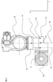
- FIG. 1 A conventional battery sensor is shown schematically.
- the battery current is measured according to the shunt principle, whereby the voltage drop at the shunt resistor caused by the current to be measured is measured according to Ohm's law and the measured voltage drop is converted into a current value using calibration parameters, which ultimately represent the resistance value of the shunt at the respective operating point .
- the core of the shunt is a measuring section, which is limited by tapping points (2) for the shunt voltage to be measured and which usually contains a special resistance alloy (1).
- the resistance alloy (1) is firmly connected to connecting parts (3) on two opposite sides viewed in the current direction, e.g. B. welded.
- the connecting parts are used to connect the Shunts to the circuit to be measured.
- connection part is therefore designed, for example, as an adapter (30) for connecting (screwing, crimping, soldering, ...) a power cable or other electrical line or can be connected to such an adapter.
- the other connection part can be connected, for example, to a pole terminal (20) for connecting to a battery pole or is itself designed as a pole terminal (20).
- the shunt, including the connecting parts thus forms part of the circuit through which the current to be measured flows.
- the two connecting parts are also each provided with at least one contact for tapping the shunt voltage across the measuring section.
- the contacts are located on the connection parts near the connecting line between the resistance alloy (1) and the respective connection part, e.g. B. at a distance of 1mm from the weld between resistance alloy (1) and the connecting part.
- An important feature of the resistance alloy (1) is a low temperature coefficient, ie the change in the resistance of the resistance alloy (1) with a change in the temperature of the resistance alloy (1) is as small as possible, at least significantly lower than the temperature coefficient of the connecting
- the resistance of the measuring section is formed as a whole from the resistance of the resistance alloy (1) and the partial resistances (Rx1, Rx2) of the connecting parts (3) within the measuring section. Since the temperature coefficient of the electrical resistance of the connecting parts (3) is significantly higher than the temperature coefficient of the resistance of the resistance alloy (1), the overall result is a temperature coefficient of the resistance of the measuring section that deviates from the temperature coefficient of the resistance material or that is greater than the temperature coefficient of the resistance material.
- a current measurement according to the invention is intended for use in battery sensors for the downstream calculation of physical variables of the battery.
- the current sensor according to the invention can also have all known further features of battery sensors, in particular one or more devices for measuring further voltages, temperatures or other variables of the battery or a motor vehicle can be integrated in the current sensor.
- the current sensor according to the invention can also be used for any other applications, for example electricity meters for measuring power consumption in power networks, power monitoring systems, etc. can be integrated into the current sensor.
- the current sensor according to the invention can also be used for any other applications, for example electricity meters for measuring power consumption in power networks, power monitoring systems, etc.
- the temperature dependence of the resistance of the measuring section has been determined, for example by measuring the temperature profile of the electrical resistance on samples. From these measured values, either a temperature coefficient of the measuring section is determined for a specific temperature range, or a characteristic curve for the electrical resistance of the measuring section at different temperatures is generated. The determination of the characteristic curve or the temperature coefficient for certain temperature ranges is usually carried out once during the development of the respective sensor type and is stored in a memory in the sensor's microcontroller.
- the temperature is measured and a correction value for the shunt resistance at the measured temperature is calculated based on the stored characteristic curve or the stored temperature coefficient.
- This correction value is taken into account when calculating the current value from the measured shunt voltage.
- current sensors according to the prior art are constructed in such a way that the current flow in the area of the measuring section (1) and the connecting parts (3) flows essentially parallel to an axis (40) of the measuring section.
- the current sensor in the Figures 2 and 3 is constructed in such a way that the current to be measured in at least one connection part (3a) does not run parallel ("parallel” should also be understood here as synonymous with “opposite parallel”) to the axis (40) of the resistance material.
- the contact points (2a, 2b) and an imaginary reference point 2c are located at approximately the same distance (in the x direction) from the respective connecting lines between resistance material (1) and connection parts (3a, 3b).
- a further axis 41 can be defined on the at least one connection part (3a), in which the current does not run parallel to the axis (40) of the resistance material, which runs through a side surface of the resistance material, which serves as a reference point for a minimum voltage drop in y -Direction can be selected.
- the imaginary reference point 2c is located on this axis 41.
- connection part (3a) The current to be measured in this connection part (3a) can thus be broken down in a two-dimensional vectorial view into a first component that runs orthogonally to the axis (40) of the resistance material and a further component that runs parallel to the axis (40).
- the resistance material and the connecting parts (3a, 3b) in the area of the resistance material should be viewed as a plane that is spanned by the two components of this two-dimensional vector current.
- the component of the current vector that runs orthogonally to the axis of the resistance material can be used as a connection vector of the two points 2c, 2b in Fig. 2 or as the y-component of the current.
- a voltage drop between points 2c and 2d can now be measured based on the y component of the current at a further imaginary point 2d, which is located on the connecting line 2c -> 2b.
- the second contact point (2b) is selected so that the temperature dependence of the quotient U/I of the voltage U measured over the measuring section (2b -> 2a) becomes minimal. (With a known calibration current I).
- FIG.3 An arrangement according to the invention can be done with the in Fig.3 equivalent circuit shown.
- the resistance material as divided into two resistors R1, R2 separated from one another along the axis 40.
- the resistors R1, R2 are made of the resistance alloy with minimum temperature coefficient of electrical resistance.
- the distances of the points 2a, 2b, 2c, 2d from the connecting surface of the resistance material with the connection parts form the resistors R3 over the distance of the material of the connection parts. These have a high temperature coefficient of electrical resistance.
- the resistors R4, R5, R6 represent the path through which the y component of the current flows. They also consist of the material of the connecting parts and have the same temperature coefficient of electrical resistance as the resistors R3.
- the temperature dependence of the resistors can be compensated for except for non-linear temperature-dependent resistance components of the resistance alloy.
- Fig. 4 shows a simulation of the temperature curve of U(2d->2a) and U(2b->2a). It can be seen that by choosing the appropriate contact points, the temperature curve can even be reversed using the compensation method.
- the influence of the temperature drift of the electrical resistances on the current measurement can be eliminated without temperature measurement and without calculation. This eliminates errors in determining the temperature of the shunt, for example.
- the temperature measurement in the battery sensor is usually carried out with a temperature sensor that is arranged on the circuit board and is therefore placed at some distance from the shunt. The temperature sensor is therefore more exposed to the heating of the electrical components on the circuit board than the shunt. Conversely, the temperature sensor is not thermally sufficiently coupled to the shunt to detect a dynamic temperature change of the shunt in real time.
- the shunt can heat up by over 100° within a few tenths of a second, although the temperature sensor only reacts after a few seconds and detects a much lower level of heating. A mathematical correction of the resistance drift would therefore occur too late and too little, which would affect the current measurement accuracy.
- the compensation mechanism is effectively a part of the drifting system and can operate in real time and fully.
- computing time and storage capacity on the microcontroller can be saved.
- the resistors R3, R4, R5 and R6 are therefore temperature dependent.
- the resistors R1 and R2, on the other hand, are largely independent of temperature or have a significantly lower temperature dependence than the resistors R3, R4, R5, R6.
- the contact point 2b is selected according to the invention so that a temperature-dependent change in the electrical resistance of the resistors R4, R5, R6 completely or partially compensates for a temperature-dependent change in the electrical resistance of the resistor R3.
- the position of point 2b in the Y direction i.e. transverse to the longitudinal direction or to the current direction of the shunt, is selected so that a temperature-dependent change in the electrical resistance of the resistors R4, R5, R6 results in a temperature-dependent change in the electrical resistance of the resistor R3 in whole or in part compensated.
Landscapes
- Engineering & Computer Science (AREA)
- Chemical & Material Sciences (AREA)
- Chemical Kinetics & Catalysis (AREA)
- Electrochemistry (AREA)
- General Chemical & Material Sciences (AREA)
- Physics & Mathematics (AREA)
- Manufacturing & Machinery (AREA)
- General Physics & Mathematics (AREA)
- Microelectronics & Electronic Packaging (AREA)
- Electromagnetism (AREA)
- Measuring Instrument Details And Bridges, And Automatic Balancing Devices (AREA)
- Secondary Cells (AREA)
Description
- Die Erfindung betrifft einen Batteriesensor, insbesondere für eine Fahrzeugbatterie, mit zwei Anschlussteilen, die über ein Widerstandselement elektrisch leitend miteinander verbunden sind, wobei an den Anschlussteilen jeweils eine Kontaktstelle vorgesehen ist.
- Batteriesensoren zur Bestimmung des Batteriezustands von Kraftfahrzeug-Batterien sind seit einiger Zeit auf dem Markt erhältlich. Gebräuchliche Batteriesensoren können in eine Anschlussklemme zum Anschließen eines Batteriekabels an einem Batteriepol integriert sein.
- Solche Batteriesensoren enthalten üblicherweise Vorrichtungen zur Messung der Batteriespannung, des von der Batterie aufgenommenen oder abgegebenen Batteriestroms und einer in einem Bauteil des Batteriesensors gemessenen Temperatur. Der Batteriesensor beinhaltet üblicherweise auch einen Mikrocontroller, der diese Messdaten zwischenspeichert, filtert und daraus weitere Batteriegrößen, beispielsweise den Ladezustand, den Innenwiderstand oder eine bestimmte Zelltemperatur berechnet. Zu den weiteren typischen Batteriesensor-Funktionen gehören die Übertragung der gemessenen oder berechneten Daten an ein angeschlossenes Steuergerät des Kraftfahrzeugs, oftmals auch eine Eigendiagnose und ein entsprechender Fehlerspeicher, ferner ein Mode-Management zur Einstellung verschiedener Betriebsarten des Batteriesensors, die seine Funktionen und seinen Stromverbrauch an die jeweiligen Erfordernisse des Kraftfahrzeug-Bordnetzes anpassen.
- Zur Messung der Rohdaten von Batteriespannung, Batteriestrom, und Temperatur stehen mehrere Analog-Digital-Wandler zur Verfügung, die zusammen mit dem Mikrocontroller und dessen Beschaltung auf einer Leiterplatte angeordnet sind, oder idealerweise in den Mikrocontroller integriert sein können. Die Strommessung erfolgt dabei gemäß des Ohmschen Gesetzes über das Shuntprinzip, das heißt, der zu messende Strom wird über einen geeigneten Widerstand, den sogenannten Shunt, in eine Spannung umgewandelt. Dafür enthält der Batteriesensor als weitere Schlüsselkomponente einen präzisen Messwiderstand (Shunt), welcher in den vom Batteriestrom durchflossenen Hauptstrompfad des Batteriesensors integriert ist. Die dem Batteriestrom proportionale Shuntspannung wird über eine entsprechende Beschaltung, die in der Regel einen Vorverstärker beinhaltet, einem Analog-Digital-Wandler zugeführt. Der Vorverstärker ist ggf. zusammen mit dem Microcontroller und/oder dem/den Analog-Digital-Wandler/n in einem integrierten Schaltkreis (ASIC) enthalten.
- Ein wichtiges Merkmal der Widerstandslegierung ist ein geringer Temperaturkoeffizient, das heißt, die Änderung des Widerstands der Widerstandslegierung mit einer Änderung der Temperatur der Widerstandslegierung ist möglichst gering, zumindest deutlich geringer als der Temperaturkoeffizient des Anschlussteils.
- Da es nun technisch nicht möglich ist, die Kontakte zum Abgreifen der Shuntspannung unmittelbar an die Schweißnähte zwischen der Widerstandslegierung und den Anschlussteilen zu platzieren, und es auch nicht vorteilhaft ist, die Kontakte auf der Widerstandslegierung zu platzieren, wird der Widerstand der Messtrecke insgesamt aus dem Widerstand der Widerstandslegierung und den Teilwiderständen der Anschlussteile innerhalb der Messstrecke gebildet. Da der Temperaturkoeffizient des elektrischen Widerstands der Anschlussteile deutlich höher als der Temperaturkoeffizient des Widerstands der Widerstandslegierung ist, ergibt sich in Summe ein Temperaturkoeffizient des Widerstands der Messstrecke, der vom Temperaturkoeffizienten des Widerstandsmaterial abweicht bzw. der größer ist als der Temperaturkoeffizient des Widerstandsmaterials.
- Zur Bestimmung des elektrischen Widerstandes und somit des Batteriestroms ist also eine genaue Temperaturbestimmung erforderlich. Zur Bestimmung der Temperatur gibt es mehrere Möglichkeiten. Am einfachsten ist eine Temperaturmessung mit einem in den integrierten Schaltkreis enthaltenen Temperatursensor, der eine der Temperatur entsprechende Spannung erzeugt, die dann einem Analog-Digital-Wandler zugeführt wird. Genau genommen wird damit aber nicht die Temperatur der Batterie oder die Umgebungstemperatur der Batterie gemessen, sondern die Temperatur am Ort des Temperatursensors. Die Temperatur am gewünschten Ort muss dann mit Hilfe eines geeigneten Temperaturmodells aus der gemessenen Temperatur berechnet werden. Die Genauigkeit der berechneten Modelltemperatur leidet unter der schwer zu bestimmenden Eigenerwärmung des integrierten Schaltkreises, der Erwärmung des Batteriesensors durch den hindurchfließenden Batteriestrom und unterschiedliche thermische Dynamik der Batterie, ihrer Umgebung und einzelner Komponenten des Batteriesensors. Eine Verbesserung wird erreicht, indem ein zweiter Temperatursensor außerhalb des integrierten Schaltkreises auf der Leiterplatte platziert wird. Somit wird wenigstens der Temperatur-Messfehler durch eine Eigenerwärmung des integrierten Schaltkreises verringert.
- In der
US 2013/0181807A1 wird das Problem dadurch gelöst, dass durch seitliche Einschnitte in den Anschlusselementen der Stromfluss bzw. die Potentiallinien derart beeinfluss werden, dass der Einschluss des Widerstandes der Anschlusselemente reduziert wird. Auch in derUS 2011/057764 werden die Kontaktpunkte der Anschlusselemente außerhalb des direkten Stromflusses angeordnet. - Aufgabe der Erfindung ist es, einen Batteriesensors bereitzustellen, der eine geringere Temperaturabhängigkeit aufweist.
- Zur Lösung der Aufgabe ist ein Batteriesensor vorgesehen, insbesondere für eine Fahrzeugbatterie, mit zwei Anschlussteilen, die über ein Widerstandselement elektrisch leitend miteinander verbunden sind, wobei das Widerstandselement plattenförmig und im Wesentlichen rechteckig ausgebildet ist, wobei die Längsachse des Widerstandselements parallel zu einer Kante des Widerstandselements verläuft, wobei an den Anschlussteilen jeweils ein Kontaktpunkt vorgesehen ist, wobei die Richtung der Längsachse zumindest eines der Anschlussteile von der Richtung der Längsachse des Widerstandselements bzw. des Shunts abweicht. Die Position der Kontaktpunkte ist quer zur Längsachse des Widerstandselements bzw. des Shunts so gewählt, dass die elektrischen Widerstände von Abschnitten der Anschlussteile die vom Strom quer zur Längsachse des Widerstandselements bzw. des Shunts durchströmt werden so dimensioniert sind, dass eine temperaturbedingte Änderung der elektrischen Widerstände eine temperaturbedingte Änderung von elektrischen Widerständen, die aus Abschnitten der Anschlussteile, die in Richtung der Längsachse des Widerstandselements bzw. des Shunts durchströmt werden, gebildet sind, ausgleichen. Die Kontaktpunkte sind quer zur Längsachse des Widerstandselements versetzt angeordnet.
- In dem Anschlussteil, dessen Richtung der Längsachse von der Längsachse des Widerstandselements abweicht, verläuft der Strom nicht parallel zur Längsrichtung des Widerstandselement. Es lässt sich eine weitere Achse definieren, die parallel zur Richtung der Längsachse des Widerstandselements und durch eine Seitenfläche des Widerstandsmaterials verläuft, die als Referenzpunkt für einen minimalen Spannungsabfall in y-Richtung gewählt werden kann. Ein gedachter Referenzpunkt befindet sich auf dieser Achse.
- Somit lässt sich der zu messende Strom in diesem Anschlussteil in zweidimensionaler vektorieller Betrachtung zerlegen in eine erste Komponente, die orthogonal zur Richtung der Längsachse des Widerstandselements verläuft, und eine weitere Komponente, die parallel zur Richtung der Längsachse des Widerstandselements verläuft.
- Dabei sollen das Widerstandselements und die Anschlussteile im Bereich des Widerstandselements als Ebene zu betrachten sein, die von den beiden Komponenten dieses zweidimensionalen vektoriellen Stroms aufgespannt wird.
- Die zur Achse des Widerstandsmaterials orthogonal verlaufende Komponente des Stromvektors kann als Verbindungsvektor zwischen dem Referenzpunk und dem bisher verwendeten Spannungsabgriffspunkt auf der Mittellinie des Widerstandselements angesehen werden bzw. als y-Komponente des Stroms.
- Erfindungsgemäß kann nun aufgrund der y-Komponente des Stroms auf einem weiteren gedachten Kontaktpunkt, der sich auf der Verbindungslinie des Referenzpunktes und des Spannungsabgriffspunktes befindet, ein Spannungsabfall zwischen den Referenzpunkt und dem Kontaktpunkt gemessen werden.
- Erfindungsgemäß wird nun, bei zuvor geeignet festgelegter Position des ersten Kontaktpunkts auf dem andere Anschlussteil, der zweite Kontaktpunkt so gewählt, dass die Temperaturabhängigkeit des Quotienten U/I der über die Messstrecke zwischen den Kontaktpunkten gemessenen Spannung minimal wird. (Bei einem bekannten Kalibrierstrom I).
- Die erfindungsgemäße Anordnung kann als Ersatzschaltbild beschrieben werden, bei dem das Widerstandsmaterial als in zwei entlang der Mittelachse voneinander getrennte Widerstände geteilt ist. Diese Widerstände bestehen aus der Widerstandslegierung mit minimalem Temperaturkoeffizienten des elektrischen Widerstands. Die Abstände der Punkte von der Verbindungsfläche des Widerstandsmaterials mit den Anschlussteilen bilden die Widerstände in Richtung der Längsachse des Widerstandselements über die Strecke des Materials der Anschlussteile. Diese weisen einen hohen Temperaturkoeffizienten des elektrischen Widerstands auf. Durch die Abstände der Kontaktstellen, des Spannungsabgriffspunkts sowie des Referenzpunkts quer zur Längsachse des Widerstandselements, die sich durch die Abstände paralleler Achsen durch die Kontaktstellen, den Spannungsabgriffspunkt sowie den definieren lassen, sind Abschnitte gebildet, die quer zur Längsachse des Widerstandselements vom Strom durchflossen sind. Sie bestehen ebenfalls aus dem Material der Anschlussteile und haben den gleichen Temperaturkoeffizienten des elektrischen Widerstands wie die Widerstände in Längsrichtung des Widerstandselements.
- Beim Einspeisen eines Stroms in die Schaltung beim Referenzpunkt wird eine Gesamtspannung zwischen dem Referenzpunkt und dem ersten Kontaktpunkt erzeugt. Gemessen wird aber nicht diese Spannung, sondern die Spannung zwischen dem ersten Kontaktpunkt und dem zweiten Kontaktpunkt. Gemäß der Spannungsteilerregel entspricht diese Spannung der zwischen dem Referenzpunkt und dem ersten Kontaktpunkt angelegt Gesamtspannung multipliziert mit dem Quotienten aus den Widerständen der beiden virtuellen Teilwiderstände.
- Durch geschickte Wahl des Teilerverhältnisses erhält man (für temperaturunabhängige Widerstände des Widerstandselements) einen temperaturabhängigen Spannungsteiler, dessen Temperaturabhängigkeit die Temperaturabhängigkeit der Gesamtspannung kompensiert.
- Im realen System lässt sich somit die Temperaturabhängigkeit der Widerstände bis auf nichtlineare temperaturabhängige Widerstandsanteile der Widerstandslegierung kompensieren.
- Bezogen auf eine Mittelachse des Widerstandselements kann sich zumindest ein Anschlussteil, dessen Richtung der Längsachse von der Richtung der Längsachse des Widerstandselements bzw. des Shunts abweicht, auf einer ersten Seite und der Kontaktpunkt dieses Anschlussteils bezogen auf eine Mittelachse auf der zweiten Seite befindet.
- Bezogen auf eine Mittelachse des Widerstandselements kann sich zumindest ein Anschlussteil, dessen Richtung der Längsachse von der Richtung der Längsachse des Widerstandselements bzw. des Shunts abweicht, auf einer ersten Seite und der Kontaktpunkt dieses Anschlussteil bezogen auf eine Richtung quer zur Längsachse des Widerstandselements weiter von diesem Anschlussteil entfernt sein als der Kontaktpunkt des anderen Anschlussteils.
- Die Kontaktpunkte weisen vorzugsweise im Wesentlichen den gleichen Abstand zum Widerstandselements.
- Die Richtung der Längsachse zumindest eines der Anschlussteile weicht vorzugsweise derart von der Richtung der Längsachse des Widerstandselements bzw. des Shunts abweicht, dass die Richtung des durch diesem Anschlussteil fließenden Stroms nicht parallel zur Längsrichtung des Widerstandselement ist.
- Vorzugsweise ist eine Spannungserfassungseinrichtung vorgesehen, die die Spannungen an den Kontaktpunkten erfasst, sowie eine Auswerteeinrichtung, die an den an den Kontaktpunkten erfassten Spannungen den über das Widerstandselement fließenden Strom ermittelt.
- Weitere Vorteile und Merkmale ergeben sich aus der nachfolgenden Beschreibung in Verbindung mit den beigefügten Zeichnungen. In diesen zeigen:
- Figur 1
- eine Schematische Darstellung eines Batteriesensors aus dem Stand der Technik;
- Figur 2
- eine Darstellung eines erfindungsgemäßen Batteriesensors;
- Figur 3
- eine Detaildarstellung des Batteriesensor aus
Figur 2 ; und - Figur 4
- eine grafische Darstellung des temperaturabhängigen Spannungsverlaufes zwischen verschiedenen Kontaktstellen des Batteriesensors.
- In
Figur 1 ist schematisch ein herkömmlicher Batteriesensor gezeigt. Die Messung des Batteriestroms erfolgt nach dem Shuntprinzip, wobei gemäß des Ohmschen Gesetzes der durch den zu messenden Strom verursachte Spannungsabfall am Shuntwiderstand gemessen wird und der gemessene Spannungsabfall anhand von Kalibrierparametern, die letztlich den Widerstandswert des Shunts am jeweiligen Arbeitspunkt repräsentieren, in einen Stromwert umgerechnet wird. Kernstück des Shunts ist eine Messstrecke, die durch Abgriffspunkte (2) für die zu messende Shuntspannung begrenzt wird, und die in der Regel eine spezielle Widerstandslegierung (1) beinhaltet. Die Widerstandslegierung (1) ist an zwei in Stromrichtung gesehen gegenüberliegenden Seiten mit Anschlussteilen (3) fest verbunden, z. B. verschweißt. Die Anschlussteile dienen dem Anschließen des Shunts an den zu messenden Stromkreis. Das eine Anschlussteil ist daher beispielsweise als Adapter (30) zum Anschließen (schrauben, crimpen, löten, ...) eines Stromkabels oder einer sonstigen elektrischen Leitung ausgebildet oder mit einem derartigen Adapter verbindbar. Das andere Anschlussteil ist beispielsweise mit einer Polklemme (20) zum Anschließen an einen Batteriepol verbindbar oder im weiteren Verlauf selbst als Polklemme (20) ausgebildet. Somit bildet der Shunt inklusive der Anschlussteile einen Teil des Stromkreises, durch den der zu messende Strom fließt. Die beiden Anschlussteile sind zudem jeweils mit mindestens einem Kontakt zum Abgreifen der Shuntspannung über der Messtrecke versehen. Idealerweise befinden sich die Kontakte jeweils auf den Anschlussteilen in der Nähe der Verbindungslinie zwischen der Widerstandslegierung (1) und dem jeweiligen anschlussteil, z. B. in einer Entfernung von 1mm von der Schweißnaht zwischen Widerstandslegierung (1) und dem Anschlussteil. Ein wichtiges Merkmal der Widerstandslegierung (1) ist ein geringer Temperaturkoeffizient, d. h. die Änderung des Widerstands der Widerstandslegierung (1) mit einer Änderung der Temperatur der Widerstandslegierung (1) ist möglichst gering, zumindest deutlich geringer als der Temperaturkoeffizient des Anschlussteils. - Da es nun technisch nicht möglich ist, die Kontakte (2) zum Abgreifen der Shuntspannung unmittelbar an die Schweißnähte zwischen der Widerstandslegierung (1) und den Anschlussteilen (3) zu platzieren, und es auch nicht vorteilhaft ist, die Kontakte auf der Widerstandslegierung (1) zu platzieren, wird der Widerstand der Messtrecke insgesamt aus dem Widerstand der Widerstandslegierung (1) und den Teilwiderständen (Rx1, Rx2) der Anschlussteile (3) innerhalb der Messstrecke gebildet. Da der Temperaturkoeffizient des elektrischen Widerstands der Anschlussteile (3) deutlich höher als der Temperaturkoeffizient des Widerstands der Widerstandslegierung (1) ist, ergibt sich in Summe ein Temperaturkoeffizient des Widerstands der Messstrecke, der vom Temperaturkoeffizienten des Widerstandsmaterial abweicht bzw. der größer ist als der Temperaturkoeffizient des Widerstandsmaterials.
- In den
Figuren 2 und3 wird nachfolgend wird ein Batteriesensor beschrieben, bei dem die Temperaturkoeffizienten der Messtrecke minimiert werden. - Eine erfindungsgemäße Strommessung wird für den Einsatz in Batteriesensoren zur nachgelagerten Berechnung von physikalischen Größen der Batterie vorgesehen. Dadurch kann der erfindungsgemäße Stromsensor auch alle bekannten weiteren Merkmale von Batteriesensoren aufweisen, insbesondere können eine oder mehrere Vorrichtungen zur Messung weiterer Spannungen, Temperaturen oder weiterer Größen der Batterie oder eines Kraftfahrzeugs in dem Stromsensor integriert sein.
- Der erfindungsgemäße Stromsensor kann aber auch für beliebige andere Anwendungen genutzt werden, zum Beispiel Stromzähler zur Messung des Stromverbrauchs in Stromnetzwerken, Stromüberwachungssystemen, etc. in dem Stromsensor integriert sein.
- Der erfindungsgemäße Stromsensor kann aber auch für beliebige andere Anwendungen genutzt werden, zum Beispiel Stromzähler zur Messung des Stromverbrauchs in Stromnetzwerken, Stromüberwachungssystemen, ... etc.
- Bisher wird die Temperaturabhängigkeit des Widerstands der Messstrecke ermittelt, beispielsweise durch Messung des Temperaturverlaufs des elektrischen Widerstands an Mustern. Aus diesen Messwerten wird entweder ein Temperaturkoeffizient der Messstrecke für einen bestimmten Temperaturbereich ermittelt, oder es wird daraus eine Kennlinie für den elektrischen Widerstand der Messstrecke bei verschiedenen Temperaturen erzeugt. Die Ermittlung der Kennlinie bzw. der Temperaturkoeffizienten für bestimmte Temperaturbereiche erfolgt in der Regel einmalig während der Entwicklung des jeweiligen Sensortyps und wird in einem Speicher im Microcontroller des Sensors hinterlegt.
- Während des Sensorbetriebs wird die Temperatur gemessen und anhand der hinterlegten Kennlinie oder des hinterlegten Temperaturkoeffizienten wird ein Korrekturwert für den Shuntwiderstand bei der gemessenen Temperatur berechnet.
- Dieser Korrekturwert wird bei der Berechnung des Stromwerts aus der gemessenen Shuntspannung mit berücksichtigt.
- Es wäre auch denkbar, die Kennlinie oder Temperaturkoeffizienten für bestimmte Temperaturbereiche im Rahmen einer Einzelteilkalibrierung für jeden einzelnen produzierten Sensor individuell zu bestimmen und im Speicher des jeweiligen Sensors zu hinterlegen. Dieser Methode steht jedoch der damit verbundene immense Aufwand entgegen.
- Weiterhin sind Stromsensoren gemäß Stand der Technik so aufgebaut, dass der Stromfluss im Bereich der Messstrecke (1) und der Anschlussteile (3) im Wesentlichen parallel zu einer Achse (40) der Messstrecke fließt.
- Der Stromsensor in den
Figuren 2 und3 ist so konstruiert, dass der zu messende Strom in mindestens einem Anschlussteil (3a) nicht parallel ("parallel" soll hier auch gleichbedeutend mit "entgegengesetzt parallel" verstanden werden) zur Achse (40) des Widerstandsmaterials verläuft. - Die Kontaktpunkte (2a, 2b) sowie ein gedachter Referenzpunkt 2c befinden sich in ungefähr gleicher Entfernung (in x-Richtung) von den jeweiligen Verbindungslinien zwischen Widerstandsmaterial (1) und Anschlussteilen (3a, 3b).
- Es lässt sich auf dem mindestens einen Anschlussteil (3a), in dem der Strom nicht parallel zur Achse (40) des Widerstandsmaterials verläuft, eine weitere Achse 41 definieren, die durch eine Seitenfläche des Widerstandsmaterials verläuft, die als Referenzpunkt für einen minimalen Spannungsabfall in y-Richtung gewählt werden kann. Der gedachte Referenzpunkt 2c befindet sich auf dieser Achse 41.
- Somit lässt sich der zu messende Strom in diesem Anschlussteil (3a) in zweidimensionaler vektorieller Betrachtung zerlegen in eine erste Komponente, die orthogonal zur Achse (40) des Widerstandsmaterials verläuft, und eine weitere Komponente, die parallel zur Achse (40) verläuft.
- Dabei sollen das Widerstandsmaterial und die Anschlussteile (3a, 3b) im Bereich des Widerstandsmaterials als Ebene zu betrachten sein, die von den beiden Komponenten dieses zweidimensionalen vektoriellen Stroms aufgespannt wird. Die zur Achse des Widerstandsmaterials orthogonal verlaufende Komponente des Stromvektors kann als Verbindungsvektor der zwei Punkte 2c, 2b in
Fig. 2 betrachtet werden bzw. als y-Komponente des Stroms. - Erfindungsgemäß kann nun aufgrund der y-Komponente des Stroms auf einem weiteren gedachten Punkt 2d, der sich auf der Verbindungslinie 2c -> 2b befindet, ein Spannungsabfall zwischen den Punkten 2c und 2d gemessen werden.
- Erfindungsgemäß wird nun, bei zuvor geeignet festgelegter Position des ersten Kontaktpunkts 2a, der zweite Kontaktpunkt (2b) so gewählt, dass die Temperaturabhängigkeit des Quotienten U/I der über die Messstrecke (2b -> 2a) gemessenen Spannung U minimal wird. (Bei einem bekannten Kalibrierstrom I).
- Eine erfindungsgemäße Anordnung kann mit dem in
Fig.3 abgebildeten Ersatzschaltbild beschrieben werden. Man stelle sich das Widerstandsmaterial als in zwei entlang der Achse 40 voneinander getrennte Widerstände R1, R2 geteilt vor. Die Widerstände R1, R2 bestehen aus der Widerstandslegierung mit minimalem Temperaturkoeffizienten des elektrischen Widerstands. Die Abstände der Punkte 2a, 2b, 2c, 2d von der Verbindungsfläche des Widerstandsmaterials mit den Anschlussteilen bilden die Widerstände R3 über die Strecke des Materials der Anschlussteile. Diese weisen einen hohen Temperaturkoeffizienten des elektrischen Widerstands auf. Die Widerstände R4, R5, R6 bilden die von der y-Komponente des Stroms durchflossene Strecke ab. Sie bestehen ebenfalls aus dem Material der Anschlussteile und haben den gleichen Temperaturkoeffizienten des elektrischen Widerstands wie die Widerstände R3. - Man erkennt, dass beim Einspeisen eines Stroms in die Schaltung beim Punkt 2c eine Spannung Utotal zwischen 2c und 2a erzeugt wird. Gemessen wird aber nicht diese Spannung, sondern es wird die Spannung zwischen 2a und 2b U(2a, 2b) gemessen. Gemäß Spannungsteilerregel gilt:

- Durch geschickte Wahl des Teilerverhältnisses erhält man (für temperaturunabhängige R1, R2) einen temperaturabhängigen Spannungsteiler, dessen Temperaturabhängigkeit die Temperaturabhängigkeit der Gesamtspannung Utotal kompensiert.
- Im realen System lässt sich somit die Temperaturabhängigkeit der Widerstände bis auf nichtlineare Temperaturabhängige Widerstandsanteile der Widerstandslegierung kompensieren.
-
Fig. 4 zeigt eine Simulation des Temperaturverlaufs von U(2d->2a) und von U(2b->2a). Man erkennt, dass sich durch geeignete Wahl der Kontaktpunkte der Temperaturverlauf mit der Kompensationsmethode sogar umkehren lässt. - Der Einfluss der Temperaturdrift der elektrischen Widerstände auf die Strommessung kann ohne Temperaturmessung und ohne Berechnung eliminiert werden. Damit werden beispielsweise Fehler der Temperaturbestimmung des Shunts eliminiert. Wie eingangs erwähnt, erfolgt die Temperaturmessung im Batteriesensor in der Regel mit einem Temperatursensor, der auf der Leiterplatte angeordnet ist und somit in einiger Entfernung vom Shunt platziert ist. Somit ist der Temperatursensor der Erwärmung der elektrischen Bauteile auf der Leiterplatte stärker ausgesetzt als der Shunt. Umgekehrt ist der Temperatursensor thermisch nicht ausreichend an den Shunt gekoppelt, um eine dynamische Temperaturänderung des Shunts in Echtzeit zu erkennen. Beispielsweise kann sich der Shunt bei hohen Strömen innerhalb weniger Zehntelsekunden um über 100° erwärmen, wobei der Temperatursensor erst nach einigen Sekunden reagiert und eine weit geringere Erwärmung erkennt. Somit würde eine rechnerische Korrektur der Widerstandsdrift zu spät und zu gering erfolgen, womit die Strom-Messgenauigkeit beeinträchtigt wird.
- Mit der vorliegenden Erfindung ist der Kompensationsmechanismus praktisch ein Teil des driftenden Systems und kann in Echtzeit und vollständig wirken. Zudem kann Rechenzeit und Speicherkapazität auf dem Microcontroller gespart werden.
- Die Widerstände R3, R4, R5 und R6 sind also temperaturabhängig. Die Widerstände R1 und R2 sind dagegen weitgehend temperaturunabhängig bzw. weisen eine wesentlich geringere Temperaturabhängigkeit auf als die Widerstände R3, R4, R5, R6.
- Der Kontaktpunkt 2b wird gemäß der Erfindung so gewählt, dass eine temperaturabhängige Änderung des elektrischen Widerstandes der Widerstände R4, R5, R6 eine temperaturbedingte Änderung des elektrischen Widerstandes des Widerstandes R3 ganz oder teilweise kompensiert.
- Hierzu wird insbesondere die Position des Punktes 2b in Y Richtung also quer zur Längsrichtung bzw. zur Stromrichtung des Shunts so gewählt, dass eine temperaturabhängige Änderung des elektrischen Widerstandes der Widerstände R4, R5, R6 eine temperaturbedingte Änderung des elektrischen Widerstandes des Widerstandes R3 ganz oder teilweise kompensiert.
Claims (6)
- Batteriesensor, insbesondere für eine Fahrzeugbatterie, mit zwei Anschlussteilen (3a, 3b), die über ein Widerstandselement (1) elektrisch leitend miteinander verbunden sind, wobei das Widerstandselement plattenförmig und im Wesentlichen rechteckig ausgebildet ist, wobei die Längsachse des Widerstandselements parallel zu einer Kante des Widerstandselements verläuft, wobei an den Anschlussteilen (3a, 3b) jeweils einen Kontaktpunkt (2a, 2b) vorgesehen ist, wobei die Richtung der Längsachse zumindest eines der Anschlussteile (3a, 3b) von der Richtung der Längsachse des Widerstandselements (1) abweicht, dadurch gekennzeichnet, dass die Position der Kontaktpunkte (2a, 2b) quer zur Längsachse des Widerstandselements so gewählt ist, dass die elektrischen Widerstände (R4, R5, R6) von Abschnitten der Anschlussteile (3a, 3b) die vom Strom quer zur Längsachse (y-Richtung) des Widerstandselements durchströmt werden so dimensioniert sind, dass eine temperaturbedingte Änderung der elektrischen Widerstände (R4, R5, R6) eine temperaturbedingte Änderung von elektrischen Widerständen (R3), die aus Abschnitten der Anschlussteile (3a, 3b), die in Richtung der Längsachse des Widerstandselements durchströmt werden, gebildet sind, ausgleichen, dass die Kontaktpunkte (2a, 2b) quer zur Längsachse des Widerstandselements versetzt angeordnet sind.
- Batteriesensor nach einem der Ansprüche 1 und 2, dadurch gekennzeichnet, dass sich bezogen auf eine Mittelachse des Widerstandselements zumindest ein Anschlussteil, dessen Richtung der Längsachse von der Richtung der Längsachse des Widerstandselements (1) abweicht, auf einer ersten Seite und der Kontaktpunkt (2b) dieses Anschlussteils bezogen auf eine Mittelachse auf der zweiten Seite befindet.
- Batteriesensor nach einem der vorhergehenden Ansprüche, dadurch gekennzeichnet, dass sich bezogen auf eine Mittelachse des Widerstandselements zumindest ein Anschlussteil, dessen Richtung der Längsachse von der Richtung der Längsachse des Widerstandselements (1) abweicht, auf einer ersten Seite und der Kontaktpunkt dieses Anschlussteil bezogen auf eine Richtung quer zur Längsachse des Widerstandselements weiter von diesem Anschlussteil entfernt ist als der Kontaktpunkt des anderen Anschlussteils.
- Batteriesensor nach einem der vorhergehenden Ansprüche, dadurch gekennzeichnet, dass die Kontaktpunkte im Wesentlichen den gleichen Abstand zum Widerstandselements aufweisen.
- Batteriesensor nach einem der vorhergehenden Ansprüche, dadurch gekennzeichnet, dass die Richtung der Längsachse zumindest eines der Anschlussteile (3a, 3b) derart von der Richtung der Längsachse des Widerstandselements (1) abweicht, dass die Richtung des durch diesem Anschlussteil fließenden Stroms nicht parallel zur Längsrichtung des Widerstandselement ist.
- Batteriesensor nach einem der vorhergehenden Ansprüche, dadurch gekennzeichnet, dass eine Spannungserfassungseinrichtung vorgesehen ist, die die Spannungen an den Kontaktpunkten (2a, 2b) erfasst, sowie eine Auswerteeinrichtung, die an den an den Kontaktpunkten erfassten Spannungen den über das Widerstandselement fließenden Strom ermittelt.
Applications Claiming Priority (2)
| Application Number | Priority Date | Filing Date | Title |
|---|---|---|---|
| DE102018216184 | 2018-09-21 | ||
| PCT/EP2019/075355 WO2020058487A1 (de) | 2018-09-21 | 2019-09-20 | Batteriesensor zur temperaturunabhängigen strommessung mit einem shunt |
Publications (2)
| Publication Number | Publication Date |
|---|---|
| EP3853620A1 EP3853620A1 (de) | 2021-07-28 |
| EP3853620B1 true EP3853620B1 (de) | 2023-11-08 |
Family
ID=68109281
Family Applications (1)
| Application Number | Title | Priority Date | Filing Date |
|---|---|---|---|
| EP19780175.6A Active EP3853620B1 (de) | 2018-09-21 | 2019-09-20 | Batteriesensor zur temperaturunabhängigen strommessung mit einem shunt |
Country Status (4)
| Country | Link |
|---|---|
| EP (1) | EP3853620B1 (de) |
| CN (1) | CN112714873B (de) |
| DE (1) | DE102019214378A1 (de) |
| WO (1) | WO2020058487A1 (de) |
Families Citing this family (1)
| Publication number | Priority date | Publication date | Assignee | Title |
|---|---|---|---|---|
| CN112362946A (zh) * | 2020-11-27 | 2021-02-12 | 湖南新海讯光电有限公司 | 一种基于分流器的电流测量方法及装置 |
Family Cites Families (8)
| Publication number | Priority date | Publication date | Assignee | Title |
|---|---|---|---|---|
| DE10000500B4 (de) * | 2000-01-08 | 2004-09-02 | Robert Bosch Gmbh | Vorrichtung zur Messung eines in einem Elektronikmodul fließenden Stroms |
| DE10336107B3 (de) * | 2003-08-06 | 2005-04-28 | Siemens Ag | Messwiderstand für eine Batteriesensorikeinheit und Batteriesensorikeinheit |
| DE102004055848B4 (de) * | 2004-11-19 | 2008-02-21 | Bayerische Motoren Werke Ag | Batteriesensorvorrichtung |
| EP2165205B1 (de) * | 2007-07-13 | 2013-06-26 | Auto-Kabel Managementgesellschaft mbH | Beschichtetes kraftfahrzeugbatteriesensorelement sowie verfahren zur herstellung eines kraftfahrzeugbatteriesensorelementes |
| KR20170061185A (ko) * | 2009-09-04 | 2017-06-02 | 비쉐이 데일 일렉트로닉스, 엘엘씨 | 저항 온도 계수 보상을 갖춘 저항기 |
| US20110089931A1 (en) * | 2009-10-19 | 2011-04-21 | Nemic-Lambda Ltd. | Temperature-compensated shunt current measurement |
| DE102010035485A1 (de) * | 2010-08-26 | 2012-03-01 | Isabellenhütte Heusler Gmbh & Co. Kg | Strommesswiderstand |
| DE102013210128A1 (de) * | 2013-03-05 | 2014-09-11 | Continental Automotive Gmbh | Einstückig ausgebildete Stromsensorvorrichtung |
-
2019
- 2019-09-20 DE DE102019214378.4A patent/DE102019214378A1/de active Pending
- 2019-09-20 EP EP19780175.6A patent/EP3853620B1/de active Active
- 2019-09-20 CN CN201980061075.1A patent/CN112714873B/zh active Active
- 2019-09-20 WO PCT/EP2019/075355 patent/WO2020058487A1/de not_active Ceased
Also Published As
| Publication number | Publication date |
|---|---|
| CN112714873B (zh) | 2024-08-02 |
| CN112714873A (zh) | 2021-04-27 |
| DE102019214378A1 (de) | 2020-03-26 |
| WO2020058487A1 (de) | 2020-03-26 |
| EP3853620A1 (de) | 2021-07-28 |
Similar Documents
| Publication | Publication Date | Title |
|---|---|---|
| DE102006040768B4 (de) | Temperatursensorsteuerungvorrichtung | |
| DE202021105281U1 (de) | Strommesswiderstand | |
| DE102004062655B4 (de) | Verfahren zum Korrigieren einer durch eine elektrische Spannungsmessung indirekt durchgeführten elektrischen Strommessung | |
| DE102017221612A1 (de) | Stromsensor und Verfahren zum Messen eines elektrischen Stroms | |
| DE102016204941A1 (de) | Verfahren zum Bestimmen eines Laststroms und Batteriesensor | |
| EP3853620B1 (de) | Batteriesensor zur temperaturunabhängigen strommessung mit einem shunt | |
| DE19800628C2 (de) | Luftdurchsatz-Meßelement und Luftdurchsatz-Meßvorrichtung | |
| EP3247984B1 (de) | Vorrichtung und verfahren zur temperaturerfassung sowie verwendung der vorrichtung | |
| DE112023000777T5 (de) | Shunt-widerstand und stromerfassungsvorrichtung | |
| EP0667509B1 (de) | Temperaturkompensation bei Massenstromsensoren nach dem Prinzip des Hitzdraht-Anemometers | |
| EP2546664B1 (de) | Verfahren zur Überprüfung einer Messanordnung zur Spannungsbestimmung und Verfahren zum Laden einer ladbaren Spannungsquelle | |
| WO2009112412A1 (de) | Anordnung zum messen einer stromstärke, schaltanordnung sowie verfahren zum messen einer stromstärke | |
| EP3058379A1 (de) | Verfahren zum messen einer temperatur | |
| DE2852904A1 (de) | Durchflussmesseinrichtung | |
| EP3640656B1 (de) | Verfahren zum betrieb eines batteriesensors und batteriesensor | |
| EP1561101A1 (de) | Verfahren und vorrichtung zur überwachung einer referenzhalbzelle | |
| DE102021130852B3 (de) | Identifikation der Benetzung von NTC-Temperaturmesswiderständen in sicherheitsrelevanten Vorrichtungen | |
| EP4278194B1 (de) | Strommesswiderstand | |
| EP4012428B1 (de) | Widerstandselement und verfahren zur herstellung eines widerstandselements | |
| AT527390B1 (de) | Shunt mit referenzleiter | |
| EP0675344B1 (de) | Füllstandssensor | |
| DE102024109634B3 (de) | Strommessanordnung, Abgleichanlage, Abgleichverfahren und Herstellungsverfahren für eine Strommessanordnung | |
| DE1573387C (de) | Temperatur Meßgerat | |
| EP3995837B1 (de) | Widerstandsbaugruppe und batteriesensor mit widerstandsbaugruppe | |
| DE102019217376A1 (de) | Verfahren zur Prüfung eines Batteriesensors und Batteriesensor |
Legal Events
| Date | Code | Title | Description |
|---|---|---|---|
| STAA | Information on the status of an ep patent application or granted ep patent |
Free format text: STATUS: UNKNOWN |
|
| STAA | Information on the status of an ep patent application or granted ep patent |
Free format text: STATUS: THE INTERNATIONAL PUBLICATION HAS BEEN MADE |
|
| PUAI | Public reference made under article 153(3) epc to a published international application that has entered the european phase |
Free format text: ORIGINAL CODE: 0009012 |
|
| STAA | Information on the status of an ep patent application or granted ep patent |
Free format text: STATUS: REQUEST FOR EXAMINATION WAS MADE |
|
| 17P | Request for examination filed |
Effective date: 20210421 |
|
| AK | Designated contracting states |
Kind code of ref document: A1 Designated state(s): AL AT BE BG CH CY CZ DE DK EE ES FI FR GB GR HR HU IE IS IT LI LT LU LV MC MK MT NL NO PL PT RO RS SE SI SK SM TR |
|
| DAV | Request for validation of the european patent (deleted) | ||
| DAX | Request for extension of the european patent (deleted) | ||
| RAP1 | Party data changed (applicant data changed or rights of an application transferred) |
Owner name: CONTINENTAL AUTOMOTIVE TECHNOLOGIES GMBH |
|
| GRAP | Despatch of communication of intention to grant a patent |
Free format text: ORIGINAL CODE: EPIDOSNIGR1 |
|
| STAA | Information on the status of an ep patent application or granted ep patent |
Free format text: STATUS: GRANT OF PATENT IS INTENDED |
|
| INTG | Intention to grant announced |
Effective date: 20230511 |
|
| GRAS | Grant fee paid |
Free format text: ORIGINAL CODE: EPIDOSNIGR3 |
|
| GRAA | (expected) grant |
Free format text: ORIGINAL CODE: 0009210 |
|
| STAA | Information on the status of an ep patent application or granted ep patent |
Free format text: STATUS: THE PATENT HAS BEEN GRANTED |
|
| AK | Designated contracting states |
Kind code of ref document: B1 Designated state(s): AL AT BE BG CH CY CZ DE DK EE ES FI FR GB GR HR HU IE IS IT LI LT LU LV MC MK MT NL NO PL PT RO RS SE SI SK SM TR |
|
| REG | Reference to a national code |
Ref country code: GB Ref legal event code: FG4D Free format text: NOT ENGLISH |
|
| REG | Reference to a national code |
Ref country code: CH Ref legal event code: EP |
|
| REG | Reference to a national code |
Ref country code: DE Ref legal event code: R096 Ref document number: 502019009888 Country of ref document: DE |
|
| REG | Reference to a national code |
Ref country code: IE Ref legal event code: FG4D Free format text: LANGUAGE OF EP DOCUMENT: GERMAN |
|
| REG | Reference to a national code |
Ref country code: DE Ref legal event code: R081 Ref document number: 502019009888 Country of ref document: DE Owner name: CONTINENTAL AUTOMOTIVE TECHNOLOGIES GMBH, DE Free format text: FORMER OWNER: CONTINENTAL AUTOMOTIVE TECHNOLOGIES GMBH, 30165 HANNOVER, DE Ref country code: DE Ref legal event code: R081 Ref document number: 502019009888 Country of ref document: DE Owner name: AUMOVIO GERMANY GMBH, DE Free format text: FORMER OWNER: CONTINENTAL AUTOMOTIVE TECHNOLOGIES GMBH, 30165 HANNOVER, DE |
|
| REG | Reference to a national code |
Ref country code: LT Ref legal event code: MG9D |
|
| REG | Reference to a national code |
Ref country code: NL Ref legal event code: MP Effective date: 20231108 |
|
| PG25 | Lapsed in a contracting state [announced via postgrant information from national office to epo] |
Ref country code: GR Free format text: LAPSE BECAUSE OF FAILURE TO SUBMIT A TRANSLATION OF THE DESCRIPTION OR TO PAY THE FEE WITHIN THE PRESCRIBED TIME-LIMIT Effective date: 20240209 |
|
| PG25 | Lapsed in a contracting state [announced via postgrant information from national office to epo] |
Ref country code: IS Free format text: LAPSE BECAUSE OF FAILURE TO SUBMIT A TRANSLATION OF THE DESCRIPTION OR TO PAY THE FEE WITHIN THE PRESCRIBED TIME-LIMIT Effective date: 20240308 |
|
| PG25 | Lapsed in a contracting state [announced via postgrant information from national office to epo] |
Ref country code: LT Free format text: LAPSE BECAUSE OF FAILURE TO SUBMIT A TRANSLATION OF THE DESCRIPTION OR TO PAY THE FEE WITHIN THE PRESCRIBED TIME-LIMIT Effective date: 20231108 |
|
| PG25 | Lapsed in a contracting state [announced via postgrant information from national office to epo] |
Ref country code: NL Free format text: LAPSE BECAUSE OF FAILURE TO SUBMIT A TRANSLATION OF THE DESCRIPTION OR TO PAY THE FEE WITHIN THE PRESCRIBED TIME-LIMIT Effective date: 20231108 |
|
| RAP4 | Party data changed (patent owner data changed or rights of a patent transferred) |
Owner name: CONTINENTAL AUTOMOTIVE TECHNOLOGIES GMBH |
|
| PG25 | Lapsed in a contracting state [announced via postgrant information from national office to epo] |
Ref country code: ES Free format text: LAPSE BECAUSE OF FAILURE TO SUBMIT A TRANSLATION OF THE DESCRIPTION OR TO PAY THE FEE WITHIN THE PRESCRIBED TIME-LIMIT Effective date: 20231108 |
|
| PG25 | Lapsed in a contracting state [announced via postgrant information from national office to epo] |
Ref country code: NL Free format text: LAPSE BECAUSE OF FAILURE TO SUBMIT A TRANSLATION OF THE DESCRIPTION OR TO PAY THE FEE WITHIN THE PRESCRIBED TIME-LIMIT Effective date: 20231108 Ref country code: LT Free format text: LAPSE BECAUSE OF FAILURE TO SUBMIT A TRANSLATION OF THE DESCRIPTION OR TO PAY THE FEE WITHIN THE PRESCRIBED TIME-LIMIT Effective date: 20231108 Ref country code: IS Free format text: LAPSE BECAUSE OF FAILURE TO SUBMIT A TRANSLATION OF THE DESCRIPTION OR TO PAY THE FEE WITHIN THE PRESCRIBED TIME-LIMIT Effective date: 20240308 Ref country code: GR Free format text: LAPSE BECAUSE OF FAILURE TO SUBMIT A TRANSLATION OF THE DESCRIPTION OR TO PAY THE FEE WITHIN THE PRESCRIBED TIME-LIMIT Effective date: 20240209 Ref country code: ES Free format text: LAPSE BECAUSE OF FAILURE TO SUBMIT A TRANSLATION OF THE DESCRIPTION OR TO PAY THE FEE WITHIN THE PRESCRIBED TIME-LIMIT Effective date: 20231108 Ref country code: BG Free format text: LAPSE BECAUSE OF FAILURE TO SUBMIT A TRANSLATION OF THE DESCRIPTION OR TO PAY THE FEE WITHIN THE PRESCRIBED TIME-LIMIT Effective date: 20240208 Ref country code: PT Free format text: LAPSE BECAUSE OF FAILURE TO SUBMIT A TRANSLATION OF THE DESCRIPTION OR TO PAY THE FEE WITHIN THE PRESCRIBED TIME-LIMIT Effective date: 20240308 |
|
| REG | Reference to a national code |
Ref country code: CH Ref legal event code: PK Free format text: DIE PUBLIKATION VOM 27.03.2024 WURDE AM 24.04.2024 IRRTUEMLICHERWEISE ERNEUT PUBLIZIERT. LA PUBLICATION DU 27.03.2024 A ETE REPUBLIEE PAR ERREUR LE 24.04.2024. LA PUBBLICAZIONE DEL 27.03.2024 E STATA ERRONEAMENTE RIPUBBLICATA IL 24.04.2024. |
|
| PG25 | Lapsed in a contracting state [announced via postgrant information from national office to epo] |
Ref country code: SE Free format text: LAPSE BECAUSE OF FAILURE TO SUBMIT A TRANSLATION OF THE DESCRIPTION OR TO PAY THE FEE WITHIN THE PRESCRIBED TIME-LIMIT Effective date: 20231108 Ref country code: RS Free format text: LAPSE BECAUSE OF FAILURE TO SUBMIT A TRANSLATION OF THE DESCRIPTION OR TO PAY THE FEE WITHIN THE PRESCRIBED TIME-LIMIT Effective date: 20231108 Ref country code: PL Free format text: LAPSE BECAUSE OF FAILURE TO SUBMIT A TRANSLATION OF THE DESCRIPTION OR TO PAY THE FEE WITHIN THE PRESCRIBED TIME-LIMIT Effective date: 20231108 Ref country code: NO Free format text: LAPSE BECAUSE OF FAILURE TO SUBMIT A TRANSLATION OF THE DESCRIPTION OR TO PAY THE FEE WITHIN THE PRESCRIBED TIME-LIMIT Effective date: 20240208 Ref country code: LV Free format text: LAPSE BECAUSE OF FAILURE TO SUBMIT A TRANSLATION OF THE DESCRIPTION OR TO PAY THE FEE WITHIN THE PRESCRIBED TIME-LIMIT Effective date: 20231108 Ref country code: HR Free format text: LAPSE BECAUSE OF FAILURE TO SUBMIT A TRANSLATION OF THE DESCRIPTION OR TO PAY THE FEE WITHIN THE PRESCRIBED TIME-LIMIT Effective date: 20231108 |
|
| PG25 | Lapsed in a contracting state [announced via postgrant information from national office to epo] |
Ref country code: DK Free format text: LAPSE BECAUSE OF FAILURE TO SUBMIT A TRANSLATION OF THE DESCRIPTION OR TO PAY THE FEE WITHIN THE PRESCRIBED TIME-LIMIT Effective date: 20231108 |
|
| PG25 | Lapsed in a contracting state [announced via postgrant information from national office to epo] |
Ref country code: CZ Free format text: LAPSE BECAUSE OF FAILURE TO SUBMIT A TRANSLATION OF THE DESCRIPTION OR TO PAY THE FEE WITHIN THE PRESCRIBED TIME-LIMIT Effective date: 20231108 |
|
| PG25 | Lapsed in a contracting state [announced via postgrant information from national office to epo] |
Ref country code: SK Free format text: LAPSE BECAUSE OF FAILURE TO SUBMIT A TRANSLATION OF THE DESCRIPTION OR TO PAY THE FEE WITHIN THE PRESCRIBED TIME-LIMIT Effective date: 20231108 |
|
| PG25 | Lapsed in a contracting state [announced via postgrant information from national office to epo] |
Ref country code: SM Free format text: LAPSE BECAUSE OF FAILURE TO SUBMIT A TRANSLATION OF THE DESCRIPTION OR TO PAY THE FEE WITHIN THE PRESCRIBED TIME-LIMIT Effective date: 20231108 Ref country code: SK Free format text: LAPSE BECAUSE OF FAILURE TO SUBMIT A TRANSLATION OF THE DESCRIPTION OR TO PAY THE FEE WITHIN THE PRESCRIBED TIME-LIMIT Effective date: 20231108 Ref country code: RO Free format text: LAPSE BECAUSE OF FAILURE TO SUBMIT A TRANSLATION OF THE DESCRIPTION OR TO PAY THE FEE WITHIN THE PRESCRIBED TIME-LIMIT Effective date: 20231108 Ref country code: EE Free format text: LAPSE BECAUSE OF FAILURE TO SUBMIT A TRANSLATION OF THE DESCRIPTION OR TO PAY THE FEE WITHIN THE PRESCRIBED TIME-LIMIT Effective date: 20231108 Ref country code: DK Free format text: LAPSE BECAUSE OF FAILURE TO SUBMIT A TRANSLATION OF THE DESCRIPTION OR TO PAY THE FEE WITHIN THE PRESCRIBED TIME-LIMIT Effective date: 20231108 Ref country code: CZ Free format text: LAPSE BECAUSE OF FAILURE TO SUBMIT A TRANSLATION OF THE DESCRIPTION OR TO PAY THE FEE WITHIN THE PRESCRIBED TIME-LIMIT Effective date: 20231108 |
|
| REG | Reference to a national code |
Ref country code: DE Ref legal event code: R097 Ref document number: 502019009888 Country of ref document: DE |
|
| PLBE | No opposition filed within time limit |
Free format text: ORIGINAL CODE: 0009261 |
|
| STAA | Information on the status of an ep patent application or granted ep patent |
Free format text: STATUS: NO OPPOSITION FILED WITHIN TIME LIMIT |
|
| 26N | No opposition filed |
Effective date: 20240809 |
|
| PG25 | Lapsed in a contracting state [announced via postgrant information from national office to epo] |
Ref country code: SI Free format text: LAPSE BECAUSE OF FAILURE TO SUBMIT A TRANSLATION OF THE DESCRIPTION OR TO PAY THE FEE WITHIN THE PRESCRIBED TIME-LIMIT Effective date: 20231108 |
|
| PG25 | Lapsed in a contracting state [announced via postgrant information from national office to epo] |
Ref country code: SI Free format text: LAPSE BECAUSE OF FAILURE TO SUBMIT A TRANSLATION OF THE DESCRIPTION OR TO PAY THE FEE WITHIN THE PRESCRIBED TIME-LIMIT Effective date: 20231108 |
|
| PG25 | Lapsed in a contracting state [announced via postgrant information from national office to epo] |
Ref country code: MC Free format text: LAPSE BECAUSE OF FAILURE TO SUBMIT A TRANSLATION OF THE DESCRIPTION OR TO PAY THE FEE WITHIN THE PRESCRIBED TIME-LIMIT Effective date: 20231108 |
|
| REG | Reference to a national code |
Ref country code: CH Ref legal event code: PL |
|
| PG25 | Lapsed in a contracting state [announced via postgrant information from national office to epo] |
Ref country code: LU Free format text: LAPSE BECAUSE OF NON-PAYMENT OF DUE FEES Effective date: 20240920 |
|
| GBPC | Gb: european patent ceased through non-payment of renewal fee |
Effective date: 20240920 |
|
| PG25 | Lapsed in a contracting state [announced via postgrant information from national office to epo] |
Ref country code: GB Free format text: LAPSE BECAUSE OF NON-PAYMENT OF DUE FEES Effective date: 20240920 |
|
| REG | Reference to a national code |
Ref country code: BE Ref legal event code: MM Effective date: 20240930 |
|
| PG25 | Lapsed in a contracting state [announced via postgrant information from national office to epo] |
Ref country code: BE Free format text: LAPSE BECAUSE OF NON-PAYMENT OF DUE FEES Effective date: 20240930 |
|
| PG25 | Lapsed in a contracting state [announced via postgrant information from national office to epo] |
Ref country code: CH Free format text: LAPSE BECAUSE OF NON-PAYMENT OF DUE FEES Effective date: 20240930 |
|
| PG25 | Lapsed in a contracting state [announced via postgrant information from national office to epo] |
Ref country code: IE Free format text: LAPSE BECAUSE OF NON-PAYMENT OF DUE FEES Effective date: 20240920 |
|
| PG25 | Lapsed in a contracting state [announced via postgrant information from national office to epo] |
Ref country code: FI Free format text: LAPSE BECAUSE OF FAILURE TO SUBMIT A TRANSLATION OF THE DESCRIPTION OR TO PAY THE FEE WITHIN THE PRESCRIBED TIME-LIMIT Effective date: 20231108 |
|
| PGFP | Annual fee paid to national office [announced via postgrant information from national office to epo] |
Ref country code: DE Payment date: 20250930 Year of fee payment: 7 |
|
| PGFP | Annual fee paid to national office [announced via postgrant information from national office to epo] |
Ref country code: IT Payment date: 20250923 Year of fee payment: 7 |
|
| PGFP | Annual fee paid to national office [announced via postgrant information from national office to epo] |
Ref country code: FR Payment date: 20250922 Year of fee payment: 7 |
|
| REG | Reference to a national code |
Ref country code: AT Ref legal event code: MM01 Ref document number: 1630053 Country of ref document: AT Kind code of ref document: T Effective date: 20240920 |
|
| PG25 | Lapsed in a contracting state [announced via postgrant information from national office to epo] |
Ref country code: AT Free format text: LAPSE BECAUSE OF NON-PAYMENT OF DUE FEES Effective date: 20240920 |
|
| REG | Reference to a national code |
Ref country code: DE Ref legal event code: R081 Ref document number: 502019009888 Country of ref document: DE Owner name: AUMOVIO GERMANY GMBH, DE Free format text: FORMER OWNER: CONTINENTAL AUTOMOTIVE TECHNOLOGIES GMBH, 30175 HANNOVER, DE |
|
| PG25 | Lapsed in a contracting state [announced via postgrant information from national office to epo] |
Ref country code: CY Free format text: LAPSE BECAUSE OF FAILURE TO SUBMIT A TRANSLATION OF THE DESCRIPTION OR TO PAY THE FEE WITHIN THE PRESCRIBED TIME-LIMIT; INVALID AB INITIO Effective date: 20190920 |
|
| PG25 | Lapsed in a contracting state [announced via postgrant information from national office to epo] |
Ref country code: HU Free format text: LAPSE BECAUSE OF FAILURE TO SUBMIT A TRANSLATION OF THE DESCRIPTION OR TO PAY THE FEE WITHIN THE PRESCRIBED TIME-LIMIT; INVALID AB INITIO Effective date: 20190920 |