EP3853508B1 - Verfahren und system zur verlegung einer rohrleitung auf dem boden eines gewässers - Google Patents
Verfahren und system zur verlegung einer rohrleitung auf dem boden eines gewässers Download PDFInfo
- Publication number
- EP3853508B1 EP3853508B1 EP19787078.5A EP19787078A EP3853508B1 EP 3853508 B1 EP3853508 B1 EP 3853508B1 EP 19787078 A EP19787078 A EP 19787078A EP 3853508 B1 EP3853508 B1 EP 3853508B1
- Authority
- EP
- European Patent Office
- Prior art keywords
- pipeline
- zone
- laying
- curved section
- water
- Prior art date
- Legal status (The legal status is an assumption and is not a legal conclusion. Google has not performed a legal analysis and makes no representation as to the accuracy of the status listed.)
- Active
Links
Images




Classifications
-
- F—MECHANICAL ENGINEERING; LIGHTING; HEATING; WEAPONS; BLASTING
- F16—ENGINEERING ELEMENTS AND UNITS; GENERAL MEASURES FOR PRODUCING AND MAINTAINING EFFECTIVE FUNCTIONING OF MACHINES OR INSTALLATIONS; THERMAL INSULATION IN GENERAL
- F16L—PIPES; JOINTS OR FITTINGS FOR PIPES; SUPPORTS FOR PIPES, CABLES OR PROTECTIVE TUBING; MEANS FOR THERMAL INSULATION IN GENERAL
- F16L1/00—Laying or reclaiming pipes; Repairing or joining pipes on or under water
- F16L1/12—Laying or reclaiming pipes on or under water
- F16L1/16—Laying or reclaiming pipes on or under water on the bottom
-
- F—MECHANICAL ENGINEERING; LIGHTING; HEATING; WEAPONS; BLASTING
- F16—ENGINEERING ELEMENTS AND UNITS; GENERAL MEASURES FOR PRODUCING AND MAINTAINING EFFECTIVE FUNCTIONING OF MACHINES OR INSTALLATIONS; THERMAL INSULATION IN GENERAL
- F16L—PIPES; JOINTS OR FITTINGS FOR PIPES; SUPPORTS FOR PIPES, CABLES OR PROTECTIVE TUBING; MEANS FOR THERMAL INSULATION IN GENERAL
- F16L1/00—Laying or reclaiming pipes; Repairing or joining pipes on or under water
- F16L1/12—Laying or reclaiming pipes on or under water
- F16L1/20—Accessories therefor, e.g. floats or weights
-
- F—MECHANICAL ENGINEERING; LIGHTING; HEATING; WEAPONS; BLASTING
- F16—ENGINEERING ELEMENTS AND UNITS; GENERAL MEASURES FOR PRODUCING AND MAINTAINING EFFECTIVE FUNCTIONING OF MACHINES OR INSTALLATIONS; THERMAL INSULATION IN GENERAL
- F16L—PIPES; JOINTS OR FITTINGS FOR PIPES; SUPPORTS FOR PIPES, CABLES OR PROTECTIVE TUBING; MEANS FOR THERMAL INSULATION IN GENERAL
- F16L1/00—Laying or reclaiming pipes; Repairing or joining pipes on or under water
- F16L1/12—Laying or reclaiming pipes on or under water
- F16L1/20—Accessories therefor, e.g. floats or weights
- F16L1/235—Apparatus for controlling the pipe during laying
-
- F—MECHANICAL ENGINEERING; LIGHTING; HEATING; WEAPONS; BLASTING
- F16—ENGINEERING ELEMENTS AND UNITS; GENERAL MEASURES FOR PRODUCING AND MAINTAINING EFFECTIVE FUNCTIONING OF MACHINES OR INSTALLATIONS; THERMAL INSULATION IN GENERAL
- F16L—PIPES; JOINTS OR FITTINGS FOR PIPES; SUPPORTS FOR PIPES, CABLES OR PROTECTIVE TUBING; MEANS FOR THERMAL INSULATION IN GENERAL
- F16L1/00—Laying or reclaiming pipes; Repairing or joining pipes on or under water
- F16L1/12—Laying or reclaiming pipes on or under water
- F16L1/123—Devices for the protection of pipes under water
Definitions
- the present invention relates to a method and a system for laying a pipeline on the bed of a body of water.
- Hydrocarbon transport pipelines are laid on the bed of a body of water by laying vessels, each of which is configured to assemble the pipeline on board the laying vessel and launch the pipeline as it is assembled.
- the laying vessel therefore includes assembly equipment and a launch ramp for the so-called S-laying, or a launch tower for the so-called J-laying.
- S and J identify the type of laying in relation to the shape taken by the pipeline between the laying vessel and the bed of the body of water.
- the so-called S-laying is particularly suitable for laying pipelines with high productivity in medium shallow water
- the so-called J-laying is suitable for laying the pipeline in deep water.
- the pipeline is flexible enough to adapt to the profile of the bed of the body of water.
- the profile of the bed of the body of water has abrupt changes in slope and the diameter of the pipeline is relatively large, resulting in a reduced flexibility of the pipeline.
- the combination of the above factors brings about configurations in which the pipeline is partly suspended with respect to the bed of the body of water and the bending moment stresses in the pipeline exceed the threshold values, and for this reason can cause uncontrolled deformation of the pipeline.
- a first solution consists in modifying the profile of the bed of the body of water, before or after laying the pipeline, by means of earthmoving operations that are all the more complex the greater the depth of the bed of the body of water.
- a second solution involves the use of supports that modify the resting configuration of the pipeline on the seabed, or of components such as buoys and flexible joints which modify the configuration of the pipeline along the section exhibiting the change in slope ( WO2011008704 , US7963721 ).
- a third solution involves the use of articulated joints that can be inserted in the launching sequence (dummy pipelaying), hinged together and at the two ends of the pipeline. These ends are hydraulically closed with Y-shaped flanged branches which split the pipeline into two directions with structural and hydraulic continuity ( WO2017013541 in the name of the applicant).
- a fourth solution consists in a non-continuous launching method comprising the laying of prefabricated pipeline sections that reproduce the profile of the body of water. These pipeline sections are prefabricated, transported floating and sunk in a controlled manner as described in WO 2016/046,805 in the name of the applicant.
- a further solution consists in carrying out a controlled, permanent plastic deformation of the pipeline in situ.
- document EP 963,798 in the name of the applicant describes a machine which can be clamped to the pipeline and is movable along the pipeline.
- the machine comprises a U-shaped frame which can be selectively clamped to the pipeline at a desired position, wheels for positioning the machine precisely along the pipeline, and a central rotation fulcrum comprising two anvils hinged to the frame.
- a still further solution consists in affixing a bending restrictor assembly to a pipeline and applying external forces to the pipeline or to the bending restrictor assembly for bending the pipeline.
- Document US2012257930 describes a bending restrictor assembly for use with a pipeline section for performing controlled bending operation of a pipeline beyond elastic limits while laying the pipeline in sea.
- the object of the present invention is to provide a method which can mitigate the drawbacks of the prior art.
- a method for laying a pipeline on the bed of a body of water comprising the steps of:
- the present invention allows one or more curved sections to be made during the laying of the pipeline on the bed of the body of water or in a pause between the laying operations.
- the fact that the pipeline is subjected to a controlled plastic deformation when it is at least partly laid and partly suspended on the bed of the body of water as well as the fact that the curved section has a curvature concordant with the curvature assumed by the pipeline allow the curved section to be made in a stable equilibrium condition. Keeping the pipeline at least partly suspended prevents the stresses on the pipeline from exceeding critical values.
- the method comprises transmitting to the laying vessel a signal deriving from the comparison of the angle and length of the curved section with the reference parameters.
- the information in real time concerning the construction of the curved section makes it possible to evaluate how to proceed with the laying operations.
- the method comprises calculating a further signal as a function of the said signals for correcting a graph correlated to the stresses generated in the pipeline; and showing the corrected graph on board the laying vessel.
- the method comprises making a plurality of close step bends in said pipeline, said curved section comprising a succession of close bends.
- each bend is only a slight bend comprised in the range between 0° 30' and 1° 30'.
- the method comprises making at least a first curved section upstream of said zone with reference to the direction of laying of the pipeline and at least a second curved section downstream of said zone.
- the pipeline is in contact with the most critical zone, so that it is easier to bend the pipeline upstream and downstream of the critical zone instead of bending the pipeline in the critical contact zone.
- the method comprises making the first and the second curved section when the pipeline downstream of said critical zone is suspended between said critical zone and the laying vessel.
- the pipeline can be bent before the stresses on the pipeline exceed a given threshold value.
- the method comprises laying the pipeline upstream of said zone up to said zone; making the first curved section upstream of the zone; advancing the laying vessel for lowering the level of the pipeline downstream of said zone; making the second curved section downstream of said zone; and laying the pipeline downstream of said zone.
- the described sequence allows the pipeline to be clamped with a bending machine.
- the method comprises laying the pipeline in said zone; keeping in suspension a section of the pipeline upstream of the said zone for reducing stresses on the pipeline by means of at least one support downstream of the said zone, and keeping in suspension the pipeline downstream of the said zone for reducing stresses on the pipeline by means of at least a second support.
- pipeline laying operations are not interrupted and the pipeline is curved after the laying thereof.
- the method comprises making the first curved section upstream of the said zone and the second curved section downstream of the zone; and removing the first and the second support.
- Another object of the present invention is to provide a system for laying a pipeline on the bed of a body of water, which is free from the drawbacks of the prior art.
- a system for laying a pipeline on the bed of a body of water comprising:
- the microprocessor is configured to calculate a further signal as a function of said signals and of the reference parameters and transmit the further signal to the laying vessel for correcting a graph correlated to the stresses generated in the pipeline; the laying vessel comprising a display to show the corrected graph on board the laying vessel.
- the information provided on board the laying vessel makes it possible to decide how to manage the laying operations.
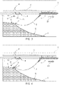
- a laying vessel 1 for laying a pipeline 2 on a bed 3 of a body of water 4 is depicted as a whole.
- the term "pipeline” refers to both a completed pipeline and a pipeline under construction.
- the attached Figures show a laying vessel 1 for S-laying; of course, it is understood that the definition "laying vessel” refers to both a laying vessel for S-laying and a laying vessel for J-laying.
- the laying vessel 1 is equipped to assemble the pipeline 2, progressively launch the pipeline 2, and lay the pipeline 2 as it advances in the direction of travel D1.
- the conformation of the bed 3 is very variable depending on the geographical areas and often there are geological conformations that can induce critical stresses on the pipeline 2.
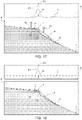
- the case illustrated in the attached Figures shows a bed 3 which comprises a zone 5 close to the shore defined by the so-called “continental shelf” and a zone 6 adjacent to the zone 5 and defined by the so-called “continental slope”.
- the zone 5 and the zone 6 meet in a zone 7, which is characterized by a strong change in slope and, in substance, is the tip of a protrusion of the bed 3 and represents a high criticality for the pipeline 2 as it could cause uncontrolled bends in the pipeline 2.
- the pipeline 2 is laid on the zone 5 (continental shelf) up to the zone 7 and is suspended in the body of water 4 between the zone 7 and the laying vessel 1 above the zone 6.
- the graph C associated with Figure 1 shows the stress on the pipeline 2 according to a predefined scale. Exceeding a threshold value T represents a critical condition for the pipeline 2 which could cause uncontrolled bends in the pipeline 2. In the graph associated with Figure 1 , the graph C is below the threshold value T.
- the laying vessel 1 has moved forward and launched a further portion of the pipeline 2 compared to Figure 1 . Since the portion of the pipeline 2 suspended between the zone 7 and the laying vessel 1 is larger than that of Figure 1 , the graph C correlated to the stress on the pipeline 2 in the zone 7 has a peak P, which corresponds to the zone 7 but is still below the threshold value T.
- the graph C is calculated, through certain algorithms, as a function of the characteristics of the bed 3, the geometrical and structural characteristics of the pipeline 2, and the configuration assumed by the pipeline 2.
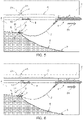
- a support vessel 8 transports a bending machine 9 to the zone 7, and by means of a crane 10 launches the bending machine 9 into the body of water 4 next to the pipeline 2 in proximity to the zone 7.
- the bending machine 9 is clamped to the section of the pipeline 2 which is raised with respect to the zone 5 and in proximity to the zone 7.
- the launching and positioning operations of the bending machine 9 are assisted and controlled by a ROV 11 as shown in Figures 3 and 4 .
- the bending machine 9 performs a series of close bends so as to make a curved section 12 with a curvature concordant with the curvature assumed by the pipeline 2 in proximity to the zone 7 and, in this case, upstream of the zone 7.
- each bend is comprised in the range between 0° 30' and 1° 30', and the step between two successive bends is comprised in the range of 5 - 15 cm.
- the bending machine 9 is advanced stepwise along the pipeline 2 until completion of the curved section 12.
- Each bend and the curved section 12 as a whole are cold and controlled plastic deformations.
- the stresses on the pipeline 2 are progressively reduced and the laying operations can be resumed without generating stresses exceeding the threshold value T.
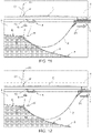
- the bending machine 9 is coupled to the section of the pipeline 2 suspended between the zone 7 and the laying vessel 1 and directly downstream of the zone 7.
- the operations of laying the pipeline 2 can again be interrupted if the stresses on the pipeline 2 are close to the threshold value T.
- a curved section 13 with a curvature concordant with the curvature assumed by the pipeline downstream of the zone 7 is made by a method similar to that described with reference to the curved section 12.
- FIG. 5 to 14 shows a comparison between the graph C1 correlated to the stresses on the pipeline 2 in the absence of the curved section 12 or of the curved sections 12 and 13, and the graph C correlated to the stresses on the pipeline 2 provided with the curved section 12 or with the curved sections 12 and 13.
- the graph C1 has a peak P1 well exceeding the threshold value T, whereas the graph C is entirely below the threshold value T.
- the described method comprises making curved sections 12 and 13 with a curvature and a length such as to allow stresses on the pipeline 2 in accordance with the design parameters.
- the method comprises measuring the angle and the length of each of the curved sections 12 and 13 while they are under construction; and comparing the angle and length of the curved section with reference parameters.
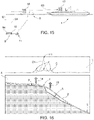
- the bending machine 9 comprises an inclinometer 14 and an odometer 15 for acquiring data from which to detect the angle and the length of the curved section and transmit respective signals S1 and S2 related to the angle and length of the curved section, respectively, to a microprocessor 16, which processes the data and emits a signal S3, which is used to refresh the graph C on a display 17 on board the laying vessel 1, so as to make it possible to evaluate when the operations of launching the pipeline 2 can be resumed without inducing excessive stress on the pipeline.
- the transmission of the signals S1 and S2 between the bending machine 9 and the support vessel 8 is preferably achieved by means of the ROV 11 and the transmission of the signal S3 between the support vessel 8 and the laying vessel 1 is achieved by telecommunication.
- the pipeline 2 is laid both along the zone 5 and along the zone 6.
- the pipeline 2 is locally supported upstream and downstream of the zone 7 by means of supports 18, in this case represented by buoys.
- the supports 18 are installed by means of ROVs (not shown) as the laying operations proceed and keep the stresses below the threshold value T and allow the pipeline 2 to form a very large curved section around the zone 7, with portions of the pipeline 2 raised with respect to the bed 3 both upstream and downstream of position 7.
- the graph C has three peaks P, which correspond to the zone 7 and the positions where the supports 18 are applied.
- the bending machine 9 is coupled to the pipeline 2 upstream of the zone 7 to form the curved section 12 and downstream of the zone 7 to form the curved section 13 in accordance with the methods described with reference to the previous Figures.
- Both the curved sections 12 and 13 have a curvature concordant with the curvature assumed by the pipeline 2 in proximity to the zone 7 and are made by cold plastic deformation.
Landscapes
- Engineering & Computer Science (AREA)
- General Engineering & Computer Science (AREA)
- Mechanical Engineering (AREA)
- Pipeline Systems (AREA)
- Sewage (AREA)
- Supports For Pipes And Cables (AREA)
Claims (16)
- Verfahren zum Verlegen einer Rohrleitung auf dem Grund eines Gewässers, wobei das Verfahren die folgenden Schritte umfasst:- Zusammenbauen einer Rohrleitung (2) auf einem Verlegeschiff (1);- Einbringen der Rohrleitung (2) von dem Verlegeschiff (1);- Identifizieren eines Bereichs (7) des Grunds (3) des Gewässers (4), der Belastungen auslöst, die größer als ein für die Pipeline (2) ermittelter Schwellenwert (T) sind;- abschnittsweises Verlegen der Rohrleitung (2) auf dem Grund (3) des Gewässers (4) durch Vorwärtsbewegen des Verlegeschiffs (1);- Anfertigen zumindest eines gekrümmten Abschnitts (12; 13; 12, 13) entlang der Rohrleitung (2) mittels kontrollierter plastischer Verformung, wobei der gekrümmte Abschnitt (12; 13; 12, 13) übereinstimmend mit der Krümmung ist, die von der Rohrleitung (2) in der Nähe des Bereichs (7) angenommen wird, wenn die Rohrleitung (2) zumindest teilweise auf dem Grund (3) des Gewässers (4) verlegt ist und in Bezug auf den Grund (3) des Gewässers (4) in der Nähe des Bereichs (7) teilweise freischwebend ist;- Erfassen von Signalen (S1, S2), die mit dem Winkel und der Länge des gekrümmten Abschnitts (12; 13; 12, 13) in Wechselbeziehung stehen, während sich der gekrümmte Abschnitt (12; 13; 12, 13) im Aufbau befindet; und- Vergleichen der Signale (S1, S2) mit Referenzparametern.
- Verfahren nach Anspruch 1, und umfassend den Schritt des Übertragens eines Signals (S3) an das Verlegeschiff (1), das sich aus dem Vergleich von dem Winkel und der Länge des gekrümmten Abschnitts (12; 13; 12, 13) mit den Referenzparametern ableitet.
- Verfahren nach Anspruch 2, und umfassend die Schritte des Berechnens eines weiteren Signals (S3) in Abhängigkeit von den Signalen (S1, S2) zum Korrigieren eines Graphen (C), der mit den in der Rohrleitung (2) erzeugten Belastungen in Wechselbeziehung steht; und Darstellen des korrigierten Graphen (C) an Bord des Verlegeschiffs (1).
- Verfahren nach einem beliebigen der vorhergehenden Ansprüche, und umfassend die Schritte des Anfertigens einer Vielzahl von engstufigen Biegungen in der Rohrleitung (2), wobei der gekrümmte Abschnitt (12; 13; 12, 13) eine Abfolge von eng beieinanderliegenden Biegungen umfasst.
- Verfahren nach Anspruch 4, wobei die Ausdehnung jeder Biegung im Bereich zwischen 0° 30' und 1° 30' liegt.
- Verfahren nach einem beliebigen der vorhergehenden Ansprüche, und umfassend die Schritte des Anfertigens zumindest eines ersten gekrümmten Abschnitts (12) vor dem Bereich (7) in Bezug auf die Verlegerichtung der Rohrleitung (2), und zumindest eines zweiten gekrümmten Abschnitts (13) hinter dem Bereich (7).
- Verfahren nach Anspruch 6, und umfassend den Schritt des Anfertigens des ersten und des zweiten gekrümmten Abschnitts (12, 13), wenn sich die Rohrleitung (2) hinter dem Bereich (7) im freischwebenden Zustand zwischen dem Bereich (7) und dem Verlegeschiff (1) befindet.
- Verfahren nach Anspruch 7, und umfassend, nacheinander, die Schritte des Verlegens der Rohrleitung (2) vor dem Bereich (7) bis zu dem Bereich (7) hin; Anfertigen des ersten gekrümmten Abschnitts (12) vor dem Bereich (7); Vorwärtsbewegen des Verlegeschiffs (1), um die Strecke der Rohrleitung (2) hinter dem Bereich (7) abzusenken; Anfertigen des zweiten gekrümmten Abschnitts (13) hinter dem Bereich (7); und Verlegen der Rohrleitung (2) hinter dem Bereich (7).
- Verfahren nach einem beliebigen der Ansprüche 1 bis 6, und umfassend die Schritte des Verlegens der Rohrleitung (2) in dem Bereich (7); Halten eines Abschnitts der Rohrleitung (2) vor dem Bereich (7) mittels mindestens eines ersten Unterstützungsmittels (18) in der Schwebe, um Belastungen auf die Rohrleitung (2) zu reduzieren; und Halten eines Abschnitts der Rohrleitung (2) hinter dem Bereich (7) mittels mindestens eines zweiten Unterstützungsmittels (18) in der Schwebe, um Belastungen auf die Rohrleitung (2) zu reduzieren.
- Verfahren nach Anspruch 9, und umfassend den Schritt des Anfertigens des ersten gekrümmten Abschnitts (12) vor dem Bereich (7) und des zweiten gekrümmten Abschnitts (13) hinter dem Bereich (7); und Entfernen des ersten und des zweiten Unterstützungsmittels (18).
- System zum Verlegen einer Rohrleitung auf dem Grund eines Gewässers, wobei das System Folgendes umfasst:- ein Verlegeschiff (1), das zum Zusammenbauen einer Rohrleitung (2), zum Einbringen der Rohrleitung (2) in das Gewässer (4) und zum abschnittsweisen Verlegen der Rohrleitung (2) auf dem Grund (3) des Gewässers (4) durch Vorwärtsbewegen des Verlegeschiffs (1) ausgestaltet ist;- ein ROV (11), das so ausgestaltet ist, dass es die Position der Rohrleitung (2) auf dem Grund (3) des Gewässers (4) in Bezug auf einen Bereich (7) des Grunds (3) überwacht, der Belastungen verursacht, die höher als ein für die Rohrleitung (2) ermittelter Schwellenwert (T) sind;- eine Biegemaschine (9), die zum Anfertigen zumindest eines gekrümmten Abschnitts (12; 13; 12, 13) entlang der Rohrleitung (2) mittels gesteuerter plastischer Verformung an die Rohrleitung (2) angekoppelt werden soll; wobei der gekrümmte Abschnitt (12; 13; 12, 13) übereinstimmend mit der Krümmung ist, die von der Rohrleitung (2) in der Nähe des Bereichs (7) angenommen wird, wenn die Rohrleitung (2) zumindest teilweise auf dem Grund des Gewässers verlegt ist und in Bezug auf den Grund (3) des Gewässers (4) in der Nähe des Bereichs (7) teilweise freischwebend ist; dadurch gekennzeichnet, dass die Biegemaschine (9) einen Neigungsmesser (14) und einen Wegmesser (15) zum Erfassen jeweiliger Signale (S1, S2) im Zusammenhang mit dem Winkel und der Länge des gekrümmten Abschnitts (12; 13; 12, 13), während sich der gekrümmte Abschnitt (12; 13; 12, 13) im Bau befindet, umfasst; und wobei das System einen Mikroprozessor (17) umfasst, der so ausgestaltet ist, dass er die Signale (S1, S2) mit Referenzparametern vergleicht.
- System nach Anspruch 11, wobei der Mikroprozessor (16) so ausgestaltet ist, dass er ein weiteres Signal (S3) in Abhängigkeit von den Signalen (S1, S2) und den Referenzparametern berechnet und das weitere Signal (S3) zum Korrigieren eines Graphen (C), der mit den in der Rohrleitung (2) erzeugten Belastungen in Wechselbeziehung steht, an das Verlegeschiff (1) überträgt; wobei das Verlegeschiff (1) eine Anzeige (17) zur Darstellung des korrigierten Graphen (C) an Bord des Verlegeschiffs (1) umfasst.
- System nach Anspruch 11 oder 12, wobei die Biegemaschine (9) so ausgestaltet ist, dass sie sich entlang der Rohrleitung (2) vorschiebt und eine Vielzahl von engstufigen Biegungen in der Rohrleitung (2) anfertigt, wobei der gekrümmte Abschnitt (12; 13; 12, 13) eine Abfolge von eng beieinanderliegenden Biegungen umfasst.
- System nach Anspruch 13, wobei die Ausdehnung jeder Biegung im Bereich zwischen 0° 30' und 1° 30' liegt.
- System nach einem beliebigen der Ansprüche 11 bis 14, und umfassend ein Unterstützungsschiff (8), das so ausgestaltet ist, dass es die Biegemaschine (9) in das Gewässer (4) einbringt und die Biegemaschine (9) an gegebenen Stellen entlang der Rohrleitung (2) in dem Gewässer (4) positioniert.
- System nach einem beliebigen der Ansprüche 11 bis 15, und umfassend mindestens ein Unterstützungsmittel (16), das so ausgestaltet ist, dass es zum lokalen und vorübergehenden Stützen der Rohrleitung (2) in der Nähe des Bereichs (7) an der Rohrleitung (2) angekoppelt wird, um Belastungen auf die Rohrleitung (2) vor einem Anfertigen des gekrümmten Abschnitts (12; 13; 12, 13) zu reduzieren.
Applications Claiming Priority (2)
| Application Number | Priority Date | Filing Date | Title |
|---|---|---|---|
| IT201800008658 | 2018-09-17 | ||
| PCT/IB2019/057822 WO2020058848A1 (en) | 2018-09-17 | 2019-09-17 | Method and system for laying a pipeline on the bed of a body of water |
Publications (2)
| Publication Number | Publication Date |
|---|---|
| EP3853508A1 EP3853508A1 (de) | 2021-07-28 |
| EP3853508B1 true EP3853508B1 (de) | 2022-08-31 |
Family
ID=64557008
Family Applications (1)
| Application Number | Title | Priority Date | Filing Date |
|---|---|---|---|
| EP19787078.5A Active EP3853508B1 (de) | 2018-09-17 | 2019-09-17 | Verfahren und system zur verlegung einer rohrleitung auf dem boden eines gewässers |
Country Status (8)
| Country | Link |
|---|---|
| US (1) | US11578817B2 (de) |
| EP (1) | EP3853508B1 (de) |
| AU (1) | AU2019341691B2 (de) |
| BR (1) | BR112021005006B1 (de) |
| CY (1) | CY1125605T1 (de) |
| ES (1) | ES2926651T3 (de) |
| SA (1) | SA521421467B1 (de) |
| WO (1) | WO2020058848A1 (de) |
Families Citing this family (1)
| Publication number | Priority date | Publication date | Assignee | Title |
|---|---|---|---|---|
| US12228931B2 (en) * | 2023-05-22 | 2025-02-18 | Navico, Inc. | Systems and methods for managing positions of watercrafts |
Family Cites Families (9)
| Publication number | Priority date | Publication date | Assignee | Title |
|---|---|---|---|---|
| EP0963798A1 (de) * | 1998-05-20 | 1999-12-15 | Saipem S.p.A. | Rohrbiegemaschine geeignet zum Betrieb auf dem Meeresboden |
| US7963721B2 (en) * | 2004-09-21 | 2011-06-21 | Kellogg Brown & Root Llc | Distributed buoyancy subsea pipeline apparatus and method |
| US20070081862A1 (en) * | 2005-10-07 | 2007-04-12 | Heerema Marine Contractors Nederland B.V. | Pipeline assembly comprising an anchoring device and method for installing a pipeline assembly comprising an anchoring device |
| US8562255B2 (en) * | 2009-06-24 | 2013-10-22 | Tor Persson | Bending restrictor assembly for use with a pipeline section |
| US8128129B2 (en) | 2009-07-15 | 2012-03-06 | Oil States Industries, Inc. | Double-ended flexible pipe joint having stacked co-axial primary and secondary annular elastomeric flex elements |
| DK2691683T3 (en) * | 2011-03-31 | 2017-01-09 | The Safer Plug Company Ltd | AUTOMATICALLY DEFENDING STOPPING PIPELINE INSULATION TOOL |
| US10508414B2 (en) * | 2014-09-25 | 2019-12-17 | Saipem S.P.A. | System and method for laying an underwater pipeline on a bed of a body of water |
| ITUB20152332A1 (it) | 2015-07-21 | 2017-01-21 | Saipem Spa | Dispositivo di giunzione di una condotta per cambi di pendenza di fondali, condotta continua comprendente detto dispositivo e metodo di giunzione |
| GB201702860D0 (en) * | 2017-02-22 | 2017-04-05 | Optical Metrology Services Ltd | Apparatus for monitoring an elongate element |
-
2019
- 2019-09-17 EP EP19787078.5A patent/EP3853508B1/de active Active
- 2019-09-17 WO PCT/IB2019/057822 patent/WO2020058848A1/en not_active Ceased
- 2019-09-17 ES ES19787078T patent/ES2926651T3/es active Active
- 2019-09-17 BR BR112021005006-0A patent/BR112021005006B1/pt active IP Right Grant
- 2019-09-17 US US17/275,564 patent/US11578817B2/en active Active
- 2019-09-17 AU AU2019341691A patent/AU2019341691B2/en active Active
-
2021
- 2021-03-15 SA SA521421467A patent/SA521421467B1/ar unknown
-
2022
- 2022-09-14 CY CY20221100611T patent/CY1125605T1/el unknown
Also Published As
| Publication number | Publication date |
|---|---|
| US20210364103A1 (en) | 2021-11-25 |
| US11578817B2 (en) | 2023-02-14 |
| AU2019341691A1 (en) | 2021-05-20 |
| ES2926651T3 (es) | 2022-10-27 |
| SA521421467B1 (ar) | 2022-12-20 |
| BR112021005006B1 (pt) | 2024-01-09 |
| EP3853508A1 (de) | 2021-07-28 |
| CY1125605T1 (el) | 2026-02-25 |
| AU2019341691B2 (en) | 2025-04-24 |
| WO2020058848A1 (en) | 2020-03-26 |
| BR112021005006A2 (pt) | 2021-06-08 |
Similar Documents
| Publication | Publication Date | Title |
|---|---|---|
| US20120114420A1 (en) | Group and method for laying and burying pipelines at the seafloor | |
| DK2691683T3 (en) | AUTOMATICALLY DEFENDING STOPPING PIPELINE INSULATION TOOL | |
| NO343940B1 (en) | Deployment and direct tie-in of subsea pipelines | |
| EP3853508B1 (de) | Verfahren und system zur verlegung einer rohrleitung auf dem boden eines gewässers | |
| AU2019371809B2 (en) | Installation of subsea pipelines | |
| WO2016103038A1 (en) | Improving the bending behaviour of mechanically-lined rigid pipe | |
| OA20132A (en) | Method and system for laying a pipeline on the bed of a body of water. | |
| EP3701178B1 (de) | Ausgrabungsvorrichtung und eingegrabenes kabel oder rohrleitung | |
| US10508414B2 (en) | System and method for laying an underwater pipeline on a bed of a body of water | |
| EP4111081B1 (de) | Knickminderung in unterwasserleitungen | |
| EP4388234B1 (de) | Verfahren zum verlegen einer anordnung aus einem flexiblen länglichen element und einem starren zubehör zum eintauchen in wasser von einem installationsschiff, baugruppe für dessen unterwasserinstallation | |
| Barnes et al. | Installation of the Residual Curvature Method for Reeled Pipe in Pipe | |
| OA20557A (en) | Device for connecting an underwater pipe to a fixed structure and associated connection method. | |
| WO2023213951A1 (en) | A bend limiter, a method of producing the bend limiter and an installation comprising the bend limiter | |
| Hao et al. | Design and installation of subsea jumper with CRA liner | |
| WO2023233127A1 (en) | A sag bend support device for an underwater pipe, and a pipe laying system comprising the same | |
| Bhargav et al. | Beachpull Installation of Long Pipelines and Cables |
Legal Events
| Date | Code | Title | Description |
|---|---|---|---|
| STAA | Information on the status of an ep patent application or granted ep patent |
Free format text: STATUS: UNKNOWN |
|
| STAA | Information on the status of an ep patent application or granted ep patent |
Free format text: STATUS: THE INTERNATIONAL PUBLICATION HAS BEEN MADE |
|
| PUAI | Public reference made under article 153(3) epc to a published international application that has entered the european phase |
Free format text: ORIGINAL CODE: 0009012 |
|
| STAA | Information on the status of an ep patent application or granted ep patent |
Free format text: STATUS: REQUEST FOR EXAMINATION WAS MADE |
|
| 17P | Request for examination filed |
Effective date: 20210322 |
|
| AK | Designated contracting states |
Kind code of ref document: A1 Designated state(s): AL AT BE BG CH CY CZ DE DK EE ES FI FR GB GR HR HU IE IS IT LI LT LU LV MC MK MT NL NO PL PT RO RS SE SI SK SM TR |
|
| DAV | Request for validation of the european patent (deleted) | ||
| DAX | Request for extension of the european patent (deleted) | ||
| GRAP | Despatch of communication of intention to grant a patent |
Free format text: ORIGINAL CODE: EPIDOSNIGR1 |
|
| STAA | Information on the status of an ep patent application or granted ep patent |
Free format text: STATUS: GRANT OF PATENT IS INTENDED |
|
| INTG | Intention to grant announced |
Effective date: 20220324 |
|
| GRAS | Grant fee paid |
Free format text: ORIGINAL CODE: EPIDOSNIGR3 |
|
| GRAA | (expected) grant |
Free format text: ORIGINAL CODE: 0009210 |
|
| STAA | Information on the status of an ep patent application or granted ep patent |
Free format text: STATUS: THE PATENT HAS BEEN GRANTED |
|
| AK | Designated contracting states |
Kind code of ref document: B1 Designated state(s): AL AT BE BG CH CY CZ DE DK EE ES FI FR GB GR HR HU IE IS IT LI LT LU LV MC MK MT NL NO PL PT RO RS SE SI SK SM TR |
|
| REG | Reference to a national code |
Ref country code: CH Ref legal event code: EP Ref country code: GB Ref legal event code: FG4D |
|
| REG | Reference to a national code |
Ref country code: RO Ref legal event code: EPE Ref country code: AT Ref legal event code: REF Ref document number: 1515522 Country of ref document: AT Kind code of ref document: T Effective date: 20220915 |
|
| REG | Reference to a national code |
Ref country code: DE Ref legal event code: R096 Ref document number: 602019019055 Country of ref document: DE |
|
| REG | Reference to a national code |
Ref country code: IE Ref legal event code: FG4D |
|
| REG | Reference to a national code |
Ref country code: GR Ref legal event code: EP Ref document number: 20220401802 Country of ref document: GR Effective date: 20221010 |
|
| REG | Reference to a national code |
Ref country code: ES Ref legal event code: FG2A Ref document number: 2926651 Country of ref document: ES Kind code of ref document: T3 Effective date: 20221027 |
|
| REG | Reference to a national code |
Ref country code: NO Ref legal event code: T2 Effective date: 20220831 |
|
| REG | Reference to a national code |
Ref country code: LT Ref legal event code: MG9D |
|
| RAP4 | Party data changed (patent owner data changed or rights of a patent transferred) |
Owner name: SAIPEM S.P.A. |
|
| REG | Reference to a national code |
Ref country code: NL Ref legal event code: MP Effective date: 20220831 |
|
| PG25 | Lapsed in a contracting state [announced via postgrant information from national office to epo] |
Ref country code: SE Free format text: LAPSE BECAUSE OF FAILURE TO SUBMIT A TRANSLATION OF THE DESCRIPTION OR TO PAY THE FEE WITHIN THE PRESCRIBED TIME-LIMIT Effective date: 20220831 Ref country code: RS Free format text: LAPSE BECAUSE OF FAILURE TO SUBMIT A TRANSLATION OF THE DESCRIPTION OR TO PAY THE FEE WITHIN THE PRESCRIBED TIME-LIMIT Effective date: 20220831 Ref country code: LV Free format text: LAPSE BECAUSE OF FAILURE TO SUBMIT A TRANSLATION OF THE DESCRIPTION OR TO PAY THE FEE WITHIN THE PRESCRIBED TIME-LIMIT Effective date: 20220831 Ref country code: LT Free format text: LAPSE BECAUSE OF FAILURE TO SUBMIT A TRANSLATION OF THE DESCRIPTION OR TO PAY THE FEE WITHIN THE PRESCRIBED TIME-LIMIT Effective date: 20220831 Ref country code: FI Free format text: LAPSE BECAUSE OF FAILURE TO SUBMIT A TRANSLATION OF THE DESCRIPTION OR TO PAY THE FEE WITHIN THE PRESCRIBED TIME-LIMIT Effective date: 20220831 |
|
| REG | Reference to a national code |
Ref country code: AT Ref legal event code: MK05 Ref document number: 1515522 Country of ref document: AT Kind code of ref document: T Effective date: 20220831 |
|
| PG25 | Lapsed in a contracting state [announced via postgrant information from national office to epo] |
Ref country code: PL Free format text: LAPSE BECAUSE OF FAILURE TO SUBMIT A TRANSLATION OF THE DESCRIPTION OR TO PAY THE FEE WITHIN THE PRESCRIBED TIME-LIMIT Effective date: 20220831 Ref country code: IS Free format text: LAPSE BECAUSE OF FAILURE TO SUBMIT A TRANSLATION OF THE DESCRIPTION OR TO PAY THE FEE WITHIN THE PRESCRIBED TIME-LIMIT Effective date: 20221231 Ref country code: HR Free format text: LAPSE BECAUSE OF FAILURE TO SUBMIT A TRANSLATION OF THE DESCRIPTION OR TO PAY THE FEE WITHIN THE PRESCRIBED TIME-LIMIT Effective date: 20220831 |
|
| REG | Reference to a national code |
Ref country code: DE Ref legal event code: R119 Ref document number: 602019019055 Country of ref document: DE |
|
| PG25 | Lapsed in a contracting state [announced via postgrant information from national office to epo] |
Ref country code: SM Free format text: LAPSE BECAUSE OF FAILURE TO SUBMIT A TRANSLATION OF THE DESCRIPTION OR TO PAY THE FEE WITHIN THE PRESCRIBED TIME-LIMIT Effective date: 20220831 Ref country code: PT Free format text: LAPSE BECAUSE OF FAILURE TO SUBMIT A TRANSLATION OF THE DESCRIPTION OR TO PAY THE FEE WITHIN THE PRESCRIBED TIME-LIMIT Effective date: 20230102 Ref country code: DK Free format text: LAPSE BECAUSE OF FAILURE TO SUBMIT A TRANSLATION OF THE DESCRIPTION OR TO PAY THE FEE WITHIN THE PRESCRIBED TIME-LIMIT Effective date: 20220831 Ref country code: CZ Free format text: LAPSE BECAUSE OF FAILURE TO SUBMIT A TRANSLATION OF THE DESCRIPTION OR TO PAY THE FEE WITHIN THE PRESCRIBED TIME-LIMIT Effective date: 20220831 Ref country code: AT Free format text: LAPSE BECAUSE OF FAILURE TO SUBMIT A TRANSLATION OF THE DESCRIPTION OR TO PAY THE FEE WITHIN THE PRESCRIBED TIME-LIMIT Effective date: 20220831 |
|
| REG | Reference to a national code |
Ref country code: CH Ref legal event code: PL |
|
| REG | Reference to a national code |
Ref country code: BE Ref legal event code: MM Effective date: 20220930 |
|
| PG25 | Lapsed in a contracting state [announced via postgrant information from national office to epo] |
Ref country code: SK Free format text: LAPSE BECAUSE OF FAILURE TO SUBMIT A TRANSLATION OF THE DESCRIPTION OR TO PAY THE FEE WITHIN THE PRESCRIBED TIME-LIMIT Effective date: 20220831 Ref country code: MC Free format text: LAPSE BECAUSE OF FAILURE TO SUBMIT A TRANSLATION OF THE DESCRIPTION OR TO PAY THE FEE WITHIN THE PRESCRIBED TIME-LIMIT Effective date: 20220831 Ref country code: EE Free format text: LAPSE BECAUSE OF FAILURE TO SUBMIT A TRANSLATION OF THE DESCRIPTION OR TO PAY THE FEE WITHIN THE PRESCRIBED TIME-LIMIT Effective date: 20220831 |
|
| P01 | Opt-out of the competence of the unified patent court (upc) registered |
Effective date: 20230420 |
|
| PG25 | Lapsed in a contracting state [announced via postgrant information from national office to epo] |
Ref country code: NL Free format text: LAPSE BECAUSE OF FAILURE TO SUBMIT A TRANSLATION OF THE DESCRIPTION OR TO PAY THE FEE WITHIN THE PRESCRIBED TIME-LIMIT Effective date: 20220831 Ref country code: LU Free format text: LAPSE BECAUSE OF NON-PAYMENT OF DUE FEES Effective date: 20220917 Ref country code: AL Free format text: LAPSE BECAUSE OF FAILURE TO SUBMIT A TRANSLATION OF THE DESCRIPTION OR TO PAY THE FEE WITHIN THE PRESCRIBED TIME-LIMIT Effective date: 20220831 |
|
| PLBE | No opposition filed within time limit |
Free format text: ORIGINAL CODE: 0009261 |
|
| STAA | Information on the status of an ep patent application or granted ep patent |
Free format text: STATUS: NO OPPOSITION FILED WITHIN TIME LIMIT |
|
| PG25 | Lapsed in a contracting state [announced via postgrant information from national office to epo] |
Ref country code: LI Free format text: LAPSE BECAUSE OF NON-PAYMENT OF DUE FEES Effective date: 20220930 Ref country code: IE Free format text: LAPSE BECAUSE OF NON-PAYMENT OF DUE FEES Effective date: 20220917 Ref country code: DE Free format text: LAPSE BECAUSE OF NON-PAYMENT OF DUE FEES Effective date: 20230401 Ref country code: CH Free format text: LAPSE BECAUSE OF NON-PAYMENT OF DUE FEES Effective date: 20220930 |
|
| 26N | No opposition filed |
Effective date: 20230601 |
|
| PG25 | Lapsed in a contracting state [announced via postgrant information from national office to epo] |
Ref country code: SI Free format text: LAPSE BECAUSE OF FAILURE TO SUBMIT A TRANSLATION OF THE DESCRIPTION OR TO PAY THE FEE WITHIN THE PRESCRIBED TIME-LIMIT Effective date: 20220831 |
|
| PG25 | Lapsed in a contracting state [announced via postgrant information from national office to epo] |
Ref country code: BE Free format text: LAPSE BECAUSE OF NON-PAYMENT OF DUE FEES Effective date: 20220930 |
|
| P02 | Opt-out of the competence of the unified patent court (upc) changed |
Effective date: 20231123 |
|
| PG25 | Lapsed in a contracting state [announced via postgrant information from national office to epo] |
Ref country code: MK Free format text: LAPSE BECAUSE OF FAILURE TO SUBMIT A TRANSLATION OF THE DESCRIPTION OR TO PAY THE FEE WITHIN THE PRESCRIBED TIME-LIMIT Effective date: 20220831 Ref country code: HU Free format text: LAPSE BECAUSE OF FAILURE TO SUBMIT A TRANSLATION OF THE DESCRIPTION OR TO PAY THE FEE WITHIN THE PRESCRIBED TIME-LIMIT; INVALID AB INITIO Effective date: 20190917 |
|
| PGFP | Annual fee paid to national office [announced via postgrant information from national office to epo] |
Ref country code: NO Payment date: 20250917 Year of fee payment: 7 Ref country code: GR Payment date: 20250923 Year of fee payment: 7 |
|
| PGFP | Annual fee paid to national office [announced via postgrant information from national office to epo] |
Ref country code: TR Payment date: 20250904 Year of fee payment: 7 Ref country code: IT Payment date: 20250922 Year of fee payment: 7 |
|
| PGFP | Annual fee paid to national office [announced via postgrant information from national office to epo] |
Ref country code: BG Payment date: 20250925 Year of fee payment: 7 Ref country code: GB Payment date: 20250923 Year of fee payment: 7 |
|
| PGFP | Annual fee paid to national office [announced via postgrant information from national office to epo] |
Ref country code: FR Payment date: 20250925 Year of fee payment: 7 |
|
| PGFP | Annual fee paid to national office [announced via postgrant information from national office to epo] |
Ref country code: MT Payment date: 20250925 Year of fee payment: 7 |
|
| PGFP | Annual fee paid to national office [announced via postgrant information from national office to epo] |
Ref country code: RO Payment date: 20250909 Year of fee payment: 7 |
|
| PGFP | Annual fee paid to national office [announced via postgrant information from national office to epo] |
Ref country code: CY Payment date: 20250908 Year of fee payment: 7 |
|
| PGFP | Annual fee paid to national office [announced via postgrant information from national office to epo] |
Ref country code: ES Payment date: 20251015 Year of fee payment: 7 |