EP3853466B1 - Turboreaktor mit einer leistungs-versorgungsvorrichtung - Google Patents
Turboreaktor mit einer leistungs-versorgungsvorrichtung Download PDFInfo
- Publication number
- EP3853466B1 EP3853466B1 EP19790680.3A EP19790680A EP3853466B1 EP 3853466 B1 EP3853466 B1 EP 3853466B1 EP 19790680 A EP19790680 A EP 19790680A EP 3853466 B1 EP3853466 B1 EP 3853466B1
- Authority
- EP
- European Patent Office
- Prior art keywords
- turbine
- compressor
- reduction gear
- ratio
- power supply
- Prior art date
- Legal status (The legal status is an assumption and is not a legal conclusion. Google has not performed a legal analysis and makes no representation as to the accuracy of the status listed.)
- Active
Links
Images

Classifications
-
- F—MECHANICAL ENGINEERING; LIGHTING; HEATING; WEAPONS; BLASTING
- F02—COMBUSTION ENGINES; HOT-GAS OR COMBUSTION-PRODUCT ENGINE PLANTS
- F02C—GAS-TURBINE PLANTS; AIR INTAKES FOR JET-PROPULSION PLANTS; CONTROLLING FUEL SUPPLY IN AIR-BREATHING JET-PROPULSION PLANTS
- F02C7/00—Features, components parts, details or accessories, not provided for in, or of interest apart form groups F02C1/00 - F02C6/00; Air intakes for jet-propulsion plants
- F02C7/32—Arrangement, mounting, or driving, of auxiliaries
-
- F—MECHANICAL ENGINEERING; LIGHTING; HEATING; WEAPONS; BLASTING
- F01—MACHINES OR ENGINES IN GENERAL; ENGINE PLANTS IN GENERAL; STEAM ENGINES
- F01D—NON-POSITIVE DISPLACEMENT MACHINES OR ENGINES, e.g. STEAM TURBINES
- F01D15/00—Adaptations of machines or engines for special use; Combinations of engines with devices driven thereby
- F01D15/10—Adaptations for driving, or combinations with, electric generators
-
- F—MECHANICAL ENGINEERING; LIGHTING; HEATING; WEAPONS; BLASTING
- F02—COMBUSTION ENGINES; HOT-GAS OR COMBUSTION-PRODUCT ENGINE PLANTS
- F02C—GAS-TURBINE PLANTS; AIR INTAKES FOR JET-PROPULSION PLANTS; CONTROLLING FUEL SUPPLY IN AIR-BREATHING JET-PROPULSION PLANTS
- F02C6/00—Plural gas-turbine plants; Combinations of gas-turbine plants with other apparatus; Adaptations of gas-turbine plants for special use
- F02C6/20—Adaptations of gas-turbine plants for driving vehicles
-
- F—MECHANICAL ENGINEERING; LIGHTING; HEATING; WEAPONS; BLASTING
- F02—COMBUSTION ENGINES; HOT-GAS OR COMBUSTION-PRODUCT ENGINE PLANTS
- F02C—GAS-TURBINE PLANTS; AIR INTAKES FOR JET-PROPULSION PLANTS; CONTROLLING FUEL SUPPLY IN AIR-BREATHING JET-PROPULSION PLANTS
- F02C7/00—Features, components parts, details or accessories, not provided for in, or of interest apart form groups F02C1/00 - F02C6/00; Air intakes for jet-propulsion plants
- F02C7/36—Power transmission arrangements between the different shafts of the gas turbine plant, or between the gas-turbine plant and the power user
-
- F—MECHANICAL ENGINEERING; LIGHTING; HEATING; WEAPONS; BLASTING
- F02—COMBUSTION ENGINES; HOT-GAS OR COMBUSTION-PRODUCT ENGINE PLANTS
- F02K—JET-PROPULSION PLANTS
- F02K3/00—Plants including a gas turbine driving a compressor or a ducted fan
-
- F—MECHANICAL ENGINEERING; LIGHTING; HEATING; WEAPONS; BLASTING
- F02—COMBUSTION ENGINES; HOT-GAS OR COMBUSTION-PRODUCT ENGINE PLANTS
- F02K—JET-PROPULSION PLANTS
- F02K3/00—Plants including a gas turbine driving a compressor or a ducted fan
- F02K3/02—Plants including a gas turbine driving a compressor or a ducted fan in which part of the working fluid by-passes the turbine and combustion chamber
- F02K3/04—Plants including a gas turbine driving a compressor or a ducted fan in which part of the working fluid by-passes the turbine and combustion chamber the plant including ducted fans, i.e. fans with high volume, low pressure outputs, for augmenting the jet thrust, e.g. of double-flow type
- F02K3/06—Plants including a gas turbine driving a compressor or a ducted fan in which part of the working fluid by-passes the turbine and combustion chamber the plant including ducted fans, i.e. fans with high volume, low pressure outputs, for augmenting the jet thrust, e.g. of double-flow type with front fan
-
- F—MECHANICAL ENGINEERING; LIGHTING; HEATING; WEAPONS; BLASTING
- F02—COMBUSTION ENGINES; HOT-GAS OR COMBUSTION-PRODUCT ENGINE PLANTS
- F02K—JET-PROPULSION PLANTS
- F02K5/00—Plants including an engine, other than a gas turbine, driving a compressor or a ducted fan
-
- B—PERFORMING OPERATIONS; TRANSPORTING
- B64—AIRCRAFT; AVIATION; COSMONAUTICS
- B64D—EQUIPMENT FOR FITTING IN OR TO AIRCRAFT; FLIGHT SUITS; PARACHUTES; ARRANGEMENT OR MOUNTING OF POWER PLANTS OR PROPULSION TRANSMISSIONS IN AIRCRAFT
- B64D27/00—Arrangement or mounting of power plants in aircraft; Aircraft characterised by the type or position of power plants
- B64D27/02—Aircraft characterised by the type or position of power plants
- B64D27/026—Aircraft characterised by the type or position of power plants comprising different types of power plants, e.g. combination of a piston engine and a gas-turbine
-
- F—MECHANICAL ENGINEERING; LIGHTING; HEATING; WEAPONS; BLASTING
- F05—INDEXING SCHEMES RELATING TO ENGINES OR PUMPS IN VARIOUS SUBCLASSES OF CLASSES F01-F04
- F05D—INDEXING SCHEME FOR ASPECTS RELATING TO NON-POSITIVE-DISPLACEMENT MACHINES OR ENGINES, GAS-TURBINES OR JET-PROPULSION PLANTS
- F05D2220/00—Application
- F05D2220/30—Application in turbines
- F05D2220/32—Application in turbines in gas turbines
- F05D2220/323—Application in turbines in gas turbines for aircraft propulsion, e.g. jet engines
-
- F—MECHANICAL ENGINEERING; LIGHTING; HEATING; WEAPONS; BLASTING
- F05—INDEXING SCHEMES RELATING TO ENGINES OR PUMPS IN VARIOUS SUBCLASSES OF CLASSES F01-F04
- F05D—INDEXING SCHEME FOR ASPECTS RELATING TO NON-POSITIVE-DISPLACEMENT MACHINES OR ENGINES, GAS-TURBINES OR JET-PROPULSION PLANTS
- F05D2220/00—Application
- F05D2220/70—Application in combination with
- F05D2220/76—Application in combination with an electrical generator
-
- F—MECHANICAL ENGINEERING; LIGHTING; HEATING; WEAPONS; BLASTING
- F05—INDEXING SCHEMES RELATING TO ENGINES OR PUMPS IN VARIOUS SUBCLASSES OF CLASSES F01-F04
- F05D—INDEXING SCHEME FOR ASPECTS RELATING TO NON-POSITIVE-DISPLACEMENT MACHINES OR ENGINES, GAS-TURBINES OR JET-PROPULSION PLANTS
- F05D2260/00—Function
- F05D2260/40—Transmission of power
- F05D2260/403—Transmission of power through the shape of the drive components
- F05D2260/4031—Transmission of power through the shape of the drive components as in toothed gearing
- F05D2260/40311—Transmission of power through the shape of the drive components as in toothed gearing of the epicyclical, planetary or differential type
-
- Y—GENERAL TAGGING OF NEW TECHNOLOGICAL DEVELOPMENTS; GENERAL TAGGING OF CROSS-SECTIONAL TECHNOLOGIES SPANNING OVER SEVERAL SECTIONS OF THE IPC; TECHNICAL SUBJECTS COVERED BY FORMER USPC CROSS-REFERENCE ART COLLECTIONS [XRACs] AND DIGESTS
- Y02—TECHNOLOGIES OR APPLICATIONS FOR MITIGATION OR ADAPTATION AGAINST CLIMATE CHANGE
- Y02T—CLIMATE CHANGE MITIGATION TECHNOLOGIES RELATED TO TRANSPORTATION
- Y02T50/00—Aeronautics or air transport
- Y02T50/60—Efficient propulsion technologies, e.g. for aircraft
Definitions
- This presentation concerns the field of aircraft, and more particularly a turbojet engine which can be used for aeronautical propulsion.
- the present disclosure relates to a dual-flow turbojet engine according to claim 1, comprising a fan, a casing arranged downstream of the fan and separating a primary flow path from a secondary flow path, a compressor, a combustion chamber and a turbine being arranged in the primary flow path, the turbojet engine comprising a differential transmission coupled to the turbine, and a power supply device configured to provide additional power to that provided by the turbine to drive the compressor.
- the axis of the turbojet engine is referred to as its axis of symmetry or quasi-symmetry, which forms the axis of rotation of the compressor and the turbine.
- the axial direction corresponds to the direction of the axis of the turbojet engine and a radial direction is a direction perpendicular to this axis and intersecting this axis.
- an axial plane is a plane containing the axis of the turbojet engine and a radial plane is a plane perpendicular to this axis.
- a circumference is understood to be a circle belonging to a radial plane and whose center belongs to the axis of the turbojet engine.
- a tangential or circumferential direction is a direction tangent to a circumference; it is perpendicular to the axis of the turbojet engine but does not pass through the axis.
- the adjectives forward and aft are used in reference to the axial direction, it being understood that the inlet of the turbojet engine is located on the front side of the turbojet engine, while its outlet is located on the rear side.
- the adjectives upstream and downstream are used in reference to the normal flow direction of gases in the turbojet engine.
- interior and exterior are used in reference to a radial direction so that the interior part of an element is, in a radial direction, closer to the axis of the turbojet than the exterior part of the same element.
- the turbojet is said to be dual-flow in that it comprises a primary vein receiving a primary flow and a secondary vein receiving a secondary flow.
- the casing separating the primary vein and the secondary vein is sometimes called the internal casing.
- the differential transmission is coupled to the turbine, i.e. there is a functional, possibly permanent, connection between the turbine and the differential transmission.
- the differential transmission can be configured to drive the blower and/or the compressor, using mechanical energy provided by the turbine.
- Differential transmission is a power transmission allowing the speed ratio and/or torque to be modified between at least one input, in this case the turbine, and at least one output, in this case the fan and/or the compressor.
- the differential transmission may have a transmission ratio of less than one, in which case it is sometimes referred to as a reduction system, but also greater than one, depending on what is considered to be the input or output, in which case it is sometimes referred to as a multiplier system.
- the differential transmission may be electromechanical or purely mechanical.
- the turbojet engine may be a single-spool turbojet engine.
- a single-spool turbojet engine comprises a single rotating assembly, connecting one or more compressors to one or more turbines via a common kinematics, which does not mean that all the components rotate at the same speed but that their rotations are linked.
- a twin-spool turbojet engine comprises two kinematically independent rotating assemblies, each of these assemblies connecting its own compressors and turbines via its own kinematics and independent of that of the other assembly.
- the single spool comprises a compressor and a turbine.
- this presentation proposes to implement a single-spool turbojet.
- Such an architecture makes it possible to greatly simplify the turbojet, for example by eliminating complex components such as shafts, bearings and supports, and to reduce its mass and cost.
- the turbojet engine comprises a power supply device configured to provide additional power to that provided by the turbine to drive the compressor, it is possible, depending on the speed, to operate the compressor in a desired operating range whereas the turbine alone, in the considered speed, in particular at low speed, would not allow operation in this range.
- the performance of the turbojet is of a level comparable to that of existing turbojets elsewhere, whatever the speed of the turbojet, or else has a much better performance/cost ratio than an existing turbojet.
- the turbojet engine further comprises a control unit configured to control the power supply device as a function of a rotational speed of the turbine.
- the power supply device can be controlled as a function of the speed of the turbojet engine. This makes it possible to finely adapt the parameters of the turbojet engine and to optimize the operation of the turbojet engine.
- the power supply device comprises an electric motor configured to rotate the compressor.
- the power supply device can be controlled very flexibly, depending on the power requirements, in particular continuously over a range covering zero power up to the maximum design power of the power supply device.
- the power supply device comprises an electric generator configured to be driven by the turbine.
- the electric generator may be configured to power the aforementioned electric motor, directly or via electricity storage means.
- the turbojet comprises electricity storage means electrically connected to the electric motor or to the electric generator.
- the turbine may drive the electric generator so that excess mechanical power is stored, in electrical form, in the electricity storage means.
- the compressor may be driven by the turbine and the electric motor, the electric motor drawing its energy from the electricity storage means.
- the electricity storage means could be recharged using a power supply external to the turbojet engine.
- the power supply device includes a connector configured to be connected to an external power supply.
- the power supply device comprises a variable mechanical transmission coupled on the one hand to the compressor shaft, on the other hand to the turbine shaft.
- the variable mechanical transmission makes it possible to draw power from the turbine to drive the compressor, said power being able to be regulated, for example according to the speed of the turbojet engine.
- the variable mechanical transmission can be connected or disconnected from the compressor and/or the turbine.
- the variable mechanical transmission can transmit a fixed or variable proportion of the power of the turbine to the compressor.
- the variable mechanical transmission can comprise any of the following elements: a clutch, a gearbox, a variator, etc.
- the power supply device comprises an electromagnetic transmission coupled to the compressor shaft and the turbine shaft.
- the electromagnetic transmission may be, for example, a magnetic gear transmission.
- An electromagnetic transmission having many advantages, including the absence of mechanical fatigue, lubrication, losses due to mechanical contacts, noise, as well as very high efficiency.
- the maximum additional power provided by the power supply device is greater than 1.5 megawatts (MW). Such maximum additional power is useful for compensating for power not provided by the turbine during certain turbojet engine speeds.
- the power supply device is configured to be deactivated when the rotational speed of the turbine is greater than 95% of the maximum nominal rotational speed of the turbine.
- the power supply device can be configured to be deactivated when the rotational speed of the turbine is sufficient to drive the compressor alone at a reduced speed, of at least 50% of the nominal speed, preferably at least 70%.
- the power supply device can be configured to be activated when the rotational speed of the turbine is insufficient to drive the compressor alone at a reduced speed of at least 50% of the nominal speed, preferably at least 70%.
- the present disclosure also relates to a single-spool dual-flow turbojet engine, comprising a fan, a casing arranged downstream of the fan and separating a primary stream from a secondary stream, a compressor, a combustion chamber and a turbine being arranged in the primary stream, the turbojet engine comprising a differential transmission coupled to the turbine, in which the dilution ratio between the secondary stream and the primary stream is greater than or equal to 12.
- bypass ratio is the ratio of the air flow entering the secondary vein to the air flow entering the primary vein.
- BPR bypass ratio
- bypass ratio between the secondary stream and the main stream is greater than or equal to 12
- the performance of the turbojet engine is further improved.
- a bypass ratio can be obtained within the framework of a subsonic ejection speed at the outlet of the turbojet engine, preferably between Mach 0.8 and Mach 1 at the throat of the ejection nozzle, for a corresponding aircraft speed between Mach 0.7 and Mach 0.9.
- the differential transmission includes a first reducer configured to change the rotational speed transmission ratio between the turbine and the fan and a second reducer configured to change the rotational speed transmission ratio between the turbine and the compressor.
- the rotation of the fan can be decoupled from the rotation of the compressor, which makes it possible to have different rotation speeds for these two components.
- This makes it possible to maintain the rotation speed of the compressor at a certain level while reducing the rotation speed of the fan.
- the rotation speed of the fan determines the tangential speed of the radially external part of the fan blades, also called the blade head.
- the speed of the blade head must respect certain constraints, in particular remain subsonic, for example less than or equal to 310 meters per second (m/s). Consequently, being able to reduce the rotation speed of the fan allows, at equal blade tip speed, to increase the diameter of the fan. This results in even better performance for the turbojet.
- the second reducer is coupled to an output of the first reducer.
- the first reducer is a differential reducer having an input wheel rotationally connected to the turbine, a first output wheel rotationally connected to the fan, a second output wheel rotationally connected to an input wheel of the second reducer, and the second reducer is an epicyclic reducer having an output wheel rotationally connected to the compressor.
- the ratio of the number of teeth of the first output wheel of the first reducer to the number of teeth of the input wheel of the first reducer is greater than 1. This ratio may be greater than 1.2, more preferably greater than 1.4. In addition, this ratio may be less than 1.8, more preferably less than 1.6. This ratio may be approximately equal to 1.5. In the case of nominal operation, the first reducer is therefore configured to provide the blower with a lower rotation speed than that provided to the compressor.
- the ratio of the number of teeth of the crown of the second reducer to the number of teeth of the output wheel of the second reducer is greater than 2.
- the crown of the second reducer may be fixed relative to the internal casing of the turbojet engine. This ratio makes it possible to increase the rotational speed of the compressor relative to the speed provided at the input of the second reducer by the first reducer.
- This ratio may be greater than 5, preferably even greater than 6.
- this ratio may be less than 9, preferably even less than 8. This ratio may be approximately equal to 7.
- the second reducer has a transmission ratio greater than 3.
- the transmission ratio is the ratio of the rotational speed of the output wheel to the rotational speed of the input wheel.
- the rotational speed of the planet carrier is considered, which corresponds to the speed of revolution of the satellites around the sun gear and not the rotational speed of the satellites on themselves.
- This transmission ratio may be greater than 6, more preferably greater than 7. Furthermore, this ratio may be less than 10, more preferably less than 9. This ratio may be approximately equal to 8.
- the compression ratio of the fan in cruising mode is between 1.3 and 1.45.
- the compression ratio of the fan is called the ratio of the volume-averaged total pressure of a given air mass at the fan inlet to the volume-averaged total pressure of this same air mass at the fan outlet. blower.
- a relatively low compression ratio allows the turbojet's performance to be increased.
- the overall pressure ratio is greater than or equal to 30 at the top of climb.
- the overall pressure ratio is the ratio of the total pressure of the air at the compressor outlet to the total pressure of the air at the fan inlet.
- the so-called "top of climb" point is the point at which the climb to cruising altitude is completed, this point being conventionally calculated so that the climb is as economical and short as possible.
- a high OPR makes it possible to improve the thermal efficiency and therefore the performance of the gas generator of the turbojet engine.
- An OPR of between 30 and 40 may seem less advantageous than on twin-spool turbojet engines, but this is offset by a significant gain in simplicity, operability and cost.
- the present disclosure also relates to a turbojet engine comprising a fan, a compressor, a combustion chamber, and a turbine configured to rotate the fan via a first reduction gear and the compressor via a second reduction gear, wherein an output of the first reduction gear is rotatably coupled to a input to the second reducer by a reduction shaft, the reduction shaft being supported by a bearing arranged between the first reducer and the second reducer.
- the aforementioned bearing can be arranged axially between the first reducer and the second reducer.
- the bearing can be supported relative to a fixed casing of the turbojet, in particular fixed relative to the combustion chamber.
- the turbojet engine Due to the fact that the reduction shaft is supported by a bearing arranged between the first reducer and the second reducer, the turbojet engine has a good dynamic situation, i.e. good mechanical and aerodynamic behavior in operating mode, and main vibration modes, i.e. harmful to the turbojet engine, located outside the operating mode.
- said bearing makes it possible to properly maintain the first reducer and the second reducer, avoiding or limiting dynamic couplings between these two reducers.
- the bearing is a roller bearing. Said bearing thus allows axial movement of the reduction shaft.
- the bearing is supported by said casing.
- the bearing support structure can be simplified, thereby limiting the increase in the mass of the turbojet engine, simplifying its overall structure and improving its performance.
- said bearing is arranged radially outside the compressor shaft, the turbine shaft and the reduction shaft. This allows the dynamic situation of the turbojet to be further optimized.
- the reduction shaft is a planet carrier common to the first reducer and the second reducer.
- turbojet engine 10 is shown schematically in the figure 1 .
- the turbojet engine 10 is a single-spool dual-flow turbojet engine.
- the turbojet engine 10 comprises a fan 20, an internal casing 30 arranged downstream of the fan 20 and separating a primary stream 12 from a secondary stream 14.
- a compressor 60, a combustion chamber 70 and a turbine 80 are arranged in the primary stream 12, from upstream to downstream.
- the turbojet engine 10 is a single-spool engine, it comprises a single rotating assembly comprising the compressor 60 and the turbine 80.
- the turbojet engine comprises a single compressor 60 driven directly or indirectly by a single turbine 80, the turbine 80 being set in motion by the combustion gases from the combustion chamber 70.
- the fan 20 may comprise a wheel of moving blades.
- the fan 20 may be sized so that its compression ratio in cruising mode is between 1.3 and 1.45, at a rotational speed of approximately 2600 revolutions per minute.
- the diameter of the fan 20 may be between 2 and 2.7 meters, more precisely between 2.2 meters and 2.4 meters.
- diameter of the fan 20 we mean: will include here the radial distance between the axis of the turbojet 10 and the head of the fan blades.
- the compressor 60 may comprise between five and fifteen stages, in particular between eight and twelve stages, preferably approximately ten stages, each stage being formed of a fixed blade wheel and a moving blade wheel. It is recalled that the moving blades of the stages of the same compressor are integral in rotation about the axis of the compressor.
- the compressor may be sized so that its compression ratio is greater than or equal to twenty-five at a rotation speed of approximately 15,500 revolutions per minute, which may correspond to the cruising speed.
- the OPR of the turbojet 10 may be greater than or equal to thirty.
- the turbine 80 may comprise between two and six stages, in particular between three and five stages, preferably approximately four stages. It is recalled that the moving blades of the stages of the same turbine are integral in rotation around the axis of the turbine.
- the turbine may be designed to rotate at approximately 8600 revolutions per minute in cruising mode.
- the turbine 80 rotates the compressor 60.
- the turbine 80 also rotates the fan 20.
- the turbojet 10 comprises a differential transmission coupled to the turbine 80.
- the differential transmission is coupled to the blower 20 and the compressor 60 and comprises, here, a first reducer 40 configured to modify the rotational speed transmission ratio between the turbine 80 and the blower 20, and a second reducer 50 configured to modify the rotational speed transmission ratio between the turbine 80 and the compressor 60.
- the dilution ratio between the secondary vein 14 and the primary vein 12, also called BPR is greater than or equal to twelve, preferably greater than or equal to fourteen, or even 14.5.
- BPR can be achieved thanks to the diameter of the fan, the compression ratio of the fan, and the number of stages of the turbine 80.
- other parameters could be brought into play: for example, a high BPR can also be achieved by the joint increase of the OPR and the turbine inlet temperature, this conjunction contributing to reducing the mass flow rate of the primary vein, therefore increasing the BPR.
- the rotational speed of the fan 20 can be decoupled from that of the compressor 60.
- the ratio of the rotational speed of the compressor 60 to the rotational speed of the fan 20 can be between 5.5 and 6.5 at full power points.
- the use of two reducers makes it possible to alleviate the mechanical and aerodynamic constraints on the turbine 80.
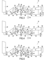
- FIGS. 2 to 5 show the turbojet 10 in other embodiments.
- elements corresponding to or identical to those of the first embodiment will receive the same reference sign and will not be described again.
- FIG. 1 illustrates in more detail the structure of the turbojet engine 10.
- the first reducer 40 is a differential reducer having an input wheel 44, in this case a planetary (also called planetary 44), rotationally integral with the turbine 80, here via a turbine shaft 82, and a first output wheel 48, in this case a crown (also called crown 48), integral in rotation with the fan 20, here via a fan shaft 22.
- the ratio R1 of the number of teeth of the first output wheel 48 to the number of teeth of the input wheel 44 is greater than 1 and is, in this embodiment, approximately 1.5.
- the transmission shaft 42 is a planet carrier for the first reducer 40 and, independently, is also a planet carrier for the second reducer 50.
- the second reducer 50 comprises one or more satellites 56 whose revolution is caused by the rotation of the satellite carrier 42.
- the second reducer 50 comprises, in addition to its input wheel 42, an output wheel 54, in this case a sun gear (also called sun gear 54), integral in rotation with the compressor 60, here via a compressor shaft 62.
- the sun gear 54 is engaged with the satellites 56.
- the satellites 56 can also be engaged with a crown 58, here fixed relative to the casing 30.
- the aforementioned ratio R1 is lower than the ratio R2.
- the first and second reducers 40, 50 are coaxial.
- the fan shaft 22, the compressor shaft 62 and the turbine shaft 82 may each, independently of one another, be supported by at least one bearing, or, in this embodiment, at least two bearings.
- the fan shaft 22 is supported relative to the casing 30 by a front fan bearing 21 and a rear fan bearing 23.
- the compressor shaft 62 is supported by a front compressor bearing 61 relative to the casing 30, and by a rear compressor bearing 63 relative to a structural member 72 downstream of the compressor, here a combustion chamber casing.
- the turbine shaft 82 is supported by a rear turbine bearing 83 relative to an exhaust casing 84, also known as a “turbine rear frame” (TRF).
- TRF turbine rear frame
- one of the bearings ensures axial locking of the shaft, for example in the form of a ball bearing, while the other of the bearings allows axial movement of the shaft, for example in the form of a ball bearing. rollers, to avoid hyperstaticism while controlling the axial position of the shaft.
- the front fan bearing 21 and the intershaft bearing 81 are roller bearings, while the rear fan and turbine bearings 23, 83, are ball bearings.
- the front compressor bearing 61 is a ball bearing, while the rear compressor bearing is a roller bearing.
- the first bearing 41 supporting the reduction shaft 42 may be a so-called “high radius” bearing, i.e. one whose radius is relatively close to that of the casing 30 on which it is fixed.
- said bearing 41 is arranged radially outside the compressor shaft 62, the turbine shaft 82 and the reduction shaft 42.
- the inventors estimate the mass gain between 5% and 15% for the turbojet 10 of the second embodiment, compared to a conventional dual-flow twin-body engine with single reducer.
- a power supply device 90 may be provided configured to provide additional power to that provided by the turbine 80 to drive the compressor 60.
- a power supply device may be compatible with the embodiments previously described.
- the power supply device may be of various nature.
- the power supply device 90 may be configured to provide power from a source separate from the turbine 80, said power therefore not being provided, directly or indirectly, instantaneously or in a deferred manner, by the turbine 80.
- the power supply device 90 comprises an electric motor 91 configured to rotate the compressor 60.
- the electric motor 91 may be engaged with the compressor shaft 62.
- the electrical energy of the electric motor 91 may come from an electric generator 92 configured to be driven by the turbine 80, or more precisely by the turbine shaft 82, in this embodiment.
- the power supply device 90 may comprise a connector 94 configured to be connected to an electrical power supply external to the turbojet engine and to provide the electric motor 91 with the necessary electrical energy, it being understood that the additional power to drive the compressor 60 despite the idle speed of the turbine 80 is useful mainly when the turbojet 10 operates in idle speed, on the ground as well as in flight, for example during the descent phase.
- the electrical energy intended to power the electric motor 91 may come from electricity storage means 96 electrically connected to the electric motor. If necessary, the electricity storage means 96 may be connected to the electric generator 92 or to the connector 94 illustrated in the third embodiment. Depending on the configuration, the electricity storage means 96 may act as a buffer to accumulate the energy produced by the electric generator 92 independently of its consumption by the electric motor 91.
- the electricity storage means 96 may comprise one or more batteries, or any other suitable storage means.
- the power supply device 90 comprises a variable mechanical or electromagnetic transmission coupled on the one hand to the shaft 62 of the compressor 60, on the other hand to the shaft 82 of the turbine 80. More precisely, the power supply device 90 comprises a first engagement element 98a integral in rotation with the compressor shaft 62, a second engagement element 98b integral in rotation with the turbine shaft 82.
- the first and second engagement elements 98a, 98b can be engaged with each other, in a variable manner (which includes the possibility of decoupling them), by means of a mechanical or electromagnetic connection 98c.
- the connection 98c can be a clutch, a differential system, an electromagnetic coupler or any other variable transmission of mechanical energy.
- the third, fourth and fifth embodiments have in common that the power supplied to the compressor 60 by the power supply device 90 is variable and can be controlled.
- a control unit 99 may be provided configured to control the power supply device 90.
- the control unit 99 may control the power supply device as a function of a rotational speed of the turbine 80 or of another parameter representative of the speed of the turbojet engine 10.
- it may be useful to activate the power supply device 90 when the turbine is rotating at a speed less than or equal to 95% of its maximum nominal rotational speed, and to deactivate the power supply device 90 for a rotational speed of the turbine greater than 95% of its maximum nominal rotational speed.
- the compressor 60 can be maintained in a stable rotational regime offering good operability, that is to say a capacity to maintain the stabilized and transient operating points of the turbomachine at a distance sufficiently far from the zones of aerodynamic instability.
- the power supply device 90 may be sized such that the maximum additional power provided by the power supply device may be greater than 1.5 Megawatts (MW), preferably greater than or equal to 1.8 MW, more preferably greater than or equal to 2.1 MW.
- MW Megawatts
- the power supply device 90 can, incidentally, be used as assistance in the acceleration of the turbojet 10, for example during start-up or during rapid transient maneuvers.
- the power supply device can be used in the context of a twin-spool, twin-flow turbojet engine, which comprises, in addition to the aforementioned compressor and turbine which form a high-pressure body, a low-pressure compressor or booster and a low-pressure turbine, positioned on either side of the high-pressure body and forming a low-pressure body.
- the low-pressure compressor is driven by the low-pressure turbine.
- the power supply device can be used to supply power to the high-pressure shaft in order to improve the operability of the high-pressure compressor by lowering its operating line, which is conventionally defined as the locus of points described in the compressor in a coordinate system [compression ratio; reduced mass flow], during all possible engine operating conditions, in particular between full throttle and idle.
- the supplied power can be taken from the low-pressure shaft, which improves the operability of the low-pressure compressor by lowering its operating line.
Landscapes
- Engineering & Computer Science (AREA)
- Mechanical Engineering (AREA)
- General Engineering & Computer Science (AREA)
- Chemical & Material Sciences (AREA)
- Combustion & Propulsion (AREA)
- Structures Of Non-Positive Displacement Pumps (AREA)
Claims (15)
- Doppelflussturboreaktor (10), umfassend eine Gebläse (20), ein Gehäuse (30), das stromabwärts des Gebläses (20) angeordnet ist und einen Primärstrom (12) von einem Sekundärstrom (14) trennt, wobei ein Verdichter (60), eine Brennkammer (70) und eine Turbine (80) in dem Primärstrom (12) angeordnet sind, wobei der Turboreaktor ein Differentialgetriebe umfasst, das an die Turbine (80), an den Verdichter (60) und an das Gebläse (20) gekoppelt ist, und eine Leistungsversorgungsvorrichtung (90), die dazu ausgestaltet ist, eine zusätzliche Leistung zu derjenigen, die durch die Turbine (80) geliefert wird, um den Verdichter (60) anzutreiben, zu liefern, wobei das Differentialgetriebe ein erstes Untersetzungsgetriebe (40) umfasst, das dazu ausgestaltet ist, das Drehzahlübertragungsverhältnis zwischen der Turbine (80) und dem Gebläse (20) zu modifizieren, dadurch gekennzeichnet, dass das Differentialgetriebe ein zweites Untersetzungsgetriebe (50) umfasst, das dazu ausgestaltet ist, das Drehzahlübertragungsverhältnis zwischen der Turbine (80) und dem Verdichter (60) zu modifizieren.
- Turboreaktor nach Anspruch 1, ferner umfassend eine Steuereinheit (99), die dazu ausgestaltet ist, die Leistungsversorgungsvorrichtung (90) in Abhängigkeit einer Drehzahl der Turbine (80) zu steuern.
- Turboreaktor nach Anspruch 1 oder 2, wobei die Leistungsversorgungsvorrichtung (90) einen Elektromotor (91), der dazu ausgestaltet ist, den Verdichter (60) drehend anzutreiben, und/oder einen Elektrogenerator (92), der dazu ausgestaltet ist, durch die Turbine (80) angetrieben zu werden, umfasst, und bevorzugt der Turboreaktor Elektrizitätsspeichermittel (96) umfasst, die elektrisch mit dem Elektromotor (91) oder dem Elektrogenerator (92) verbunden sind.
- Turboreaktor nach einem der Ansprüche 1 bis 3, wobei die Leistungsversorgungsvorrichtung (90) einen Verbinder (94) umfasst, der dazu ausgestaltet ist, mit einer externen elektrischen Speisung verbunden zu sein.
- Turboreaktor nach einem der Ansprüche 1 bis 4, wobei die Leistungsversorgungsvorrichtung (90) ein variables mechanisches Getriebe (98a, 98b, 98c) umfasst, das einerseits an die Welle des Verdichters (62), andererseits an die Welle der Turbine (82) gekoppelt ist.
- Turboreaktor nach einem der Ansprüche 1 bis 5, wobei die Leistungsversorgungsvorrichtung (90) ein elektromagnetisches Getriebe (98a, 98b, 98c) umfasst, das einerseits an die Welle des Verdichters (62), andererseits an die Welle der Turbine (82) gekoppelt ist.
- Turboreaktor nach einem der Ansprüche 1 bis 6, wobei die maximale zusätzliche Leistung, die durch die Leistungsversorgungsvorrichtung (90) geliefert wird, höher als 1,5 MW ist.
- Turboreaktor nach einem der Ansprüche 1 bis 7, wobei die Leistungsversorgungsvorrichtung (90) dazu ausgestaltet ist, deaktiviert zu sein, wenn die Drehzahl der Turbine (80) höher als 95 % der maximalen Nenndrehzahl der Turbine (80) ist.
- Turboreaktor nach einem der Ansprüche 1 bis 8, wobei der Turboreaktor (10) ein Turboreaktor mit einfachem Körper ist und das Verdünnungsverhältnis zwischen dem Sekundärstrom (14) und dem Primärstrom (12) höher als oder gleich 12 ist.
- Turboreaktor nach einem der Ansprüche 1 bis 9, wobei das erste Untersetzungsgetriebe (40) ein Differentialuntersetzungsgetriebe ist, das ein Eingangsrad (44), das drehfest mit der Turbine (80) ist, ein erstes Ausgangsrad (48), das drehfest mit dem Gebläse (20) ist, ein zweites Ausgangsrad (42), das drehfest mit einem Eingangsrad des zweiten Untersetzungsgetriebes (42) ist, aufweist, und das zweite Untersetzungsgetriebe (50) ein Umlaufuntersetzungsgetriebe ist, das ein Ausgangsrad (54), das drehfest mit dem Verdichter (60) ist, aufweist, und wobei bevorzugt das Verhältnis der Anzahl an Zähnen des ersten Ausgangsrads (48) des ersten Untersetzungsgetriebes (40) zu der Anzahl an Zähnen des Eingangsrads (44) des ersten Untersetzungsgetriebes (40) höher als 1 ist.
- Turboreaktor nach Anspruch 10, wobei das Verhältnis der Anzahl an Zähnen des Zahnkranzes (58) des zweiten Untersetzungsgetriebes (50) zu der Anzahl an Zähnen des Ausgangsrads (54) des zweiten Untersetzungsgetriebes (50) höher als 2 ist.
- Turboreaktor nach Anspruch 10 oder 11, wobei das Verhältnis der Anzahl an Zähnen des ersten Ausgangsrads (48) des ersten Untersetzungsgetriebes (40) zu der Anzahl an Zähnen des Eingangsrads (44) des ersten Untersetzungsgetriebes (40) kleiner in Bezug auf die Anzahl an Zähnen des Zahnkranzes (58) des zweiten Untersetzungsgetriebes (50) zu der Anzahl an Zähnen des Ausgangsrads (54) des zweiten Untersetzungsgetriebes (50) ist.
- Turboreaktor nach einem der Ansprüche 1 bis 12, wobei das zweite Untersetzungsgetriebe (50) ein Übersetzungsverhältnis höher als 3 aufweist und/oder wobei das Verdichtungsverhältnis des Gebläses (20) bei Reisegeschwindigkeit zwischen 1,3 und 1,45 umfasst.
- Turboreaktor nach einem der Ansprüche 1 bis 13, wobei das Verdichtungsverhältnis des Verdichters (60) höher als oder gleich 25 bei einer Drehzahl des Verdichters von 15500 Umdrehungen pro Minute ist.
- Turboreaktor nach einem der Ansprüche 1 bis 14, wobei das Gesamtdruckverhältnis höher als oder gleich 30 am Höhepunkt des Steigflugs ist.
Applications Claiming Priority (3)
| Application Number | Priority Date | Filing Date | Title |
|---|---|---|---|
| FR1858588A FR3086340B1 (fr) | 2018-09-21 | 2018-09-21 | Turboreacteur comprenant un dispositif d'apport de puissance |
| FR1858586A FR3086342B1 (fr) | 2018-09-21 | 2018-09-21 | Turboreacteur a reducteur |
| PCT/FR2019/052211 WO2020058652A1 (fr) | 2018-09-21 | 2019-09-20 | Turboréacteur comprenant un dispositif d'apport de puissance |
Publications (2)
| Publication Number | Publication Date |
|---|---|
| EP3853466A1 EP3853466A1 (de) | 2021-07-28 |
| EP3853466B1 true EP3853466B1 (de) | 2025-03-05 |
Family
ID=68296515
Family Applications (1)
| Application Number | Title | Priority Date | Filing Date |
|---|---|---|---|
| EP19790680.3A Active EP3853466B1 (de) | 2018-09-21 | 2019-09-20 | Turboreaktor mit einer leistungs-versorgungsvorrichtung |
Country Status (4)
| Country | Link |
|---|---|
| US (1) | US11891967B2 (de) |
| EP (1) | EP3853466B1 (de) |
| CN (1) | CN112739901B (de) |
| WO (1) | WO2020058652A1 (de) |
Families Citing this family (10)
| Publication number | Priority date | Publication date | Assignee | Title |
|---|---|---|---|---|
| US12480450B2 (en) | 2021-06-28 | 2025-11-25 | Rtx Corporation | Hybrid electric multiple shaft core |
| FR3129137B1 (fr) * | 2021-11-12 | 2023-10-06 | Safran Aircraft Engines | Pompe hydraulique réversible pour le calage de pas d’hélice, système hydraulique, turbopropulseur et aéronef associés |
| EP4282763B1 (de) * | 2022-05-26 | 2025-03-05 | RTX Corporation | Selektive leistungsverteilung für ein flugzeugantriebssystem |
| US12292005B2 (en) * | 2022-08-12 | 2025-05-06 | Rtx Corporation | Aircraft propulsion system geartrain |
| US12135076B1 (en) | 2023-09-29 | 2024-11-05 | Rtx Corporation | Fluid device(s) for supporting rotating structure(s) of a turbine engine |
| US12331683B2 (en) | 2023-09-29 | 2025-06-17 | Rtx Corporation | Bearing arrangement for turbine engine geartrain |
| US12188551B1 (en) | 2023-09-29 | 2025-01-07 | Rtx Corporation | Reduced clearance interface between a fluid device and a rotating structure for a geartrain |
| US12292107B2 (en) | 2023-09-29 | 2025-05-06 | Rtx Corporation | Fluid damper for turbine engine geartrain assembly |
| FR3155032A1 (fr) | 2023-11-07 | 2025-05-09 | Safran Aircraft Engines | Turboreacteur hybride comprenant un variateur de vitesse pour deux machines electriques |
| US12415609B2 (en) | 2024-02-12 | 2025-09-16 | Pratt & Whitney Canada Corp. | Hybrid aircraft power plant |
Family Cites Families (28)
| Publication number | Priority date | Publication date | Assignee | Title |
|---|---|---|---|---|
| FR2360758A1 (fr) * | 1976-08-02 | 1978-03-03 | Gen Electric | Moteur a turbine a gaz d'avion |
| US6895741B2 (en) * | 2003-06-23 | 2005-05-24 | Pratt & Whitney Canada Corp. | Differential geared turbine engine with torque modulation capability |
| US7882693B2 (en) | 2006-11-29 | 2011-02-08 | General Electric Company | Turbofan engine assembly and method of assembling same |
| US7791235B2 (en) * | 2006-12-22 | 2010-09-07 | General Electric Company | Variable magnetic coupling of rotating machinery |
| US20100126178A1 (en) * | 2008-10-08 | 2010-05-27 | Searete Llc, A Limited Liability Corporation Of The State Of Delaware | Hybrid propulsive engine including at least one independently rotatable turbine stator |
| US8181441B2 (en) * | 2009-02-27 | 2012-05-22 | United Technologies Corporation | Controlled fan stream flow bypass |
| FR2972765B1 (fr) * | 2011-03-17 | 2013-04-05 | Messier Dowty | Procede d'optimisation de vitesse de soufflante de turboreacteur double-corps et architecture de mise en oeuvre. |
| US10018119B2 (en) | 2012-04-02 | 2018-07-10 | United Technologies Corporation | Geared architecture with inducer for gas turbine engine |
| US8956108B2 (en) * | 2012-05-11 | 2015-02-17 | Pratt & Whitney Canada Corp | Geared fan assembly |
| US20140090388A1 (en) * | 2012-09-28 | 2014-04-03 | United Technologies Corporation | Off-take power ratio |
| US10036316B2 (en) * | 2012-10-02 | 2018-07-31 | United Technologies Corporation | Geared turbofan engine with high compressor exit temperature |
| US20140205438A1 (en) * | 2013-01-21 | 2014-07-24 | United Technologies Corporation | Relationship between fan and primary exhaust stream velocities in a geared gas turbine engine |
| US10094295B2 (en) | 2013-01-30 | 2018-10-09 | Pratt & Whitney Canada Corp. | Gas turbine engine with transmission |
| EP3039276B1 (de) | 2013-08-29 | 2019-12-25 | United Technologies Corporation | Drei-wellen-getriebeturbolüfter mit niederdruckverdichterantriebssystem und mechanischer steuerung |
| GB201406386D0 (en) * | 2014-04-09 | 2014-05-21 | Rolls Royce Plc | Gas turbine engine |
| GB201412189D0 (en) * | 2014-07-09 | 2014-08-20 | Rolls Royce Plc | A nozzle arrangement for a gas turbine engine |
| US10119460B2 (en) * | 2014-09-18 | 2018-11-06 | General Electric Company | Integrated turboshaft engine |
| BE1024024B1 (fr) | 2014-10-09 | 2017-10-30 | Safran Aero Boosters S.A. | Compresseur de turbomachine axiale avec rotor contrarotatif |
| DE102014222870A1 (de) | 2014-11-10 | 2016-05-12 | MTU Aero Engines AG | Gasturbine |
| FR3034140B1 (fr) * | 2015-03-26 | 2018-09-07 | Safran Aircraft Engines | Turbomachine d’aeronef a reducteur planetaire ou epicycloidal |
| WO2016166487A1 (fr) * | 2015-04-17 | 2016-10-20 | Safran Aircraft Engines | Turbomoteur a doublet d'helices contrarotatives dispose en amont du generateur de gaz |
| FR3043714B1 (fr) * | 2015-11-16 | 2017-12-22 | Snecma | Partie avant de turbomachine d'aeronef comprenant une soufflante unique entrainee par un reducteur, ainsi que des aubes directrices de sortie structurales agencees en partie en amont d'un bec de separation |
| US10669947B2 (en) * | 2016-07-11 | 2020-06-02 | Raytheon Technologies Corporation | Geared gas turbine engine |
| US10487748B2 (en) * | 2016-12-05 | 2019-11-26 | United Technologies Corporation | Cooling air for gas turbine engine with supercharged low pressure compressor |
| US10953995B2 (en) * | 2017-06-30 | 2021-03-23 | General Electric Company | Propulsion system for an aircraft |
| US11008883B2 (en) * | 2017-09-20 | 2021-05-18 | General Electric Company | Turbomachine with a gearbox and integrated electric machine assembly |
| US11149649B2 (en) * | 2018-08-17 | 2021-10-19 | Raytheon Technologies Corporation | Hybrid gas turbine engine system powered warm-up |
| FR3086348B1 (fr) * | 2018-09-21 | 2020-12-04 | Safran Aircraft Engines | Turboreacteur a reducteur |
-
2019
- 2019-09-20 EP EP19790680.3A patent/EP3853466B1/de active Active
- 2019-09-20 US US17/277,801 patent/US11891967B2/en active Active
- 2019-09-20 CN CN201980061427.3A patent/CN112739901B/zh active Active
- 2019-09-20 WO PCT/FR2019/052211 patent/WO2020058652A1/fr not_active Ceased
Also Published As
| Publication number | Publication date |
|---|---|
| US11891967B2 (en) | 2024-02-06 |
| CN112739901A (zh) | 2021-04-30 |
| EP3853466A1 (de) | 2021-07-28 |
| US20210317800A1 (en) | 2021-10-14 |
| CN112739901B (zh) | 2024-07-30 |
| WO2020058652A1 (fr) | 2020-03-26 |
Similar Documents
| Publication | Publication Date | Title |
|---|---|---|
| EP3853466B1 (de) | Turboreaktor mit einer leistungs-versorgungsvorrichtung | |
| EP3853456B1 (de) | Turboluftstrahltriebwerk mit drehzahlreduktionsmechanismus | |
| EP3464855B1 (de) | Flugzeugturbinentriebwerk mit epizyklischem untersetzungsgetriebe mit variablem übersetzungsverhältnis | |
| WO2011033204A1 (fr) | Turbomachine a helices non carenees contrarotatives | |
| EP4073366B1 (de) | Aeronautisches antriebssystem mit niedriger leckrate und verbesserter antriebseffizienz | |
| WO2021116621A1 (fr) | Système propulsif aéronautique à rendement propulsif amélioré | |
| EP4073371B1 (de) | Aeronautisches antriebssystem mit geringer leckflussrate und verbesserter antriebssystemseffizienz | |
| EP3580432B1 (de) | Strahlturbine mit einer architektur aus lagern, die zur stützung einer niederdruckwelle optimiert sind | |
| EP4073356B1 (de) | Turbomaschine für ein flugzeug, die eine gegenläufige turbine aufweist | |
| FR3086340A1 (fr) | Turboreacteur comprenant un dispositif d'apport de puissance | |
| FR3086342A1 (fr) | Turboreacteur a reducteur | |
| FR3116511A1 (fr) | Ensemble propulsif comprenant deux hélices contrarotatives | |
| FR3104644A1 (fr) | Système propulsif aéronautique à rendement propulsif amélioré | |
| EP4229286B1 (de) | Aeronautisches antriebssystem mit verbesserter antriebseffizienz | |
| EP4127437B1 (de) | Flugzeugturbomaschine | |
| WO2025078765A1 (fr) | Arbre de compresseur pour une turbomachine d'aéronef | |
| WO2024246458A1 (fr) | Système propulsif aéronautique à rendement propulsif amélioré | |
| FR3145381A1 (fr) | Système propulsif aéronautique comprenant une section de soufflante optimisée | |
| WO2024100355A1 (fr) | Système propulsif aéronautique à rendement propulsif amélioré | |
| EP4720469A1 (de) | Aeronautisches antriebssystem mit verbesserter antriebseffizienz | |
| WO2025141263A1 (fr) | Mecanisme de reduction pour systeme propulsif aeronautique | |
| EP4665959A1 (de) | Optimierung des verhaltens des lüfters in einem aeronautischen antriebssystem | |
| FR3107313A1 (fr) | Arbre d’entrée flexible tronconique |
Legal Events
| Date | Code | Title | Description |
|---|---|---|---|
| STAA | Information on the status of an ep patent application or granted ep patent |
Free format text: STATUS: UNKNOWN |
|
| STAA | Information on the status of an ep patent application or granted ep patent |
Free format text: STATUS: THE INTERNATIONAL PUBLICATION HAS BEEN MADE |
|
| PUAI | Public reference made under article 153(3) epc to a published international application that has entered the european phase |
Free format text: ORIGINAL CODE: 0009012 |
|
| STAA | Information on the status of an ep patent application or granted ep patent |
Free format text: STATUS: REQUEST FOR EXAMINATION WAS MADE |
|
| 17P | Request for examination filed |
Effective date: 20210329 |
|
| AK | Designated contracting states |
Kind code of ref document: A1 Designated state(s): AL AT BE BG CH CY CZ DE DK EE ES FI FR GB GR HR HU IE IS IT LI LT LU LV MC MK MT NL NO PL PT RO RS SE SI SK SM TR |
|
| DAV | Request for validation of the european patent (deleted) | ||
| DAX | Request for extension of the european patent (deleted) | ||
| STAA | Information on the status of an ep patent application or granted ep patent |
Free format text: STATUS: EXAMINATION IS IN PROGRESS |
|
| 17Q | First examination report despatched |
Effective date: 20230913 |
|
| REG | Reference to a national code |
Ref country code: DE Ref legal event code: R079 Free format text: PREVIOUS MAIN CLASS: F02K0003000000 Ipc: F02C0007360000 Ref country code: DE Ref legal event code: R079 Ref document number: 602019066922 Country of ref document: DE Free format text: PREVIOUS MAIN CLASS: F02K0003000000 Ipc: F02C0007360000 |
|
| GRAP | Despatch of communication of intention to grant a patent |
Free format text: ORIGINAL CODE: EPIDOSNIGR1 |
|
| STAA | Information on the status of an ep patent application or granted ep patent |
Free format text: STATUS: GRANT OF PATENT IS INTENDED |
|
| RIC1 | Information provided on ipc code assigned before grant |
Ipc: F02C 7/36 20060101AFI20240927BHEP |
|
| INTG | Intention to grant announced |
Effective date: 20241015 |
|
| GRAS | Grant fee paid |
Free format text: ORIGINAL CODE: EPIDOSNIGR3 |
|
| GRAA | (expected) grant |
Free format text: ORIGINAL CODE: 0009210 |
|
| STAA | Information on the status of an ep patent application or granted ep patent |
Free format text: STATUS: THE PATENT HAS BEEN GRANTED |
|
| AK | Designated contracting states |
Kind code of ref document: B1 Designated state(s): AL AT BE BG CH CY CZ DE DK EE ES FI FR GB GR HR HU IE IS IT LI LT LU LV MC MK MT NL NO PL PT RO RS SE SI SK SM TR |
|
| REG | Reference to a national code |
Ref country code: GB Ref legal event code: FG4D Free format text: NOT ENGLISH |
|
| REG | Reference to a national code |
Ref country code: CH Ref legal event code: EP |
|
| REG | Reference to a national code |
Ref country code: DE Ref legal event code: R096 Ref document number: 602019066922 Country of ref document: DE |
|
| REG | Reference to a national code |
Ref country code: IE Ref legal event code: FG4D Free format text: LANGUAGE OF EP DOCUMENT: FRENCH |
|
| PG25 | Lapsed in a contracting state [announced via postgrant information from national office to epo] |
Ref country code: RS Free format text: LAPSE BECAUSE OF FAILURE TO SUBMIT A TRANSLATION OF THE DESCRIPTION OR TO PAY THE FEE WITHIN THE PRESCRIBED TIME-LIMIT Effective date: 20250605 |
|
| PG25 | Lapsed in a contracting state [announced via postgrant information from national office to epo] |
Ref country code: FI Free format text: LAPSE BECAUSE OF FAILURE TO SUBMIT A TRANSLATION OF THE DESCRIPTION OR TO PAY THE FEE WITHIN THE PRESCRIBED TIME-LIMIT Effective date: 20250305 |
|
| REG | Reference to a national code |
Ref country code: NL Ref legal event code: MP Effective date: 20250305 |
|
| PG25 | Lapsed in a contracting state [announced via postgrant information from national office to epo] |
Ref country code: ES Free format text: LAPSE BECAUSE OF FAILURE TO SUBMIT A TRANSLATION OF THE DESCRIPTION OR TO PAY THE FEE WITHIN THE PRESCRIBED TIME-LIMIT Effective date: 20250305 |
|
| REG | Reference to a national code |
Ref country code: LT Ref legal event code: MG9D |
|
| PG25 | Lapsed in a contracting state [announced via postgrant information from national office to epo] |
Ref country code: NO Free format text: LAPSE BECAUSE OF FAILURE TO SUBMIT A TRANSLATION OF THE DESCRIPTION OR TO PAY THE FEE WITHIN THE PRESCRIBED TIME-LIMIT Effective date: 20250605 |
|
| PG25 | Lapsed in a contracting state [announced via postgrant information from national office to epo] |
Ref country code: HR Free format text: LAPSE BECAUSE OF FAILURE TO SUBMIT A TRANSLATION OF THE DESCRIPTION OR TO PAY THE FEE WITHIN THE PRESCRIBED TIME-LIMIT Effective date: 20250305 |
|
| PG25 | Lapsed in a contracting state [announced via postgrant information from national office to epo] |
Ref country code: LV Free format text: LAPSE BECAUSE OF FAILURE TO SUBMIT A TRANSLATION OF THE DESCRIPTION OR TO PAY THE FEE WITHIN THE PRESCRIBED TIME-LIMIT Effective date: 20250305 |
|
| PG25 | Lapsed in a contracting state [announced via postgrant information from national office to epo] |
Ref country code: BG Free format text: LAPSE BECAUSE OF FAILURE TO SUBMIT A TRANSLATION OF THE DESCRIPTION OR TO PAY THE FEE WITHIN THE PRESCRIBED TIME-LIMIT Effective date: 20250305 Ref country code: GR Free format text: LAPSE BECAUSE OF FAILURE TO SUBMIT A TRANSLATION OF THE DESCRIPTION OR TO PAY THE FEE WITHIN THE PRESCRIBED TIME-LIMIT Effective date: 20250606 |
|
| REG | Reference to a national code |
Ref country code: AT Ref legal event code: MK05 Ref document number: 1773116 Country of ref document: AT Kind code of ref document: T Effective date: 20250305 |
|
| PG25 | Lapsed in a contracting state [announced via postgrant information from national office to epo] |
Ref country code: NL Free format text: LAPSE BECAUSE OF FAILURE TO SUBMIT A TRANSLATION OF THE DESCRIPTION OR TO PAY THE FEE WITHIN THE PRESCRIBED TIME-LIMIT Effective date: 20250305 |
|
| PG25 | Lapsed in a contracting state [announced via postgrant information from national office to epo] |
Ref country code: SE Free format text: LAPSE BECAUSE OF FAILURE TO SUBMIT A TRANSLATION OF THE DESCRIPTION OR TO PAY THE FEE WITHIN THE PRESCRIBED TIME-LIMIT Effective date: 20250305 |
|
| PG25 | Lapsed in a contracting state [announced via postgrant information from national office to epo] |
Ref country code: SM Free format text: LAPSE BECAUSE OF FAILURE TO SUBMIT A TRANSLATION OF THE DESCRIPTION OR TO PAY THE FEE WITHIN THE PRESCRIBED TIME-LIMIT Effective date: 20250305 |
|
| PG25 | Lapsed in a contracting state [announced via postgrant information from national office to epo] |
Ref country code: PT Free format text: LAPSE BECAUSE OF FAILURE TO SUBMIT A TRANSLATION OF THE DESCRIPTION OR TO PAY THE FEE WITHIN THE PRESCRIBED TIME-LIMIT Effective date: 20250707 |
|
| PGFP | Annual fee paid to national office [announced via postgrant information from national office to epo] |
Ref country code: DE Payment date: 20250919 Year of fee payment: 7 |
|
| PG25 | Lapsed in a contracting state [announced via postgrant information from national office to epo] |
Ref country code: IT Free format text: LAPSE BECAUSE OF FAILURE TO SUBMIT A TRANSLATION OF THE DESCRIPTION OR TO PAY THE FEE WITHIN THE PRESCRIBED TIME-LIMIT Effective date: 20250305 Ref country code: PL Free format text: LAPSE BECAUSE OF FAILURE TO SUBMIT A TRANSLATION OF THE DESCRIPTION OR TO PAY THE FEE WITHIN THE PRESCRIBED TIME-LIMIT Effective date: 20250305 |
|
| PGFP | Annual fee paid to national office [announced via postgrant information from national office to epo] |
Ref country code: GB Payment date: 20250923 Year of fee payment: 7 |
|
| PG25 | Lapsed in a contracting state [announced via postgrant information from national office to epo] |
Ref country code: AT Free format text: LAPSE BECAUSE OF FAILURE TO SUBMIT A TRANSLATION OF THE DESCRIPTION OR TO PAY THE FEE WITHIN THE PRESCRIBED TIME-LIMIT Effective date: 20250305 |
|
| PGFP | Annual fee paid to national office [announced via postgrant information from national office to epo] |
Ref country code: FR Payment date: 20250923 Year of fee payment: 7 |
|
| PG25 | Lapsed in a contracting state [announced via postgrant information from national office to epo] |
Ref country code: CZ Free format text: LAPSE BECAUSE OF FAILURE TO SUBMIT A TRANSLATION OF THE DESCRIPTION OR TO PAY THE FEE WITHIN THE PRESCRIBED TIME-LIMIT Effective date: 20250305 Ref country code: EE Free format text: LAPSE BECAUSE OF FAILURE TO SUBMIT A TRANSLATION OF THE DESCRIPTION OR TO PAY THE FEE WITHIN THE PRESCRIBED TIME-LIMIT Effective date: 20250305 |
|
| PG25 | Lapsed in a contracting state [announced via postgrant information from national office to epo] |
Ref country code: RO Free format text: LAPSE BECAUSE OF FAILURE TO SUBMIT A TRANSLATION OF THE DESCRIPTION OR TO PAY THE FEE WITHIN THE PRESCRIBED TIME-LIMIT Effective date: 20250305 |
|
| PG25 | Lapsed in a contracting state [announced via postgrant information from national office to epo] |
Ref country code: SK Free format text: LAPSE BECAUSE OF FAILURE TO SUBMIT A TRANSLATION OF THE DESCRIPTION OR TO PAY THE FEE WITHIN THE PRESCRIBED TIME-LIMIT Effective date: 20250305 |
|
| PG25 | Lapsed in a contracting state [announced via postgrant information from national office to epo] |
Ref country code: IS Free format text: LAPSE BECAUSE OF FAILURE TO SUBMIT A TRANSLATION OF THE DESCRIPTION OR TO PAY THE FEE WITHIN THE PRESCRIBED TIME-LIMIT Effective date: 20250705 |
|
| REG | Reference to a national code |
Ref country code: DE Ref legal event code: R097 Ref document number: 602019066922 Country of ref document: DE |
|
| PLBE | No opposition filed within time limit |
Free format text: ORIGINAL CODE: 0009261 |
|
| STAA | Information on the status of an ep patent application or granted ep patent |
Free format text: STATUS: NO OPPOSITION FILED WITHIN TIME LIMIT |
|
| PG25 | Lapsed in a contracting state [announced via postgrant information from national office to epo] |
Ref country code: DK Free format text: LAPSE BECAUSE OF FAILURE TO SUBMIT A TRANSLATION OF THE DESCRIPTION OR TO PAY THE FEE WITHIN THE PRESCRIBED TIME-LIMIT Effective date: 20250305 |
|
| REG | Reference to a national code |
Ref country code: CH Ref legal event code: L10 Free format text: ST27 STATUS EVENT CODE: U-0-0-L10-L00 (AS PROVIDED BY THE NATIONAL OFFICE) Effective date: 20260114 |
|
| 26N | No opposition filed |
Effective date: 20251208 |