EP3853438B1 - Auflösbares gewindeband und stopfen für bohrlöcher - Google Patents
Auflösbares gewindeband und stopfen für bohrlöcher Download PDFInfo
- Publication number
- EP3853438B1 EP3853438B1 EP19863493.3A EP19863493A EP3853438B1 EP 3853438 B1 EP3853438 B1 EP 3853438B1 EP 19863493 A EP19863493 A EP 19863493A EP 3853438 B1 EP3853438 B1 EP 3853438B1
- Authority
- EP
- European Patent Office
- Prior art keywords
- degradable
- plug
- tape
- well
- hours
- Prior art date
- Legal status (The legal status is an assumption and is not a legal conclusion. Google has not performed a legal analysis and makes no representation as to the accuracy of the status listed.)
- Active
Links
- 238000000034 method Methods 0.000 claims description 43
- 239000012530 fluid Substances 0.000 claims description 31
- 238000012360 testing method Methods 0.000 claims description 29
- 230000000593 degrading effect Effects 0.000 claims description 19
- 230000015556 catabolic process Effects 0.000 claims description 18
- 238000006731 degradation reaction Methods 0.000 claims description 18
- 229930195733 hydrocarbon Natural products 0.000 claims description 13
- 150000002430 hydrocarbons Chemical class 0.000 claims description 13
- 239000004215 Carbon black (E152) Substances 0.000 claims description 12
- 230000000903 blocking effect Effects 0.000 claims description 8
- 239000007787 solid Substances 0.000 claims description 7
- 230000000694 effects Effects 0.000 claims description 6
- 239000007864 aqueous solution Substances 0.000 claims description 4
- 239000010779 crude oil Substances 0.000 claims description 2
- 239000000463 material Substances 0.000 description 11
- 239000004809 Teflon Substances 0.000 description 10
- 238000004519 manufacturing process Methods 0.000 description 10
- 239000004568 cement Substances 0.000 description 9
- 229910052751 metal Inorganic materials 0.000 description 7
- 239000002184 metal Substances 0.000 description 7
- 230000008569 process Effects 0.000 description 7
- 238000004090 dissolution Methods 0.000 description 6
- 229920000642 polymer Polymers 0.000 description 6
- 229920000459 Nitrile rubber Polymers 0.000 description 5
- 238000000576 coating method Methods 0.000 description 5
- 239000013505 freshwater Substances 0.000 description 5
- 239000004626 polylactic acid Substances 0.000 description 5
- YMWUJEATGCHHMB-UHFFFAOYSA-N Dichloromethane Chemical compound ClCCl YMWUJEATGCHHMB-UHFFFAOYSA-N 0.000 description 4
- ZMXDDKWLCZADIW-UHFFFAOYSA-N N,N-Dimethylformamide Chemical compound CN(C)C=O ZMXDDKWLCZADIW-UHFFFAOYSA-N 0.000 description 4
- 239000004372 Polyvinyl alcohol Substances 0.000 description 4
- 239000002253 acid Substances 0.000 description 4
- 239000011248 coating agent Substances 0.000 description 4
- 229920006168 hydrated nitrile rubber Polymers 0.000 description 4
- 239000001866 hydroxypropyl methyl cellulose Substances 0.000 description 4
- 229920003088 hydroxypropyl methyl cellulose Polymers 0.000 description 4
- 235000010979 hydroxypropyl methyl cellulose Nutrition 0.000 description 4
- UFVKGYZPFZQRLF-UHFFFAOYSA-N hydroxypropyl methyl cellulose Chemical compound OC1C(O)C(OC)OC(CO)C1OC1C(O)C(O)C(OC2C(C(O)C(OC3C(C(O)C(O)C(CO)O3)O)C(CO)O2)O)C(CO)O1 UFVKGYZPFZQRLF-UHFFFAOYSA-N 0.000 description 4
- 229920000747 poly(lactic acid) Polymers 0.000 description 4
- 229920002451 polyvinyl alcohol Polymers 0.000 description 4
- 229920005989 resin Polymers 0.000 description 4
- 239000011347 resin Substances 0.000 description 4
- XLYOFNOQVPJJNP-UHFFFAOYSA-N water Substances O XLYOFNOQVPJJNP-UHFFFAOYSA-N 0.000 description 4
- 229920002134 Carboxymethyl cellulose Polymers 0.000 description 3
- OKKJLVBELUTLKV-UHFFFAOYSA-N Methanol Chemical compound OC OKKJLVBELUTLKV-UHFFFAOYSA-N 0.000 description 3
- FXHOOIRPVKKKFG-UHFFFAOYSA-N N,N-Dimethylacetamide Chemical compound CN(C)C(C)=O FXHOOIRPVKKKFG-UHFFFAOYSA-N 0.000 description 3
- 230000002378 acidificating effect Effects 0.000 description 3
- 239000002131 composite material Substances 0.000 description 3
- 239000005038 ethylene vinyl acetate Substances 0.000 description 3
- 239000011159 matrix material Substances 0.000 description 3
- 229920001200 poly(ethylene-vinyl acetate) Polymers 0.000 description 3
- 239000004810 polytetrafluoroethylene Substances 0.000 description 3
- 229920001343 polytetrafluoroethylene Polymers 0.000 description 3
- 238000005086 pumping Methods 0.000 description 3
- 239000000565 sealant Substances 0.000 description 3
- 230000000638 stimulation Effects 0.000 description 3
- CSCPPACGZOOCGX-UHFFFAOYSA-N Acetone Chemical compound CC(C)=O CSCPPACGZOOCGX-UHFFFAOYSA-N 0.000 description 2
- HEDRZPFGACZZDS-UHFFFAOYSA-N Chloroform Chemical compound ClC(Cl)Cl HEDRZPFGACZZDS-UHFFFAOYSA-N 0.000 description 2
- XEEYBQQBJWHFJM-UHFFFAOYSA-N Iron Chemical compound [Fe] XEEYBQQBJWHFJM-UHFFFAOYSA-N 0.000 description 2
- FYYHWMGAXLPEAU-UHFFFAOYSA-N Magnesium Chemical compound [Mg] FYYHWMGAXLPEAU-UHFFFAOYSA-N 0.000 description 2
- PXHVJJICTQNCMI-UHFFFAOYSA-N Nickel Chemical compound [Ni] PXHVJJICTQNCMI-UHFFFAOYSA-N 0.000 description 2
- 229910045601 alloy Inorganic materials 0.000 description 2
- 239000000956 alloy Substances 0.000 description 2
- -1 but not limited to Chemical class 0.000 description 2
- DQXBYHZEEUGOBF-UHFFFAOYSA-N but-3-enoic acid;ethene Chemical compound C=C.OC(=O)CC=C DQXBYHZEEUGOBF-UHFFFAOYSA-N 0.000 description 2
- 239000001768 carboxy methyl cellulose Substances 0.000 description 2
- 235000010948 carboxy methyl cellulose Nutrition 0.000 description 2
- 239000008112 carboxymethyl-cellulose Substances 0.000 description 2
- 239000003518 caustics Substances 0.000 description 2
- 229920002678 cellulose Polymers 0.000 description 2
- 239000001913 cellulose Substances 0.000 description 2
- 230000008859 change Effects 0.000 description 2
- 230000006378 damage Effects 0.000 description 2
- 229920006237 degradable polymer Polymers 0.000 description 2
- HDERJYVLTPVNRI-UHFFFAOYSA-N ethene;ethenyl acetate Chemical compound C=C.CC(=O)OC=C HDERJYVLTPVNRI-UHFFFAOYSA-N 0.000 description 2
- 229920001038 ethylene copolymer Polymers 0.000 description 2
- 239000007788 liquid Substances 0.000 description 2
- 229910052749 magnesium Inorganic materials 0.000 description 2
- 239000011777 magnesium Substances 0.000 description 2
- 238000005259 measurement Methods 0.000 description 2
- 150000002739 metals Chemical class 0.000 description 2
- VNWKTOKETHGBQD-UHFFFAOYSA-N methane Chemical compound C VNWKTOKETHGBQD-UHFFFAOYSA-N 0.000 description 2
- 239000000203 mixture Substances 0.000 description 2
- 239000003921 oil Substances 0.000 description 2
- 239000002245 particle Substances 0.000 description 2
- 239000004814 polyurethane Substances 0.000 description 2
- 238000011282 treatment Methods 0.000 description 2
- BYEAHWXPCBROCE-UHFFFAOYSA-N 1,1,1,3,3,3-hexafluoropropan-2-ol Chemical compound FC(F)(F)C(O)C(F)(F)F BYEAHWXPCBROCE-UHFFFAOYSA-N 0.000 description 1
- XQMVBICWFFHDNN-UHFFFAOYSA-N 5-amino-4-chloro-2-phenylpyridazin-3-one;(2-ethoxy-3,3-dimethyl-2h-1-benzofuran-5-yl) methanesulfonate Chemical compound O=C1C(Cl)=C(N)C=NN1C1=CC=CC=C1.C1=C(OS(C)(=O)=O)C=C2C(C)(C)C(OCC)OC2=C1 XQMVBICWFFHDNN-UHFFFAOYSA-N 0.000 description 1
- OYPRJOBELJOOCE-UHFFFAOYSA-N Calcium Chemical compound [Ca] OYPRJOBELJOOCE-UHFFFAOYSA-N 0.000 description 1
- VYZAMTAEIAYCRO-UHFFFAOYSA-N Chromium Chemical compound [Cr] VYZAMTAEIAYCRO-UHFFFAOYSA-N 0.000 description 1
- LYCAIKOWRPUZTN-UHFFFAOYSA-N Ethylene glycol Chemical compound OCCO LYCAIKOWRPUZTN-UHFFFAOYSA-N 0.000 description 1
- DGAQECJNVWCQMB-PUAWFVPOSA-M Ilexoside XXIX Chemical compound C[C@@H]1CC[C@@]2(CC[C@@]3(C(=CC[C@H]4[C@]3(CC[C@@H]5[C@@]4(CC[C@@H](C5(C)C)OS(=O)(=O)[O-])C)C)[C@@H]2[C@]1(C)O)C)C(=O)O[C@H]6[C@@H]([C@H]([C@@H]([C@H](O6)CO)O)O)O.[Na+] DGAQECJNVWCQMB-PUAWFVPOSA-M 0.000 description 1
- 229910000861 Mg alloy Inorganic materials 0.000 description 1
- MHABMANUFPZXEB-UHFFFAOYSA-N O-demethyl-aloesaponarin I Natural products O=C1C2=CC=CC(O)=C2C(=O)C2=C1C=C(O)C(C(O)=O)=C2C MHABMANUFPZXEB-UHFFFAOYSA-N 0.000 description 1
- ATJFFYVFTNAWJD-UHFFFAOYSA-N Tin Chemical compound [Sn] ATJFFYVFTNAWJD-UHFFFAOYSA-N 0.000 description 1
- HCHKCACWOHOZIP-UHFFFAOYSA-N Zinc Chemical compound [Zn] HCHKCACWOHOZIP-UHFFFAOYSA-N 0.000 description 1
- 150000007513 acids Chemical class 0.000 description 1
- 239000008186 active pharmaceutical agent Substances 0.000 description 1
- 239000000654 additive Substances 0.000 description 1
- 230000000996 additive effect Effects 0.000 description 1
- 229910052782 aluminium Inorganic materials 0.000 description 1
- XAGFODPZIPBFFR-UHFFFAOYSA-N aluminium Chemical compound [Al] XAGFODPZIPBFFR-UHFFFAOYSA-N 0.000 description 1
- 230000003466 anti-cipated effect Effects 0.000 description 1
- 229910052788 barium Inorganic materials 0.000 description 1
- DSAJWYNOEDNPEQ-UHFFFAOYSA-N barium atom Chemical compound [Ba] DSAJWYNOEDNPEQ-UHFFFAOYSA-N 0.000 description 1
- 230000008901 benefit Effects 0.000 description 1
- 230000015572 biosynthetic process Effects 0.000 description 1
- 239000012267 brine Substances 0.000 description 1
- 229910052791 calcium Inorganic materials 0.000 description 1
- 239000011575 calcium Substances 0.000 description 1
- 238000002144 chemical decomposition reaction Methods 0.000 description 1
- 229910052804 chromium Inorganic materials 0.000 description 1
- 239000011651 chromium Substances 0.000 description 1
- 229910017052 cobalt Inorganic materials 0.000 description 1
- 239000010941 cobalt Substances 0.000 description 1
- GUTLYIVDDKVIGB-UHFFFAOYSA-N cobalt atom Chemical compound [Co] GUTLYIVDDKVIGB-UHFFFAOYSA-N 0.000 description 1
- 238000004891 communication Methods 0.000 description 1
- 238000004132 cross linking Methods 0.000 description 1
- 230000001934 delay Effects 0.000 description 1
- 238000005553 drilling Methods 0.000 description 1
- 230000009977 dual effect Effects 0.000 description 1
- 229920001971 elastomer Polymers 0.000 description 1
- 239000000839 emulsion Substances 0.000 description 1
- 239000003822 epoxy resin Substances 0.000 description 1
- 239000000835 fiber Substances 0.000 description 1
- 239000011152 fibreglass Substances 0.000 description 1
- 210000003108 foot joint Anatomy 0.000 description 1
- 238000005755 formation reaction Methods 0.000 description 1
- 230000006872 improvement Effects 0.000 description 1
- 230000002401 inhibitory effect Effects 0.000 description 1
- 230000000977 initiatory effect Effects 0.000 description 1
- 238000002347 injection Methods 0.000 description 1
- 239000007924 injection Substances 0.000 description 1
- 229910052742 iron Inorganic materials 0.000 description 1
- WPBNNNQJVZRUHP-UHFFFAOYSA-L manganese(2+);methyl n-[[2-(methoxycarbonylcarbamothioylamino)phenyl]carbamothioyl]carbamate;n-[2-(sulfidocarbothioylamino)ethyl]carbamodithioate Chemical compound [Mn+2].[S-]C(=S)NCCNC([S-])=S.COC(=O)NC(=S)NC1=CC=CC=C1NC(=S)NC(=O)OC WPBNNNQJVZRUHP-UHFFFAOYSA-L 0.000 description 1
- 239000000155 melt Substances 0.000 description 1
- 238000002844 melting Methods 0.000 description 1
- 230000008018 melting Effects 0.000 description 1
- 229910001092 metal group alloy Inorganic materials 0.000 description 1
- 230000002794 monomerizing effect Effects 0.000 description 1
- 239000003345 natural gas Substances 0.000 description 1
- 229910052759 nickel Inorganic materials 0.000 description 1
- 239000003129 oil well Substances 0.000 description 1
- 239000003208 petroleum Substances 0.000 description 1
- 239000003495 polar organic solvent Substances 0.000 description 1
- 229920000647 polyepoxide Polymers 0.000 description 1
- 229920002635 polyurethane Polymers 0.000 description 1
- 238000011084 recovery Methods 0.000 description 1
- 238000012552 review Methods 0.000 description 1
- 239000005060 rubber Substances 0.000 description 1
- 229910052710 silicon Inorganic materials 0.000 description 1
- 239000010703 silicon Substances 0.000 description 1
- 229910052708 sodium Inorganic materials 0.000 description 1
- 239000011734 sodium Substances 0.000 description 1
- HPALAKNZSZLMCH-UHFFFAOYSA-M sodium;chloride;hydrate Chemical compound O.[Na+].[Cl-] HPALAKNZSZLMCH-UHFFFAOYSA-M 0.000 description 1
- 230000003381 solubilizing effect Effects 0.000 description 1
- 239000000243 solution Substances 0.000 description 1
- 239000002904 solvent Substances 0.000 description 1
- 239000000758 substrate Substances 0.000 description 1
- 239000010409 thin film Substances 0.000 description 1
- 229910052718 tin Inorganic materials 0.000 description 1
- 239000011135 tin Substances 0.000 description 1
- 229920003169 water-soluble polymer Polymers 0.000 description 1
- 239000003180 well treatment fluid Substances 0.000 description 1
- 239000011701 zinc Substances 0.000 description 1
- 229910052725 zinc Inorganic materials 0.000 description 1
Images


Classifications
-
- E—FIXED CONSTRUCTIONS
- E21—EARTH OR ROCK DRILLING; MINING
- E21B—EARTH OR ROCK DRILLING; OBTAINING OIL, GAS, WATER, SOLUBLE OR MELTABLE MATERIALS OR A SLURRY OF MINERALS FROM WELLS
- E21B29/00—Cutting or destroying pipes, packers, plugs or wire lines, located in boreholes or wells, e.g. cutting of damaged pipes, of windows; Deforming of pipes in boreholes or wells; Reconditioning of well casings while in the ground
- E21B29/02—Cutting or destroying pipes, packers, plugs or wire lines, located in boreholes or wells, e.g. cutting of damaged pipes, of windows; Deforming of pipes in boreholes or wells; Reconditioning of well casings while in the ground by explosives or by thermal or chemical means
-
- E—FIXED CONSTRUCTIONS
- E21—EARTH OR ROCK DRILLING; MINING
- E21B—EARTH OR ROCK DRILLING; OBTAINING OIL, GAS, WATER, SOLUBLE OR MELTABLE MATERIALS OR A SLURRY OF MINERALS FROM WELLS
- E21B33/00—Sealing or packing boreholes or wells
- E21B33/10—Sealing or packing boreholes or wells in the borehole
- E21B33/12—Packers; Plugs
- E21B33/1208—Packers; Plugs characterised by the construction of the sealing or packing means
-
- E—FIXED CONSTRUCTIONS
- E21—EARTH OR ROCK DRILLING; MINING
- E21B—EARTH OR ROCK DRILLING; OBTAINING OIL, GAS, WATER, SOLUBLE OR MELTABLE MATERIALS OR A SLURRY OF MINERALS FROM WELLS
- E21B33/00—Sealing or packing boreholes or wells
- E21B33/10—Sealing or packing boreholes or wells in the borehole
- E21B33/12—Packers; Plugs
-
- E—FIXED CONSTRUCTIONS
- E21—EARTH OR ROCK DRILLING; MINING
- E21B—EARTH OR ROCK DRILLING; OBTAINING OIL, GAS, WATER, SOLUBLE OR MELTABLE MATERIALS OR A SLURRY OF MINERALS FROM WELLS
- E21B47/00—Survey of boreholes or wells
- E21B47/10—Locating fluid leaks, intrusions or movements
- E21B47/117—Detecting leaks, e.g. from tubing, by pressure testing
Definitions
- the invention relates to methods for temporary plugging of wells or a portion thereof.
- a hydrocarbon well comprising a degradable thread tape and plugs that leave zero or nearly zero solid debris once removed is provided.
- Well completion equipment is installed in hydrocarbon producing wells to facilitate the production of hydrocarbons from subsurface formations to the well surface.
- Temporary plugs are installed in the production tubing to accomplish various tasks. For example, a temporary plug can be installed in the lower end of the production tubing to permit tests for the pressure bearing integrity of the tubing. Additionally, the plug can permit the selective pressurization of the tubing to permit the operation of pressure sensitive tools within the tubing.
- Temporary plugs are typically removed from the well by mechanical retrieval techniques such as wirelines, slick lines, and coiled tubing. Because other well operations cannot be performed during such work, the retrieval of the temporary plug delays the well operations and adds additional cost to the well operations. Thus, temporary plugs have been designed that do not require retrieval. In particular, several groups have designed dissolving plugs that can be solubilized at will and thereby avoid any mechanical retrieval processes.
- US5607017 for example, describes a dissolving plug that can be used for temporary plugging of a well.
- These inventors suggest using Series 300-301 dissolvable metal manufactured by TAFA Incorporated of Concord, N.H. Such material has strength and machinability characteristics of certain metals, but will disintegrate when exposed to water.
- US9151143 describes acid soluble metals including, but not limited to, barium, calcium, sodium, magnesium, aluminum, manganese, zinc, chromium, iron, cobalt, nickel, tin, any alloy thereof, or any combination thereof.
- US20150354310 describes dissolvable resin and fiber plugs.
- US20050205264 describes plugs made of an epoxy resin, a fiberglass, or a combination thereof, that can be dissolved with caustic or acidic fluids.
- US9757796 teaches wrought magnesium dissolvable alloys.
- US 2015/240584 A1 discloses a degradable plug having a thread and being coated with a coating which dissolves in dissolving fluid. This disclosure does not mention any degradable tape to be wrapped around said thread.
- TEFLON TM tape PTFE-polytetrafluoroethylene
- the invention is set out in the appended set of claims.
- the present disclosure provides a degradable tape used downhole with degradable plugs.
- the plug and the tape can be removed without needing to pull string or deploy wireline or anything else down hole beside the actual degradation fluid(s).
- the invention also includes degradable plugs wrapped in degradable tape, as well as oil well casings, liners and tubings containing same, and various methods of deploying these.
- degradation and its variants are intended to be read broadly to include a variety of processes to remove a component, including processes of solubilizing, melting, disaggregating, monomerizing, and other sorts of chemical degradation or destruction.
- Dissolving by contrast is to become or cause to become incorporated into a liquid so as to form a solution.
- a “degradation fluid” is one that will degrade a degrading plug or tape, leaving no discernable solids.
- a “dissolution fluid” is one that will dissolve a dissolving plug or tape, leaving no discernable solids.
- a “degrading plug” is a downhole temporary plug that serves to temporarily plug a well or a portion thereof for a period of time, but will dissolve, melt, disaggregate, or otherwise degrade under specified conditions in a degradation fluid, comprising any one or more of water, solvents, acid, caustic and/or heat.
- a “dissolving plug” is one that is primarily removed by dissolution processes, although other processes may of course contribute in the complex downhole environment.
- a “tape” or “thread tape” is a long flat strip of material that can be used to seal the threads or other connecting surfaces.
- a “degrading tape” is one that dissolves, melts, disaggregates, or otherwise degrades under specified conditions in a degradation fluid, leaving no discernable solid remnants in the downhole environment.
- a “dissolving tape” is a tape that is primary dissolved, although other processes can contribute to tape removal.
- Trobular or tubing can be used generically to refer to any type of oilfield pipe, such as drill pipe, drill collars, pup joints, casing, production tubing and pipeline.
- a "joint” is a length of pipe, usually referring to drillpipe, casing or tubing. While there are different standard lengths, the most common drillpipe joint length is around 9 m [30 ft]. For casing, the most common length of a joint is 12m [40 ft].
- tubular string or tubing string refers to a number of joints, connected end to end (one at a time) so as to reach down into a well, e.g., a tubing string lowers a sucker rod pump to the fluid level.
- Tubing string has a similar meaning, as applied to casing.
- a dissolvable or degradable tape used to provide pressure-stable seals for downhole plugs and the like must meet a number of requirements.
- the tape should have high tensile strength and also sufficient flexibility (e.g., Shore D of 50-72 tensile strength at break 13.8-34.5 MPa [2000-5000 psi]; tear strength at 150°C of about 14 to 20 N/mm 2 ; elongation at break 50%-200%; sealability (ASTM F37) about 0.14-2 ml/hr or about 0.16 ml/hr; compressibility (ASTM F-36) of about 60-70% or about 66%; recovery (ASTM F-36) of about 29 to 39 N/mm 2 ; creep relaxation (ASTM F-38) of about 35-40% or about 38%;), so that it can wrap any threaded connector and provide a seal against pressures as high as 68.9 MPa [10,000 psi].
- the tape should also be chemically stable under downhole conditions of heat and well fluids for a defined minimum length of time, such as e.g., 24-48 hours.
- a defined minimum length of time such as e.g., 24-48 hours.
- the optimal tape may vary for different wells, depending on the differing downhole conditions and differing well stimulation techniques that may be used.
- Any dissolvable or degradable polymer can be formulated into a thin film tape and used herein.
- the exact conditions for dissolution/degradation can be controlled with the degree of crosslinking, the average molecular weight of the polymer, and the use of one or more coatings to delay the onset of dissolution/degradation. See e.g., US6380138 , US5837656 describing resin coated particles comprising a particulate substrate, an inner coating of a curable resin and an outer coating of a substantially cured resin.
- dissolvable polymers are known, although they are not used in degrading thread tape applications.
- PEU polyetherurethane
- DMF dimethylforamide
- DMAc dimethylacetamide
- PLA polylactic acid
- CHCl 3 CH 2 Cl 2 , acetone, hexafluoroisopropanol, and the like.
- Other water-soluble polymers include vinyl acetate-ethylene copolymer (VAE), polyvinyl alcohol (PVOH), ethylene vinyl acetate emulsions (EVA), carboxymethyl cellulose (CMC), polyanionic cellulose (PAC), hydroxypropyl methylcellulose (HPMC), and the like.
- Silicon can be dissolved with strong acids, polar organic solvents, or DYNASOLVE 230 (by DYNOLOGY ® ).
- the dissolving or degrading thread sealant tape used herein can be used with any degrading plug.
- several such plugs are commercially available (e.g., HALLIBURTON'S TM ILLUSION TM frac plug, VERTECH' S TM WIZARD TM plug, MAGNUM OIL'S TM FASTBALL TM , INNOVEX'S TM SWAGE TM frac plug, and BAKER HUGHE'S TM SPECTRE TM frac plug).
- both the plug and the tape would degrade under the same degradation fluids, but it is also possible to use two fluids sequentially if needed. If this is done, it may be preferred to dissolve the tape in advance of the plug, thus improving access to the plug by the degradation fluid.
- Completion is the process of preparing an already drilled well for production and often includes hydraulic fracturing and other well stimulation procedures.
- Completions also frequently include cementing operations in which cement is pumped through the casing in order to cement the casing into the wellbore. Cementing operations typically include "wiping" the well bore by pumping down the casing a wiper plug in order to "wipe" excess or superfluous cement from the casing.
- toe valve or an "initiation valve.”
- Certain toe valves may be opened by pressuring up on fluid in the casing, i.e., pressure activated toe valves. However, it is typically desirable to pressure test the casing prior to opening the toe valve(s).
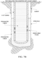
- FIG. 2 shows an exemplary setup in well 200, that is cemented 201 around tubing 205 having threaded ports 207 into which are fitted threaded plugs 209 (degradable tape 210 not visible). Also shown is top wiper plug 211, bottom wiper plug 213, burst disk 215, dual latch collar 217, and float shoe 219. The degradation fluid 203 and contaminated cement and drillwater 221 are also shown.
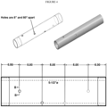
- the holed section of piping was installed in the shoe track above the latch collar, and the ports stopped with plugs and sealant tape ( FIG. 3 , FIG. 5 ).
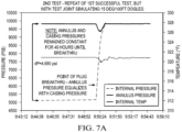
- the casing pressure was tested after bumping the cement plug. Plugs must hold pressure for minimum 12 hrs, but are also to dissolve in less than 48 hrs and flow to be established through the ports prior to frac operations.
- the test was performed at 160°C [320°F] and 68.9 MPa [10,000 psi].
- the plugs were for P110 casing size 5-1/2", 23 ppf.
- NexGen ® magnesium alloy plugs which are rated for a maximum pressure of 68.9 MPa [10,000 psi] at 93.3°C -160°C [200°F - 300°F]. These plugs dissolve in fresh water or 1%-3% KCL in 24-48 hours.
- the dissolving fluid used in our tests was drill water plus MMCR-MICRO MATRIX ® CEMENT RETARDER (MMCR) a liquid retarder designed for use in MICRO MATRIX ® cement.
- MMCR MMCR-MICRO MATRIX ® CEMENT RETARDER
- the plug/tape combination needed to hold pressure tests as follows:
- degradable materials by the same company include:
Landscapes
- Geology (AREA)
- Life Sciences & Earth Sciences (AREA)
- Engineering & Computer Science (AREA)
- Mining & Mineral Resources (AREA)
- Physics & Mathematics (AREA)
- Environmental & Geological Engineering (AREA)
- Fluid Mechanics (AREA)
- General Life Sciences & Earth Sciences (AREA)
- Geochemistry & Mineralogy (AREA)
- Chemical & Material Sciences (AREA)
- Chemical Kinetics & Catalysis (AREA)
- General Chemical & Material Sciences (AREA)
- Geophysics (AREA)
- Sealing Material Composition (AREA)
- Earth Drilling (AREA)
Claims (11)
- Verfahren zum zeitweiligen Verschließen eines Kohlenwasserstoffbohrlochs (200), umfassend:a) Bereitstellen eines Rohrabschnitts (205) in einem Bohrloch (200), wobei das Rohr (205) einen oder mehrere Gewindeanschlüsse (207) darin aufweist, wobei jeder von dem einen oder den mehreren Gewindeanschlüssen (207) einen abbaubaren Stopfen (209) mit Gewinde daran aufweist, wobei das Gewinde mit einem abbaubaren Gewindeband (210) umwickelt ist, wobei der abbaubare Stopfen (209) und das abbaubare Band (210) angeordnet sind, jeden von dem einen oder den mehreren Anschlüssen (207) zu verstopfen, um einen verschlossenen Abschnitt (205) des Bohrlochs (200) bereitzustellen;b) Durchführen einer Bohrlocharbeit in dem verschlossenen Abschnitt (205) des Bohrlochs (200) über einen Zeitraum; undc) Bereitstellen eines oder mehrerer abbauender Fluide (203) in dem Bohrloch an dem verschlossenen Abschnitt (205) des Bohrlochs (200), um den abbaubaren Stopfen (209) und das abbaubare Band abzubauen, wobei keine erkennbaren Feststoffe zurückbleiben, um dadurch den verschlossenen Bohrlochabschnitt (205) zu öffnen.
- Verfahren gemäß Anspruch 1, wobei der abbaubare Stopfen (209) und das abbaubare Band (210) in wässriger Lösung binnen weniger als 48 Stunden abbaubar sind.
- Verfahren gemäß Anspruch 2, wobei der abbaubare Stopfen (209) und das abbaubare Band (210), wenn gegenüber der wässrigen Lösung exponiert, binnen 48 Stunden oder weniger mehr als 80 % des Ausgangsgewichts verlieren.
- Verfahren gemäß Anspruch 2, wobei der abbaubare Stopfen (209) und das abbaubare Band (210), wenn gegenüber der wässrigen Lösung exponiert, binnen 24 Stunden oder weniger mehr als 80 % des Ausgangsgewichts verlieren.
- Verfahren gemäß Anspruch 1, wobei die Bohrlocharbeit Druckprüfung des verschlossenen Abschnitts (205) des Bohrlochs (200) umfasst.
- Verfahren gemäß Anspruch 1, wobei die Bohrlocharbeit Druckprüfung des verschlossenen Abschnitts (205) des Bohrlochs bei 34,4 Mpa (5000 psi) Druckunterschied für wenigstens 12 Stunden umfasst.
- Verfahren gemäß Anspruch 1, wobei die Bohrlocharbeit Druckprüfung des verschlossenen Abschnitts (205) des Bohrlochs (200) bei 68,8 Mpa (10000 psi) Druckunterschied für wenigstens 0,5 Stunden umfasst.
- Verfahren gemäß Anspruch 1, wobei das Verfahren ferner Bereitstellen einer oder mehrerer Blockiervorrichtungen über und unter dem Abschnitt umfasst, wobei die Blockiervorrichtungen ausgewählt sind aus einem Stopfen, einem Verschluss, einem Korb und Kombinationen davon.
- Verfahren gemäß Anspruch 1, wobei ein erstes abbauendes Fluid (203) das abbaubare Gewindeband (210) abbaut und ein zweites abbauendes Fluid (203) den abbaubaren Stopfen (209) abbaut.
- Verfahren gemäß Anspruch 1, wobei sich das abbaubare Gewindeband (210) in Rohöl bei einer Temperatur von bis zu 300°C für wenigstens einen Monat nicht abbaut.
- Kohlenwasserstoffbohrloch (200), wobei das Kohlenwasserstoffbohrloch (200) ein Rohr (205) in einem unterirdischen Kohlenwasserstoffreservoir umfasst, wobei das Rohr (205) eine Vielzahl von Löchern (207) darin aufweist, wobei eines oder mehrere der Löcher (207) mit einem abbaubaren Stopfen (209) blockiert sind, der ein Gewinde aufweist, wobei das Gewinde mit einem abbaubaren Band (210) umwickelt ist, das mit einem Abbaufluid (203) abbaubar ist, wobei keine erkennbaren Feststoffe erzeugt werden, wobei der abbaubare Stopfen, der die blockierten Löcher (207) blockiert, fähig ist, wenigstens 34,4 MPa (5000 psi) Druckunterschied für 12 Stunden zu widerstehen.
Applications Claiming Priority (2)
| Application Number | Priority Date | Filing Date | Title |
|---|---|---|---|
| US201862734191P | 2018-09-20 | 2018-09-20 | |
| PCT/US2019/052171 WO2020061463A1 (en) | 2018-09-20 | 2019-09-20 | Dissolvable thread tape and plugs for wells |
Publications (3)
| Publication Number | Publication Date |
|---|---|
| EP3853438A1 EP3853438A1 (de) | 2021-07-28 |
| EP3853438A4 EP3853438A4 (de) | 2022-04-06 |
| EP3853438B1 true EP3853438B1 (de) | 2023-05-10 |
Family
ID=69884171
Family Applications (1)
| Application Number | Title | Priority Date | Filing Date |
|---|---|---|---|
| EP19863493.3A Active EP3853438B1 (de) | 2018-09-20 | 2019-09-20 | Auflösbares gewindeband und stopfen für bohrlöcher |
Country Status (4)
| Country | Link |
|---|---|
| US (1) | US11053762B2 (de) |
| EP (1) | EP3853438B1 (de) |
| CA (1) | CA3113055C (de) |
| WO (1) | WO2020061463A1 (de) |
Families Citing this family (6)
| Publication number | Priority date | Publication date | Assignee | Title |
|---|---|---|---|---|
| US11414952B1 (en) * | 2018-10-12 | 2022-08-16 | Workover Solutions, Inc. | Dissolvable thread-sealant for downhole applications |
| US11459874B1 (en) * | 2019-04-01 | 2022-10-04 | Todd Stair | Shoe track assembly system and method of use |
| US20210388691A1 (en) * | 2020-06-11 | 2021-12-16 | Halliburton Energy Services,Inc. | Fluid communication method for hydraulic fracturing |
| US20220364429A1 (en) * | 2021-05-14 | 2022-11-17 | Conocophillips Company | Dissolvable plug removal with erosive tool |
| US11741275B2 (en) | 2021-10-22 | 2023-08-29 | Halliburton Energy Services, Inc. | Model-based selection of dissolvable sealing balls |
| GB2615099A (en) * | 2022-01-27 | 2023-08-02 | Hill Radtke Cameron | A pressure testable toe sleeve and a method for pressure testing a wellbore |
Family Cites Families (48)
| Publication number | Priority date | Publication date | Assignee | Title |
|---|---|---|---|---|
| US3273641A (en) | 1966-09-20 | Method and apparatus for completing wells | ||
| US3163218A (en) | 1960-03-14 | 1964-12-29 | Jersey Prod Res Co | Method of consolidating a formation using a heater within a liner which is thereafter destroyed |
| US3880233A (en) | 1974-07-03 | 1975-04-29 | Exxon Production Research Co | Well screen |
| US4018283A (en) | 1976-03-25 | 1977-04-19 | Exxon Production Research Company | Method and apparatus for gravel packing wells |
| US4202411A (en) | 1978-05-24 | 1980-05-13 | Baker International Corporation | Acid soluble coating for well screens |
| US4930573A (en) * | 1989-04-06 | 1990-06-05 | Otis Engineering Corporation | Dual hydraulic set packer |
| US5355956A (en) * | 1992-09-28 | 1994-10-18 | Halliburton Company | Plugged base pipe for sand control |
| US5320178A (en) | 1992-12-08 | 1994-06-14 | Atlantic Richfield Company | Sand control screen and installation method for wells |
| US5765641A (en) | 1994-05-02 | 1998-06-16 | Halliburton Energy Services, Inc. | Bidirectional disappearing plug |
| US5479986A (en) | 1994-05-02 | 1996-01-02 | Halliburton Company | Temporary plug system |
| US5837656A (en) | 1994-07-21 | 1998-11-17 | Santrol, Inc. | Well treatment fluid compatible self-consolidating particles |
| US5607017A (en) | 1995-07-03 | 1997-03-04 | Pes, Inc. | Dissolvable well plug |
| US6220350B1 (en) | 1998-12-01 | 2001-04-24 | Halliburton Energy Services, Inc. | High strength water soluble plug |
| US6380138B1 (en) | 1999-04-06 | 2002-04-30 | Fairmount Minerals Ltd. | Injection molded degradable casing perforation ball sealers fluid loss additive and method of use |
| US6651743B2 (en) * | 2001-05-24 | 2003-11-25 | Halliburton Energy Services, Inc. | Slim hole stage cementer and method |
| US7168494B2 (en) | 2004-03-18 | 2007-01-30 | Halliburton Energy Services, Inc. | Dissolvable downhole tools |
| US7409999B2 (en) | 2004-07-30 | 2008-08-12 | Baker Hughes Incorporated | Downhole inflow control device with shut-off feature |
| US7380600B2 (en) | 2004-09-01 | 2008-06-03 | Schlumberger Technology Corporation | Degradable material assisted diversion or isolation |
| US7673678B2 (en) | 2004-12-21 | 2010-03-09 | Schlumberger Technology Corporation | Flow control device with a permeable membrane |
| WO2006101618A2 (en) | 2005-03-18 | 2006-09-28 | Exxonmobil Upstream Research Company | Hydraulically controlled burst disk subs (hcbs) |
| US7493956B2 (en) | 2006-03-16 | 2009-02-24 | Baker Hughes Incorporated | Subsurface safety valve with closure provided by the flowing medium |
| US7527103B2 (en) | 2007-05-29 | 2009-05-05 | Baker Hughes Incorporated | Procedures and compositions for reservoir protection |
| US9163470B2 (en) | 2008-10-07 | 2015-10-20 | Schlumberger Technology Corporation | Multiple activation-device launcher for a cementing head |
| US8899317B2 (en) * | 2008-12-23 | 2014-12-02 | W. Lynn Frazier | Decomposable pumpdown ball for downhole plugs |
| US9506309B2 (en) * | 2008-12-23 | 2016-11-29 | Frazier Ball Invention, LLC | Downhole tools having non-toxic degradable elements |
| US9181772B2 (en) * | 2009-04-21 | 2015-11-10 | W. Lynn Frazier | Decomposable impediments for downhole plugs |
| US8276670B2 (en) | 2009-04-27 | 2012-10-02 | Schlumberger Technology Corporation | Downhole dissolvable plug |
| US8596295B2 (en) * | 2010-06-16 | 2013-12-03 | Mueller International, Llc | Mechanical position indicator |
| US9187977B2 (en) | 2010-07-22 | 2015-11-17 | Exxonmobil Upstream Research Company | System and method for stimulating a multi-zone well |
| US8887816B2 (en) | 2011-07-29 | 2014-11-18 | Halliburton Energy Services, Inc. | Polymer compositions for use in downhole tools and components thereof |
| US8596366B2 (en) | 2011-09-27 | 2013-12-03 | Halliburton Energy Services, Inc. | Wellbore flow control devices comprising coupled flow regulating assemblies and methods for use thereof |
| US10337279B2 (en) | 2014-04-02 | 2019-07-02 | Magnum Oil Tools International, Ltd. | Dissolvable downhole tools comprising both degradable polymer acid and degradable metal alloy elements |
| NO339382B1 (no) | 2012-01-10 | 2016-12-05 | Qinterra Tech As | Framgangsmåte og anordning for å fjerne en hydratplugg |
| US20130220599A1 (en) * | 2012-02-24 | 2013-08-29 | Colin Gordon Rae | External Pressure Testing of Gas Lift Valve in Side-Pocket Mandrel |
| US9151143B2 (en) | 2012-07-19 | 2015-10-06 | Halliburton Energy Services, Inc. | Sacrificial plug for use with a well screen assembly |
| GB2503561B (en) * | 2013-05-08 | 2014-09-10 | Verderg Connectors Ltd | Plug for subsea components |
| EP3017141B1 (de) | 2013-07-01 | 2021-03-03 | ConocoPhillips Company | Stopfen aus einer schmelzbaren legierung in einer durchflussregelungsvorrichtung |
| US9856714B2 (en) * | 2013-07-17 | 2018-01-02 | Weatherford Technology Holdings, Llc | Zone select stage tool system |
| US20150119301A1 (en) | 2013-10-31 | 2015-04-30 | Preferred Technology, Llc | Flash Coating Treatments For Proppant Solids |
| WO2015127177A1 (en) | 2014-02-21 | 2015-08-27 | Terves, Inc. | Manufacture of controlled rate dissolving materials |
| US10308807B2 (en) | 2016-06-01 | 2019-06-04 | Terves Inc. | Dissolvable rubber |
| US9739107B2 (en) * | 2014-02-21 | 2017-08-22 | Baker Hughes Incorporated | Removable downhole article with frangible protective coating, method of making, and method of using the same |
| US20150354310A1 (en) | 2014-06-05 | 2015-12-10 | General Plastics & Composites, L.P. | Dissolvable downhole plug |
| US10060213B2 (en) * | 2015-10-14 | 2018-08-28 | Baker Hughes, A Ge Company, Llc | Residual pressure differential removal mechanism for a setting device for a subterranean tool |
| WO2017116477A1 (en) * | 2015-12-31 | 2017-07-06 | Halliburton Energy Services, Inc. | Downhole tool with alterable structural component |
| CA3024478A1 (en) | 2016-05-16 | 2017-11-23 | Ecolab Usa Inc. | Slow-release scale inhibiting compositions |
| WO2018035472A1 (en) * | 2016-08-18 | 2018-02-22 | Conocophillips Company | Degradable pump in shoe |
| EP3336505B1 (de) * | 2016-12-15 | 2020-02-12 | INGU Solutions Inc. | Sensorvorrichtung und systeme zur bestimmung von fluidparametern |
-
2019
- 2019-09-20 US US16/577,509 patent/US11053762B2/en active Active
- 2019-09-20 WO PCT/US2019/052171 patent/WO2020061463A1/en unknown
- 2019-09-20 EP EP19863493.3A patent/EP3853438B1/de active Active
- 2019-09-20 CA CA3113055A patent/CA3113055C/en active Active
Also Published As
| Publication number | Publication date |
|---|---|
| CA3113055A1 (en) | 2020-03-26 |
| EP3853438A1 (de) | 2021-07-28 |
| CA3113055C (en) | 2022-09-27 |
| EP3853438A4 (de) | 2022-04-06 |
| US20200095840A1 (en) | 2020-03-26 |
| US11053762B2 (en) | 2021-07-06 |
| WO2020061463A1 (en) | 2020-03-26 |
Similar Documents
| Publication | Publication Date | Title |
|---|---|---|
| EP3853438B1 (de) | Auflösbares gewindeband und stopfen für bohrlöcher | |
| US10787884B2 (en) | Downhole tool having a dissolvable plug | |
| US9587475B2 (en) | Downhole tools having non-toxic degradable elements and their methods of use | |
| US7775285B2 (en) | Apparatus and method for servicing a wellbore | |
| US20110067889A1 (en) | Expandable and degradable downhole hydraulic regulating assembly | |
| US20110048743A1 (en) | Dissolvable bridge plug | |
| US11293253B2 (en) | Dual sub-surface release plug with bypass for small diameter liners | |
| US9581003B2 (en) | Completing a well in a reservoir | |
| EP3405647B1 (de) | Verfahren zur verzögerung des anschwellens eines packers durch integration einer löslichen metallummantelung | |
| WO2006028691A1 (en) | Shaped memory alloy for erosion control of downhole tools | |
| US8672030B2 (en) | System for cementing tubulars comprising a mud motor | |
| US20120318507A1 (en) | Hydrocarbon well and technique for perforating casing toe | |
| WO2012045060A2 (en) | Zonal contact with cementing and fracture treatment in one trip | |
| US11578539B2 (en) | Dissolvable connector for downhole application | |
| US20190106960A1 (en) | Pump down isolation plug | |
| US20220364429A1 (en) | Dissolvable plug removal with erosive tool | |
| US20240117707A1 (en) | Production sub including a fluid flow assembly having a pair of radial burst discs | |
| US20240139660A1 (en) | Fracture shield filter tool, method and system | |
| US20230250708A1 (en) | Bell nipple with annular preventers and coolant injection | |
| AU2021340967A1 (en) | Wiper plug system with anti-rotation feature | |
| Leighton et al. | Water Shutoff Using an Inflatable Composite Sleeve Polymerized In-Situ: A Case History on Forties Delta | |
| Kim et al. | Lessons Learned on the Open Hole Completions for the Two HPHT Retrograde Gas Condensate Fields Using Expandable Liner Hangers, External Sleeve Inflatable Packer Collars and Swell Packers for Zonal Isolation |
Legal Events
| Date | Code | Title | Description |
|---|---|---|---|
| STAA | Information on the status of an ep patent application or granted ep patent |
Free format text: STATUS: THE INTERNATIONAL PUBLICATION HAS BEEN MADE |
|
| PUAI | Public reference made under article 153(3) epc to a published international application that has entered the european phase |
Free format text: ORIGINAL CODE: 0009012 |
|
| STAA | Information on the status of an ep patent application or granted ep patent |
Free format text: STATUS: REQUEST FOR EXAMINATION WAS MADE |
|
| 17P | Request for examination filed |
Effective date: 20210407 |
|
| AK | Designated contracting states |
Kind code of ref document: A1 Designated state(s): AL AT BE BG CH CY CZ DE DK EE ES FI FR GB GR HR HU IE IS IT LI LT LU LV MC MK MT NL NO PL PT RO RS SE SI SK SM TR |
|
| DAV | Request for validation of the european patent (deleted) | ||
| DAX | Request for extension of the european patent (deleted) | ||
| A4 | Supplementary search report drawn up and despatched |
Effective date: 20220310 |
|
| RIC1 | Information provided on ipc code assigned before grant |
Ipc: E21B 33/134 20060101ALI20220303BHEP Ipc: E21B 33/12 20060101AFI20220303BHEP |
|
| STAA | Information on the status of an ep patent application or granted ep patent |
Free format text: STATUS: EXAMINATION IS IN PROGRESS |
|
| 17Q | First examination report despatched |
Effective date: 20220615 |
|
| GRAP | Despatch of communication of intention to grant a patent |
Free format text: ORIGINAL CODE: EPIDOSNIGR1 |
|
| STAA | Information on the status of an ep patent application or granted ep patent |
Free format text: STATUS: GRANT OF PATENT IS INTENDED |
|
| INTG | Intention to grant announced |
Effective date: 20221207 |
|
| GRAS | Grant fee paid |
Free format text: ORIGINAL CODE: EPIDOSNIGR3 |
|
| GRAA | (expected) grant |
Free format text: ORIGINAL CODE: 0009210 |
|
| STAA | Information on the status of an ep patent application or granted ep patent |
Free format text: STATUS: THE PATENT HAS BEEN GRANTED |
|
| AK | Designated contracting states |
Kind code of ref document: B1 Designated state(s): AL AT BE BG CH CY CZ DE DK EE ES FI FR GB GR HR HU IE IS IT LI LT LU LV MC MK MT NL NO PL PT RO RS SE SI SK SM TR |
|
| REG | Reference to a national code |
Ref country code: GB Ref legal event code: FG4D |
|
| REG | Reference to a national code |
Ref country code: AT Ref legal event code: REF Ref document number: 1566844 Country of ref document: AT Kind code of ref document: T Effective date: 20230515 Ref country code: CH Ref legal event code: EP |
|
| REG | Reference to a national code |
Ref country code: DE Ref legal event code: R096 Ref document number: 602019028906 Country of ref document: DE |
|
| REG | Reference to a national code |
Ref country code: IE Ref legal event code: FG4D |
|
| REG | Reference to a national code |
Ref country code: NO Ref legal event code: T2 Effective date: 20230510 |
|
| REG | Reference to a national code |
Ref country code: LT Ref legal event code: MG9D |
|
| REG | Reference to a national code |
Ref country code: NL Ref legal event code: MP Effective date: 20230510 |
|
| REG | Reference to a national code |
Ref country code: AT Ref legal event code: MK05 Ref document number: 1566844 Country of ref document: AT Kind code of ref document: T Effective date: 20230510 |
|
| PG25 | Lapsed in a contracting state [announced via postgrant information from national office to epo] |
Ref country code: SE Free format text: LAPSE BECAUSE OF FAILURE TO SUBMIT A TRANSLATION OF THE DESCRIPTION OR TO PAY THE FEE WITHIN THE PRESCRIBED TIME-LIMIT Effective date: 20230510 Ref country code: PT Free format text: LAPSE BECAUSE OF FAILURE TO SUBMIT A TRANSLATION OF THE DESCRIPTION OR TO PAY THE FEE WITHIN THE PRESCRIBED TIME-LIMIT Effective date: 20230911 Ref country code: NL Free format text: LAPSE BECAUSE OF FAILURE TO SUBMIT A TRANSLATION OF THE DESCRIPTION OR TO PAY THE FEE WITHIN THE PRESCRIBED TIME-LIMIT Effective date: 20230510 Ref country code: ES Free format text: LAPSE BECAUSE OF FAILURE TO SUBMIT A TRANSLATION OF THE DESCRIPTION OR TO PAY THE FEE WITHIN THE PRESCRIBED TIME-LIMIT Effective date: 20230510 Ref country code: AT Free format text: LAPSE BECAUSE OF FAILURE TO SUBMIT A TRANSLATION OF THE DESCRIPTION OR TO PAY THE FEE WITHIN THE PRESCRIBED TIME-LIMIT Effective date: 20230510 |
|
| PGFP | Annual fee paid to national office [announced via postgrant information from national office to epo] |
Ref country code: GB Payment date: 20230823 Year of fee payment: 5 |
|
| PG25 | Lapsed in a contracting state [announced via postgrant information from national office to epo] |
Ref country code: RS Free format text: LAPSE BECAUSE OF FAILURE TO SUBMIT A TRANSLATION OF THE DESCRIPTION OR TO PAY THE FEE WITHIN THE PRESCRIBED TIME-LIMIT Effective date: 20230510 Ref country code: PL Free format text: LAPSE BECAUSE OF FAILURE TO SUBMIT A TRANSLATION OF THE DESCRIPTION OR TO PAY THE FEE WITHIN THE PRESCRIBED TIME-LIMIT Effective date: 20230510 Ref country code: LV Free format text: LAPSE BECAUSE OF FAILURE TO SUBMIT A TRANSLATION OF THE DESCRIPTION OR TO PAY THE FEE WITHIN THE PRESCRIBED TIME-LIMIT Effective date: 20230510 Ref country code: LT Free format text: LAPSE BECAUSE OF FAILURE TO SUBMIT A TRANSLATION OF THE DESCRIPTION OR TO PAY THE FEE WITHIN THE PRESCRIBED TIME-LIMIT Effective date: 20230510 Ref country code: IS Free format text: LAPSE BECAUSE OF FAILURE TO SUBMIT A TRANSLATION OF THE DESCRIPTION OR TO PAY THE FEE WITHIN THE PRESCRIBED TIME-LIMIT Effective date: 20230910 Ref country code: HR Free format text: LAPSE BECAUSE OF FAILURE TO SUBMIT A TRANSLATION OF THE DESCRIPTION OR TO PAY THE FEE WITHIN THE PRESCRIBED TIME-LIMIT Effective date: 20230510 Ref country code: GR Free format text: LAPSE BECAUSE OF FAILURE TO SUBMIT A TRANSLATION OF THE DESCRIPTION OR TO PAY THE FEE WITHIN THE PRESCRIBED TIME-LIMIT Effective date: 20230811 |
|
| PG25 | Lapsed in a contracting state [announced via postgrant information from national office to epo] |
Ref country code: FI Free format text: LAPSE BECAUSE OF FAILURE TO SUBMIT A TRANSLATION OF THE DESCRIPTION OR TO PAY THE FEE WITHIN THE PRESCRIBED TIME-LIMIT Effective date: 20230510 |
|
| PG25 | Lapsed in a contracting state [announced via postgrant information from national office to epo] |
Ref country code: SK Free format text: LAPSE BECAUSE OF FAILURE TO SUBMIT A TRANSLATION OF THE DESCRIPTION OR TO PAY THE FEE WITHIN THE PRESCRIBED TIME-LIMIT Effective date: 20230510 |
|
| PG25 | Lapsed in a contracting state [announced via postgrant information from national office to epo] |
Ref country code: SM Free format text: LAPSE BECAUSE OF FAILURE TO SUBMIT A TRANSLATION OF THE DESCRIPTION OR TO PAY THE FEE WITHIN THE PRESCRIBED TIME-LIMIT Effective date: 20230510 Ref country code: SK Free format text: LAPSE BECAUSE OF FAILURE TO SUBMIT A TRANSLATION OF THE DESCRIPTION OR TO PAY THE FEE WITHIN THE PRESCRIBED TIME-LIMIT Effective date: 20230510 Ref country code: RO Free format text: LAPSE BECAUSE OF FAILURE TO SUBMIT A TRANSLATION OF THE DESCRIPTION OR TO PAY THE FEE WITHIN THE PRESCRIBED TIME-LIMIT Effective date: 20230510 Ref country code: EE Free format text: LAPSE BECAUSE OF FAILURE TO SUBMIT A TRANSLATION OF THE DESCRIPTION OR TO PAY THE FEE WITHIN THE PRESCRIBED TIME-LIMIT Effective date: 20230510 Ref country code: DK Free format text: LAPSE BECAUSE OF FAILURE TO SUBMIT A TRANSLATION OF THE DESCRIPTION OR TO PAY THE FEE WITHIN THE PRESCRIBED TIME-LIMIT Effective date: 20230510 Ref country code: CZ Free format text: LAPSE BECAUSE OF FAILURE TO SUBMIT A TRANSLATION OF THE DESCRIPTION OR TO PAY THE FEE WITHIN THE PRESCRIBED TIME-LIMIT Effective date: 20230510 |
|
| REG | Reference to a national code |
Ref country code: DE Ref legal event code: R097 Ref document number: 602019028906 Country of ref document: DE |
|
| P01 | Opt-out of the competence of the unified patent court (upc) registered |
Effective date: 20240117 |
|
| PLBE | No opposition filed within time limit |
Free format text: ORIGINAL CODE: 0009261 |
|
| STAA | Information on the status of an ep patent application or granted ep patent |
Free format text: STATUS: NO OPPOSITION FILED WITHIN TIME LIMIT |
|
| REG | Reference to a national code |
Ref country code: DE Ref legal event code: R119 Ref document number: 602019028906 Country of ref document: DE |
|
| 26N | No opposition filed |
Effective date: 20240213 |
|
| REG | Reference to a national code |
Ref country code: CH Ref legal event code: PL |
|
| PG25 | Lapsed in a contracting state [announced via postgrant information from national office to epo] |
Ref country code: SI Free format text: LAPSE BECAUSE OF FAILURE TO SUBMIT A TRANSLATION OF THE DESCRIPTION OR TO PAY THE FEE WITHIN THE PRESCRIBED TIME-LIMIT Effective date: 20230510 |
|
| PG25 | Lapsed in a contracting state [announced via postgrant information from national office to epo] |
Ref country code: LU Free format text: LAPSE BECAUSE OF NON-PAYMENT OF DUE FEES Effective date: 20230920 |