EP3853436B1 - Vorrichtung zur fernausrichtung einer injektorrohrführung - Google Patents
Vorrichtung zur fernausrichtung einer injektorrohrführung Download PDFInfo
- Publication number
- EP3853436B1 EP3853436B1 EP19863465.1A EP19863465A EP3853436B1 EP 3853436 B1 EP3853436 B1 EP 3853436B1 EP 19863465 A EP19863465 A EP 19863465A EP 3853436 B1 EP3853436 B1 EP 3853436B1
- Authority
- EP
- European Patent Office
- Prior art keywords
- guide
- coiled tubing
- mount
- guide mount
- injector
- Prior art date
- Legal status (The legal status is an assumption and is not a legal conclusion. Google has not performed a legal analysis and makes no representation as to the accuracy of the status listed.)
- Active
Links
Images


Classifications
-
- E—FIXED CONSTRUCTIONS
- E21—EARTH OR ROCK DRILLING; MINING
- E21B—EARTH OR ROCK DRILLING; OBTAINING OIL, GAS, WATER, SOLUBLE OR MELTABLE MATERIALS OR A SLURRY OF MINERALS FROM WELLS
- E21B19/00—Handling rods, casings, tubes or the like outside the borehole, e.g. in the derrick; Apparatus for feeding the rods or cables
- E21B19/22—Handling reeled pipe or rod units, e.g. flexible drilling pipes
-
- E—FIXED CONSTRUCTIONS
- E21—EARTH OR ROCK DRILLING; MINING
- E21B—EARTH OR ROCK DRILLING; OBTAINING OIL, GAS, WATER, SOLUBLE OR MELTABLE MATERIALS OR A SLURRY OF MINERALS FROM WELLS
- E21B17/00—Drilling rods or pipes; Flexible drill strings; Kellies; Drill collars; Sucker rods; Cables; Casings; Tubings
- E21B17/20—Flexible or articulated drilling pipes, e.g. flexible or articulated rods, pipes or cables
Definitions
- the present disclosure relates to coiled tubing units. More particularly, the present disclosure relates to coiled tubing injector guides for directing tubing into coiled tubing injectors. Still more particularly, the present disclosure relates to devices, systems, and methods for aligning coiled tubing injector guides and doing so remotely to avoid otherwise dangerous and cumbersome adjustments.
- Coiled tubing refers to a continuous string of pipe coiled on a take-up reel for transportation and handling.
- Coiled tubing is provided with outer diameters ranging from 19 mm to 101 mm(0.75 inches to 4 inches) and may be used in a wide range of oilfield services and operations throughout the life of a well.
- a coiled tubing unit may be a mobile or stationary vehicle or structure for performing coiled tubing operations at a well.
- a coiled tubing unit may often have a coiled tubing injector. The injector may drive or guide the tubing into a well for performing various oilfield services or operations.
- the coiled tubing unit may additionally have a coiled tubing guide, which may generally direct the tubing, as it is unspooled from a reel, into the injector.
- the guide may help to mitigate bends or kinks in the continuous tubing before it is fed into the injector and may be used to control alignment of the tubing as it enters the injector.
- the alignment of the tubing guide may be adjusted.
- Current systems as shown in FIGS. 4 and 5 , for example, include a threaded alignment shaft and a guide mount that is movable along the shaft.
- the guide mount may include a collar that is moveable along the shaft and large threaded nuts may be positioned on the shaft on either side of the collar. The nuts may be turned on the shaft causing them to travel along the shaft thereby adjusting the position of the collar along the shaft and thereby controlling the position of the guide mount.
- a locking nut may also be provided to secure the position once the mount is adjusted.
- Adjusting the above-described mechanism may be done manually to align the tubing guide with the injector. This alignment may be helpful to properly align the entering tubing with the injector chains.
- This manual adjustment may be done on the ground (i.e., during set up) or in a man lift basket. In the latter case, the lift basket may be 6-30 meter (20-100 feet) above the ground and an operator may use an extremely large wrench or wrenches to turn the nuts. Due to the difficulty in making these adjustments and/or due to the time required, the adjustment is often not performed or may only be performed at initial set up. This can cause issues to the machine or the tubing because the guide may not be in proper alignment with the injector causing the tubing to enter the injector out of alignment.
- US2004/211555 discloses a tubing guide for directing coiled tubing through an injector apparatus and into a well.
- a carrier is disclosed.
- the carrier has a plurality of segments pivotably connected to one another. The segments can pivot and thus the carrier itself can move from a fully retracted position to a fully rotated position.
- US5845708 discloses apparatus for handling pipe, coiled tubing, casing and conventional tubing in well drilling and servicing operations.
- US2008/314580 discloses an apparatus for conducting earth borehole operations, the apparatus having a base, a mast mounted on the base, and an integrated top drive/CT injector unit carried by the mast for longitudinal movement therealong.
- a coiled tubing injector system may include a coiled tubing injector guide configured for guiding coiled tubing into a coiled tubing injector and a remotely adjustable guide mechanism.
- the remotely adjustable guide mechanism may include a guide mount configured for adjustably securing the coiled tubing injector guide to a frame of the coiled tubing injector and a drive mechanism configured for remotely adjusting a position of the guide mount relative to the frame.
- a method of adjusting a guide mount of a coiled tubing injector guide on a coiled tubing injector may be provided.
- the method may include receiving a coiled tubing position from an operator.
- the method may also include sensing a position of at least one of the guide mount and coiled tubing passing through the injector.
- the method may also include adjusting the position of the guide mount to an aligned position to provide the coiled tubing position.
- the tubing guide may be operably connected to a drive mechanism that may remotely and controllably cause the tubing guide mount to translate across the top of a coiled tubing injector frame.
- the drive mechanism may be configured for precise controlled movement of the tubing guide mount so as to allow for precise alignment of the coiled tubing with the tubing injector.
- the system may also be configured to maintain its position once aligned to avoid inadvertent movement leading to further misalignment.
- the system may be advantageous particularly due to its ability to be adjusted remotely thereby avoiding the need for manual adjustment and exposure of personnel to dangerous elevated conditions.
- the system may be further advantageous due to is high level of precision under significant loading as well as its ability to maintain its position once aligned.
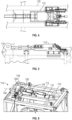
- a coiled tubing unit 100 may include a tubing spool 102 containing a very high linear footage of coiled tubing 104.
- the unit 100 may also include a coiled tubing injector 106 for advancing the tubing into a well and a coiled tubing guide 108 for guiding the tubing from the spool and into the injector 106.
- the injector 106 and the guide 108 may be supported by a crane and suspended above a well allowing the injector 106 to pull the tubing 104 from the spool 102 and through the guide 108 and advance the tubing 104 into the well.
- FIG. 2 is a side view of a tubing guide 108 in position on a tubing injector 106.
- the tubing guide 108 may be an arcuate structure configured for guiding the tubing 104 off of the spool 102 and into the injector 106.
- the injector 106 may be arranged within a frame 110 and the tubing guide 108 may be mounted on the frame.
- the tubing guide 108 may be secured to the frame of the injector so as to align the incoming tubing 104 with the injector 106 allowing the injector chains or other traction device to engage and advance the tubing.
- FIGS. 4 and 5 are top and side views, respectively, of the highlighted rectangular area of FIG. 3 .
- a tubing guide mount 112 may be arranged on the top of injector frame 110 and may be configured to slidably translate from side to side as shown in FIG. 5 .
- a threaded rod may extend through a collar on the rear portion of the mount 112 and the mount 112 and adjustment nuts may be used to control the position of the collar along the rod thereby controlling the position of the mount 112.
- the remotely adjustable tubing guide 108 may include a guide frame as depicted in FIGS. 2 and 3 .
- the guide frame may be pivotally secured to a tubing guide mount 112 and the tubing guide mount 112 may be slidingly positioned on a frame 110 of a tubing injector 106.
- the remotely adjustable tubing guide 108 may include a drive mechanism 114 for operably adjusting the tubing guide mount 112 and, thus, the position of the tubing guide frame.
- the remotely adjustable tubing guide may include the mentioned drive mechanism 114, a drive mount 116, and an interface bracket 118.
- the drive mechanism 114 may remotely and operably adjust the position of the interface bracket 118 relative to the drive mount 116 to adjust the position of the tubing guide 108.
- the drive mechanism 114 may be mounted to the drive mount 116 and may be configured for engagement with and adjustment of the interface bracket 118.
- the drive mechanism 114 may include an articulating element 120 such as an articulating and/or telescoping shaft.
- the drive mechanism 114 may cause the articulating element to advance or retract allowing for adjustment of the position of the interface bracket 118 and, thus, the guide mount 112.
- the drive mechanism 114 may include an electrically, pneumatically, hydraulically, or mechanically driven machine.
- the drive mechanism 114 may include a worm gear drive allowing for high levels of precision adjustment and an inherent or integrated locking mechanism for maintaining the position of the mount 112 when stopped.
- the worm gear may include a helical gear or worm wheel driven by a motor.
- An articulating element 120 in the form of a worm shaft may be arranged along a longitudinal axis generally tangential to and in plane with the worm wheel and may include a worm for engaging the helical gear.
- the worm shaft may include a rotation resisting feature.
- a key or keyway may be provided for rotationally engaging a keyway or key, respectively, on a fixed element. The key/keyway system may resist rotation of the worm shaft about the axis.
- the rotation resisting feature may be provided internally to the worm gear.
- the rotation resisting feature may be provided external to the worm gear and may be in the form of a brace, guide, or arm 122 on the interface bracket. That is, as shown, the interface bracket may include a horizontally extending tab, shoulder, or other frame engaging element. The frame engaging element may prevent and/or inhibit rotation of the interface bracket relative to the frame, but may allow the interface bracket to articulate horizontally along the frame and along the longitudinal axis of the articulating element.
- a bottom and a top tab may be provided to engage both a top surface of a frame element and a bottom surface of a frame element. Still other approaches to providing rotational resistance may be provided.
- the drive mount 116 may be configured for securing the position of the drive mechanism 114 and providing a secure stationary reference position.
- the drive mount 116 may be positioned on and secured to the injector frame.
- the drive mount may be secured on a front side of the injector frame as opposed to the rear side.
- the drive mechanism 114 may cause the guide mount 112 to translate toward and/or away from the drive mount 116.
- the drive mount 116 may include a face plate extending generally vertically from the injector frame. The plate may be welded, bolted, or otherwise securely fastened to the frame.
- the drive mount 116 may include brace plates on either side of the face plate to manage lateral loading on the face plate.
- the drive mount 116 and, for example, the face plate may include an opening 124 for allowing the articulating element 120 to extend through the drive mount 116 and articulate back and forth through the opening 124.
- the interface bracket 118 may be configured for establishing an interface between the drive mechanism 114 and the guide mount 112.
- the interface bracket 118 may be configured for securing to the drive mechanism 114 at one end and for securing to the guide mount 112 at an opposite end.
- the tubing guide may include a stabilization mechanism arranged at or near a pivot pin where the guide frame is secured to the guide mount.
- the stabilization mechanism may be the same or similar to the mechanism of U.S. Provisional Application No. 62/560,439 entitled Tubing Guide Stabilization Mechanism.
- the interface bracket 118 may be configured to avoid interference with the stabilization mechanism while it translates with the guide mount 112.
- the interface bracket 118 may include a laterally extending beam 126 and a pair of longitudinally extending struts or arms 128.
- the laterally extending beam 126 may be secured to and extend laterally from the articulating element 120 of the drive mechanism 114.
- the beam 126 may be pivotally secured to the articulating element 120 so as to allow the beam 126 to rotate about the longitudinal axis 130 or a key/keyway connection may be provided to resist relative rotation of the beam 126 and remaining portions of the interface bracket 118 about the longitudinal axis 130.
- the beam 126 may receive the articulating element 120 in a bore having a length along the longitudinal axis 130 sufficient to resist out of plane bending or rotation of the interface bracket 118 relative to the articulating element 120.
- the struts or arms 128 may extend longitudinally away from the beam 126 to the guide mount 112.
- the struts or arms 128 may be welded to the beam forming a unitary interface bracket 118. In other embodiments, the struts may be bolted or otherwise secured to the beam.
- the struts 128 may be arranged on either side of the stabilization mechanism maintaining clearance around the stabilization mechanism and engaging the guide mount 112.
- the struts or arms may each engage the guide mount and be secured thereto with a pin, a bolt, a welded connection, or another connection suitable to carry the loads from the drive mechanism and/or from the tubing guide 108.
- the present remotely adjustable mechanism is configured for retrofitting known or existing tubing guides by engaging the existing guide mounts or by replacing the guide mount on the existing systems with a slightly modified guide.
- the guide mount 112 may be modified from a conventional guide mount by including attachment features for securing the interfacing bracket to the guide mount 112.
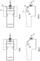
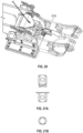
- a conventional guide mount is shown.
- FIG. 10 includes an attachment feature 136 for engaging the interfacing bracket and allowing for positional control of the guide mount.
- FIG. 11 shows a conventional guide mount
- FIG. 12 shows a guide mount with an attachment feature 136.
- the drive mechanism 114 may include wired or wireless communications systems in communication with a controller 132 for controlling the position of the guide mount 112. These systems may allow the drive mechanism to be actuated and controlled from a remote location.
- sensors 134 may be provided for sensing the position of the tubing guide mount relative to the frame and/or for sensing the position of the tubing entering the injector 106.
- the sensor or sensors 134 may be in wired or wireless communication with a display which may depict the position of the tubing 104, the relative position of the guide mount 112 and the frame or other absolute or relative positions. The user may rely on the absolute or relative positions of the elements to drive the drive mechanism and adjust the position of the guide mount so as to cause alignment of the coiled tubing with the tubing injector.
- the controller 132 may include a computer readable storage medium, a processor, and one or more input and output features.
- the controller 132 may include software, drivers, or other software stored on the computer readable storage medium for controlling the drive mechanism.
- the controller may also include control software adapted to select the position of the guide mount and/or the coiled tubing and instruct the drive mechanism to move the guide mount and the coiled tubing to a selected location.
- the selected location may be an aligned location where the coiled tubing is substantially center between traction units within the injector.
- the controller may, for example, include an input for an absolute or relative position of the coiled tubing and may have or include a stored relative dimension relating the position of the tubing to the position of the guide mount. As such, the controller may be able to adjust the guide mount to a position in order to locate the tubing at a desired location.
- the sensors 134 may include visual sensors, position sensors, load sensors, motor feedback devices, or other sensors.
- the sensors may be adapted to sense the position of the coiled tubing passing through the injector and may be adapted to sense the position of the guide mount on the frame of the injector.
- the positive mechanical connection between the drive mechanism and the guide mount may allow for reliance on motor feedback sensors to adjust the positions based on the assumption that a particular travel of the motor may cause a corresponding travel of the guide mount.
- the sensors may provide feedback to the user allowing for the system to be constantly calibrated to verify and control the stored relative position of the tubing and the guide mount. Still further, the sensors may provide continual, periodic, or selected feedback of the position of the coiled tubing passing through the injector.
- a method of operation 200 may be provided.
- a user may monitor the position of the coiled tubing passing through the injector 202 and may select a desired position of the coiled tubing 204.
- the system may store the desired position of the coiled tubing 206.
- the system may also continually, periodically, and/or selectively sense the actual position of the coiled tubing 208.
- the system may also sense the absolute position of the guide mount (e.g., relative to the frame) 210 and may also sense and/or calculate the relative position of the guide mount to the coiled tubing 212.
- the system may store one or more of these positions 214.
- the controller may be adapted to position the guide mount to locate the coiled tubing at the desired location 216.
- the controller may be adapted to automatically or, on command, return the guide mount to the stored absolute position 218.
- the relative position of the guide mount to the coiled tubing may change as systems wear, for example.
- the system may continually, periodically, or selectively sense the positions of the coiled tubing and the guide mount 220 and calculate a relative position 222. Where the value of the relative position changes, a new relative position may be stored 224 for use in properly positioning the guide mount and, thus, the coiled tubing.
- the interfacing bracket 318 may be secured to the guide mount 312 with a single securing pin 338 extending through each of the struts and two locations on the guide mount.
- the securing pin may include a single pin that secures the guide frame to the guide mount and the interfacing bracket may be secured to the guide mount with the single pin.
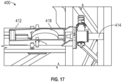
- FIGS. 16-17 include another remotely adjustable guide mechanism 400 for a tubing guide.
- this system is mounted on the front side of the guide mount 412 and includes an interfacing bracket 418 that involves extending the lateral sidewalls of the guide mount 412.
- the drive mechanism 414 may include a motorized drive such as a worm gear drive or other drive system. It is to be appreciated, that the circular element within the guide mount in these figures is showing the path of travel of the stabilization mechanism and is not intended to show a particular element of the design.
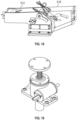
- FIGS. 18-25 include additional options and or details relating to extending the tubing guide mount and adapting it for engagement with a drive mechanism on a front side of the guide mount.
- the interfacing bracket 518 may include a series of plates welded onto the guide mount 512 and extending in a forward direction and supporting a cross beam with a collar, for example.
- the present series of plates and beams may be arranged to avoid interfering with the stabilization handle on the guide.
- the collar may be adapted to receive an articulating element of a drive mechanism to cause the guide mount 512 to articulate and allowing for alignment of the guide mount.
- the options shown in FIGS. 18-25 may be suitable for most any drive mechanism arranged on a front side of the guide mount 512.
- a similar interfacing bracket 618 is shown in FIG. 20 and another similar bracket 718 is shown in FIG. 22 .
- Still further similar brackets 818, 918 are shown in FIGS. 24 and 25 .
- a motorized worm gear has been shown as a drive mechanism and while the remotely controlled drive mechanism has been shown to be arranged on a front side of the guide mount, alternative approaches may be used.
- the drive mechanism may be arranged on a rear side of the guide mount similar to the manual system and alterative drive mechanisms may be used.
- One example of an alternative drive mechanism may include a hydraulic cylinder system to control the position of the guide mount.
- the drive mechanism 1014 may include one or more hydraulic cylinders secured to the frame and to the guide mount. The cylinders may be actuated to extend or retract and adjust the position of the guide mount.
- FIGS. 27 and 28 Another example of an alternative drive mechanism 1114 is shown in FIGS. 27 and 28 .
- a series of serrated saw blade type discs may be used in ratchet like fashion to rotate a shaft and control reverse motion.
- a gear reducing system 1214 may be used to allow for high-power and precise control over the position of the guide mount.
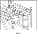
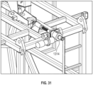
- FIGS. 30-31 Still another embodiment is shown in FIGS. 30-31 , where a worm gear type system 1314 is shown on a rear side of the guide mount.
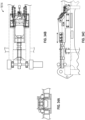
- FIG. 32 shows yet another embodiment of a remotely adjustable guide mechanism 1414.
- a hydraulic cylinder is used to adjust locking wedges that may be secured in place using one or more transversely positioned hydraulic cylinders.
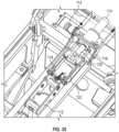
- FIG. 33 shows yet another embodiment of a remotely adjustable guide mechanism 1514.
- a hydraulic cylinder may be used to pivot a lever about a fulcrum to drive or retract the shaft and cause the guide mount to translate.
- FIG. 34 shows yet another embodiment of a remotely adjustable guide mechanism 1614.
- a rack and pinion system is used to translate the guide mount.
- Still other types of drive mechanisms may be used and may be arranged on the front or rear of the guide mount.
- the terms “substantially” or “generally” refer to the complete or nearly complete extent or degree of an action, characteristic, property, state, structure, item, or result.
- an object that is “substantially” or “generally” enclosed would mean that the object is either completely enclosed or nearly completely enclosed.
- the exact allowable degree of deviation from absolute completeness may in some cases depend on the specific context. However, generally speaking, the nearness of completion will be so as to have generally the same overall result as if absolute and total completion were obtained.
- the use of “substantially” or “generally” is equally applicable when used in a negative connotation to refer to the complete or near complete lack of an action, characteristic, property, state, structure, item, or result.
- an element, combination, embodiment, or composition that is "substantially free of” or “generally free of” an element may still actually contain such element as long as there is generally no significant effect thereof.
Landscapes
- Engineering & Computer Science (AREA)
- Geology (AREA)
- Life Sciences & Earth Sciences (AREA)
- Mining & Mineral Resources (AREA)
- Physics & Mathematics (AREA)
- Environmental & Geological Engineering (AREA)
- Fluid Mechanics (AREA)
- Mechanical Engineering (AREA)
- General Life Sciences & Earth Sciences (AREA)
- Geochemistry & Mineralogy (AREA)
- Earth Drilling (AREA)
- Placing Or Removing Of Piles Or Sheet Piles, Or Accessories Thereof (AREA)
- Winding, Rewinding, Material Storage Devices (AREA)
Claims (14)
- Coiled-Tubing-Injektorsystem, das umfasst:eine Coiled-Tubing-Injektorführung (108), die dazu ausgestaltet ist, das Coiled Tubing (104) in einen Coiled-Tubing-Injektor (106) zu führen, der innerhalb eines Gerüsts (110) angeordnet ist; undeine Steuerung (132); undeinen Führungsmechanismus, der umfasst:eine Führungshalterung (112), die dazu ausgestaltet ist, die Coiled-Tubing-Injektorführung (108) verstellbar an dem Gerüst (110) des Coiled-Tubing-Injektors (106) zu befestigen; undeinen Antriebsmechanismus (114) in Kommunikation mit der Steuerung (132) zum Betätigen des Antriebsmechanismus (114) von einem entfernt gelegenen Standort aus, um eine Seite-an-Seite-Position der Führungshalterung (112) relativ zu dem Gerüst (110) zu steuern, um das Coiled Tubing (104) mit dem Coiled-Tubing-Injektor (106) auszurichten.
- System nach Anspruch 1, wobei der Antriebsmechanismus (114) ein Artikulationselement (120) zum Steuern der Bewegung der Führungshalterung (112) umfasst.
- System nach Anspruch 2, das ferner einen Schnittstellenträger (118) zum Verbinden des Artikulationselements (120) mit der Führungshalterung (112) umfasst, wobei der Schnittstellenträger (118) wahlweise dazu ausgestaltet ist, einen Freiraum für einen Stabilisierungsmechanismus auf der Coiled-Tubing-Injektorführung (108) bereitzustellen.
- System nach Anspruch 1, das ferner eine Antriebshalterung (116) umfasst, die dazu ausgestaltet ist, den Antriebsmechanismus (114) zu befestigen und eine ortsfeste Referenzposition bereitzustellen; und/oder wobei der Antriebsmechanismus (114) einen elektrischen Antriebsmechanismus, einen hydraulischen Antriebsmechanismus und/oder einen pneumatischen Antriebsmechanismus umfasst.
- System nach Anspruch 1, das ferner ein Merkmal für optische Rückmeldung umfasst, wobei das Merkmal für optische Rückmeldung wahlweise dazu ausgestaltet ist, eine Position der Coiled-Tubing-Injektorführung an einem Bedienerstandort anzuzeigen.
- System nach Anspruch 1, wobei die Steuerung (132) dazu ausgestaltet ist, eine Position der Führungshalterung (112) zu speichern.
- System nach Anspruch 6, wobei die Steuerung (132) dazu ausgestaltet ist, den Antriebsmechanismus (114) zu steuern, um die Führungshalterung (112) an der gespeicherten Position zu positionieren.
- System nach Anspruch 7, wobei die Steuerung (132) dazu ausgestaltet ist, eine ausgewählte Position zu erfassen und zu berichten, wobei die Steuerung (132) wahlweise dazu ausgestaltet ist, die Führungshalterung (112) in die ausgewählte Position zu verstellen.
- Verfahren zum Verstellen einer Führungshalterung (112) einer Coiled-Tubing-Injektorführung (108) auf einem Coiled-Tubing-Injektor (106), wobei das Verfahren umfasst:Empfangen einer Coiled-Tubing-Position von einem Bediener;Erfassen einer Position der Führungshalterung (112) und/oder des Coiled Tubings (114), das durch den Injektor (106) verläuft; undVerstellen der Position der Führungshalterung (114) auf eine ausgerichtete Position, um die Coiled-Tubing-Position bereitzustellen.
- Verfahren nach Anspruch 9, das ferner das Speichern der ausgerichteten Position umfasst.
- Verfahren nach Anspruch 10, das ferner das Überwachen der Position der Führungshalterung (112) umfasst.
- Verfahren nach Anspruch 11, das ferner das Überwachen der Position des Coiled Tubings (104) umfasst, das durch den Injektor (106) verläuft.
- Verfahren nach Anspruch 12, das ferner das Berechnen und Speichern einer relativen Position der Führungshalterung (112) und des Coiled Tubings (104) umfasst.
- Verfahren nach Anspruch 13, das ferner das Verstellen der Position der Führungshalterung (112) umfasst und wahlweise ferner das Rückführen der Führungshalterung (112) in die ausgerichtete Position umfasst.
Applications Claiming Priority (2)
| Application Number | Priority Date | Filing Date | Title |
|---|---|---|---|
| US201862732292P | 2018-09-17 | 2018-09-17 | |
| PCT/US2019/051443 WO2020060998A1 (en) | 2018-09-17 | 2019-09-17 | Injector remote tubing guide alignment device |
Publications (3)
| Publication Number | Publication Date |
|---|---|
| EP3853436A1 EP3853436A1 (de) | 2021-07-28 |
| EP3853436A4 EP3853436A4 (de) | 2022-05-18 |
| EP3853436B1 true EP3853436B1 (de) | 2025-05-07 |
Family
ID=69887952
Family Applications (1)
| Application Number | Title | Priority Date | Filing Date |
|---|---|---|---|
| EP19863465.1A Active EP3853436B1 (de) | 2018-09-17 | 2019-09-17 | Vorrichtung zur fernausrichtung einer injektorrohrführung |
Country Status (5)
| Country | Link |
|---|---|
| US (1) | US11608695B2 (de) |
| EP (1) | EP3853436B1 (de) |
| CA (1) | CA3112576A1 (de) |
| SA (1) | SA521421468B1 (de) |
| WO (1) | WO2020060998A1 (de) |
Families Citing this family (4)
| Publication number | Priority date | Publication date | Assignee | Title |
|---|---|---|---|---|
| CA3017404C (en) | 2017-09-19 | 2024-01-02 | National Oilwell Varco, L.P. | Tubing guide stabilization |
| EP3853436B1 (de) | 2018-09-17 | 2025-05-07 | Nov Intervention and Stimulation Equipment US, LLC | Vorrichtung zur fernausrichtung einer injektorrohrführung |
| EP3899194A1 (de) | 2018-12-19 | 2021-10-27 | Nov Intervention and Stimulation Equipment US, LLC | Rohrwendelinjektor mit greiferschuhträgerpositionsmonitor |
| WO2020223502A1 (en) | 2019-05-01 | 2020-11-05 | Nov Intervention And Stimulation Equipment Us, Llc | Chain wear sensor |
Family Cites Families (33)
| Publication number | Priority date | Publication date | Assignee | Title |
|---|---|---|---|---|
| US4585061A (en) | 1983-10-18 | 1986-04-29 | Hydra-Rig Incorporated | Apparatus for inserting and withdrawing coiled tubing with respect to a well |
| GB2222842B (en) * | 1988-09-16 | 1992-07-15 | Otis Eng Co | Method and apparatus for running coiled tubing in subsea wells |
| US5029642A (en) * | 1989-09-07 | 1991-07-09 | Crawford James B | Apparatus for carrying tool on coil tubing with shifting sub |
| US5845708A (en) * | 1995-03-10 | 1998-12-08 | Baker Hughes Incorporated | Coiled tubing apparatus |
| US5799731A (en) | 1996-04-17 | 1998-09-01 | Halliburton Company | Tubing guide with optimized profile and offset |
| US6158516A (en) * | 1998-12-02 | 2000-12-12 | Cudd Pressure Control, Inc. | Combined drilling apparatus and method |
| US6216780B1 (en) | 2000-01-26 | 2001-04-17 | Hydra Rig, Inc. | Coiled tubing injector with improved traction |
| US6681614B1 (en) | 2000-09-06 | 2004-01-27 | Daniel L. Riffe | Apparatus for testing co-efficient of friction of a road surface |
| US6719043B2 (en) | 2002-05-10 | 2004-04-13 | Halliburton Energy Services, Inc. | Coiled tubing injector apparatus |
| US7036578B2 (en) * | 2003-04-25 | 2006-05-02 | Halliburton Energy Services, Inc. | Tubing guide and coiled tubing injector |
| US7431097B2 (en) | 2004-11-10 | 2008-10-07 | Halliburton Energy Services, Inc. | Apparatus and method for injecting tubing into a well |
| US7284618B2 (en) | 2005-01-27 | 2007-10-23 | Bob Geddes | Method and a device for automated control of coil pipe operations |
| US7681632B2 (en) * | 2005-11-17 | 2010-03-23 | Xtreme Coil Drilling Corp. | Integrated top drive and coiled tubing injector |
| US8215417B2 (en) | 2007-01-23 | 2012-07-10 | Canrig Drilling Technology Ltd. | Method, device and system for drilling rig modification |
| GB0719804D0 (en) | 2007-09-29 | 2007-11-21 | Renold Plc | Transmission chain wear monitoring |
| US7708058B1 (en) * | 2009-03-18 | 2010-05-04 | Rri Holdings, Inc. | Selectably elevatable injector for coiled tubing |
| WO2011107889A2 (en) * | 2010-03-03 | 2011-09-09 | Xtreme Coil Drilling Corp. | Coiled tubing injector assembly |
| US8789585B2 (en) * | 2010-10-07 | 2014-07-29 | Schlumberger Technology Corporation | Cable monitoring in coiled tubing |
| CA2820157C (en) | 2012-06-29 | 2019-07-30 | Sage Energy Development Ltd. | Mobile coiled tubing reel unit, rig and arrangements thereof |
| US9221618B2 (en) | 2012-11-06 | 2015-12-29 | AMF automation Technologies, LLC | Oven chain measurement system |
| TWI481841B (zh) | 2012-12-26 | 2015-04-21 | Kmc Chain Ind Co Ltd | Multi-function gauge |
| US9581009B2 (en) | 2013-10-15 | 2017-02-28 | National Oilwell Varco, L.P. | Coiled tubing injector with load sensing tubing guide |
| BR112016007645A2 (pt) * | 2013-11-19 | 2017-08-01 | Halliburton Energy Services Inc | aparelho injetor, sistema de injetor e suporte de cunha e método para mover um elemento tubular para dentro e para fora de um poço |
| US9797209B2 (en) * | 2013-11-25 | 2017-10-24 | Halliburton Energy Services, Inc. | Use of multiple stacked coiled tubing (CT) injectors for running hybrid strings of CT and jointed pipe or multiple CT string |
| US9732571B2 (en) | 2014-11-19 | 2017-08-15 | Stimline As | Injector head chain synchronization device |
| CA2971423C (en) | 2015-02-13 | 2019-08-13 | Halliburton Energy Services, Inc. | Real-time tracking and mitigating of bending fatigue in coiled tubing |
| WO2017105411A1 (en) | 2015-12-15 | 2017-06-22 | Halliburton Energy Services, Inc. | Real time tracking of bending forces and fatigue in a tubing guide |
| US9822613B2 (en) | 2016-03-09 | 2017-11-21 | Oceaneering International, Inc. | System and method for riserless subsea well interventions |
| DE102017119301A1 (de) | 2017-08-23 | 2019-02-28 | Iwis Antriebssysteme Gmbh & Co. Kg | Vorrichtung und Verfahren zur Ermittlung des Verschleisszustandes einer Kette |
| CA3017404C (en) | 2017-09-19 | 2024-01-02 | National Oilwell Varco, L.P. | Tubing guide stabilization |
| EP3853436B1 (de) | 2018-09-17 | 2025-05-07 | Nov Intervention and Stimulation Equipment US, LLC | Vorrichtung zur fernausrichtung einer injektorrohrführung |
| EP3899194A1 (de) | 2018-12-19 | 2021-10-27 | Nov Intervention and Stimulation Equipment US, LLC | Rohrwendelinjektor mit greiferschuhträgerpositionsmonitor |
| WO2020223502A1 (en) | 2019-05-01 | 2020-11-05 | Nov Intervention And Stimulation Equipment Us, Llc | Chain wear sensor |
-
2019
- 2019-09-17 EP EP19863465.1A patent/EP3853436B1/de active Active
- 2019-09-17 US US17/250,799 patent/US11608695B2/en active Active
- 2019-09-17 CA CA3112576A patent/CA3112576A1/en active Pending
- 2019-09-17 WO PCT/US2019/051443 patent/WO2020060998A1/en not_active Ceased
-
2021
- 2021-03-15 SA SA521421468A patent/SA521421468B1/ar unknown
Also Published As
| Publication number | Publication date |
|---|---|
| CA3112576A1 (en) | 2020-03-26 |
| EP3853436A1 (de) | 2021-07-28 |
| US11608695B2 (en) | 2023-03-21 |
| WO2020060998A1 (en) | 2020-03-26 |
| EP3853436A4 (de) | 2022-05-18 |
| SA521421468B1 (ar) | 2023-06-01 |
| US20210207445A1 (en) | 2021-07-08 |
Similar Documents
| Publication | Publication Date | Title |
|---|---|---|
| EP3853436B1 (de) | Vorrichtung zur fernausrichtung einer injektorrohrführung | |
| US10919726B2 (en) | Wireline system and methods of using same | |
| CA2757277C (en) | Raise-assist and smart energy system for a pipe handling apparatus | |
| US8671626B1 (en) | Apparatus and method for a drilling rig assembly | |
| EP3095956B1 (de) | Handhabungselement für injektor mit gewickeltem rohr | |
| EP1971752B1 (de) | Unterstützung des hebe- und senkmechanismus einer betonsäge | |
| US7779902B2 (en) | Arm for moving flexible lines at a wellsite | |
| US8251616B2 (en) | Method and apparatus for pile driving | |
| US9776265B2 (en) | System, method and retractable and/or folding apparatus for cutting an object | |
| US12234728B2 (en) | Horizontal directional drilling system with operator lift | |
| US9556688B2 (en) | Raise-assist and smart energy system for a pipe handling apparatus | |
| US7284618B2 (en) | Method and a device for automated control of coil pipe operations | |
| CN216441945U (zh) | 一种新型角度旋转平台 | |
| EP0252273A2 (de) | Einrichtung zum Be- und Entladen von palettierten Gegenständen in und aus wärmeisolierten Lieferwagen oder Containern | |
| EP1985567A2 (de) | System und Verfahren zum Spulen von Rohrstrang | |
| CA2906330C (en) | Raise-assist and smart energy system for a pipe handling apparatus | |
| US20150273598A1 (en) | Transportable horizontal bandsaw assembly | |
| CN116946273A (zh) | 用于带电作业的载人装置 | |
| US20250066173A1 (en) | Rotary sensor mount for lift device | |
| CN117410887B (zh) | 一种电缆敷设系统、速度控制方法及使用方法 | |
| EP4118290B1 (de) | Bohreinheit | |
| US20230159299A1 (en) | Rotating reel system | |
| CN119263000A (zh) | 用于电力电缆施工的移动式放线设备及放线方法 |
Legal Events
| Date | Code | Title | Description |
|---|---|---|---|
| STAA | Information on the status of an ep patent application or granted ep patent |
Free format text: STATUS: THE INTERNATIONAL PUBLICATION HAS BEEN MADE |
|
| PUAI | Public reference made under article 153(3) epc to a published international application that has entered the european phase |
Free format text: ORIGINAL CODE: 0009012 |
|
| STAA | Information on the status of an ep patent application or granted ep patent |
Free format text: STATUS: REQUEST FOR EXAMINATION WAS MADE |
|
| 17P | Request for examination filed |
Effective date: 20210316 |
|
| AK | Designated contracting states |
Kind code of ref document: A1 Designated state(s): AL AT BE BG CH CY CZ DE DK EE ES FI FR GB GR HR HU IE IS IT LI LT LU LV MC MK MT NL NO PL PT RO RS SE SI SK SM TR |
|
| DAV | Request for validation of the european patent (deleted) | ||
| DAX | Request for extension of the european patent (deleted) | ||
| A4 | Supplementary search report drawn up and despatched |
Effective date: 20220419 |
|
| RIC1 | Information provided on ipc code assigned before grant |
Ipc: E21B 41/04 20060101ALI20220411BHEP Ipc: E21B 19/08 20060101ALI20220411BHEP Ipc: E21B 17/20 20060101ALI20220411BHEP Ipc: E21B 15/00 20060101ALI20220411BHEP Ipc: B65H 49/20 20060101ALI20220411BHEP Ipc: E21B 19/22 20060101AFI20220411BHEP |
|
| P01 | Opt-out of the competence of the unified patent court (upc) registered |
Effective date: 20230530 |
|
| GRAP | Despatch of communication of intention to grant a patent |
Free format text: ORIGINAL CODE: EPIDOSNIGR1 |
|
| STAA | Information on the status of an ep patent application or granted ep patent |
Free format text: STATUS: GRANT OF PATENT IS INTENDED |
|
| INTG | Intention to grant announced |
Effective date: 20241204 |
|
| GRAS | Grant fee paid |
Free format text: ORIGINAL CODE: EPIDOSNIGR3 |
|
| GRAA | (expected) grant |
Free format text: ORIGINAL CODE: 0009210 |
|
| STAA | Information on the status of an ep patent application or granted ep patent |
Free format text: STATUS: THE PATENT HAS BEEN GRANTED |
|
| AK | Designated contracting states |
Kind code of ref document: B1 Designated state(s): AL AT BE BG CH CY CZ DE DK EE ES FI FR GB GR HR HU IE IS IT LI LT LU LV MC MK MT NL NO PL PT RO RS SE SI SK SM TR |
|
| REG | Reference to a national code |
Ref country code: GB Ref legal event code: FG4D |
|
| REG | Reference to a national code |
Ref country code: CH Ref legal event code: EP |
|
| REG | Reference to a national code |
Ref country code: DE Ref legal event code: R096 Ref document number: 602019069767 Country of ref document: DE |
|
| REG | Reference to a national code |
Ref country code: IE Ref legal event code: FG4D |
|
| REG | Reference to a national code |
Ref country code: NL Ref legal event code: MP Effective date: 20250507 |
|
| PG25 | Lapsed in a contracting state [announced via postgrant information from national office to epo] |
Ref country code: FI Free format text: LAPSE BECAUSE OF FAILURE TO SUBMIT A TRANSLATION OF THE DESCRIPTION OR TO PAY THE FEE WITHIN THE PRESCRIBED TIME-LIMIT Effective date: 20250507 Ref country code: ES Free format text: LAPSE BECAUSE OF FAILURE TO SUBMIT A TRANSLATION OF THE DESCRIPTION OR TO PAY THE FEE WITHIN THE PRESCRIBED TIME-LIMIT Effective date: 20250507 Ref country code: PT Free format text: LAPSE BECAUSE OF FAILURE TO SUBMIT A TRANSLATION OF THE DESCRIPTION OR TO PAY THE FEE WITHIN THE PRESCRIBED TIME-LIMIT Effective date: 20250908 |
|
| PGFP | Annual fee paid to national office [announced via postgrant information from national office to epo] |
Ref country code: DE Payment date: 20250702 Year of fee payment: 7 |
|
| REG | Reference to a national code |
Ref country code: LT Ref legal event code: MG9D |
|
| PG25 | Lapsed in a contracting state [announced via postgrant information from national office to epo] |
Ref country code: GR Free format text: LAPSE BECAUSE OF FAILURE TO SUBMIT A TRANSLATION OF THE DESCRIPTION OR TO PAY THE FEE WITHIN THE PRESCRIBED TIME-LIMIT Effective date: 20250808 |
|
| PGFP | Annual fee paid to national office [announced via postgrant information from national office to epo] |
Ref country code: NO Payment date: 20250909 Year of fee payment: 7 |
|
| PG25 | Lapsed in a contracting state [announced via postgrant information from national office to epo] |
Ref country code: PL Free format text: LAPSE BECAUSE OF FAILURE TO SUBMIT A TRANSLATION OF THE DESCRIPTION OR TO PAY THE FEE WITHIN THE PRESCRIBED TIME-LIMIT Effective date: 20250507 Ref country code: NL Free format text: LAPSE BECAUSE OF FAILURE TO SUBMIT A TRANSLATION OF THE DESCRIPTION OR TO PAY THE FEE WITHIN THE PRESCRIBED TIME-LIMIT Effective date: 20250507 |
|
| PGFP | Annual fee paid to national office [announced via postgrant information from national office to epo] |
Ref country code: IT Payment date: 20250825 Year of fee payment: 7 |
|
| REG | Reference to a national code |
Ref country code: AT Ref legal event code: MK05 Ref document number: 1792652 Country of ref document: AT Kind code of ref document: T Effective date: 20250507 |
|
| PG25 | Lapsed in a contracting state [announced via postgrant information from national office to epo] |
Ref country code: BG Free format text: LAPSE BECAUSE OF FAILURE TO SUBMIT A TRANSLATION OF THE DESCRIPTION OR TO PAY THE FEE WITHIN THE PRESCRIBED TIME-LIMIT Effective date: 20250507 |
|
| PGFP | Annual fee paid to national office [announced via postgrant information from national office to epo] |
Ref country code: GB Payment date: 20250703 Year of fee payment: 7 |
|
| PG25 | Lapsed in a contracting state [announced via postgrant information from national office to epo] |
Ref country code: HR Free format text: LAPSE BECAUSE OF FAILURE TO SUBMIT A TRANSLATION OF THE DESCRIPTION OR TO PAY THE FEE WITHIN THE PRESCRIBED TIME-LIMIT Effective date: 20250507 |
|
| PG25 | Lapsed in a contracting state [announced via postgrant information from national office to epo] |
Ref country code: AT Free format text: LAPSE BECAUSE OF FAILURE TO SUBMIT A TRANSLATION OF THE DESCRIPTION OR TO PAY THE FEE WITHIN THE PRESCRIBED TIME-LIMIT Effective date: 20250507 |
|
| PGFP | Annual fee paid to national office [announced via postgrant information from national office to epo] |
Ref country code: FR Payment date: 20250708 Year of fee payment: 7 |
|
| PG25 | Lapsed in a contracting state [announced via postgrant information from national office to epo] |
Ref country code: RS Free format text: LAPSE BECAUSE OF FAILURE TO SUBMIT A TRANSLATION OF THE DESCRIPTION OR TO PAY THE FEE WITHIN THE PRESCRIBED TIME-LIMIT Effective date: 20250807 |
|
| PG25 | Lapsed in a contracting state [announced via postgrant information from national office to epo] |
Ref country code: IS Free format text: LAPSE BECAUSE OF FAILURE TO SUBMIT A TRANSLATION OF THE DESCRIPTION OR TO PAY THE FEE WITHIN THE PRESCRIBED TIME-LIMIT Effective date: 20250907 |
|
| PG25 | Lapsed in a contracting state [announced via postgrant information from national office to epo] |
Ref country code: LV Free format text: LAPSE BECAUSE OF FAILURE TO SUBMIT A TRANSLATION OF THE DESCRIPTION OR TO PAY THE FEE WITHIN THE PRESCRIBED TIME-LIMIT Effective date: 20250507 |
|
| PG25 | Lapsed in a contracting state [announced via postgrant information from national office to epo] |
Ref country code: SM Free format text: LAPSE BECAUSE OF FAILURE TO SUBMIT A TRANSLATION OF THE DESCRIPTION OR TO PAY THE FEE WITHIN THE PRESCRIBED TIME-LIMIT Effective date: 20250507 Ref country code: DK Free format text: LAPSE BECAUSE OF FAILURE TO SUBMIT A TRANSLATION OF THE DESCRIPTION OR TO PAY THE FEE WITHIN THE PRESCRIBED TIME-LIMIT Effective date: 20250507 |
|
| PG25 | Lapsed in a contracting state [announced via postgrant information from national office to epo] |
Ref country code: CZ Free format text: LAPSE BECAUSE OF FAILURE TO SUBMIT A TRANSLATION OF THE DESCRIPTION OR TO PAY THE FEE WITHIN THE PRESCRIBED TIME-LIMIT Effective date: 20250507 |
|
| PG25 | Lapsed in a contracting state [announced via postgrant information from national office to epo] |
Ref country code: EE Free format text: LAPSE BECAUSE OF FAILURE TO SUBMIT A TRANSLATION OF THE DESCRIPTION OR TO PAY THE FEE WITHIN THE PRESCRIBED TIME-LIMIT Effective date: 20250507 |
|
| PG25 | Lapsed in a contracting state [announced via postgrant information from national office to epo] |
Ref country code: RO Free format text: LAPSE BECAUSE OF FAILURE TO SUBMIT A TRANSLATION OF THE DESCRIPTION OR TO PAY THE FEE WITHIN THE PRESCRIBED TIME-LIMIT Effective date: 20250507 Ref country code: SK Free format text: LAPSE BECAUSE OF FAILURE TO SUBMIT A TRANSLATION OF THE DESCRIPTION OR TO PAY THE FEE WITHIN THE PRESCRIBED TIME-LIMIT Effective date: 20250507 |
|
| REG | Reference to a national code |
Ref country code: DE Ref legal event code: R097 Ref document number: 602019069767 Country of ref document: DE |
|
| PLBE | No opposition filed within time limit |
Free format text: ORIGINAL CODE: 0009261 |
|
| STAA | Information on the status of an ep patent application or granted ep patent |
Free format text: STATUS: NO OPPOSITION FILED WITHIN TIME LIMIT |
|
| REG | Reference to a national code |
Ref country code: CH Ref legal event code: L10 Free format text: ST27 STATUS EVENT CODE: U-0-0-L10-L00 (AS PROVIDED BY THE NATIONAL OFFICE) Effective date: 20260318 |
|
| 26N | No opposition filed |
Effective date: 20260210 |