EP3852926B1 - Probenahmevorrichtung, system mit der probenahmevorrichtung und verfahren - Google Patents
Probenahmevorrichtung, system mit der probenahmevorrichtung und verfahren Download PDFInfo
- Publication number
- EP3852926B1 EP3852926B1 EP19779118.9A EP19779118A EP3852926B1 EP 3852926 B1 EP3852926 B1 EP 3852926B1 EP 19779118 A EP19779118 A EP 19779118A EP 3852926 B1 EP3852926 B1 EP 3852926B1
- Authority
- EP
- European Patent Office
- Prior art keywords
- sample
- container
- opening
- well
- liquid
- Prior art date
- Legal status (The legal status is an assumption and is not a legal conclusion. Google has not performed a legal analysis and makes no representation as to the accuracy of the status listed.)
- Active
Links
Images


Classifications
-
- B—PERFORMING OPERATIONS; TRANSPORTING
- B01—PHYSICAL OR CHEMICAL PROCESSES OR APPARATUS IN GENERAL
- B01L—CHEMICAL OR PHYSICAL LABORATORY APPARATUS FOR GENERAL USE
- B01L3/00—Containers or dishes for laboratory use, e.g. laboratory glassware; Droppers
- B01L3/50—Containers for the purpose of retaining a material to be analysed, e.g. test tubes
- B01L3/502—Containers for the purpose of retaining a material to be analysed, e.g. test tubes with fluid transport, e.g. in multi-compartment structures
- B01L3/5021—Test tubes specially adapted for centrifugation purposes
-
- B—PERFORMING OPERATIONS; TRANSPORTING
- B01—PHYSICAL OR CHEMICAL PROCESSES OR APPARATUS IN GENERAL
- B01L—CHEMICAL OR PHYSICAL LABORATORY APPARATUS FOR GENERAL USE
- B01L3/00—Containers or dishes for laboratory use, e.g. laboratory glassware; Droppers
- B01L3/02—Burettes; Pipettes
- B01L3/021—Pipettes, i.e. with only one conduit for withdrawing and redistributing liquids
-
- B—PERFORMING OPERATIONS; TRANSPORTING
- B01—PHYSICAL OR CHEMICAL PROCESSES OR APPARATUS IN GENERAL
- B01L—CHEMICAL OR PHYSICAL LABORATORY APPARATUS FOR GENERAL USE
- B01L3/00—Containers or dishes for laboratory use, e.g. laboratory glassware; Droppers
- B01L3/50—Containers for the purpose of retaining a material to be analysed, e.g. test tubes
- B01L3/502—Containers for the purpose of retaining a material to be analysed, e.g. test tubes with fluid transport, e.g. in multi-compartment structures
- B01L3/5023—Containers for the purpose of retaining a material to be analysed, e.g. test tubes with fluid transport, e.g. in multi-compartment structures with a sample being transported to, and subsequently stored in an absorbent for analysis
-
- B—PERFORMING OPERATIONS; TRANSPORTING
- B01—PHYSICAL OR CHEMICAL PROCESSES OR APPARATUS IN GENERAL
- B01L—CHEMICAL OR PHYSICAL LABORATORY APPARATUS FOR GENERAL USE
- B01L2200/00—Solutions for specific problems relating to chemical or physical laboratory apparatus
- B01L2200/02—Adapting objects or devices to another
- B01L2200/025—Align devices or objects to ensure defined positions relative to each other
-
- B—PERFORMING OPERATIONS; TRANSPORTING
- B01—PHYSICAL OR CHEMICAL PROCESSES OR APPARATUS IN GENERAL
- B01L—CHEMICAL OR PHYSICAL LABORATORY APPARATUS FOR GENERAL USE
- B01L2200/00—Solutions for specific problems relating to chemical or physical laboratory apparatus
- B01L2200/02—Adapting objects or devices to another
- B01L2200/026—Fluid interfacing between devices or objects, e.g. connectors, inlet details
-
- B—PERFORMING OPERATIONS; TRANSPORTING
- B01—PHYSICAL OR CHEMICAL PROCESSES OR APPARATUS IN GENERAL
- B01L—CHEMICAL OR PHYSICAL LABORATORY APPARATUS FOR GENERAL USE
- B01L2200/00—Solutions for specific problems relating to chemical or physical laboratory apparatus
- B01L2200/06—Fluid handling related problems
- B01L2200/0605—Metering of fluids
-
- B—PERFORMING OPERATIONS; TRANSPORTING
- B01—PHYSICAL OR CHEMICAL PROCESSES OR APPARATUS IN GENERAL
- B01L—CHEMICAL OR PHYSICAL LABORATORY APPARATUS FOR GENERAL USE
- B01L2200/00—Solutions for specific problems relating to chemical or physical laboratory apparatus
- B01L2200/06—Fluid handling related problems
- B01L2200/0642—Filling fluids into wells by specific techniques
-
- B—PERFORMING OPERATIONS; TRANSPORTING
- B01—PHYSICAL OR CHEMICAL PROCESSES OR APPARATUS IN GENERAL
- B01L—CHEMICAL OR PHYSICAL LABORATORY APPARATUS FOR GENERAL USE
- B01L2200/00—Solutions for specific problems relating to chemical or physical laboratory apparatus
- B01L2200/06—Fluid handling related problems
- B01L2200/0689—Sealing
-
- B—PERFORMING OPERATIONS; TRANSPORTING
- B01—PHYSICAL OR CHEMICAL PROCESSES OR APPARATUS IN GENERAL
- B01L—CHEMICAL OR PHYSICAL LABORATORY APPARATUS FOR GENERAL USE
- B01L2300/00—Additional constructional details
- B01L2300/04—Closures and closing means
- B01L2300/046—Function or devices integrated in the closure
- B01L2300/047—Additional chamber, reservoir
-
- B—PERFORMING OPERATIONS; TRANSPORTING
- B01—PHYSICAL OR CHEMICAL PROCESSES OR APPARATUS IN GENERAL
- B01L—CHEMICAL OR PHYSICAL LABORATORY APPARATUS FOR GENERAL USE
- B01L2300/00—Additional constructional details
- B01L2300/06—Auxiliary integrated devices, integrated components
- B01L2300/0627—Sensor or part of a sensor is integrated
- B01L2300/0663—Whole sensors
-
- B—PERFORMING OPERATIONS; TRANSPORTING
- B01—PHYSICAL OR CHEMICAL PROCESSES OR APPARATUS IN GENERAL
- B01L—CHEMICAL OR PHYSICAL LABORATORY APPARATUS FOR GENERAL USE
- B01L2300/00—Additional constructional details
- B01L2300/06—Auxiliary integrated devices, integrated components
- B01L2300/0681—Filter
-
- B—PERFORMING OPERATIONS; TRANSPORTING
- B01—PHYSICAL OR CHEMICAL PROCESSES OR APPARATUS IN GENERAL
- B01L—CHEMICAL OR PHYSICAL LABORATORY APPARATUS FOR GENERAL USE
- B01L2300/00—Additional constructional details
- B01L2300/08—Geometry, shape and general structure
- B01L2300/0861—Configuration of multiple channels and/or chambers in a single devices
- B01L2300/087—Multiple sequential chambers
-
- B—PERFORMING OPERATIONS; TRANSPORTING
- B01—PHYSICAL OR CHEMICAL PROCESSES OR APPARATUS IN GENERAL
- B01L—CHEMICAL OR PHYSICAL LABORATORY APPARATUS FOR GENERAL USE
- B01L2400/00—Moving or stopping fluids
- B01L2400/04—Moving fluids with specific forces or mechanical means
- B01L2400/0403—Moving fluids with specific forces or mechanical means specific forces
- B01L2400/0409—Moving fluids with specific forces or mechanical means specific forces centrifugal forces
Definitions
- the present invention relates to a sample container and especially a sample container configured to be rotated to separate a sample and derive a fraction for use in a further process, where an analyte or liquid/fluid/surface in another container, provided in the sample container, is used.
- the invention relates to a sampling device as defined in claim 1, comprising a receptacle and a sample container; the receptacle having an inner material receiving space defined by a side wall portion, a bottom wall portion at a fist end of the receptacle and having a receptacle opening opposite the bottom wall portion in a second end of the receptacle opposite the first end; and the sample container being adapted to overlay the receptacle opening when collocated with the receptacle, the sample container including:
- the sample container may be adapted to provide a permanent closure of the receptacle opening and in other embodiments the sample container may be adapted to provide a temporary closure over the receptacle's open top.
- the latter embodiments have advantages that a single receptacle may be produced that can be employed for different purposes depending on the type of sample container with which it is collocated, this may reduce manufacturing costs of the receptacle; also the receptacle may be reusable, thus reducing cost of ownership.
- the container opening may be permanently open or may be initially overlaid and closed by the liquid impermeable barrier.
- the liquid impermeable barrier may be constructed of a frangible material which, when broken, permits access to the container.
- the container may comprise components or analytes which are desired for affecting the sample.
- the container may contain therein analytes or other components, such as reactive surfaces or beads, for performing e.g. a chemical reaction in or with the sample or otherwise converting the sample or a portion thereof before any further reaction involving the container, as described below.
- the receptacle has a bottom and side walls which are configured into an inner material receiving space to hold material which is to be sampled.
- the material is often a liquid or a suspension but may also be a gas, gel or other flowable material.
- the receptacle is usually made of a material or a material composition which does not alter, convert, absorb or leak the material which is to be sampled, if this is not directly desirable.
- the receptacle may if desired comprise a preservative, such as if the material to be sampled is easily degradable or if it is expected that the material to be sampled will be stored in the receptacle for a long time.
- the sample container may also comprise a filter and/or seal disposed to cover at least a section of the sample receiving portion.
- This filter and/or seal may advantageously prevent spilling of the material to be sampled and/or of other material located in the receptacle.
- the filter may be used for separating the material to be sampled into a filtered fraction which forms the sample allowed to reach the well and another fraction retained in the receptacle.
- the sample container in some embodiments comprises a material receiving bore in communication with the receptacle which, in some of these embodiments, is uncovered by any filter and/or seal.
- the sample well is configured to hold at least a portion of the fluid which passes through the sample receiving portion to form the sample and has a well opening.
- the well opening and the sample receiving portion may be located in a direction radially perpendicular to the longitudinal axis which passes through the open top and the bottom wall portion of the receptacle, the well and/or the well opening is then positioned radially outside of the sample receiving portion or, more generally stated, the well opening is located closer to an outer periphery of the sample container than is the sample receiving portion.
- the present sampling device is especially suited for rotation around the longitudinal axis for separating the material to be sampled to derive a fraction which is forced upwardly through the sample receiving portion to form a sample, a portion of which enters the well via the passageway.
- the material in the receptacle need not have different fractions with different densities, for example, so that a portion, merely, of the material is forced upwardly to form the sample, that portion being identical to the material remaining in the receptacle.
- the inner material receiving space is adapted to provide a variable volume, the reduction thereof, such as by squeezing it or by moving the bottom wall section thereof towards the open top, then causes the flowable fluid in the receptacle to move towards and through the sample receiving portion of the sample container.
- more fluid for example a gas, could be added to reduce the volume available to the flowable fluid material and thereby achieve the same movement effect.
- the relative longitudinal positions (positions projected along the longitudinal axis) of the sample receiving portion and the sample well are selected so that the fluid from the receptacle, forced upwardly and radially, leaves the sample receiving portion and some of it enters the sample well to form a sample. Then, the sample receiving portion may extend farther radially than the sample well, as long as the well opening is positioned correctly.
- a liquid passageway is provided extending from a first opening into the sample receiving portion to a second opening into the well opening of the sample well.
- the first opening may be the opening into the sample receiving portion, such as if the liquid is simply forced out of the sample receiving portion.
- the liquid passageway may be dedicated channel for moving the sample (portion) to the well opening and into the sample well, whereby it may have a separate, first, opening into the sample receiving portion.
- the second opening into the well opening may be the well opening per se or a dedicated opening from the passageway into the well.
- the first opening is positioned closer to a top portion than a bottom portion of the sample receiving portion.
- the material in the receptacle or a portion thereof is forced, typically radially outwardly and thus, upwardly against the direction of gravity and along the inside wall portions of the receptacle in a direction parallel to the longitudinal axis.
- the material then reaches the sample receiving portion, passing through it to form a sample, then to the first opening and is guided by the passageway to the second opening and into the sample well. Then, rotation/volume reduction may be stopped, so that a portion of the sample is now in the sample well.
- the side wall portion of the receptacle may be formed with the walls essentially parallel to the longitudinal axis, such as with a less than 5 degrees deviation from a direction parallel to the axis, so that the liquid movement during rotation is well behaved and easily controllable.
- the sample receiving portion is positioned at a first position projected onto the longitudinal axis, the well opening at a second longitudinal position projected onto the longitudinal axis and the container opening at a third longitudinal position projected onto the longitudinal axis, the third position being above the first and the second positions in a direction along the longitudinal axis going from the bottom wall portion to the open top.
- the liquid may be elevated to reach the second position and thus enter the well, without the liquid reaching the third position and thus is able to enter the container.
- the material forming the sample container in which the sample well and the container are formed then provides the liquid impermeable barrier preventing liquid entering the container from the sample receiving portion.
- the container may be sealed by the liquid impermeable barrier, which may be separate from the material comprising the sample container in which the sample well and the container are formed, to prevent liquid from entering the container before this is desired.
- multiple wells may be provided. This may e.g. be to increase a volume of sample contained by the sample container.
- the receptacle may be oval in cross section, so that the sample liquid is primarily forced upwardly in the portions the farthest from the centre (at the major axis). Then, one or more sample wells may be provided at these portions.
- the container may comprise an analyte, chemical substance, a reactive surface, or the like.
- the contents of the container thus may be used for creating a reaction with some or all of the sample comprised in the sample well(s).
- a portion of the contents of the container may be provided in the sample well(s), or vice versa.
- the sample well(s) and/or container may have a predetermined volume in general or a predetermined volume or quantity of the sample or analyte/chemical substance/surface, so that a controlled reaction may take place.
- multiple containers may be provided in order to increase the number of reactions or chemical reaction steps which the sample may be exposed to.
- a pipette may enter both the sample well and the container without having to alter its distance to the axis.
- the pipette or other dosing element may be movable only along the axis, where the sample container may be rotatable around the axis. Then, the pipette or other dosing element may enter both the sample well and the container merely by rotating the sample container and moving the pipette up and down along the axis.
- the second opening opens into a top portion of the sample well.
- the second opening may be provided at a lower position than the first opening. In this manner, the liquid will stay in the sample well, when the sample container is stationary.
- the sample container further comprises an opening, preferably located centrally with the longitudinal axis, from outside of the sample container to the receptacle.
- this central opening comprises a bore extending along a predetermined distance parallel to the axis, such as to terminate above the first and second distances, so that when rotated, the liquid, as it is forced radially outwards, will not exit from this bore.
- an edge may be provided between outer portions of the central opening and outer portions of the inner surface of the sample receiving portion, so that when forced outwardly, the liquid may reach this edge which may prevent the liquid from exiting the sample receiving portion.
- a filter may be provided at this position to filter the liquid leaving the sample receiving portion. This position of the central opening prevents the liquid from leaving the sample receiving portion unfiltered.
- a component for example an analyte, is present in the container.
- This component may be selected, based on the sample type, to perform a predetermined reaction, to make a sample preparation or to otherwise affect the sample in a desired manner.
- the component thus may act to, with the sample added thereto, result in a sample which is ready for, for example, a particular quantification or measurement.
- the sample container further comprises a sealing element, typically acting as the liquid impermeable barrier, sealing at least the container. In this manner, the contents of the container cannot escape neither can the container be contaminated.
- This seal may then be removed or pierced in order to remove liquid/analyte from the container or in order to add sample from the sample well thereto.
- the seal may also cover e.g. the well and/or the passageway in order to prevent sample from escaping during rotation and to guide the sample from the central sample receiving portion to the well. Then, the seal over the well may be broken or removed in order to gain access to the sample therein.
- the sample container further comprises an elongate channel comprising an elongate sampling element.
- the elongate sampling element may be an element exhibiting a change in a parameter depending on the presence or a concentration of a component of a liquid added thereto.
- a typical type of elongate sampling element is a dip stick or lateral flow device, such as an element comprising at least a portion capable of transporting liquid therein by capillary forces.
- liquid may be transported into the channel using a pump.
- Capillary forces may be created when the elongate sampling element comprises a woven or non-woven portion.
- This portion may then comprise therein or thereon a chemical substance causing a reaction visible to an observer or to a measuring instrument.
- This portion capable of transporting liquid preferably exists all along the length of the elongate sampling element, such as if the elongate sampling element was made of such material.
- the elongate sampling element, or a portion thereof or a material held thereby may be capable of changing a colour, or another optical property, such as an absorption, transmission, reflection or another parameter which may be detected optically, such as when forming a chemical bond, the vibration thereof may be detected.
- detectable parameters may be detected electronically, such as by a current generated or a current transported through the elongate sampling element.
- the sample container may comprise electrodes capable of feeding a current to or through the elongate sampling element.
- the sample container may comprise a window or other radiation transmissive element between the channel and the surroundings so that a colour change may be ascertained or a reflection/absorption/scattering may be detected by feeding radiation to the elongate sampling and/or receiving radiation therefrom.
- the elongate channel may be visible from a direction perpendicular to the longitudinal axis, such as if the elongate channel extends around the axis, or from a direction along the axis, such as if the elongate channel extends in a plane perpendicular to the axis, such as across an upper surface of the sample container.
- the channel may be open, so that the elongate sampling element may be provided therein, removed therefrom or replaced therein.
- the channel may be sealed to prevent degradation, contamination or loss of the elongate sampling element.
- the elongate channel opens into the container.
- the liquid in the container may flow into the channel and thus wet the elongate sampling element.
- the liquid transporting portion of the elongate sampling element may transport the liquid along the length of the elongate sampling element from the opening.
- the channel preferably is at least approximately the same longitudinal position, projected onto the axis, as the container.
- the channel may extend from an opening and downwardly so that gravity assists in transporting the liquid along the elongate sampling element.
- the channel may open into the well, if the resulting liquid to be tested is present in the well. Clearly the same considerations apply.
- the elongate channel may open into a second container.
- This second container may, as the first container, be configured so as to be incapable of receiving fluid from the sample receiving portion, the well or the passageway during normal operation.
- the second container may be empty, until liquid is added thereto, such as from the first container, such as after a chemical reaction in the first container has taken place.
- the second container itself may comprise further chemical compounds for performing additional reactions with the liquid before transmission into the channel and into the elongate sampling element.
- the second container may have a predetermined volume to ensure that the amount of liquid reaching the elongate sampling element is well defined.
- This second container may have an opening at least partly positioned within the above overlap of well opening and container opening, so that a pipette moving only up/down may also be able to transfer liquid to the second container.
- the second container and the oblong channel may be positioned above the central sample receiving portion, the well, the liquid passageway and even the first container, if desired.
- the sample container forms an attachable lid or closure of the sample receptacle.
- different configurations of sample container may be provided for different types of samples, where the same sample receptacles may be provided in bulk.
- the different sample containers may then be provided with special purpose components in the containers, so that different sample containers may be used for different sample types or different types of measurement.
- a selected sample container may be attached to a sample receptacle to be ready for a measurement. This attachment may be detachable or permanent. In the former adaption, sample receptacles may be reused if desired.
- a second aspect of the invention relates to a sample container for use in the sampling device of the first aspect.
- a third aspect of the invention relates to a system for handling a sample, the system comprising:
- the rotator may be any type of rotating arrangement, such as an element for engaging the sampling device and a motor or the like for rotating the element.
- a motor or the like for rotating the element.
- gears, bearings and the like may be provided if desired.
- any type of motor may be provided as may any type of controlling and/or sensing for controlling the rotation.
- the dispenser may be any type of dispenser, such as a liquid receiving element which may be introduced into or above a central container opening (or bore) when present, the sample well(s) and the container(s) in order to either deliver liquid/fluid or the like thereto or remove liquid/fluid or the like therefrom.
- the dispenser may comprise a pump or the like for transferring liquid or the like into the liquid receiving element and delivering the liquid therefrom.
- a reservoir may also be provided, if a liquid is desired delivered in a larger amount or to a number of sample containers.
- the dispenser may be configured to pierce or penetrate a cover layer or seal, such as above the sample well(s), the container(s) or the central container opening.
- dispensers may be provided. Thus, one dispenser may be used for dispensing into the central container opening and one dispenser may be used for transferring liquid between the sample well(s) and container(s). Multiple dispensers may be used if a swift operation is desired, or if the movement of dispensers is limited.
- the, or each, dispenser is at least translatable along a direction parallel to the longitudinal axis. This simplifies the overall dispenser or dispensing assembly, as only a linear movement is required. In this situation, the overlap between the radial positions of the openings of the sample well(s) and container(s) enables a single pipette to engage the well(s) and container(s).
- a fourth aspect of the invention relates to a method of handling a sample, the method comprising:
- the sampling device may be designed so that when the rotation forces the liquid outwardly and upwardly, the liquid may enter the passageway and then the well.
- a portion of the liquid in the well may be displaced to the container, or a portion of the substance of the container may be displaced to the well.
- This displacement may be performed using the above pipette, such as, if the relative positions of the well and container opening allow, a pipette moving only up and down.
- One or more further containers may be provided, and a portion of a sample liquid from the sample well or from a first container may be dosed to a further container and liquid from that further container dosed into another further container and so on to have an(other) chemical reaction take place.
- the above elongate channel may be provided with the elongate sampling element, so that liquid displaced thereto (via the first or second or further containers) may be transported into the elongate sampling element to cause a change which may then be determined by an observer or a measuring instrument.
- a colour change may be determined with the naked eye, for example, whereas a change in reflection or electrical properties may be determined by a measuring instrument.
- a fifth aspect of the invention relates to a method of operating the system according to the third aspect of the invention, the method comprising:
- the operating step may comprise:
- a first embodiment of a sample container 10 comprising annular body 8 formed with: a centrally located opening, here in the form of a bore 12; a sample receiving portion 14; a liquid passageway 16, here in the form of a collecting track, and a sample well 18.
- a container 20 is provided for holding a material.
- a longitudinal axis A through the centre of the sample container 10 is illustrated.
- the sample container 10 is configured to be rotated around the axis A so that a fluid, typically a liquid, present in a receptacle (not illustrated in this figure) below the sample container 10 is forced outwardly and thus upwardly through the sample receiving portion 14 and into the collecting track 16, which in the present embodiment flares outwardly away from the axis A to guide fluid from the sample receiving portion 14 towards the sample well 18 which will then collect at least some of the fluid that has entered the track 16.
- a fluid typically a liquid
- the fluid from the sample well 18 and material from the container 20 may be mixed to arrive at a process or result which may then be quantified if desired.
- a filter material (not shown in figure 1 ) may be provided to cover the sample receiving portion 14. Filtering may be desired if a liquid present below the sample receiving portion 14 is a suspension of a solid and a liquid, where the solid is not desired in the sample well 18.
- the present sample container 10 may be used for a myriad of purposes, such as tests or measurements.
- the sample container 10 may itself comprise a measuring element. Multiple types of measuring elements or elements taking part in the measurement may be provided.
- the measuring element may be a window or the like opening into the well/container so that an optical measurement may be carried out without removing the liquid or the like from the well/container.
- electrodes may be provided in the container/well for performing the measurement.
- FIG 2 an embodiment of a sample container 10' is seen which, in addition to the sample container 10 of figure 1 , has a second container 20' connected to an elongate, here oblong, channel 21.
- the oblong channel 21 extends generally parallel to an outer circumferential wall of the body 8 and has a dimension in the direction of the longitudinal axis A.
- a dip stick or other oblong assay element provides an elongate sampling element 23 capable of transporting liquid from the container 20' along its length may be inserted into the elongate, here oblong, channel 21 to lie with a reactive surface generally parallel with the longitudinal axis A.
- the dip stick 23 further comprises one or more components located on the reactive surface which are configured to react with or to a component in the transported liquid.
- Dip sticks or the like may be used for illustrating a pH of the liquid as well as for identifying a large number of other components.
- the dip sticks have at least a portion capable of transporting liquid usually due to capillary effect. Then, the liquid may be transported from the container 20' along the channel 21 in a controlled manner.
- the container 20' may be dimensioned to comprise a metered and controlled amount of liquid in order to ensure that the amount of liquid reaching the elongate sampling element 23 is controlled.
- dip sticks or the like change colour depending on the result of the reaction.
- the dip stick 23 then may be removed from the sample container 10' for ascertaining this colour change, or a window 25 may be provided so that the colour or colour change may be determined without removing this element from the sample container 10'.
- a filter material 14' is provided in this embodiment and overlies the sample receiving portion 14 of the sample container 10'.
- This embodiment then may be operated by transferring a portion of the liquid or other flowable material that has passed through the filter material 14' from the container 20 or sample well 18 to the container 20'.
- the container 20' may replace the container 20, so that any reaction desired may take place in the container 20'.
- a separate filter may be provided at the entrance into the channel 21 from the container 20'
- FIG 3 an alternative embodiment of a sample container 10" is illustrated in which the elongate sampling element 23 is provided in a horizontal plane in a horizontal tray which provides the elongate channel 21' again fed from the container 20'.
- the distribution over the width of the element 23 may be more even, which may be seen as an advantage.
- a window may be provided over the tray 21' and the element 23 in order to keep the element in place during rotation and to e.g. increase the shelf life of the sample container 10".
- the top of the sample container 10, 10', 10" is sealed, such as by a polymer/plastic layer in order to prevent contamination thereof.
- the seal then may seal the opening into the container 20 while allowing liquid access from the upper side of the sample receiving portion 14 and to the sample well 18.
- the container 20 may be provided with a seal to act as a liquid impermeable barrier in order to prevent loss, such as by evaporation, of any contents thereof which, in use, are intended to be reacted with sample from the sample well 18 and to prevent liquid in the sample well 18 entering the container 20.
- the seal is made penetrable, for example by a pipette, such as by having a sufficiently small layer thickness.
- the bore 12 may also be sealed in order to prevent ingress of unwanted material.
- An upper opening of the sample well 18 may be positioned below (when the axis A is vertical) the opening into the container 20, so that a stepped portion 8' of the body 8 which separates the two openings acts as a liquid impermeable barrier to prevent liquid in the sample well 18 entering the container 20.
- the sample container 10, 10', 10" has no openings from below and into the track 16, well 18 and container 20. In fact, it may be preferred that the sample container 10, 10', 10" has no liquid passages from its lower side to the upper side at positions farther from the axis A an outer radius of the filter 14'. In this manner, the liquid entering the space over the sample receiving portion 14 has passed through the filter 14'.
- the spinning of the liquid in the bore 12 or receptacle 22 may still provide any desired filtering (now based only on density), so that only the desired liquid enters the track 16 and well 18 and not the container 20.
- the container 20 is accessible only from the upper side of the sample container 10, 10', 10".
- the sample container 10' forms a lid collocated with a receptacle 22 for receiving the liquid and together constitute a sampling device 24 according to the present invention.
- the filter 14' may be left out if desired, and different numbers of containers 20 or sizes of containers 20 may be provided as may different contents of the container(s) 20.
- the container(s) 20 may comprise a liquid, a powder, pellets, gas, reactive surfaces or the like. The contents of the container 20 may be metered to a particular amount if desired.
- sample containers 10, 10', 10" may be provided for a wide range of liquids, samples or the like and may be configured to different types of processes or reactions.
- the same receptacle 22 or the same shape thereof may be used for a number of different sample containers or lids 10, 10', 10".
- the sampling device 24 is illustrated together with a dosing apparatus 30 comprising two pipettes or needles 32 and 34, provided on a pipette boom 31, where the pipette 32 is positioned directly above the central bore 12, such as on the longitudinal axis A, in order to dispense a liquid into the central bore 12 for transfer into the receptacle 22.
- the pipette 34 is positioned above the container 20 but may also be positioned above the well 18, if the sampling device 24 is rotated around the axis A (solid arrow).
- a rotator such as a rotatable motor, (not illustrated) may be provided for rotating the sampling device 24 around the axis A, which preferably is a symmetry axis of the sampling device 24.
- the pipette boom 31 may be translated upwardly and downwardly, such as along the longitudinal axis A, which normally, at least during rotation, is vertical. This simple translation and rotation nevertheless will allow the two pipettes 32,34 to both transfer liquid to the bore 12 as well as transfer liquid or the like between the sample well 18 and container 20.
- the sample well 18 and the container 20 may be engaged by the same pipette 34 simply by rotating the sampling device 24 around the longitudinal axis A.
- the container 20 and sample well 18 should be accessible at the same distance from the axis A.
- the minimum and maximum radius - r-min and r-max - are illustrated at which the container 20 may be accessed.
- the same constraints will clearly be true for similar access to any container 20' connected to the elongate channel provided by oblong channel 21 or tray 21'.
- the sample well 18, in figure 1 also extends between r-min and r-max, but this is not a requirement.
- r-min and r-max distances may be selected for the well, as long as the intervals defined by the r-max and r-min values for the container(s) 20, 20' and sample well 18 have an overlap, which is a distance from the axis A at which both may be accessed preferably from directly above.
- any resulting liquid or the like from the container 20 or sample well 18 may be used for a measurement or a determination of properties thereof. Then, that liquid or the like may be transferred from the well/container to a measuring instrument if desired.
- a liquid dispensed via bore 12 into the receptacle 22 may be the liquid desired in the sample well 18 or may be one component of a liquid to be tested.
- the liquid in the receptacle 22 may be arrived at by e.g. mixing a liquid and another fraction, which may be solid, fluid, liquid or a mixture thereof, to the liquid to allow the mixture to react, if required.
- an extracting liquid is added to a cereal powder, which is the actual element to be tested, such as through the bore 12 via the pipette 34, which extracting liquid is selected to extract a component of interest from the powder.
- the sample container (10' say) and the receptacle 22 are initially separate.
- the cereal powder to be tested is placed into the receptacle 22 and the sample container 10' collocated therewith to close the receptacle 22.
- the so assembled sampling device 24 is then placed in the dosing apparatus, the extraction liquid dispensed into the receptacle 22 from the pipette 32 via the bore 12, and the sampling device 24 rotated rapidly around the longitudinal axis A.
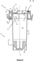
- the sampling device of figure 4 can be seen in cross section along B-B.
- the receptacle 22 has a side wall portion 36 and a bottom wall portion 38 at a first end 22' of the receptacle 22 that together define an inner material receiving space 40 and terminates with a receptacle opening 42 at a second end 22' opposite the first end 22', here provided as an open top opposing the bottom wall portion 36.
- the longitudinal axis A passes centrally in a direction end to end 22',22" between the bottom wall portion 38 and the open top 42.
- the entire top of the sample container 10' is, in the present embodiment, sealed by a seal 44 such as by a polymer/plastic layer which can, in some cases act to prevent contamination thereof.
- the seal 44 then provides a liquid impermeable barrier covering the opening into the container 20 and the bore 12 while allowing liquid access from the upper side of the sample receiving portion 14 and to the sample well 18.
- the seal 44 may cover only the opening of the container in order to prevent loss, such as by evaporation, of any contents thereof which, in use, are intended to be reacted with sample from the sample well 18 and to prevent liquid in the sample well 18 entering the container 20.
- the bore 12 may in some embodiments also be similarly sealed in order to prevent ingress of unwanted material.
- seal 44 may be designed to selectively cover only any one or more openings provided in the sample container.
- the seal 44 at least above the opening into the container 20 (or other opening(s) where access from external the sample container 10' is desired) is made penetrable, for example by a pipette, such as by having a sufficiently small layer thickness.
- the sample container (10' say) closes the open top 42.
- the body 8 of the sample container 10' houses the sample well 18; container 20 and the oblong channel 21 in which is located the oblong sampling element 23 and is here formed as an annulus (thick ring) to provide a central through hole which acts as the sample receiving portion 14.
Landscapes
- Health & Medical Sciences (AREA)
- Chemical & Material Sciences (AREA)
- Clinical Laboratory Science (AREA)
- Chemical Kinetics & Catalysis (AREA)
- Analytical Chemistry (AREA)
- General Health & Medical Sciences (AREA)
- Hematology (AREA)
- Sampling And Sample Adjustment (AREA)
Claims (10)
- Probenahmevorrichtung (24), umfassend ein Aufnahmegefäß (22), das einen inneren Materialaufnahmeraum (40), der durch einen Seitenwandabschnitt (36) und einen Bodenwandabschnitt (38) an einem ersten Ende (22') des Aufnahmegefäßes (22) definiert ist, und eine Aufnahmegefäßöffnung (42) an einem zweiten Ende (22") des Aufnahmegefäßes (22) gegenüber dem ersten Ende (22') aufweist; und einen Probenbehälter (10; 10'; 10"), der angepasst ist, um die Aufnahmegefäßöffnung (42) zu überdecken, wenn er sich mit dem Aufnahmegefäß (22) zusammen befindet, wobei der Probenbehälter (10; 10'; 10") einschließt:- einen zentralen Probenaufnahmeabschnitt (14), der sich, wenn sich der Probenbehälter (10; 10'; 10") mit dem Aufnahmegefäß (22) zusammen befindet, in Flüssigkeitsverbindung mit dem inneren Materialaufnahmeraum (40) befindet,- eine Probenvertiefung (18), die radial außerhalb des Probenaufnahmeabschnitts (14) in einer Richtung senkrecht zu einer Längsachse (A) positioniert ist, die durch den Bodenwandabschnitt (38) und die Aufnahmegefäßöffnung (42) hindurch verläuft, wobei die Probenvertiefung (18) eine Vertiefungsöffnung aufweist,- einen Flüssigkeitsdurchgang (16), der sich von einer ersten Öffnung in den Probenaufnahmeabschnitt (14) zu einer zweiten Öffnung in die Vertiefungsöffnung erstreckt;- einen Behälter (20), der eine Behälteröffnung aufweist; und- eine flüssigkeitsundurchlässige Barriere (8'; 44), die angepasst ist, um zu verhindern, dass Flüssigkeit aus dem zentralen Probenaufnahmeabschnitt (14) in die Behälteröffnung eindringt; dadurch gekennzeichnet, dassder Probenaufnahmeabschnitt (14) an einer ersten Längsposition, die auf die Längsachse (A) projiziert wird, die Vertiefungsöffnung an einer zweiten Längsposition, die auf die Längsachse (A) projiziert wird, und die Behälteröffnung an einer dritten Längsposition positioniert ist, die auf die Längsachse (A) projiziert wird, wobei die dritte Position in einer Richtung entlang der Längsachse (A) von dem Bodenwandabschnitt (38) zu der Aufnahmegefäßöffnung (42) über der ersten und der zweiten Position liegt.
- Probenahmevorrichtung (24) nach Anspruch 1,
dadurch gekennzeichnet, dass:- die Vertiefungsöffnung, wenn sie auf eine Ebene senkrecht zu der Achse (A) projiziert wird, zwischen einem ersten, minimalen Abstand zu der Achse und einem zweiten, maximalen Abstand zu der Achse (A) positioniert ist, und- die Behälteröffnung in der Ebene zwischen einem dritten, minimalen Abstand (r-min) zu der Achse (A) und einem vierten, maximalen Abstand (r-max) zu der Achse (A) positioniert ist, wobei das Intervall, das durch den ersten und den zweiten Abstand definiert ist, eine Überlappung mit dem Intervall aufweist, das durch den dritten (r-min) und vierten (r-max) Abstand definiert ist. - Probenahmevorrichtung (24) nach einem der vorstehenden Ansprüche, wobei sich die zweite Öffnung in einen oberen Abschnitt der Probenvertiefung (18) öffnet.
- Probenahmevorrichtung (24) nach einem der vorstehenden Ansprüche, ferner umfassend ein zuvor bestimmtes Material in dem Behälter (20).
- Probenahmevorrichtung (24) nach einem der vorstehenden Ansprüche, wobei die flüssigkeitsundurchlässige Barriere aus einem Dichtungselement (44) besteht, das mindestens den Behälter (20) abdichtet.
- Probenahmevorrichtung (24) nach einem der vorstehenden Ansprüche, wobei der Probenbehälter (10'; 10") ferner einen länglichen Kanal (21; 21') und einen darin untergebrachten Messstab (23) umfasst.
- Probenahmevorrichtung (24) nach Anspruch 6, wobei der Probenbehälter (10; 10'; 10") ferner einen zweiten Behälter (20') umfasst, in den sich der längliche Kanal (21; 21') öffnet.
- System zum Handhaben einer Probe, das System umfassend:- eine Probenahmevorrichtung (24) nach einem der Ansprüche 1 bis 7;- einen Rotator zum Rotieren der Probenahmevorrichtung (24) um die Längsachse (A) herum; und- eine Dosiereinrichtung (30), die angepasst ist, um eine Flüssigkeitsmenge zwischen dem Behälter (20) und der Probenvertiefung (18) zu übertragen.
- System nach Anspruch 8, wobei die Dosiereinrichtung (30) eine Pipette (34) umfasst, die für eine Verschiebung entlang einer Richtung parallel zu der Längsachse (A) angepasst ist.
- Verfahren zum Handhaben einer Probe, das Verfahren umfassend:- Zuführen eines Materials zu dem Aufnahmegefäß (22) einer Probenentnahmevorrichtung (24) nach einem der Ansprüche 1 bis 7,- Rotieren der Probenentnahmevorrichtung (24) um die Längsachse (A) herum, damit sich ein Abschnitt des Materials aus dem Aufnahmegefäß (22) über den Flüssigkeitsdurchgang (16) in die Probenvertiefung (18) bewegt, um eine Probe auszubilden, und- Bedienen einer Dosiereinrichtung (30), um einen Abschnitt der Probe aus der Probenvertiefung (18) in den Behälter (20) zu übertragen.
Applications Claiming Priority (2)
| Application Number | Priority Date | Filing Date | Title |
|---|---|---|---|
| DKPA201800617 | 2018-09-21 | ||
| PCT/IB2019/056707 WO2020058781A1 (en) | 2018-09-21 | 2019-08-07 | A sampling device, a system comprising the sampling device and a method |
Publications (3)
| Publication Number | Publication Date |
|---|---|
| EP3852926A1 EP3852926A1 (de) | 2021-07-28 |
| EP3852926C0 EP3852926C0 (de) | 2024-07-31 |
| EP3852926B1 true EP3852926B1 (de) | 2024-07-31 |
Family
ID=68072869
Family Applications (1)
| Application Number | Title | Priority Date | Filing Date |
|---|---|---|---|
| EP19779118.9A Active EP3852926B1 (de) | 2018-09-21 | 2019-08-07 | Probenahmevorrichtung, system mit der probenahmevorrichtung und verfahren |
Country Status (9)
| Country | Link |
|---|---|
| US (1) | US11918997B2 (de) |
| EP (1) | EP3852926B1 (de) |
| CN (1) | CN112543677B (de) |
| AR (1) | AR116469A1 (de) |
| AU (1) | AU2019341671B2 (de) |
| CA (1) | CA3100506A1 (de) |
| ES (1) | ES2989206T3 (de) |
| UA (1) | UA128619C2 (de) |
| WO (1) | WO2020058781A1 (de) |
Citations (3)
| Publication number | Priority date | Publication date | Assignee | Title |
|---|---|---|---|---|
| US5501837A (en) * | 1994-07-15 | 1996-03-26 | Sayles; Philip W. | One-step test device |
| US6514461B1 (en) * | 1997-02-14 | 2003-02-04 | Escreen, Inc. | System for automatically testing a fluid specimen |
| US20070140915A1 (en) * | 2005-12-12 | 2007-06-21 | Cytyc Corporation | Method and Apparatus for Obtaining Aliquot from Liquid-Based Cytological Sample |
Family Cites Families (16)
| Publication number | Priority date | Publication date | Assignee | Title |
|---|---|---|---|---|
| US4933291A (en) | 1986-12-22 | 1990-06-12 | Eastman Kodak Company | Centrifugable pipette tip and pipette therefor |
| US5244635A (en) | 1992-06-19 | 1993-09-14 | Cirrus Diagnostics, Inc. | Centrifuge vessel with coaxial waste chamber having cap to prevent waste fluid transfer from the chamber into the vessel |
| US6342183B1 (en) | 1997-02-14 | 2002-01-29 | Escreen | System for collecting and locally analyzing a fluid specimen |
| US7384602B2 (en) * | 2002-05-08 | 2008-06-10 | Hitachi High-Technologies Corporation | Chemical analysis apparatus and genetic diagnostic apparatus |
| US20040166551A1 (en) * | 2003-02-24 | 2004-08-26 | John Moulds | Detection of agglutination of assays |
| CN101194155B (zh) * | 2005-04-09 | 2012-07-18 | 贝林格尔英格海姆米克罗帕茨有限责任公司 | 用于测试样品液的装置和方法 |
| AT502549B1 (de) * | 2005-10-07 | 2007-06-15 | Anagnostics Bioanalysis Gmbh | Vorrichtung zur analyse von flüssigen proben |
| CN101971035B (zh) * | 2008-01-21 | 2013-10-16 | 三星电子株式会社 | 薄膜分层离心装置及使用其的分析方法 |
| US8337711B2 (en) | 2008-02-29 | 2012-12-25 | Biomet Biologics, Llc | System and process for separating a material |
| WO2010026911A1 (ja) | 2008-09-08 | 2010-03-11 | アークレイ株式会社 | 試料採取用具およびそれに用いる収容容器 |
| DE102011077134A1 (de) * | 2011-06-07 | 2012-12-13 | Robert Bosch Gmbh | Kartusche, Zentrifuge sowie Verfahren zum Mischen einer ersten und zweiten Komponente |
| DE102013200352A1 (de) * | 2013-01-14 | 2014-07-17 | Robert Bosch Gmbh | Kartusche, Zentrifuge für diese Kartusche sowie Verfahren |
| EP2942104A1 (de) * | 2014-05-08 | 2015-11-11 | Radisens Diagnostics Ltd. | Probenapplikator für Point-of-Care-Vorrichtung |
| EP2952258A1 (de) * | 2014-06-06 | 2015-12-09 | Roche Diagnostics GmbH | Drehbare Kartusche zur Analyse einer biologischen Probe |
| US10835897B2 (en) * | 2015-03-16 | 2020-11-17 | Dots Technology Corp. | Portable allergen detection system |
| RU195122U1 (ru) * | 2016-09-20 | 2020-01-15 | ФОСС Аналитикал А/С | Фильтрующее устройство |
-
2019
- 2019-08-07 AU AU2019341671A patent/AU2019341671B2/en active Active
- 2019-08-07 US US17/270,990 patent/US11918997B2/en active Active
- 2019-08-07 UA UAA202007368A patent/UA128619C2/uk unknown
- 2019-08-07 CA CA3100506A patent/CA3100506A1/en active Pending
- 2019-08-07 WO PCT/IB2019/056707 patent/WO2020058781A1/en not_active Ceased
- 2019-08-07 CN CN201980041776.9A patent/CN112543677B/zh active Active
- 2019-08-07 EP EP19779118.9A patent/EP3852926B1/de active Active
- 2019-08-07 ES ES19779118T patent/ES2989206T3/es active Active
- 2019-09-20 AR ARP190102678A patent/AR116469A1/es active IP Right Grant
Patent Citations (3)
| Publication number | Priority date | Publication date | Assignee | Title |
|---|---|---|---|---|
| US5501837A (en) * | 1994-07-15 | 1996-03-26 | Sayles; Philip W. | One-step test device |
| US6514461B1 (en) * | 1997-02-14 | 2003-02-04 | Escreen, Inc. | System for automatically testing a fluid specimen |
| US20070140915A1 (en) * | 2005-12-12 | 2007-06-21 | Cytyc Corporation | Method and Apparatus for Obtaining Aliquot from Liquid-Based Cytological Sample |
Also Published As
| Publication number | Publication date |
|---|---|
| EP3852926C0 (de) | 2024-07-31 |
| AU2019341671B2 (en) | 2024-06-20 |
| AU2019341671A1 (en) | 2020-12-03 |
| AR116469A1 (es) | 2021-05-12 |
| US11918997B2 (en) | 2024-03-05 |
| CN112543677B (zh) | 2023-05-05 |
| ES2989206T3 (es) | 2024-11-25 |
| CA3100506A1 (en) | 2020-03-26 |
| CN112543677A (zh) | 2021-03-23 |
| WO2020058781A1 (en) | 2020-03-26 |
| UA128619C2 (uk) | 2024-09-04 |
| EP3852926A1 (de) | 2021-07-28 |
| US20210213443A1 (en) | 2021-07-15 |
Similar Documents
| Publication | Publication Date | Title |
|---|---|---|
| US6680027B2 (en) | Fluid sample collection and isolation cup | |
| IE851105L (en) | Sample processor cards for centrifuge. | |
| CZ292583B6 (cs) | Zařízení pro smísení tekutiny s kapalinou | |
| JP2022526588A (ja) | 液体試料の採取および取り扱い装置、方法、並びに物質 | |
| CA2625430C (en) | Liquid sample collection and transport system | |
| MX2009000321A (es) | Dispositivo mecanico para mezclar una muestra de fluido con una solucion de tratamiento. | |
| CA2806380C (en) | Closure with septum strip | |
| EP3852926B1 (de) | Probenahmevorrichtung, system mit der probenahmevorrichtung und verfahren | |
| EP2394167B1 (de) | Probenahme-, verdünnungs- und analysevorrichtung für an oberflächen abgeschiedene partikel und stoffe | |
| EP3853608B1 (de) | Lateral-flow-testvorrichtung und analysator | |
| US9387474B2 (en) | Apparatus for analyzing a test liquid | |
| RU2791727C2 (ru) | Устройство для отбора образца, система, содержащая устройство для отбора образца, и способ | |
| US6802642B2 (en) | Method for mixing liquid in a container and the container for carrying out the method | |
| US11529286B2 (en) | Plasma storage apparatus | |
| KR20250050998A (ko) | 이종 물질 혼합 키트 |
Legal Events
| Date | Code | Title | Description |
|---|---|---|---|
| STAA | Information on the status of an ep patent application or granted ep patent |
Free format text: STATUS: UNKNOWN |
|
| STAA | Information on the status of an ep patent application or granted ep patent |
Free format text: STATUS: THE INTERNATIONAL PUBLICATION HAS BEEN MADE |
|
| PUAI | Public reference made under article 153(3) epc to a published international application that has entered the european phase |
Free format text: ORIGINAL CODE: 0009012 |
|
| STAA | Information on the status of an ep patent application or granted ep patent |
Free format text: STATUS: REQUEST FOR EXAMINATION WAS MADE |
|
| 17P | Request for examination filed |
Effective date: 20210211 |
|
| AK | Designated contracting states |
Kind code of ref document: A1 Designated state(s): AL AT BE BG CH CY CZ DE DK EE ES FI FR GB GR HR HU IE IS IT LI LT LU LV MC MK MT NL NO PL PT RO RS SE SI SK SM TR |
|
| DAV | Request for validation of the european patent (deleted) | ||
| DAX | Request for extension of the european patent (deleted) | ||
| GRAP | Despatch of communication of intention to grant a patent |
Free format text: ORIGINAL CODE: EPIDOSNIGR1 |
|
| STAA | Information on the status of an ep patent application or granted ep patent |
Free format text: STATUS: GRANT OF PATENT IS INTENDED |
|
| INTG | Intention to grant announced |
Effective date: 20240425 |
|
| GRAS | Grant fee paid |
Free format text: ORIGINAL CODE: EPIDOSNIGR3 |
|
| GRAA | (expected) grant |
Free format text: ORIGINAL CODE: 0009210 |
|
| STAA | Information on the status of an ep patent application or granted ep patent |
Free format text: STATUS: THE PATENT HAS BEEN GRANTED |
|
| REG | Reference to a national code |
Ref country code: DE Ref legal event code: R081 Ref document number: 602019056157 Country of ref document: DE Owner name: FOSS ANALYTICAL A/S, DK Free format text: FORMER OWNER: FOSS ANALYTICAL A/S, HILLEROED, DK |
|
| AK | Designated contracting states |
Kind code of ref document: B1 Designated state(s): AL AT BE BG CH CY CZ DE DK EE ES FI FR GB GR HR HU IE IS IT LI LT LU LV MC MK MT NL NO PL PT RO RS SE SI SK SM TR |
|
| REG | Reference to a national code |
Ref country code: CH Ref legal event code: EP Ref country code: GB Ref legal event code: FG4D |
|
| REG | Reference to a national code |
Ref country code: DE Ref legal event code: R096 Ref document number: 602019056157 Country of ref document: DE |
|
| REG | Reference to a national code |
Ref country code: IE Ref legal event code: FG4D |
|
| U01 | Request for unitary effect filed |
Effective date: 20240823 |
|
| U07 | Unitary effect registered |
Designated state(s): AT BE BG DE DK EE FI FR IT LT LU LV MT NL PT RO SE SI Effective date: 20240903 |
|
| U20 | Renewal fee for the european patent with unitary effect paid |
Year of fee payment: 6 Effective date: 20240927 |
|
| REG | Reference to a national code |
Ref country code: ES Ref legal event code: FG2A Ref document number: 2989206 Country of ref document: ES Kind code of ref document: T3 Effective date: 20241125 |
|
| PG25 | Lapsed in a contracting state [announced via postgrant information from national office to epo] |
Ref country code: NO Free format text: LAPSE BECAUSE OF FAILURE TO SUBMIT A TRANSLATION OF THE DESCRIPTION OR TO PAY THE FEE WITHIN THE PRESCRIBED TIME-LIMIT Effective date: 20241031 |
|
| PG25 | Lapsed in a contracting state [announced via postgrant information from national office to epo] |
Ref country code: GR Free format text: LAPSE BECAUSE OF FAILURE TO SUBMIT A TRANSLATION OF THE DESCRIPTION OR TO PAY THE FEE WITHIN THE PRESCRIBED TIME-LIMIT Effective date: 20241101 Ref country code: PL Free format text: LAPSE BECAUSE OF FAILURE TO SUBMIT A TRANSLATION OF THE DESCRIPTION OR TO PAY THE FEE WITHIN THE PRESCRIBED TIME-LIMIT Effective date: 20240731 |
|
| PG25 | Lapsed in a contracting state [announced via postgrant information from national office to epo] |
Ref country code: IS Free format text: LAPSE BECAUSE OF FAILURE TO SUBMIT A TRANSLATION OF THE DESCRIPTION OR TO PAY THE FEE WITHIN THE PRESCRIBED TIME-LIMIT Effective date: 20241130 |
|
| PG25 | Lapsed in a contracting state [announced via postgrant information from national office to epo] |
Ref country code: HR Free format text: LAPSE BECAUSE OF FAILURE TO SUBMIT A TRANSLATION OF THE DESCRIPTION OR TO PAY THE FEE WITHIN THE PRESCRIBED TIME-LIMIT Effective date: 20240731 |
|
| PG25 | Lapsed in a contracting state [announced via postgrant information from national office to epo] |
Ref country code: RS Free format text: LAPSE BECAUSE OF FAILURE TO SUBMIT A TRANSLATION OF THE DESCRIPTION OR TO PAY THE FEE WITHIN THE PRESCRIBED TIME-LIMIT Effective date: 20241031 |
|
| PG25 | Lapsed in a contracting state [announced via postgrant information from national office to epo] |
Ref country code: RS Free format text: LAPSE BECAUSE OF FAILURE TO SUBMIT A TRANSLATION OF THE DESCRIPTION OR TO PAY THE FEE WITHIN THE PRESCRIBED TIME-LIMIT Effective date: 20241031 Ref country code: PL Free format text: LAPSE BECAUSE OF FAILURE TO SUBMIT A TRANSLATION OF THE DESCRIPTION OR TO PAY THE FEE WITHIN THE PRESCRIBED TIME-LIMIT Effective date: 20240731 Ref country code: NO Free format text: LAPSE BECAUSE OF FAILURE TO SUBMIT A TRANSLATION OF THE DESCRIPTION OR TO PAY THE FEE WITHIN THE PRESCRIBED TIME-LIMIT Effective date: 20241031 Ref country code: IS Free format text: LAPSE BECAUSE OF FAILURE TO SUBMIT A TRANSLATION OF THE DESCRIPTION OR TO PAY THE FEE WITHIN THE PRESCRIBED TIME-LIMIT Effective date: 20241130 Ref country code: HR Free format text: LAPSE BECAUSE OF FAILURE TO SUBMIT A TRANSLATION OF THE DESCRIPTION OR TO PAY THE FEE WITHIN THE PRESCRIBED TIME-LIMIT Effective date: 20240731 Ref country code: GR Free format text: LAPSE BECAUSE OF FAILURE TO SUBMIT A TRANSLATION OF THE DESCRIPTION OR TO PAY THE FEE WITHIN THE PRESCRIBED TIME-LIMIT Effective date: 20241101 |
|
| REG | Reference to a national code |
Ref country code: CH Ref legal event code: PL |
|
| PG25 | Lapsed in a contracting state [announced via postgrant information from national office to epo] |
Ref country code: SM Free format text: LAPSE BECAUSE OF FAILURE TO SUBMIT A TRANSLATION OF THE DESCRIPTION OR TO PAY THE FEE WITHIN THE PRESCRIBED TIME-LIMIT Effective date: 20240731 |
|
| PG25 | Lapsed in a contracting state [announced via postgrant information from national office to epo] |
Ref country code: MC Free format text: LAPSE BECAUSE OF FAILURE TO SUBMIT A TRANSLATION OF THE DESCRIPTION OR TO PAY THE FEE WITHIN THE PRESCRIBED TIME-LIMIT Effective date: 20240731 Ref country code: CH Free format text: LAPSE BECAUSE OF NON-PAYMENT OF DUE FEES Effective date: 20240831 |
|
| PG25 | Lapsed in a contracting state [announced via postgrant information from national office to epo] |
Ref country code: CZ Free format text: LAPSE BECAUSE OF FAILURE TO SUBMIT A TRANSLATION OF THE DESCRIPTION OR TO PAY THE FEE WITHIN THE PRESCRIBED TIME-LIMIT Effective date: 20240731 |
|
| PG25 | Lapsed in a contracting state [announced via postgrant information from national office to epo] |
Ref country code: SK Free format text: LAPSE BECAUSE OF FAILURE TO SUBMIT A TRANSLATION OF THE DESCRIPTION OR TO PAY THE FEE WITHIN THE PRESCRIBED TIME-LIMIT Effective date: 20240731 |
|
| PLBE | No opposition filed within time limit |
Free format text: ORIGINAL CODE: 0009261 |
|
| STAA | Information on the status of an ep patent application or granted ep patent |
Free format text: STATUS: NO OPPOSITION FILED WITHIN TIME LIMIT |
|
| 26N | No opposition filed |
Effective date: 20250501 |
|
| PG25 | Lapsed in a contracting state [announced via postgrant information from national office to epo] |
Ref country code: IE Free format text: LAPSE BECAUSE OF NON-PAYMENT OF DUE FEES Effective date: 20240807 |
|
| U20 | Renewal fee for the european patent with unitary effect paid |
Year of fee payment: 7 Effective date: 20250827 |
|
| PGFP | Annual fee paid to national office [announced via postgrant information from national office to epo] |
Ref country code: ES Payment date: 20250901 Year of fee payment: 7 |
|
| PGFP | Annual fee paid to national office [announced via postgrant information from national office to epo] |
Ref country code: GB Payment date: 20250827 Year of fee payment: 7 |
|
| PG25 | Lapsed in a contracting state [announced via postgrant information from national office to epo] |
Ref country code: CY Free format text: LAPSE BECAUSE OF FAILURE TO SUBMIT A TRANSLATION OF THE DESCRIPTION OR TO PAY THE FEE WITHIN THE PRESCRIBED TIME-LIMIT; INVALID AB INITIO Effective date: 20190807 |