EP3852567B1 - Modulares einlagensystem für schuhsohlen - Google Patents
Modulares einlagensystem für schuhsohlen Download PDFInfo
- Publication number
- EP3852567B1 EP3852567B1 EP19813725.9A EP19813725A EP3852567B1 EP 3852567 B1 EP3852567 B1 EP 3852567B1 EP 19813725 A EP19813725 A EP 19813725A EP 3852567 B1 EP3852567 B1 EP 3852567B1
- Authority
- EP
- European Patent Office
- Prior art keywords
- durometer
- midsole
- inserts
- vertical
- sole
- Prior art date
- Legal status (The legal status is an assumption and is not a legal conclusion. Google has not performed a legal analysis and makes no representation as to the accuracy of the status listed.)
- Active
Links
Images


Classifications
-
- A—HUMAN NECESSITIES
- A43—FOOTWEAR
- A43B—CHARACTERISTIC FEATURES OF FOOTWEAR; PARTS OF FOOTWEAR
- A43B13/00—Soles; Sole-and-heel integral units
- A43B13/02—Soles; Sole-and-heel integral units characterised by the material
- A43B13/12—Soles with several layers of different materials
- A43B13/125—Soles with several layers of different materials characterised by the midsole or middle layer
-
- A—HUMAN NECESSITIES
- A43—FOOTWEAR
- A43B—CHARACTERISTIC FEATURES OF FOOTWEAR; PARTS OF FOOTWEAR
- A43B13/00—Soles; Sole-and-heel integral units
- A43B13/14—Soles; Sole-and-heel integral units characterised by the constructive form
- A43B13/18—Resilient soles
- A43B13/181—Resiliency achieved by the structure of the sole
- A43B13/186—Differential cushioning region, e.g. cushioning located under the ball of the foot
-
- A—HUMAN NECESSITIES
- A43—FOOTWEAR
- A43B—CHARACTERISTIC FEATURES OF FOOTWEAR; PARTS OF FOOTWEAR
- A43B13/00—Soles; Sole-and-heel integral units
- A43B13/14—Soles; Sole-and-heel integral units characterised by the constructive form
- A43B13/18—Resilient soles
- A43B13/187—Resiliency achieved by the features of the material, e.g. foam, non liquid materials
- A43B13/188—Differential cushioning regions
-
- A—HUMAN NECESSITIES
- A43—FOOTWEAR
- A43B—CHARACTERISTIC FEATURES OF FOOTWEAR; PARTS OF FOOTWEAR
- A43B7/00—Footwear with health or hygienic arrangements
- A43B7/14—Footwear with health or hygienic arrangements with foot-supporting parts
- A43B7/1405—Footwear with health or hygienic arrangements with foot-supporting parts with pads or holes on one or more locations, or having an anatomical or curved form
- A43B7/1455—Footwear with health or hygienic arrangements with foot-supporting parts with pads or holes on one or more locations, or having an anatomical or curved form with special properties
- A43B7/1464—Footwear with health or hygienic arrangements with foot-supporting parts with pads or holes on one or more locations, or having an anatomical or curved form with special properties with adjustable pads to allow custom fit
-
- A—HUMAN NECESSITIES
- A43—FOOTWEAR
- A43B—CHARACTERISTIC FEATURES OF FOOTWEAR; PARTS OF FOOTWEAR
- A43B7/00—Footwear with health or hygienic arrangements
- A43B7/14—Footwear with health or hygienic arrangements with foot-supporting parts
- A43B7/1405—Footwear with health or hygienic arrangements with foot-supporting parts with pads or holes on one or more locations, or having an anatomical or curved form
- A43B7/1475—Footwear with health or hygienic arrangements with foot-supporting parts with pads or holes on one or more locations, or having an anatomical or curved form characterised by the type of support
- A43B7/148—Recesses or holes filled with supports or pads
-
- A—HUMAN NECESSITIES
- A43—FOOTWEAR
- A43B—CHARACTERISTIC FEATURES OF FOOTWEAR; PARTS OF FOOTWEAR
- A43B7/00—Footwear with health or hygienic arrangements
- A43B7/14—Footwear with health or hygienic arrangements with foot-supporting parts
- A43B7/1405—Footwear with health or hygienic arrangements with foot-supporting parts with pads or holes on one or more locations, or having an anatomical or curved form
- A43B7/1475—Footwear with health or hygienic arrangements with foot-supporting parts with pads or holes on one or more locations, or having an anatomical or curved form characterised by the type of support
- A43B7/149—Pads, e.g. protruding on the foot-facing surface
-
- A—HUMAN NECESSITIES
- A43—FOOTWEAR
- A43B—CHARACTERISTIC FEATURES OF FOOTWEAR; PARTS OF FOOTWEAR
- A43B7/00—Footwear with health or hygienic arrangements
- A43B7/14—Footwear with health or hygienic arrangements with foot-supporting parts
- A43B7/24—Insertions or other supports preventing the foot canting to one side , preventing supination or pronation
Definitions
- the present invention relates to soles for articles of footwear, in particular footwear for correcting, supporting or accommodating the gait of the wearer.
- shoe soles can be manufactured such that the degree of support for the foot differs between different regions of the sole.
- the material of the heel region for example, which experiences the greatest impact forces, is often manufactured to provide greatest impact cushioning effect.
- the desired variation in support may be achieved for example by varying mechanical properties of the material of the sole, such as the shape, thickness, density, hardness and flexural characteristics.
- the sole may be manufactured so as to provide optimum support for the typical wearer's feet. Since gait characteristics vary significantly from person to person, footwear manufacturers design the soles of their products to cater for a broad range of gait types, based around a putative norm. Soles may also be configured to suit different types of use. For example, soles may be configured for sprinting, long-distance running, playing particular sports such as golf or tennis or cross-country skiing, or for casual wear. Running shoes require different sole configurations for different distances, and for different types of terrain.
- the wearer is therefore obliged either to settle for a sole which will cover a wide range of uses, but will not be well configured for any of those uses, or he may purchase different footwear for different uses; different shoes for road-running and for cross-country running, for example, or different shoes for different distances.
- Such insoles may incorporate regions of different support, which are arranged to suit the particular use or gait-type.
- the hardness of the regions may be customised by exchanging portions of the orthotic, for example.
- Such a customisable orthotic is known from EP2383952 , in which a shaped piece of the orthotic can be exchanged for a similarly-shaped piece having a different hardness.
- the orthotic described in this document thus provides a limited customizability of the support which is provided by the insole.
- WO2016092353 from the same inventors as the present invention, describes a sole customising system in which hard inserts are located in cavities in the midsole.
- the application does not address the problem of ensuring constant and accurate sensory-motoric stimulus (see below), but nevertheless proposes an arrangement which could potentially offer a solution in that the inserts can be inserted into the cavities from the top, so that the cavity bottoms are closed by the outsole.
- EP1352579 describes a midsole comprising regions of different hardnesses, so that the midsole can be customised for a particular wearer.
- the assembled portions of the midsole may be formed into a continuous moulding, in which case the customised sole is no longer customisable.
- the assembled portions can remain as discrete components of the sole, in which case the mechanical integrity of the sole as a whole is greatly reduced.
- DE20320091 describes an adaptable insert which affords a limited customizability of the support provided at a particular region of the sole.
- the insert is introduced from the medial side of the sole (ie left-hand side of a right shoe or right-hand side of a left shoe) or the lateral side of the sole (ie right-hand side of a right shoe or left-hand side of a left shoe), and is held in place using a clip.
- the insert also includes vertical hexagonal-shaped holes into which can be inserted hexagonal pegs of a particular hardness.
- the effective hardness of the insert can be varied by inserting pegs which are harder than the material of the insert, which gives the wearer some control over the degree of support provided at that particular region of the sole when the insert is located in position.
- the midsole is provided with a wide horizontal cavity, open to one side, into which the insert can be pushed.
- the presence of a wide cavity reduces the overall mechanical integrity of the sole, even with the insert in place, and provides a path for water and dirt to enter the sole, and to work their way deep within the sole.
- the presence of the midsole material above and below the cavity means that the effectiveness of the lateral insert is reduced, in that the amount of vertical support it provides is reduced, and the total amount of vertical support provided may the sole in the region of the insert can be less accurately defined.
- the material of the midsole above and below the cavity, and the material of the insert element surrounding the pegs will lose elasticity and resilience due to the repeated compression during the gait cycle.
- Such insert elements are typically positioned in regions of the sole where greater support is required, which means that the repeated compression, and the consequent crushing of the insert material and the midsole material above and below the insert, will be particularly susceptible to degradation, and thereby shorten the wearable life of the shoe.
- the invention described in this application seeks to overcome at least some of the above and other disadvantages inherent in the prior art.
- the invention aims to provide a customisable article of footwear according to claim 1.
- a support customising system is described below for the sole of a shoe or other article of footwear.
- the sole comprises a relatively soft, resilient midsole and (optionally) a harder outsole.
- Insert elements of various hardnesses are provided for inserting into vertical cavities in the midsole.
- a precisely-tunable pronation control effect on the wearer's gait can be effected.
- First-order, second-order and third-order pronation control effects are described.
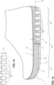
- FIG. 1a depicts a schematic cross-section of a shoe with a sole 1 comprising an outsole 4, aFF midsole 3, bonded to the outsole 4, and a liner or insole 6 laid on the upper surface 7 of the midsole 3.
- the midsole 3 may be made of a resilient material, for example an elastomer such as ethyl vinyl acetate (EVA) or other suitable material.
- EVA ethyl vinyl acetate
- the outsole 4 may for example be constructed from a hard, resilient elastomeric material such as rubber/polyurethane, and may have a hardness which is greater than that of the midsole 3, at least at the ground-facing surface of the outsole 4.
- the midsole 3 and outsole 4 may comprise the same or similar materials, or may be contiguous, homogenous regions of the same moulded shape.
- the liner or insole 6 may be of relatively thin and/or softer material and serves to provide a comfortable surface for the sole of the wearer's foot. The liner or insole 6 may be removed to expose the upper surface 7 of the midsole 3.
- the example sole 1 illustrated in figure 1a is provided with a plurality (six are shown) of vertical cavities 2, each of which opens out through the outsole 4 and extends up towards the upper surface 7 of the midsole 3 along a vertical axis 8.
- the midsole 3, apart from the holes (cavities 2) which are formed in it, may be constructed of continuous material, in order to ensure the mechanical integrity of the sole as a whole.
- the vertical direction is understood in this text to be the vertical direction when the shoe is standing flat on level ground.
- the vertical axis 8 is thus substantially orthogonal to the general plane 9 of the sole 1, which is taken to be generally parallel to the upper, foot-facing surface 7 of the midsole 3 and/or to the lower surface of the outsole 4, at least in the heel and/or midfoot regions 13, 14 of the sole 1.
- the sole 1 illustrated in figure 1a has parallel upper and lower surfaces for clarity.
- the heel area of the sole may be thicker than the forefoot area ('positive drop'), or vice versa ('negative drop'), and/or the mid-foot zone may be thicker than both the heel and forefoot regions, for example.
- Figure 1b shows a set of inserts or plugs 5, also referred to in this description as support adjustment inserts or proprioception-enhancing inserts, which are designed for insertion into the cavities 2 in the midsole 3.
- the inserts 5 may be inserted into the cavities 2 through openings in the outsole 4. Inserting the inserts from below has the advantage that the insertion openings are more readily accessible than if they are inserted from above. However, as discussed below, inserting the inserts through the outsole 4 renders the inserts liable to damage by over-compression (for example if the wearer steps on a stone) or by incursion of dirt or water.
- the inserts 5 may also be made of an elastomeric material, for example, and they may have different hardnesses from the midsole 3 and/or from one another. Some of the inserts 5 may have substantially the same hardness as the material of the midsole 3, in order to provide a null support adjustment at a particular cavity 2. It is also possible to provide inserts 5 with lower hardnesses than the midsole 3; this may for example be useful for providing a negative support adjustment in a particular region of the sole 1 by reducing the average hardness of the region by inserting one or more inserts 5 which are softer than the material of the surrounding midsole 3.
- the hardnesses of the inserts 5 may be selected from a set of predetermined hardnesses.
- a pair of shoes having soles such as that illustrated in figures 1a may be purchased with a set of inserts 5 similar to those shown in figure 1b , with multiple alternative inserts of different hardnesses available for insertion into each cavity, and with each insert having one of a predetermined selection of hardnesses.
- the midsole 3 may have a hardness in the range 30 to 70 Shore, or 45 to 60 Shore, for example, and the supplied set of inserts 5 may include some inserts having a hardness of 50 Shore, some of 60 Shore, some of 70 Shore, some of 80, 90 or even 100 Shore, for example. Different inserts 5 of different hardnesses may then be fitted into the cavities 2 provided, so as to achieve the desired local support hardness at each cavity location and collectively in each region of the sole 1 provided with cavities 2. If the midsole has a first durometer, then the set of inserts from which inserts can be selected for insertion into the cavities may include inserts, each of which may have one of a predetermined plurality of durometers.
- the plurality of durometers may include durometers which differ from each other by between 5 and 20 Shore, including a durometer which is greater than the first durometer by between 5 and 40 Shore. As will be discussed below, the plurality of durometers may include a durometer which is the same as the first durometer and/or one or more durometers which are less than the first durometer.
- the first durometer of the midsole 3 may be constant for all regions of the midsole 3, or it may vary between regions of the midsole 3. In the latter case, the first durometer may either be taken to be an average durometer of the midsole 3 or a local durometer of a particular region of the midsole 3.
- the inserts 5 which are harder than the surrounding midsole material serve to transfer a force from between the ground and the wearer's foot which is greater than that transferred by the surrounding midsole material.
- Each of these harder inserts thereby provides increased support for the wearer's foot at the location in the sole at which it is inserted.
- the inserts 5 each have one of a predetermined set of hardnesses, at least in the vertical direction, and because they extend along substantially the whole vertical depth 11 of the sole 1, or at least substantially the whole depth 11 of the midsole 3, the net vertical hardness of the sole 1 at the location of each cavity 2 is determined exclusively, or in a great majority, by the hardness of the particular insert 5.
- the hardness of the outsole 4, if it is different from the hardness of the insert 5, may also contribute an effect to the net vertical hardness of the sole 1 at that location, but the contribution may be small, particularly if the outsole 4 is thin and/or the hardness difference between the outsole 4 and the insert 5 is small.
- the contribution of the insole 6 or any minor part of the midsole which extends above or below the insert 5 when the insert 5 is inserted will also have only a small effect on the net vertical hardness of the sole 1 at the particular cavity.
- the term net vertical hardness is used here to indicate a measure of the compressibility and resilience of the sole in an approximately vertical direction (ie as measured along the vertical axis 8).
- the net vertical hardness at a particular location may be represented or measured for example using the 25% compressive strength measurement at the location. This measure may be used, for example, where the inserts are 50% or less than the thickness of the sole at the location.
- An insert may be considered to have a proprioceptive effect if the durometer of the insert is such that the 25% compressive strength of the sole at its location is at least 50% greater than the 25% compressive strength of the surrounding sole adjacent to the insert/cavity.
- the presence or absence of a proprioceptive insert may be determined using a test as follows:
- the pointwise compressive strength of the sole at a particular location can be measured by vertically compressing the sole between a small upper plate, having a predetermined area of for example between 2 and 4 cm2, placed directly over the region of the sole being measured, and a larger lower plate, placed directly beneath the region of the sole being measured and beneath the lower surface of the lower surface of the sole (ie the lower surface of the insert and the outsole if present).
- the plates may be moved together so as to compress the sole vertically to a compression of 25% of the thickness of the sole (reduce the distance between upper and lower plates by 25%).
- the pressure which must be applied to the upper plate to achieve the 25% compression can be taken as a measure of the compressive strength of the sole at that location.
- the 25% compressive strength of the sole with the insert is at least 50% greater than the 25% compressive strength of the adjacent sole material alone, then a significant proprioceptive effect is said to be present.
- the propioceptive effect may be considered to be present when the durometer of the insert is at least 5 Shore A greater, or optionally 10 Shore A greater, than the durometer of the surrrounding midsole.
- the vertical cavities 2 and the inserts 5 shown in the example of figures 1a and 1b have substantially parallel vertical side-walls.
- the cavities 2 may thus have a horizontal cross-section which is substantially constant along their length 11, for example, or they may have a tapering cross-section, any other shape which allows them to be fitted into the cavities 2 and/or subsequently removed for exchange.
- the horizontal cross-section of the cavities 2 and inserts 5 may be of any regular shape, such as circular, oval, ovoid, hexagonal, triangular, square or rectangular, or it may have have an irregular shape.
- the inserts 5 and cavities 2 are advantageously dimensioned such that it is possible to fit two or more cavities/inserts into a particular gait control region of the sole 1, as will be discussed below.
- the cavities and inserts 5 may be formed with a horizontal cross-section which has a largest transverse dimension of between 5mm and 50mm across, for example, or preferably between 10mm and 30mm.
- a pronation control zone in the forefoot area 12 of the sole 1 may incorporate multiple (eg three to ten inserts), for example, each with a hardness suitable for the pronation control requirement of the wearer.
- the hardnesses of the three to ten inserts 5 may be the same, or they may be graded. For example, the hardnesses of the inserts may be increased from the rear-most insert 5 to the foremost insert 5.
- the discussion above has related primarily to the inserts 5 and cavities 2 of a single shoe.
- the inserts 5 and cavities 2 may similarly be made so that the same inserts 5 can be used in the cavities 2 of either shoe.
- the support customising system may be arranged such that, multiple pairs of shoes can share the same set of support adjustment inserts 5.
- the use of multiple, interchangeable inserts 5 having different hardnesses means that the support provided by the sole 1 can be finely tuned to the needs of the wearer.
- the support may be differently tuned between the left shoe and right shoe, between different regions 12, 13, 14 of one sole 1, or even within the same region of the sole 1.
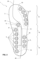
- Figure 2 shows a plan view of a shoe sole 1 similar to the sole 1 shown in figure 1a , and shows in more detail how the support adjustment inserts 5 can be arranged in the midsole 3 to achieve a customised support, for example as an aid to gait correction for the wearer.
- Figure 2 shows the midsole 3 of a left shoe, viewed from below, but it will be understood that the following description applies equally to a corresponding right shoe, although the arrangement of inserts 5 may be different between the left and right shoes.
- the sole 1 comprises a heel region 19, a heel medial region 21, a heel lateral region 22, a forefoot lateral region 23, a metatarsal region 24 and a forefoot medial region 25.
- These regions are merely examples - other regions may be chosen. If there are multiple inserts 5 in each region, as shown, the support offered by the region as a whole can be adjusted precisely by including individual inserts having different durometers - either to give an overall average hardness which is equivalent to an intermediate durometer value between the available values of the available inserts, or to give a graded support across the region.
- the characteristics of the landing portion 19 of the heel region should preferably be the same for left and right shoes.
- the inserts 5 of a particular region, or of multiple regions of the sole may have the same cross-sectional shape, the inserts 5 may be made interchangeable between all cavities 2 of a particular region or between all cavities 2 of the sole. In this case many different configurations of the support offered by the sole can be achieved with a relatively modest number of inserts 5.
- Each insert 5 may be formed as a single contiguous piece of material, or it may be formed from two or more constituent pieces. It may be solid, for example to assure its rigidity, or it may be hollow, for example to cut down on shoe weight and material costs. It may be open at one or both ends, and it may have openings in its side wall(s).
- an ideal gait line 20 also known as the stability axis or "S-line", which indicates approximately how the wearer's foot should pronate during its heel-to-toe contact (gait cycle) with the ground.
- the example regions 19, 21, 22, 23, 24 are identified only approximately, and are used to illustrate how inserts 5 in the various regions can be used for controlling the wearer's gait.
- the multiple cavities 2 may advantageously have the same size and shape, as illustrated in figure 2 .
- the inserts 5 of a particular set even if they have different hardnesses, may also have the same size and shape, so that multiple inserts 5 of different hardnesses can be interchangeably fitted into each cavity 2, and so that a particular insert 5 can be fitted into multiple cavities 2.
- the hind-most heel part 19 of the midsole 3 in figure 2 is shown without any inserts 5 in this example.
- this hind-most region 19 There may be instances when it may be useful to be able to adjust the hardness of this hind-most region 19, but the illustrated example is designed to show how the support adjustment inserts 5 can be used for pronation/supination control, and the hindmost region 19 of the midsole 3 serves primarily to cushion and control the landing impact of the heel on the ground and the initial forward motion of the foot.
- Medial and lateral control regions 21 and 22 can be used to control the amount of pronation during the initial phase of the gait cycle (ie following initial heel impact).
- the hardnesses of the inserts 5 1 of the medial region 21 and the hardnesses of the inserts 5 1 and 5 2 of the medial 21 and lateral 22 control regions it is possible to influence the degree of pronation of the foot around the stability "S-line" 20.
- the use of inserts 5 of graded hardnesses in a particular region permits a second-order control, in which not only the amount of pronation can be controlled, but also the rate of change of pronation with respect to the forward motion of the foot during the sole's contact with the ground when walking or running.
- a first-order pronation control can be obtained by selecting the hardness of the three inserts 5 2 relative to the hardness of midsole 3 and/or of the medial control inserts 5 1 .
- Harder lateral inserts 5 2 will encourage greater pronation, softer lateral inserts 5 2 will promote pronation less.
- by varying the difference between the durometers of the lateral inserts 5 2 it is possible to achieve a second-order control effect.
- the rate of pronation with respect to the foot's forward motion is greater. This means that the pronation occurs during a shorter time, when considered as proportion of the total contact time with the ground.
- the hardness of the inserts 5 2 varies little along the heel to toe direction, then the pronation-enhancing effect with respect to the foot's forward motion will be less. If the foremost lateral insert 5 2 is harder than the rear-most insert 5 2 , then this will act to reduce the rate of pronation.
- the lateral and medial inserts 5 1 and 5 2 can further be used to achieve a third-order control effect, in that inserts can be selected to vary the rate of pronation. If the lateral control region 22 is provided with more cavities and inserts 5 2 , (say five inserts in a line running parallel to the heel-toe axis, for example), then the hardnesses of the five lateral inserts 5 2 can be chosen so as to vary the rate pronation along the heel-to axis.
- the control effects described above in relation to the interchangeable inserts 5z of the lateral region 22 also apply to the other illustrated regions in figure 2 ; the medial control region 21 with its multiple medial control inserts 5 1 , and the forefoot control regions 23 and 25, with their forefoot control inserts 5 3 and 5 5 .
- a single mid-foot control insert 5 4 is illustrated in midfoot control region 24, which may be included in the midfoot /metatarsal region to discourage the wearer's arch from sinking.
- the sole 1 may comprise such a single midfoot insert 24 on its own or in combination with one or more other inserts, as shown in figure 2 , for example.
- the soles can be "tuned" for different uses, or for different wearers, or as the shoes age, or as the wearer's gait changes.
- the following examples illustrate the insert hardnesses which could be chosen for different gait control purposes.
- the examples are based on a sole configuration similar to that shown in figure 2 , and the hardnesses given are relative to an example midsole material of hardness 50 Shore. Where different inserts hardnesses are listed for a particular region, these are listed on the order from rear-most to foremost).
- the sole of figure 2 also shows how a stiffening plate 10 may optionally be included to maintain longitudinal and torsional stiffness of the part of the sole under the arch of the wearer's foot.
- the presence of such a plate can improve the stability of the wearer's foot with respect to the ground surface, and may increase the life of the shoe sole.
- the plate 10 is also visible in figures 12 to 14 .
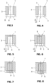
- Figures 3 to 8 illustrate various example arrangements for the cavities 2 and inserts 5, as mentioned above.
- the cavity 2 comprises an opening in the upper surface 7 of the midsole 3, and is closed at its lower end by outsole 4.
- the cavity 2 is shown with an opening above and below.
- Figures 5 to 8 show arrangements in which the cavity 2 is closed at its upper end by a minority portion (eg 10% - 20%) of the thickness of the material of the midsole 3.
- the inserts 5 may be secured in the cavities 2 by any suitable means. If an insert is intended to remain in its cavity permanently, then it may be glued or bonded or welded in place in the cavity 2.
- the insert 5 may even be supplied as a liquid which can be introduced into the cavity 2 and which then sets with a predetermined hardness.
- Figures 5 and 6 show the cavity with and without the insert 5 inserted.
- the insert of this example comprises a body portion 5, which may have a hardness selected to give the desired proprioceptive stimulus pressure to the foot at that location, and an outsole portion 5', which may comprise a similar material to that of the outsole 4.
- the insert may be of a single heterogenous piece of material.
- the lower portion 5' (eg the outsole portion) of the insert 5 may advantageously be wider than the body portion which fits into the cavity 2. This has the following advantages which help to maintain a constant proprioceptive stimulus pressure provided by the insert 5 at the location. Firstly, the broader outer part 5' abuts the lower surface 15 of the midsole element 3. This prevents the insert from being over-compressed and receding into the cavity. It also distributes the load on the insert more evenly, thereby ensuring a constant proprioceptive stimulus effect from the insert as a whole on the wearer's foot at that location. Secondly, the broader outer part 5' covers the region where the sidewall of the insert body is in contact with the sidewall of the cavity.
- the accumulated matter may cause a hardening effect which will alter the proprioceptive pressure at the location and/or erode the material of the midsole 3 or the insert 5, such that the insert may work loose and drop out.
- Figure 8 shows an example variant in which the insert 5 extends downward beyond the outsole 4, thereby increasing the proprioceptive pressure effect at the location. This is made possible, with a reduced risk of the insert being pushed up into the cavity, by the shoulder which abuts the lower surface 15 of the midsole 3 as described above.
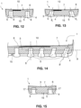
- Figures 9 to 11 show variants in which an optional plate 16 is included over all or some of the inserts 5 in order to delocalise the pressure which occurs between the foot and the individual inserts 5.
- the plate 16 may be hard enough and flexible enough to distribute the pressure without influencing the proprioceptive or sensory-motoric effect of graded or varied hardnesses of the inserts.
- the plate 16 may optionally cover the whole foot-contact area of the sole or even the whole area of the sole.
- the plate 16 may optionally be recessed into the upper surface 7 of the midsole 3 as shown.
- the inserts 5 of figure 9 are shown flush with the lower surface of the outsole 4.
- the inserts 5 of figure 10 extend slightly (1mm to 5mm) proud of the lower surface of the outsole 4, and the inserts 5 of figure 11 are profiled and extend further, thereby further increasing the localised proprioceptive stimulus pressure at the location.
- Figures 12 to 14 show variants in which the cavities and inserts are angled slightly from the vertical, in a transverse direction as in figure 13 and/or in a longitudinal direction as in figure 14 .
- the vertical axes 8, 8 1 , 8 2 , 8' of one or more cavities may be angled slightly outwardly or inwardly in order to enhance the effect of the choice of insert hardness.
- the cavities of the forefoot region may be angled forwards from the vertical in order to increase an acceleration effect at the end of the gait ground contact cycle, thereby enhancing a rolling or rocking in the gait of the wearer. With this configuration it is thus possible to perform a pronation control as discussed above, in addition to enhancing a rolling gait of the wearer.
- the tilt angles mentioned here are preferably less than 30 degrees, or more preferably less than 15 degrees.
- Figure 15 shows an example of an insert retention arrangement.
- the inserts may be retained in the midsole 3 by gluing, bonding, welding, or by form-fit, compression fit or other mechanical fitting.
- the inserts may be glued in position using an adhesive which allows the insert to be released (for example by application of heat) and replaced.
- a retention element such as a peg or pin 17 may be inserted, for example transversely, as shown in figure 15 , to secure the insert 5 in position so that it cannot fall out or work its way out of its cavity 2.
- Inserts 5 may be made so that they can be inserted into the midsole 3 by hand, for example.
- Figures 16 to 27 show various configurations in which the lower (outsole) part 5' of the insert extends laterally outward of the insert body 5.
- the outsole 4 is provided with an opening shaped and dimensioned to accommodate the corresponding lower part 5' of the insert.
- Figure 16 shows a simple insert geometry in which the lower part 5' is flush with the upper and lower surfaces of the outsole 4.
- Figure 17 shows an arrangement in which the upper surface of the lower part 5' is flush with the upper surface of the outsole 4, and the lower surface of the lower part 5' extends proud of the lower surface of the outsole 4.
- the lower surface of the lower part 5' of the insert may be provided with a texture or tread for improved grip.
- Figure 18 shows an arrangement in which the shoulder formed by the upper surface of the lower part 5' abuts a corresponding shoulder formed in the sidewall of the opening in the outsole 4.
- the lower part 5' also extends proud of the outsole 4.
- Figure 19 shows an arrangement in which the lower part 5' abuts the outer surface of the outsole 4.
- Figure 20 shows how the side surfaces of the lower part 5' of the insert may have other profile shapes such as the angled surface shown.
- Figure 21 shows an arrangement in which the lower part 5' of the insert has two shoulders; a first, upper one which may be similar to the abutment arrangement of figure 16 or 17 , for example, and a second, lower shoulder similar to the abutment arrangement of figure 19 .
- Two or more shoulders may be advantageous in that they provide more protection against dirt or water ingress. They also provide more surface area for bonding the insert's lower part 5' to the outsole 4 and/or the midsole 3.
- Figure 22 shows how the upper part of the insert body 5 may be provided with a cavity 12 which may help to retain the insert in the cavity by vacuum suction.
- a cavity 12 which may help to retain the insert in the cavity by vacuum suction.
- air When vertical pressure is exerted on the insert, compressing it slightly, air may be expelled from the cavity 12.
- the pressure is release, the surfaces around the cavity may be drawn together by the resulting pressure differential so as to create a gas-tight seal which prevents air from re-entering the cavity 12.
- the cavity 12 may be deeper than illustrated.
- the hardness of the insert material may be increased so as to maintain the propriocepive (sensory motoric) stimulus effect with the reduced volume of solid insert material.
- Figure 23 shows a two-shoulder arrangement similar to that of figure 21 , in which the lower should is adapted to accommodate bending movement of the outsole 4 by being sufficiently elastic and/or sufficiently well bonded to the outsole 4 that the lower should forms a reliable permanent seal against the ingress of dirt or water.
- Figure 24 shows how the insert may be shaped to be retained in the cavity by mechanical fitting.
- the middle part of the insert body may be slightly wider than the opening through which the insert is inserted, thereby preventing the insert from falling out or riding out of the cavity.
- the inserts 5 may be provided with a positive-fit engagements, which may engage with corresponding recesses in the cavity wall, for example.
- the protrusions may alternatively be arranged in the cavity and the recesses on the insert.
- Figures 24 to 27 show illustrate various further examples of how the inserts may be retained in the cavities by such positive fit or other mechanical interference. Such retention arrangements may be used alone or in combination.
- Figure 25 shows an example in which the insert is retained in the cavity by one or more latch-rings or laching or stepped protrusions 26, 27 in the body and/or outsole part of the insert 5.
- Figure 26 shows an example in which the insert and cavity engage by means of a thread 28, whereby the insert can be screwed into the cavity.
- a slot 29 or other engagement profile may be provided for ease of turning the insert.
- Figure 27 shows how a form fit insert retention may be implemented by angled or tapered surfaces 30.
- a special tool configured to compress the lower part 5' of the insert during insertion, so that it will pass more easily through opening of the outsole 4.
- the inserts may extend up to 5 mm or more proud of the lower surface 15 of the outsole 4, for example, thereby enhancing a sensomotoric (proprioceptive) loading-response of the wearer, in which the foot alters its orientation and movement in response to localised pressure from the inserts and thereby influences the gait of the wearer.
- the inserts 5 have been shown inserted from below into cavities 2 which extend vertically to a point below the upper surface 7 of the midsole 3.
- the inserts and cavities may alternatively be configured to extend right to the upper surface 7 of the midsole 3 or even to protrude above the upper surface 7 so as to create a further enhanced proprioception (sensory-motoric) stimulus in the sole of the wearer's foot.
- the cavities 2 may be provided with a protective liner 18 as shown in figures 28 to 33 .
- the linings 18 of the cavities may be formed as separate pieces and pressed or bonded into the cavities in the midsole 3.
- the linings 18 may be formed (for example moulded) as part of the outsole 4, for example such that the outsole 4 and linings 18 form a contiguous waterproof barrier to prevent water from contacting the midsole material, which may be partially absorbant.
- the cavities formed by the linings may be provided with stepped shoulders, as shown in figures 29, 30, 32 and 33 , for receiving the broader outsole part 5' of the insert inserted into the lining.
- the cavities and inserts are shown vertically oriented in figures 28 to 33 , however, they may be oriented at up to 15°, or up to 30°, from the vertical, for example to provide priorioceptive stimulus along the direction of local maximum force transfer to the wearer's foot.
- the inserts are shown as straight-sided cylinders, but they may be waisted or bulged so as to enhance their retention in the cavity.
- Figure 34 shows a variant in which the insert 5 has a substantially round cross-section (eg spherical or cylindrical).
- the elastomeric outsole 4 and lining 18 may be configured to be elastic that the cavity can be opened wide enough to push the round insert in, and tight enough to retain the round insert once inserted.
- Figures 35 and 36 show how a retaining lug or protrusion 17 can be formed (advantageously contiguous with the material of the outsole 4 and lining 18.
- the outsole can be made sufficiently elastic that the cavity opening can be widened enough to push in the insert (which may or may not have an indent corresponding to the lug 17), such that, when the cavity is allowed to close again, the insert is retained oin position by the additional lateral compression of the lug 17 on the insert body 5 in the cavity 2.
- Cavities in the forefoot and ball regions may advantageously be provided with one or more such lugs, as these regions are susceptible to the greatest flexing during walking or running.
- the lug may advantageously be located on the fowarded side wall of the cavity, so as to retain the insert against flexing from the forefoot region.
- One or more lugs may optionally be provided on the rearward wall, and/or on one or both lateral or medial side walls of a cavity.
- a widened part 19 may be formed at a distal end of the insert 5, and may act as a similar retaining function be exerting lateral force on the side walls of the cavity 2 into which is it inserted.
- the distal widened part 19 may advantageously be made harder than the body of the insert 5, to provide additional 'bite' into the side wall. If the insert is made of an elastomeric foam material, the widening may be achieved by pressing a hot plate against the end surface of the insert, or by cutting the insert from an extruded length of the material using a hot wire or blade. This process has the advantage that it also seals the open cellular end surface against eg water absorption.
Landscapes
- Health & Medical Sciences (AREA)
- Epidemiology (AREA)
- General Health & Medical Sciences (AREA)
- Public Health (AREA)
- Chemical & Material Sciences (AREA)
- Engineering & Computer Science (AREA)
- Materials Engineering (AREA)
- Footwear And Its Accessory, Manufacturing Method And Apparatuses (AREA)
Claims (16)
- Ein Schuhwerk, bestehend aus:eine Sohle (1) mit einem Zwischensohlenteil (3) aus einem ersten Material mit einer ersten Härte, wobei die Zwischensohle (3) eine obere, dem Fuß zugewandte Fläche (7) und eine untere, dem Boden zugewandte Fläche aufweist,einen Laufsohlenteil (4) unterhalb der unteren Fläche (15) der Zwischensohle, wobei die Laufsohle eine zweite Härte aufweist,eine Vielzahl von Hohlräumen (2) in einem ersten Bereich der Zwischensohle (3), wobei sich jeder Hohlraum (2) entlang einer vertikalen Achse (8) im Wesentlichen orthogonal zu der oberen Oberfläche (7) zwischen der unteren und der oberen Oberfläche (7) der Zwischensohle erstreckt, undeine Vielzahl von Stützeinstellelementen (5), von denen jedes im Wesentlichen vollständig in einen der vertikalen Hohlräume (2) eingesetzt ist, um eine vertikale Stützhärte der Sohle (1) an der Stelle des jeweiligen vertikalen Hohlraums (2) einzustellen;wobei jeder vertikale Hohlraum (2) eine Einführungsöffnung in der unteren Fläche zur Aufnahme eines der Stützeinstellelemente (5) umfasst, so dass sich das Einstellelement durch die Laufsohle (4) erstreckt;wobei die Vielzahl von Stützeinstellelementen (5) ein erstes Stützeinstellelement (5) mit einem dritten Durometer und ein zweites Stützeinstellelement (5) mit einem vierten Durometer, der sich von dem dritten Durometer unterscheidet, umfasst, wobei mindestens einer der dritten und vierten Durometer größer ist als der erste Durometer; undwobei jedes der Einstellelemente einen Körperteil zum Einsetzen in den Hohlraum und einen unteren Teil (5') umfasst, der breiter als der Körperteil ist und mit einer Öffnung der Laufsohle (4) verbunden ist oder sich darin befindet.
- Schuhwerk nach Anspruch 1, wobei der zweite Durometer größer ist als der erste Durometer.
- Schuhwerk nach einem der vorhergehenden Ansprüche, wobei sich der vierte Durometer vom dritten Durometer unterscheidet und wobei mindestens einer der dritten und vierten Durometer größer ist als der erste Durometer.
- Schuhwerk nach einem der vorhergehenden Ansprüche, wobei jedes der ersten und zweiten Stützeinstellelemente (5), wenn sie in einen ersten der vertikalen Hohlräume eingesetzt sind, und die Vielzahl der vertikalen Hohlräume (2) im Wesentlichen den gleichen Querschnitt wie der erste vertikale Hohlraum (2) in einer horizontalen Ebene (9) parallel zur oberen (7) und/oder unteren Fläche (15) aufweisen, so dass die ersten und zweiten Stützeinstellelemente (5) austauschbar in den ersten vertikalen Hohlraum (2) durch die Einsetzöffnung des ersten vertikalen Hohlraums eingesetzt werden können.
- Schuhwerk nach einem der vorhergehenden Ansprüche, wobei das erste Stützeinstellelement (5), das zweite Stützeinstellelement (5) und ein erster der mehreren vertikalen Hohlräume (2) im Wesentlichen die gleiche vertikale Länge (11) entlang der vertikalen Achse (8) aufweisen.
- Schuhwerk nach einem der vorhergehenden Ansprüche, wobei das erste und das zweite Stützeinstellelement (5) und die Mehrzahl der vertikalen Hohlräume (2) jeweils einen im Wesentlichen konstanten Querschnitt entlang mindestens eines Großteils ihrer vertikalen Länge (11) aufweisen.
- Schuhwerk nach einem der vorhergehenden Ansprüche, wobei das erste und/oder zweite Stützeinstellelement (5) einen sensomotorischen Stimulusvorsprung aufweist, der so konfiguriert ist, dass er sich bis zur oberen Oberfläche (7) der Zwischensohle (3) erstreckt oder aus dieser herausragt, um einen sensomotorischen Lastreiz für den Fuß eines Trägers an der Stelle des ersten oder zweiten Stützeinstellelements (5) zu erzeugen.
- Schuhwerk nach einem der vorhergehenden Ansprüche, wobei die ersten und/oder zweiten Stützeinstellelemente (5) über die Unterseite (15') der Laufsohle (4) hinausragen.
- Schuhwerk nach einem der vorhergehenden Ansprüche, wobei eine erste Mehrzahl von vertikalen Hohlräumen (2) in einem ersten Gangsteuerungsbereich (21, 22, 23, 24, 25) der Sohle (1) angeordnet ist und eine zweite Mehrzahl der vertikalen Hohlräume (2) in einem zweiten Gangsteuerungsbereich (21, 22, 23, 24, 25) der Sohle (1) angeordnet ist.
- Schuhwerk nach Anspruch 9, wobei die erste und zweite Mehrzahl von vertikalen Hohlräumen (2) und die Mehrzahl von Stützeinstellelementen im Wesentlichen den gleichen Querschnitt aufweisen, so dass die erste Mehrzahl von Stützeinstellelementen (5) passend in die vertikalen Hohlräume (2) der ersten und zweiten Mehrzahl (18, 19) eingesetzt werden kann.
- Schuhwerk nach einem der vorhergehenden Ansprüche, bei dem der dritte Durometer mindestens 5 Shore größer ist als der erste Durometer, bei dem der vierte Durometer mindestens 5 Shore größer ist als der dritte Durometer und/oder bei dem der dritte Durometer kleiner oder gleich dem ersten Durometer ist.
- Schuhwerk nach einem der vorhergehenden Ansprüche, bei dem sich der untere Teil 5' des Verstellelements seitlich im Durchschnitt um mindestens 5 % der Breite des Körperteils erstreckt, der breiter ist als die Öffnung des Hohlraums 2, in den er eingesetzt wird.
- Schuhwerk nach Anspruch 12, bei dem das Unterteil 5' seitlich durchschnittlich mindestens 2 mm oder mindestens 4 mm breiter als die Öffnung und/oder durchschnittlich höchstens 6 mm breiter als der Körperteil ist.
- Schuhwerk nach einem der vorhergehenden Ansprüche, wobei das Material der Zwischensohle ein Polyurethanmaterial umfasst, und/oder wobei das Material des Körperteils eines jeden Verstellelements ein Polyurethanmaterial umfasst, und/oder wobei das Material des Laufsohlenteils (5') eines jeden Verstellelements ein Polyurethanmaterial umfasst.
- Schuhwerk nach einem der vorhergehenden Ansprüche, wobei jedes Einstellelement mit einem Halteelement (17) versehen ist, um einen Körperteil (5') des Einstellelements in der Zwischensohle zu halten.
- Schuhwerk nach einem der vorhergehenden Ansprüche, wobei das Rückhalteelement (17) ein Stift ist, der quer durch die Zwischensohle und den Körperteil einsetzbar ist.
Applications Claiming Priority (2)
| Application Number | Priority Date | Filing Date | Title |
|---|---|---|---|
| CA3018049A CA3018049A1 (en) | 2018-09-20 | 2018-09-20 | Modular insert system for shoe soles |
| PCT/EP2019/075432 WO2020058519A1 (en) | 2018-09-20 | 2019-09-20 | Modular insert system for shoe soles |
Publications (3)
| Publication Number | Publication Date |
|---|---|
| EP3852567A1 EP3852567A1 (de) | 2021-07-28 |
| EP3852567B1 true EP3852567B1 (de) | 2024-10-23 |
| EP3852567C0 EP3852567C0 (de) | 2024-10-23 |
Family
ID=68771597
Family Applications (1)
| Application Number | Title | Priority Date | Filing Date |
|---|---|---|---|
| EP19813725.9A Active EP3852567B1 (de) | 2018-09-20 | 2019-09-20 | Modulares einlagensystem für schuhsohlen |
Country Status (8)
| Country | Link |
|---|---|
| US (1) | US20210186143A1 (de) |
| EP (1) | EP3852567B1 (de) |
| JP (1) | JP2022501125A (de) |
| CN (1) | CN215913496U (de) |
| AU (1) | AU2019343750B2 (de) |
| CA (2) | CA3018049A1 (de) |
| WO (1) | WO2020058519A1 (de) |
| ZA (1) | ZA202101430B (de) |
Families Citing this family (5)
| Publication number | Priority date | Publication date | Assignee | Title |
|---|---|---|---|---|
| CN113693332B (zh) * | 2021-07-27 | 2022-10-21 | 温州中胤鞋服有限公司 | 一种孕期女性专用鞋底和鞋 |
| US12478133B2 (en) | 2022-02-08 | 2025-11-25 | X10D Ag | Shoe sole |
| US12295452B2 (en) | 2022-02-17 | 2025-05-13 | Sbt, Inc. | Pressure relief insole for shoes |
| US20240260715A1 (en) * | 2023-02-08 | 2024-08-08 | Christopher Holl | Customizable footwear insole for targeted pressure relief |
| CN118749731B (zh) * | 2024-09-05 | 2024-11-29 | 名志体育用品(中国)有限公司 | 轻质耐磨鞋底及跑鞋 |
Family Cites Families (18)
| Publication number | Priority date | Publication date | Assignee | Title |
|---|---|---|---|---|
| US1280882A (en) * | 1918-02-21 | 1918-10-08 | Carroll Summerfield Simcoe | Wear-peg for shoes. |
| US4318232A (en) * | 1980-03-03 | 1982-03-09 | Ching Yook J | Heel structure for shoes |
| US4364188A (en) * | 1980-10-06 | 1982-12-21 | Wolverine World Wide, Inc. | Running shoe with rear stabilization means |
| IT8430738V0 (it) * | 1984-05-18 | 1984-05-18 | Danieli Calzaturificio Spa | Struttura di suola a cedevolezza diversificabile. |
| US5282288A (en) * | 1992-09-28 | 1994-02-01 | Nubreed Corporation | Athletic shoe with interchangeable elements |
| AU2003203502B2 (en) | 2002-04-10 | 2005-05-19 | Wolverine World Wide, Inc. | Footwear Sole |
| US7082698B2 (en) * | 2003-01-08 | 2006-08-01 | Nike, Inc. | Article of footwear having a sole structure with adjustable characteristics |
| US7178267B2 (en) * | 2003-12-12 | 2007-02-20 | Polyworks, Inc. | Method for forming footwear structures using thermoforming |
| DE20320091U1 (de) | 2003-12-23 | 2005-05-12 | Puma Aktiengesellschaft Rudolf Dassler Sport | Schuh |
| KR100683242B1 (ko) * | 2005-06-03 | 2007-02-15 | 주식회사 트렉스타 | 신발 밑창 |
| JP2009540916A (ja) * | 2006-06-20 | 2009-11-26 | ドクター フォー ドクター カンパニー リミテッド | 空気循環式衝撃緩和靴及び靴の中敷 |
| US7954257B2 (en) * | 2007-11-07 | 2011-06-07 | Wolverine World Wide, Inc. | Footwear construction and related method of manufacture |
| US8626849B2 (en) | 2010-04-27 | 2014-01-07 | Blackberry Limited | Apparatus and method for resolving a race condition between two session initiation protocol (SIP) end points |
| US9320318B2 (en) * | 2012-03-22 | 2016-04-26 | Nike, Inc. | Articulated shank |
| US9955749B2 (en) * | 2014-01-14 | 2018-05-01 | Nike, Inc. | Footwear having sensory feedback outsole |
| ES2880443T3 (es) * | 2014-12-12 | 2021-11-24 | Harald Beck | Sistema de inserto modular para suelas de zapatos |
| US10709201B2 (en) * | 2015-09-11 | 2020-07-14 | Nike, Inc. | Pin array adaptive wedge |
| WO2018130864A1 (en) * | 2017-01-16 | 2018-07-19 | Peter Melanie | Ergonomic height adjustment and damping cups for running shoes |
-
2018
- 2018-09-20 CA CA3018049A patent/CA3018049A1/en not_active Abandoned
-
2019
- 2019-09-20 US US17/273,236 patent/US20210186143A1/en not_active Abandoned
- 2019-09-20 AU AU2019343750A patent/AU2019343750B2/en active Active
- 2019-09-20 EP EP19813725.9A patent/EP3852567B1/de active Active
- 2019-09-20 CA CA3113281A patent/CA3113281A1/en active Pending
- 2019-09-20 CN CN201990001022.6U patent/CN215913496U/zh active Active
- 2019-09-20 JP JP2021516589A patent/JP2022501125A/ja active Pending
- 2019-09-20 WO PCT/EP2019/075432 patent/WO2020058519A1/en not_active Ceased
-
2021
- 2021-03-02 ZA ZA2021/01430A patent/ZA202101430B/en unknown
Also Published As
| Publication number | Publication date |
|---|---|
| US20210186143A1 (en) | 2021-06-24 |
| CA3113281A1 (en) | 2020-03-26 |
| ZA202101430B (en) | 2022-04-28 |
| JP2022501125A (ja) | 2022-01-06 |
| EP3852567A1 (de) | 2021-07-28 |
| CA3018049A1 (en) | 2020-03-20 |
| CN215913496U (zh) | 2022-03-01 |
| WO2020058519A1 (en) | 2020-03-26 |
| AU2019343750B2 (en) | 2022-12-15 |
| AU2019343750A1 (en) | 2021-04-01 |
| EP3852567C0 (de) | 2024-10-23 |
Similar Documents
| Publication | Publication Date | Title |
|---|---|---|
| EP3229636B1 (de) | Modulares einlagensystem für schuhsohlen | |
| EP3852567B1 (de) | Modulares einlagensystem für schuhsohlen | |
| US11297895B2 (en) | Footwear sole assembly with insert plate and nonlinear bending stiffness | |
| CN103327844B (zh) | 具有矫正鞋底夹层的鞋 | |
| EP2471400B1 (de) | Sohle und Schuhartikel | |
| US7549236B2 (en) | Footwear with independent suspension and protection | |
| EP2770861B1 (de) | Innensohle mit zweifacher dichte und geformter geometrie | |
| EP2611326B1 (de) | Sohlenanordnung für fussbekleidungsartikel mit mehreren dämpfungselementen | |
| CA2886888C (en) | Shoe sole for gait correction or gait preservation | |
| US20100031530A1 (en) | Sole construction for energy storage and rebound | |
| US20120036740A1 (en) | Sole structure with traction elements | |
| CN107427104A (zh) | 底部‑加载压缩的鞋底结构 | |
| US20240389711A1 (en) | Midsole with viscoelastic block elements | |
| US9648925B2 (en) | Footwear devices |
Legal Events
| Date | Code | Title | Description |
|---|---|---|---|
| STAA | Information on the status of an ep patent application or granted ep patent |
Free format text: STATUS: UNKNOWN |
|
| STAA | Information on the status of an ep patent application or granted ep patent |
Free format text: STATUS: THE INTERNATIONAL PUBLICATION HAS BEEN MADE |
|
| PUAI | Public reference made under article 153(3) epc to a published international application that has entered the european phase |
Free format text: ORIGINAL CODE: 0009012 |
|
| STAA | Information on the status of an ep patent application or granted ep patent |
Free format text: STATUS: REQUEST FOR EXAMINATION WAS MADE |
|
| 17P | Request for examination filed |
Effective date: 20210311 |
|
| AK | Designated contracting states |
Kind code of ref document: A1 Designated state(s): AL AT BE BG CH CY CZ DE DK EE ES FI FR GB GR HR HU IE IS IT LI LT LU LV MC MK MT NL NO PL PT RO RS SE SI SK SM TR |
|
| DAV | Request for validation of the european patent (deleted) | ||
| DAX | Request for extension of the european patent (deleted) | ||
| REG | Reference to a national code |
Ref country code: DE Free format text: PREVIOUS MAIN CLASS: A43B0007140000 Ref country code: DE Ref legal event code: R079 Ref document number: 602019060860 Country of ref document: DE Free format text: PREVIOUS MAIN CLASS: A43B0007140000 Ipc: A43B0007148000 |
|
| GRAP | Despatch of communication of intention to grant a patent |
Free format text: ORIGINAL CODE: EPIDOSNIGR1 |
|
| STAA | Information on the status of an ep patent application or granted ep patent |
Free format text: STATUS: GRANT OF PATENT IS INTENDED |
|
| RIC1 | Information provided on ipc code assigned before grant |
Ipc: A43B 7/24 20060101ALI20240404BHEP Ipc: A43B 13/18 20060101ALI20240404BHEP Ipc: A43B 13/12 20060101ALI20240404BHEP Ipc: A43B 7/1464 20220101ALI20240404BHEP Ipc: A43B 7/149 20220101ALI20240404BHEP Ipc: A43B 7/148 20220101AFI20240404BHEP |
|
| INTG | Intention to grant announced |
Effective date: 20240422 |
|
| GRAS | Grant fee paid |
Free format text: ORIGINAL CODE: EPIDOSNIGR3 |
|
| GRAA | (expected) grant |
Free format text: ORIGINAL CODE: 0009210 |
|
| STAA | Information on the status of an ep patent application or granted ep patent |
Free format text: STATUS: THE PATENT HAS BEEN GRANTED |
|
| AK | Designated contracting states |
Kind code of ref document: B1 Designated state(s): AL AT BE BG CH CY CZ DE DK EE ES FI FR GB GR HR HU IE IS IT LI LT LU LV MC MK MT NL NO PL PT RO RS SE SI SK SM TR |
|
| REG | Reference to a national code |
Ref country code: GB Ref legal event code: FG4D |
|
| REG | Reference to a national code |
Ref country code: CH Ref legal event code: EP |
|
| REG | Reference to a national code |
Ref country code: DE Ref legal event code: R096 Ref document number: 602019060860 Country of ref document: DE |
|
| REG | Reference to a national code |
Ref country code: IE Ref legal event code: FG4D |
|
| U01 | Request for unitary effect filed |
Effective date: 20241122 |
|
| U07 | Unitary effect registered |
Designated state(s): AT BE BG DE DK EE FI FR IT LT LU LV MT NL PT RO SE SI Effective date: 20241127 |
|
| PG25 | Lapsed in a contracting state [announced via postgrant information from national office to epo] |
Ref country code: HR Free format text: LAPSE BECAUSE OF FAILURE TO SUBMIT A TRANSLATION OF THE DESCRIPTION OR TO PAY THE FEE WITHIN THE PRESCRIBED TIME-LIMIT Effective date: 20241023 Ref country code: IS Free format text: LAPSE BECAUSE OF FAILURE TO SUBMIT A TRANSLATION OF THE DESCRIPTION OR TO PAY THE FEE WITHIN THE PRESCRIBED TIME-LIMIT Effective date: 20250223 |
|
| PG25 | Lapsed in a contracting state [announced via postgrant information from national office to epo] |
Ref country code: ES Free format text: LAPSE BECAUSE OF FAILURE TO SUBMIT A TRANSLATION OF THE DESCRIPTION OR TO PAY THE FEE WITHIN THE PRESCRIBED TIME-LIMIT Effective date: 20241023 |
|
| PG25 | Lapsed in a contracting state [announced via postgrant information from national office to epo] |
Ref country code: NO Free format text: LAPSE BECAUSE OF FAILURE TO SUBMIT A TRANSLATION OF THE DESCRIPTION OR TO PAY THE FEE WITHIN THE PRESCRIBED TIME-LIMIT Effective date: 20250123 |
|
| PG25 | Lapsed in a contracting state [announced via postgrant information from national office to epo] |
Ref country code: GR Free format text: LAPSE BECAUSE OF FAILURE TO SUBMIT A TRANSLATION OF THE DESCRIPTION OR TO PAY THE FEE WITHIN THE PRESCRIBED TIME-LIMIT Effective date: 20250124 |
|
| PG25 | Lapsed in a contracting state [announced via postgrant information from national office to epo] |
Ref country code: PL Free format text: LAPSE BECAUSE OF FAILURE TO SUBMIT A TRANSLATION OF THE DESCRIPTION OR TO PAY THE FEE WITHIN THE PRESCRIBED TIME-LIMIT Effective date: 20241023 |
|
| PG25 | Lapsed in a contracting state [announced via postgrant information from national office to epo] |
Ref country code: RS Free format text: LAPSE BECAUSE OF FAILURE TO SUBMIT A TRANSLATION OF THE DESCRIPTION OR TO PAY THE FEE WITHIN THE PRESCRIBED TIME-LIMIT Effective date: 20250123 |
|
| PG25 | Lapsed in a contracting state [announced via postgrant information from national office to epo] |
Ref country code: SM Free format text: LAPSE BECAUSE OF FAILURE TO SUBMIT A TRANSLATION OF THE DESCRIPTION OR TO PAY THE FEE WITHIN THE PRESCRIBED TIME-LIMIT Effective date: 20241023 |
|
| PG25 | Lapsed in a contracting state [announced via postgrant information from national office to epo] |
Ref country code: SK Free format text: LAPSE BECAUSE OF FAILURE TO SUBMIT A TRANSLATION OF THE DESCRIPTION OR TO PAY THE FEE WITHIN THE PRESCRIBED TIME-LIMIT Effective date: 20241023 |
|
| PG25 | Lapsed in a contracting state [announced via postgrant information from national office to epo] |
Ref country code: CZ Free format text: LAPSE BECAUSE OF FAILURE TO SUBMIT A TRANSLATION OF THE DESCRIPTION OR TO PAY THE FEE WITHIN THE PRESCRIBED TIME-LIMIT Effective date: 20241023 |
|
| PLBE | No opposition filed within time limit |
Free format text: ORIGINAL CODE: 0009261 |
|
| STAA | Information on the status of an ep patent application or granted ep patent |
Free format text: STATUS: NO OPPOSITION FILED WITHIN TIME LIMIT |
|
| 26N | No opposition filed |
Effective date: 20250724 |
|
| REG | Reference to a national code |
Ref country code: CH Ref legal event code: U11 Free format text: ST27 STATUS EVENT CODE: U-0-0-U10-U11 (AS PROVIDED BY THE NATIONAL OFFICE) Effective date: 20251001 |
|
| U20 | Renewal fee for the european patent with unitary effect paid |
Year of fee payment: 7 Effective date: 20250922 |
|
| PGFP | Annual fee paid to national office [announced via postgrant information from national office to epo] |
Ref country code: CH Payment date: 20251001 Year of fee payment: 7 |