EP3852185A1 - Power supply device - Google Patents
Power supply device Download PDFInfo
- Publication number
- EP3852185A1 EP3852185A1 EP19860020.7A EP19860020A EP3852185A1 EP 3852185 A1 EP3852185 A1 EP 3852185A1 EP 19860020 A EP19860020 A EP 19860020A EP 3852185 A1 EP3852185 A1 EP 3852185A1
- Authority
- EP
- European Patent Office
- Prior art keywords
- heat insulating
- power supply
- supply device
- battery cells
- separators
- Prior art date
- Legal status (The legal status is an assumption and is not a legal conclusion. Google has not performed a legal analysis and makes no representation as to the accuracy of the status listed.)
- Pending
Links
- 230000000452 restraining effect Effects 0.000 claims abstract description 8
- 239000000835 fiber Substances 0.000 claims description 24
- 238000007789 sealing Methods 0.000 claims description 14
- RNFJDJUURJAICM-UHFFFAOYSA-N 2,2,4,4,6,6-hexaphenoxy-1,3,5-triaza-2$l^{5},4$l^{5},6$l^{5}-triphosphacyclohexa-1,3,5-triene Chemical compound N=1P(OC=2C=CC=CC=2)(OC=2C=CC=CC=2)=NP(OC=2C=CC=CC=2)(OC=2C=CC=CC=2)=NP=1(OC=1C=CC=CC=1)OC1=CC=CC=C1 RNFJDJUURJAICM-UHFFFAOYSA-N 0.000 claims description 5
- 239000003063 flame retardant Substances 0.000 claims description 5
- 229920005992 thermoplastic resin Polymers 0.000 claims description 5
- 239000000843 powder Substances 0.000 claims description 4
- 229910002028 silica xerogel Inorganic materials 0.000 claims description 4
- VYPSYNLAJGMNEJ-UHFFFAOYSA-N Silicium dioxide Chemical compound O=[Si]=O VYPSYNLAJGMNEJ-UHFFFAOYSA-N 0.000 claims description 3
- 239000003365 glass fiber Substances 0.000 claims description 3
- 239000004697 Polyetherimide Substances 0.000 claims description 2
- 239000004965 Silica aerogel Substances 0.000 claims description 2
- 229920002978 Vinylon Polymers 0.000 claims description 2
- 229920006231 aramid fiber Polymers 0.000 claims description 2
- 229920001601 polyetherimide Polymers 0.000 claims description 2
- 238000012546 transfer Methods 0.000 abstract description 6
- 229920005989 resin Polymers 0.000 description 14
- 239000011347 resin Substances 0.000 description 14
- 238000001816 cooling Methods 0.000 description 11
- 229910052751 metal Inorganic materials 0.000 description 9
- 239000002184 metal Substances 0.000 description 9
- 230000002093 peripheral effect Effects 0.000 description 7
- 238000000465 moulding Methods 0.000 description 6
- 239000011148 porous material Substances 0.000 description 6
- 238000006243 chemical reaction Methods 0.000 description 5
- PXHVJJICTQNCMI-UHFFFAOYSA-N Nickel Chemical compound [Ni] PXHVJJICTQNCMI-UHFFFAOYSA-N 0.000 description 4
- 230000002159 abnormal effect Effects 0.000 description 4
- 230000006866 deterioration Effects 0.000 description 4
- 238000010248 power generation Methods 0.000 description 4
- 230000000694 effects Effects 0.000 description 3
- 239000000463 material Substances 0.000 description 3
- 238000012545 processing Methods 0.000 description 3
- 229910000838 Al alloy Inorganic materials 0.000 description 2
- UFHFLCQGNIYNRP-UHFFFAOYSA-N Hydrogen Chemical compound [H][H] UFHFLCQGNIYNRP-UHFFFAOYSA-N 0.000 description 2
- HBBGRARXTFLTSG-UHFFFAOYSA-N Lithium ion Chemical compound [Li+] HBBGRARXTFLTSG-UHFFFAOYSA-N 0.000 description 2
- 230000005856 abnormality Effects 0.000 description 2
- 239000012790 adhesive layer Substances 0.000 description 2
- 229910052782 aluminium Inorganic materials 0.000 description 2
- XAGFODPZIPBFFR-UHFFFAOYSA-N aluminium Chemical compound [Al] XAGFODPZIPBFFR-UHFFFAOYSA-N 0.000 description 2
- 238000006073 displacement reaction Methods 0.000 description 2
- 239000001257 hydrogen Substances 0.000 description 2
- 229910052739 hydrogen Inorganic materials 0.000 description 2
- 238000009413 insulation Methods 0.000 description 2
- 238000010030 laminating Methods 0.000 description 2
- 229910001416 lithium ion Inorganic materials 0.000 description 2
- 238000012986 modification Methods 0.000 description 2
- 230000004048 modification Effects 0.000 description 2
- 229910052759 nickel Inorganic materials 0.000 description 2
- 230000035515 penetration Effects 0.000 description 2
- 238000003825 pressing Methods 0.000 description 2
- 229920002994 synthetic fiber Polymers 0.000 description 2
- 239000012209 synthetic fiber Substances 0.000 description 2
- 239000011800 void material Substances 0.000 description 2
- 229910000831 Steel Inorganic materials 0.000 description 1
- NIXOWILDQLNWCW-UHFFFAOYSA-N acrylic acid group Chemical group C(C=C)(=O)O NIXOWILDQLNWCW-UHFFFAOYSA-N 0.000 description 1
- 239000000654 additive Substances 0.000 description 1
- 230000000996 additive effect Effects 0.000 description 1
- 239000000853 adhesive Substances 0.000 description 1
- 230000001070 adhesive effect Effects 0.000 description 1
- 239000004964 aerogel Substances 0.000 description 1
- PNEYBMLMFCGWSK-UHFFFAOYSA-N aluminium oxide Inorganic materials [O-2].[O-2].[O-2].[Al+3].[Al+3] PNEYBMLMFCGWSK-UHFFFAOYSA-N 0.000 description 1
- 239000011248 coating agent Substances 0.000 description 1
- 239000011247 coating layer Substances 0.000 description 1
- 238000000576 coating method Methods 0.000 description 1
- 239000000112 cooling gas Substances 0.000 description 1
- 238000013461 design Methods 0.000 description 1
- 239000008151 electrolyte solution Substances 0.000 description 1
- 238000010438 heat treatment Methods 0.000 description 1
- 230000006698 induction Effects 0.000 description 1
- 239000011810 insulating material Substances 0.000 description 1
- 230000001678 irradiating effect Effects 0.000 description 1
- 239000010410 layer Substances 0.000 description 1
- 238000002844 melting Methods 0.000 description 1
- 230000008018 melting Effects 0.000 description 1
- 238000000034 method Methods 0.000 description 1
- 239000002105 nanoparticle Substances 0.000 description 1
- 239000004745 nonwoven fabric Substances 0.000 description 1
- -1 or the like Substances 0.000 description 1
- 230000000704 physical effect Effects 0.000 description 1
- 230000001105 regulatory effect Effects 0.000 description 1
- 239000000243 solution Substances 0.000 description 1
- 238000000638 solvent extraction Methods 0.000 description 1
- 239000010935 stainless steel Substances 0.000 description 1
- 229910001220 stainless steel Inorganic materials 0.000 description 1
- 239000010959 steel Substances 0.000 description 1
- XLYOFNOQVPJJNP-UHFFFAOYSA-N water Substances O XLYOFNOQVPJJNP-UHFFFAOYSA-N 0.000 description 1
- 238000003466 welding Methods 0.000 description 1
- 239000002759 woven fabric Substances 0.000 description 1
Images


Classifications
-
- H—ELECTRICITY
- H01—ELECTRIC ELEMENTS
- H01M—PROCESSES OR MEANS, e.g. BATTERIES, FOR THE DIRECT CONVERSION OF CHEMICAL ENERGY INTO ELECTRICAL ENERGY
- H01M10/00—Secondary cells; Manufacture thereof
- H01M10/04—Construction or manufacture in general
- H01M10/0481—Compression means other than compression means for stacks of electrodes and separators
-
- H—ELECTRICITY
- H01—ELECTRIC ELEMENTS
- H01M—PROCESSES OR MEANS, e.g. BATTERIES, FOR THE DIRECT CONVERSION OF CHEMICAL ENERGY INTO ELECTRICAL ENERGY
- H01M10/00—Secondary cells; Manufacture thereof
- H01M10/60—Heating or cooling; Temperature control
- H01M10/61—Types of temperature control
- H01M10/613—Cooling or keeping cold
-
- H—ELECTRICITY
- H01—ELECTRIC ELEMENTS
- H01M—PROCESSES OR MEANS, e.g. BATTERIES, FOR THE DIRECT CONVERSION OF CHEMICAL ENERGY INTO ELECTRICAL ENERGY
- H01M10/00—Secondary cells; Manufacture thereof
- H01M10/60—Heating or cooling; Temperature control
- H01M10/62—Heating or cooling; Temperature control specially adapted for specific applications
- H01M10/625—Vehicles
-
- H—ELECTRICITY
- H01—ELECTRIC ELEMENTS
- H01M—PROCESSES OR MEANS, e.g. BATTERIES, FOR THE DIRECT CONVERSION OF CHEMICAL ENERGY INTO ELECTRICAL ENERGY
- H01M10/00—Secondary cells; Manufacture thereof
- H01M10/60—Heating or cooling; Temperature control
- H01M10/64—Heating or cooling; Temperature control characterised by the shape of the cells
- H01M10/647—Prismatic or flat cells, e.g. pouch cells
-
- H—ELECTRICITY
- H01—ELECTRIC ELEMENTS
- H01M—PROCESSES OR MEANS, e.g. BATTERIES, FOR THE DIRECT CONVERSION OF CHEMICAL ENERGY INTO ELECTRICAL ENERGY
- H01M10/00—Secondary cells; Manufacture thereof
- H01M10/60—Heating or cooling; Temperature control
- H01M10/65—Means for temperature control structurally associated with the cells
- H01M10/655—Solid structures for heat exchange or heat conduction
- H01M10/6554—Rods or plates
- H01M10/6555—Rods or plates arranged between the cells
-
- H—ELECTRICITY
- H01—ELECTRIC ELEMENTS
- H01M—PROCESSES OR MEANS, e.g. BATTERIES, FOR THE DIRECT CONVERSION OF CHEMICAL ENERGY INTO ELECTRICAL ENERGY
- H01M10/00—Secondary cells; Manufacture thereof
- H01M10/60—Heating or cooling; Temperature control
- H01M10/65—Means for temperature control structurally associated with the cells
- H01M10/658—Means for temperature control structurally associated with the cells by thermal insulation or shielding
-
- H—ELECTRICITY
- H01—ELECTRIC ELEMENTS
- H01M—PROCESSES OR MEANS, e.g. BATTERIES, FOR THE DIRECT CONVERSION OF CHEMICAL ENERGY INTO ELECTRICAL ENERGY
- H01M50/00—Constructional details or processes of manufacture of the non-active parts of electrochemical cells other than fuel cells, e.g. hybrid cells
- H01M50/20—Mountings; Secondary casings or frames; Racks, modules or packs; Suspension devices; Shock absorbers; Transport or carrying devices; Holders
- H01M50/204—Racks, modules or packs for multiple batteries or multiple cells
-
- H—ELECTRICITY
- H01—ELECTRIC ELEMENTS
- H01M—PROCESSES OR MEANS, e.g. BATTERIES, FOR THE DIRECT CONVERSION OF CHEMICAL ENERGY INTO ELECTRICAL ENERGY
- H01M50/00—Constructional details or processes of manufacture of the non-active parts of electrochemical cells other than fuel cells, e.g. hybrid cells
- H01M50/20—Mountings; Secondary casings or frames; Racks, modules or packs; Suspension devices; Shock absorbers; Transport or carrying devices; Holders
- H01M50/204—Racks, modules or packs for multiple batteries or multiple cells
- H01M50/207—Racks, modules or packs for multiple batteries or multiple cells characterised by their shape
- H01M50/209—Racks, modules or packs for multiple batteries or multiple cells characterised by their shape adapted for prismatic or rectangular cells
-
- H—ELECTRICITY
- H01—ELECTRIC ELEMENTS
- H01M—PROCESSES OR MEANS, e.g. BATTERIES, FOR THE DIRECT CONVERSION OF CHEMICAL ENERGY INTO ELECTRICAL ENERGY
- H01M50/00—Constructional details or processes of manufacture of the non-active parts of electrochemical cells other than fuel cells, e.g. hybrid cells
- H01M50/20—Mountings; Secondary casings or frames; Racks, modules or packs; Suspension devices; Shock absorbers; Transport or carrying devices; Holders
- H01M50/218—Mountings; Secondary casings or frames; Racks, modules or packs; Suspension devices; Shock absorbers; Transport or carrying devices; Holders characterised by the material
- H01M50/22—Mountings; Secondary casings or frames; Racks, modules or packs; Suspension devices; Shock absorbers; Transport or carrying devices; Holders characterised by the material of the casings or racks
- H01M50/227—Organic material
-
- H—ELECTRICITY
- H01—ELECTRIC ELEMENTS
- H01M—PROCESSES OR MEANS, e.g. BATTERIES, FOR THE DIRECT CONVERSION OF CHEMICAL ENERGY INTO ELECTRICAL ENERGY
- H01M50/00—Constructional details or processes of manufacture of the non-active parts of electrochemical cells other than fuel cells, e.g. hybrid cells
- H01M50/20—Mountings; Secondary casings or frames; Racks, modules or packs; Suspension devices; Shock absorbers; Transport or carrying devices; Holders
- H01M50/289—Mountings; Secondary casings or frames; Racks, modules or packs; Suspension devices; Shock absorbers; Transport or carrying devices; Holders characterised by spacing elements or positioning means within frames, racks or packs
- H01M50/291—Mountings; Secondary casings or frames; Racks, modules or packs; Suspension devices; Shock absorbers; Transport or carrying devices; Holders characterised by spacing elements or positioning means within frames, racks or packs characterised by their shape
-
- H—ELECTRICITY
- H01—ELECTRIC ELEMENTS
- H01M—PROCESSES OR MEANS, e.g. BATTERIES, FOR THE DIRECT CONVERSION OF CHEMICAL ENERGY INTO ELECTRICAL ENERGY
- H01M50/00—Constructional details or processes of manufacture of the non-active parts of electrochemical cells other than fuel cells, e.g. hybrid cells
- H01M50/20—Mountings; Secondary casings or frames; Racks, modules or packs; Suspension devices; Shock absorbers; Transport or carrying devices; Holders
- H01M50/289—Mountings; Secondary casings or frames; Racks, modules or packs; Suspension devices; Shock absorbers; Transport or carrying devices; Holders characterised by spacing elements or positioning means within frames, racks or packs
- H01M50/293—Mountings; Secondary casings or frames; Racks, modules or packs; Suspension devices; Shock absorbers; Transport or carrying devices; Holders characterised by spacing elements or positioning means within frames, racks or packs characterised by the material
-
- H—ELECTRICITY
- H01—ELECTRIC ELEMENTS
- H01M—PROCESSES OR MEANS, e.g. BATTERIES, FOR THE DIRECT CONVERSION OF CHEMICAL ENERGY INTO ELECTRICAL ENERGY
- H01M2220/00—Batteries for particular applications
- H01M2220/20—Batteries in motive systems, e.g. vehicle, ship, plane
-
- Y—GENERAL TAGGING OF NEW TECHNOLOGICAL DEVELOPMENTS; GENERAL TAGGING OF CROSS-SECTIONAL TECHNOLOGIES SPANNING OVER SEVERAL SECTIONS OF THE IPC; TECHNICAL SUBJECTS COVERED BY FORMER USPC CROSS-REFERENCE ART COLLECTIONS [XRACs] AND DIGESTS
- Y02—TECHNOLOGIES OR APPLICATIONS FOR MITIGATION OR ADAPTATION AGAINST CLIMATE CHANGE
- Y02E—REDUCTION OF GREENHOUSE GAS [GHG] EMISSIONS, RELATED TO ENERGY GENERATION, TRANSMISSION OR DISTRIBUTION
- Y02E60/00—Enabling technologies; Technologies with a potential or indirect contribution to GHG emissions mitigation
- Y02E60/10—Energy storage using batteries
Definitions
- the present invention relates to a power supply device including a plurality of battery cells.
- Electric vehicles that each use a power supply device for propulsion have become widespread.
- Various configurations of electric vehicles are known.
- an electric vehicle (BEV: Battery Electric Vehicle) equipped with a driving motor
- a hybrid car (HEV: Hybrid Electric Vehicle) equipped with an engine in addition to a motor and so on
- a power supply device mounted on each of these electric vehicles a plurality of battery cells are used.
- Each of the battery cells is a rechargeable secondary battery such as a lithium ion battery or a nickel hydrogen battery.
- a power supply device including a plurality of square batteries stacked in one direction and a restraining member for assembling the plurality of square batteries is known (PTL 1).
- the power supply device of PTL 1 includes a plurality of battery cells and insulating separators disposed between adjacent battery cells among the plurality of battery cells.
- the power supply device of PTL 1 has a configuration in which the battery cells are disposed close to each other, and thus, when one of the battery cells enters a self-heated state due to some abnormality, the heat is transferred to the battery cell adjacent to the one battery cell.
- an amount of the heat transferred from the battery cell in the abnormal state to the adjacent battery cell is large, there is a risk that the transferred heat promotes a chemical reaction of the power generation element inside the adjacent battery cell.
- it is necessary to thicken the separator provided for insulation but such a configuration causes an increase in the size of the power supply device and causes a problem that space efficiency is lowered.
- the present invention has been made to solve such a problem, and a main object of the present invention is to provide a power supply device including a configuration for suppressing heat transfer between adjacent battery cells while suppressing an increase in size of the power supply device.
- a power supply device includes a plurality of battery cells each having a square outer shape, a plurality of separators for insulating adjacent battery cells among the plurality of battery cells, and a restraining member that assembles the plurality of battery cells and the plurality of separators.
- Each of the separators has heat insulating properties. Further, each of the separators is disposed between the adjacent battery cells. Further, each of the separators includes a contact portion that comes into contact with the adjacent battery cell, and a thin portion formed thinner than the contact portion and separated from a surface of the adjacent battery cell.
- heat can be insulated by the separator interposed between the adjacent battery cells, so that an effect that heat transfer between the adjacent battery cells can be suppressed while suppressing an increase in size of the power supply device is exerted.
- the power supply device of PTL 1 since the power supply device of PTL 1 has a configuration in which the battery cells are disposed close to one another, when one of the battery cells enters in a self-heated state due to some abnormality, the heat is transferred to the battery cell adjacent to the one battery cell.
- the amount of heat transferred from the battery cell in the abnormal state to the adjacent battery cell is large, there is a risk that the transferred heat promotes a chemical reaction of a power generation element inside the adjacent battery cell.
- the capacity of the battery cell is increased, the amount of heat transferred from the battery cell in an abnormal state to the adjacent battery cell becomes relatively larger, so that there is a possibility that this phenomenon becomes a problem.
- the inventors of the present invention have studied a configuration that employs a separator having heat insulating properties.
- a resin having high moldability is used for the separator. Therefore, in order to improve the heat insulating properties, it is necessary to increase a material thickness of the separator.
- a thickness of the separator is increased, a size of the power supply device is increased, and there is a problem that a capacity per volume of the power supply device is reduced.
- the present inventors have studied a configuration for reducing an increase in the thickness of the separator while maintaining moldability.
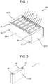
- FIG. 1 is a perspective view showing power supply device 100 of a first exemplary embodiment of the present invention.
- power supply device 100 includes a plurality of battery cells 1, a plurality of separators 2, and restraining member 3 that assembles the plurality of battery cells 1 and the plurality of separators 2.
- the plurality of battery cells 1 are disposed along one direction.
- Each of separators 2 is disposed between adjacent battery cells 1 among the plurality of battery cells 1.
- the plurality of separators 2 each have insulating properties and prevent a short circuit between adjacent battery cells 1. Further, separator 2 has heat insulating properties and suppresses heat transfer between the adjacent battery cells.
- the plurality of battery cells 1 are connected in series or in parallel via a bus bar (not shown).
- a voltage and a capacity of the power supply device are determined in accordance with a number of battery cells 1 connected in parallel and a number of battery cells 1 connected in series.
- battery cells 1 various secondary batteries such as a lithium ion secondary battery and a nickel hydrogen battery can be adopted.
- restraining member 3 includes a pair of end plates 32 disposed at both ends of the plurality of battery cells 1 stacked in a stacking direction, and a plurality of bind bars 34 fixed to the pair of end plates 32. End portions of bind bars 34 are connected to end plates 32. Each of bind bars 34 is fixed to each of end plates 32 via set screws 36.
- Bind bars 34 are each manufactured by processing a metal plate having a predetermined thickness to have a predetermined width. Bind bars 34 connect their end portions to end plates 32 to connect the pair of end plates 32, and hold battery cells 1 between end plates 32. Bind bars 34 fix the pair of end plates 32 with a predetermined size, thereby suppressing expansion of battery cells 1 stacked between end plates 32. When bind bars 34 are stretched, the expansion of battery cells 1 cannot be inhibited. Therefore, bind bars 34 are each manufactured by processing a metal plate to have a width and a thickness, the metal plate having enough strength to prevent the metal plate from stretching due to an expansion pressure of battery cell 1, for example, a stainless steel plate such as SUS304, or a metal plate such as a steel plate.
- bind bars 34 in FIG. 1 are fixed to end plates 32 with set screws 36, they do not necessarily have to be fixed with screw members. Specifically, bind bars 34 can be fixed by using welding, a locking structure, or the like. Further, while power supply device 100 of FIG. 1 has the configuration in which bind bars 34 are fixed to the side surfaces of end plates 32, a fixing structure of the end plates and the bind bars is not limited to the configuration shown in the drawing. A function required as bind bars 34 is to regulate a relative distance between the pair of end plates 32. End plates 32 and bind bars 34 may have any configuration as long as displacement of the pair of end plates can be regulated.
- battery cell 1 includes rectangular parallelepiped outer can 12 and sealing body 14 provided with positive and negative electrode terminals 16. Further, battery cell 1 has an electrode body housed in outer can 12, and outer can 12 is filled with an electrolytic solution, so that battery cell 1 has a characteristic of expanding or contracting due to charge and discharge, or deterioration.
- Outer can 12 is formed into a box shape having an opening.
- Sealing body 14 is welded to outer can 12 with the opening of outer can 12 closed.
- outer can 12 is manufactured by subjecting a metal plate of aluminum or an aluminum alloy to deep drawing. Similar to outer can 12, sealing body 14 is manufactured, using a metal plate of aluminum or an aluminum alloy.
- Positive and negative electrode terminals 16 are fixed to both end portions of sealing body 14.
- Sealing body 14 is welded in a state inserted into the opening portion of outer can 12.
- sealing body 14 is airtightly fixed to outer can 12 by irradiating a boundary between an outer circumference of sealing body 14 and an inner circumference of outer can 12 with a laser beam.
- a welded portion where the opening portion of the outer can and the sealing body are welded is formed along an upper end of the outer can.
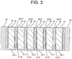
- each of separators 2 includes contact portion 21 that comes into contact with an adjacent battery cell, and thin portion 22 that is formed thinner than contact portion 21.
- Contact portion 21 is provided at a position corresponding to a central portion of outer can 12 of battery cell 1, and presses a wide surface of outer can 12 to suppress the expansion of battery cell 1.
- Thin portion 22 is provided adjacent to contact portion 21, and extends along the upper end of outer can 12 of adjacent battery cell 1.
- thin portion 22 is configured to be opposed to welded portion 18 where the opening portion of outer can 12 and sealing body 14 are welded, welded portion 18 being formed along the upper end of outer can 12. When welded portion 18 is pressed, a stress is concentrated on welded portion 18 and there is a risk that welded portion 18 is damaged.
- separator 2 has the configuration in which contact portion 21 protrudes from thin portion 22 toward battery cell 1, by which it is possible to prevent thin portion 22 from pressing welded portion 18.
- separator 2 shown in FIG. 3 has a step formed at a boundary between contact portion 21 and thin portion 22, a shape does not necessarily have to be such that a step is formed.
- Separator 2 shown in FIG. 3 is one example for clarifying the configuration, and for example, a shape in which a taper is provided at the boundary between the contact portion and the thin portion and the shape gradually changes can be adopted.
- battery cell 1 having the outer can and the sealing body made of a metal exposes the metal on a surface.
- a configuration is known in which in order to prevent a short circuit through condensed water or the like, the surface of outer can 12 is covered with a heat-shrinkable tube.
- the configuration in which the surface of outer can 12 is covered with a heat-shrinkable tube may also be adopted.
- contact portion 21 presses outer can 12 via the heat-shrinkable tube. Therefore, in the present invention, the contact between contact portion 21 and the outer can is not intended to be limited to direct contact, and a state is included where contact portion 21 indirectly presses outer can 12.
- separator 2 is configured to include a heat insulating member having heat insulating properties.
- the heat insulating member included in separator 2 is a sheet having a thickness of 0.1 mm to 1.5 mm, and includes a fiber sheet made of a woven fabric, a non-woven fabric, or the like, and a porous material supported between fibers of the fiber sheet.
- the heat insulating member preferable for the exemplary embodiment of the present invention has a thermal conductivity less than or equal to 0.02 W/(m ⁇ K).
- the porous material preferably has a void structure such as xerogel or aerogel.
- silica aerogel and silica xerogel each have a nano-sized void structure that regulates movement of air molecules, and have excellent heat insulating performance.
- silica xerogel can stably maintain its structure against external pressure. Since silica particles have a high melting point, silica xerogel also has high heat resistance.
- Various fibers can be used as the fiber making up the fiber sheet, and may include flame-retardant fiber having heat resistance. As the flame-retardant fiber, acrylic oxide fiber, flame-retardant vinylon fiber, polyetherimide fiber, aramid fiber, glass fiber, and the like are known. In particular, since the fiber sheet contains glass fiber, it can be expected to improve rigidity and suppress creep deformation in addition to improvement of heat resistance.
- the heat insulating member using the fiber sheet containing the flame-retardant fiber is not damaged even if battery cell 1 is heated to a high temperature due to thermal runaway, and can stably cut off conduction of thermal energy to effectively inhibit induction of the thermal runaway.
- the fiber contained in the heat insulating member is preferably synthetic fiber having a small fiber diameter.
- the heat insulating properties of the heat insulating member arise from characteristics of powder described later, and by using the synthetic fiber having a small fiber diameter as a base material, a large amount of powder can be contained in the heat insulating material.
- the fiber sheet used in the present exemplary embodiment is preferably 1 ⁇ m to 30 ⁇ m from the viewpoint of achieving both thermal conductivity and productivity.
- the heat insulating member may be molded by adding a thermoplastic resin.
- a thermoplastic resin By adjusting an additive when the heat insulating member is formed in this way, it is possible to appropriately design physical properties such as elasticity while maintaining heat insulating properties, heat resistance, and the like in accordance with required performance.
- various characteristics can be imparted by coating a surface of the heat insulating member. For example, by covering with a coating layer made of alumina having a low emissivity, influence by radiant heat transfer of the heat insulating member can be suppressed.
- FIG. 4 is a perspective view for describing one example of separator 2 of FIG. 1 .
- Separator 2A shown in FIG. 4 includes sandwiched and fixed plate portion 23A molded of a highly moldable resin, and heat insulating member 24A disposed on a surface of sandwiched and fixed plate portion 23A.
- heat insulating member 24A the above-described heat insulating member is preferably used.
- Sandwiched and fixed plate portion 23A has contact portion 21 and thin portion 22. Separator 2A can prevent welded portion 18 from being pressed by thin portion 22 by molding sandwiched and fixed plate portion 23A of a highly moldable resin. Further, as shown in FIG.
- peripheral wall 27 may be provided that protrudes from a peripheral edge of sandwiched and fixed plate portion 23A toward adjacent battery cells 1. Peripheral wall 27 extends along a side surface of battery cell 1, so that the displacement of battery cell 1 can be suppressed, and battery cell 1 can be held. By adopting separator 2 having peripheral wall 27, it is possible to improve a function such as assemblability of the power supply device.
- a shape of heat insulating member 24A of separator 2A having the above-described configuration is not particularly limited, and a thickness, the shape, a disposition position, and the like can be freely selected in accordance with required heat insulating performance. That is, by dividing separator 2A into a portion formed of a resin having high moldability and a portion for ensuring the heat insulating performance, even a heat insulating member having low moldability can be adopted as the heat insulating member. While the above-described heat insulating member has low moldability and is difficult to be molded into a shape other than a sheet shape, such a heat insulating member can be used as long as the configuration of separator 2A is adopted.
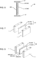
- FIGS. 5 and 6 are perspective views for describing one example of separator 2 of FIG. 1 .
- Separator 2B shown in FIGS. 5 and 6 includes sandwiched and fixed plate portion 23B molded of a highly moldable resin and heat insulating member 24B disposed inside sandwiched and fixed plate portion 23B.
- heat insulating member 24B the above-described heat insulating member is preferably used.
- Sandwiched and fixed plate portion 23B has contact portion 21 and thin portion 22.
- Separator 2B can prevent welded portion 18 from being pressed by thin portion 22 by molding sandwiched and fixed plate portion 23B of a highly moldable resin.
- peripheral wall 27 may be provided that protrudes from a peripheral edge of sandwiched and fixed plate portion 23B toward adjacent battery cells 1.
- heat insulating member 24B is insert-molded of the highly moldable resin such that heat insulating member 24B is located inside sandwiched and fixed plate portion 23B. Note that while it depends on the characteristics of the used heat insulating member, it is preferable that a surface of heat insulating member 24B is covered with a film for preventing penetration of the resin. Some heat insulating members having a plurality of pores achieve heat insulation by an air layer in the pores. In the case of such a heat insulating member, if the pores are filled with the resin, there is a risk that the heat insulating performance is significantly deteriorated.
- the film can suppress the penetration of the resin and suppress the deterioration of the heat insulating performance. Note that in the case of a heat insulating member that does not have a risk that the pores are filled with the resin, the heat insulating member does not necessarily have to be covered with a film.
- heat insulating member 24B is configured to be covered with a highly moldable resin in separator 2B having the above configuration, a shape of heat insulating member 24B is not particularly limited, and a thickness and the shape are adjusted in accordance with required heat insulating performance.
- FIG. 7 is a perspective view for describing one example of separator 2 of FIG. 1 .
- Separator 2C shown in FIG. 7 includes heat insulating member 24C molded by adding a thermoplastic resin.
- heat insulating member 24C the above-described heat insulating member is preferably used.
- Heat insulating member 24C containing the thermoplastic resin can be molded into a plate shape having contact portion 21 and thin portion 22 by press-molding heat insulating member 24C in a heated state. Specifically, by partially press-molding sheet-shaped heat insulating member 24C, separator 2C having thin portion 22 and contact portion 21 can be molded. In separator 2C molded in this way, the press-molded portion corresponds to thin portion 22. With the above configuration, separator 2C can prevent welded portion 18 from being pressed by thin portion 22.
- separator 2C can also be molded by pressing the sheet-shaped heat insulating member 24C so as to have a partially different thickness. In the case of this configuration, a compressibility of contact portion 21 and thin portion 22 are different. Heat insulating member 24C containing a thermoplastic resin is heated and compressed to improve its rigidity.
- separator 2C having the above configuration, a separator having contact portion 21 and thin portion 22 can be molded by using a sheet-shaped heat insulating member.
- the separator having this configuration is preferable for a separator having a relatively simple shape.
- FIG. 8 is a perspective view for showing one example of separator 2 of FIG. 1 .
- Separator 2D shown in FIG. 8 is made up of a plurality of sheet-shaped heat insulating members 24D. Specifically, separator 2D is formed by laminating the plurality of heat insulating members 24D having different dimensions.
- the plurality of heat insulating members 24D configuring separator 2D include first sheet 25D having an area smaller than a wide surface of an outer can of the adjacent battery cell, and second sheet 26D having an area larger than first sheet 25D.
- An adhesive layer is interposed between first sheet 25D and second sheet 26D, and first sheet 25D and second sheet 26D are joined to each other.
- a configuration of the adhesive layer may be any configuration, and various materials such as an adhesive and a double-sided tape can be used.
- First sheet 25D is located in a center of the second sheet.
- separator 2D having the above configuration is preferable for molding the separator using a heat insulating member that is difficult to mold thickly.
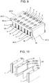
- FIG. 9 is a perspective view showing power supply device 200 according to a second exemplary embodiment of the present invention.
- power supply device 200 of the second exemplary embodiment has a configuration in which cooling gap 4 is formed between separator 2 and battery cell 1. Since high temperature promotes deterioration of battery cell 1, battery cell 1 has a configuration in which the deterioration of the battery can be suppressed by cooling battery cell 1.
- bind bars 34 are preferably shaped such that cooling air can be introduced into cooling gap 4 between separator 2 and battery cell 1.
- power supply device 200 illustrated in FIG. 9 has a configuration in which a pair of bind bars 34 are provided on one side surface, and an inlet of each of cooling gaps 4 faces between the pair of bind bars 34.
- FIGS. 10 and 11 are perspective views for showing one example of separator 2 of FIG. 9 .
- Separator 2E shown in FIGS. 10 and 11 includes sandwiched and fixed plate portion 23E molded of a highly moldable resin, and heat insulating member 24E disposed on a surface of sandwiched and fixed plate portion 23E.
- heat insulating member 24E the above-described heat insulating member is preferably used.
- Sandwiched and fixed plate portion 23E includes contact portion 21, thin portion 22, and a plurality of ribs 28, and contact portion 21 is formed on one surface of sandwiched and fixed plate portion 23E, and the plurality of ribs 28 are formed on another surface of sandwiched and fixed plate portion 23E.
- the plurality of ribs 28 comes into contact with the outer can of the adjacent battery cell to form cooling gap 4 between adjacent ribs 28.
- Battery cell 1 can be cooled by cooling gas such as air forcibly blown into cooling gap 4 flowing through cooling gap 4 of separator 2E.
- heat insulating member 24E is disposed on the surface where contact portion 21 of sandwiched and fixed plate portion 23E is formed.
- Heat insulating member 24E is preferably a highly flexible heat insulating member.
- the highly flexible heat insulating member is pressed by contact portion 21 of sandwiched and fixed plate portion 23E, and indirectly presses the wide surface of outer can 12 of battery cell 1. According to this configuration, even when heat insulating member 24E is larger than contact portion 21 of sandwiched and fixed plate portion 23E, deformation of heat insulating member 24E can suppress a load on welded portion 18.
- FIGS. 12 and 13 are perspective views for showing one example of separator 2 of FIG. 9 .
- Separator 2F shown in FIGS. 12 and 13 includes sandwiched and fixed plate portion 23F molded of a highly moldable resin, and heat insulating member 24F disposed on a surface of sandwiched and fixed plate portion 23F.
- heat insulating member 24F the above-described heat insulating member is preferably used.
- Sandwiched and fixed plate portion 23F includes contact portion 21, thin portion 22, and a plurality of ribs 28, and contact portion 21 is formed on one surface of sandwiched and fixed plate portion 23F, and the plurality of ribs 28 are formed on another surface of sandwiched and fixed plate portion 23F.
- heat insulating member 24F is disposed on the surface where the plurality of ribs 28 of sandwiched and fixed plate portion 23F are formed.
- a power supply device using the separator having this configuration can be expected to have an effect of suppressing local deformation of the outer can due to the ribs 28.
- ribs for partitioning the cooling gap are required. Therefore, a contact area between the surface of sandwiched and fixed plate portion 23F on which the ribs 28 are formed, and the outer can is smaller than a contact area between contact portion 21 of sandwiched and fixed plate portion 23F and the outer can.
- ribs 28 come into indirect contact with outer can 12, so that the stress can be dispersed.
- the pair of end plates 32 are fixed to a predetermined size via the restraining member, and battery cells 1 stacked between them are fixed in a compressed state, and the expansion of the battery cells can be suppressed. Therefore, the stress is concentrated on the contact parts between the respective members disposed between the pair of end plates 32.
- separator 2 disposed between adjacent battery cells 1 since in separator 2 disposed between adjacent battery cells 1, thin portion 22 is provided at the position opposed to welded portion 18 where the opening portion of the outer can and the sealing body of the adjacent battery cell are welded, it is possible to suppress the load on welded portion 18. That is, each of the power supply devices according to the exemplary embodiments of the present invention can suppress the heat transfer between the adjacent battery cells, and can prevent the stress from being concentrated on the welded portions of the battery cells.
Landscapes
- Chemical & Material Sciences (AREA)
- Chemical Kinetics & Catalysis (AREA)
- Electrochemistry (AREA)
- General Chemical & Material Sciences (AREA)
- Engineering & Computer Science (AREA)
- Manufacturing & Machinery (AREA)
- Secondary Cells (AREA)
- Battery Mounting, Suspending (AREA)
- Sealing Battery Cases Or Jackets (AREA)
Abstract
Description
- The present invention relates to a power supply device including a plurality of battery cells.
- In recent years, electric vehicles that each use a power supply device for propulsion have become widespread. Various configurations of electric vehicles are known. For example, an electric vehicle (BEV: Battery Electric Vehicle) equipped with a driving motor, a hybrid car (HEV: Hybrid Electric Vehicle) equipped with an engine in addition to a motor and so on can be cited. In the power supply device mounted on each of these electric vehicles, a plurality of battery cells are used. Each of the battery cells is a rechargeable secondary battery such as a lithium ion battery or a nickel hydrogen battery. In this type of power supply device, it is desirable that a space occupied by the power supply device is small, and it is required to improve space efficiency. As a power supply device having excellent space efficiency, a power supply device including a plurality of square batteries stacked in one direction and a restraining member for assembling the plurality of square batteries is known (PTL 1). The power supply device of
PTL 1 includes a plurality of battery cells and insulating separators disposed between adjacent battery cells among the plurality of battery cells. - PTL 1: Unexamined
Japanese Patent Publication No. 2011-034775 - It is known that a secondary battery causes various problems when temperature becomes high. In particular, if a chemical reaction of an internal power generation element is promoted by heat, there is a risk that the heat generated by the chemical reaction further causes self-heating. On the other hand, the power supply device of
PTL 1 has a configuration in which the battery cells are disposed close to each other, and thus, when one of the battery cells enters a self-heated state due to some abnormality, the heat is transferred to the battery cell adjacent to the one battery cell. When an amount of the heat transferred from the battery cell in the abnormal state to the adjacent battery cell is large, there is a risk that the transferred heat promotes a chemical reaction of the power generation element inside the adjacent battery cell. In order to suppress such heat propagation, it is necessary to thicken the separator provided for insulation, but such a configuration causes an increase in the size of the power supply device and causes a problem that space efficiency is lowered. - The present invention has been made to solve such a problem, and a main object of the present invention is to provide a power supply device including a configuration for suppressing heat transfer between adjacent battery cells while suppressing an increase in size of the power supply device.
- A power supply device according to an aspect of the present invention includes a plurality of battery cells each having a square outer shape, a plurality of separators for insulating adjacent battery cells among the plurality of battery cells, and a restraining member that assembles the plurality of battery cells and the plurality of separators. Each of the separators has heat insulating properties. Further, each of the separators is disposed between the adjacent battery cells. Further, each of the separators includes a contact portion that comes into contact with the adjacent battery cell, and a thin portion formed thinner than the contact portion and separated from a surface of the adjacent battery cell.
- According to the power supply device according to the present invention, heat can be insulated by the separator interposed between the adjacent battery cells, so that an effect that heat transfer between the adjacent battery cells can be suppressed while suppressing an increase in size of the power supply device is exerted.
-
-
FIG. 1 is a perspective view of a power supply device according to a first exemplary embodiment of the present invention. -
FIG. 2 is a perspective view of a battery cell ofFIG. 1 . -
FIG. 3 is a cross-sectional view of the power supply device ofFIG. 1 . -
FIG. 4 is a perspective view showing one example of a separator ofFIG. 1 . -
FIG. 5 is a perspective view showing one example of the separator ofFIG. 1 . -
FIG. 6 is a cross-sectional view of a separator ofFIG. 5 . -
FIG. 7 is a perspective view showing one example of the separator ofFIG. 1 . -
FIG. 8 is a perspective view showing one example of the separator ofFIG. 1 . -
FIG. 9 is a perspective view of a power supply device according to a second exemplary embodiment of the present invention. -
FIG. 10 is a perspective view showing one example of a separator ofFIG. 9 . -
FIG. 11 is a perspective view when a viewpoint ofFIG. 10 is changed. -
FIG. 12 is a perspective view showing one example of the separator ofFIG. 9 . -
FIG. 13 is a perspective view when a viewpoint ofFIG. 12 is changed. - First, a background to an idea of a configuration of a heat insulating member of a certain aspect of the present invention will be described. As shown in
PTL 1, in a typical power supply device, a plurality of battery cells are disposed in the same orientation. Insulating separators are each disposed between adjacent battery cells in order to prevent a short circuit between the adjacent battery cells. On the other hand, in recent years, as a capacity of a battery cell has increased, an amount of energy possessed by each battery cell has tended to increase. - As described above, since the power supply device of
PTL 1 has a configuration in which the battery cells are disposed close to one another, when one of the battery cells enters in a self-heated state due to some abnormality, the heat is transferred to the battery cell adjacent to the one battery cell. When the amount of heat transferred from the battery cell in the abnormal state to the adjacent battery cell is large, there is a risk that the transferred heat promotes a chemical reaction of a power generation element inside the adjacent battery cell. When the capacity of the battery cell is increased, the amount of heat transferred from the battery cell in an abnormal state to the adjacent battery cell becomes relatively larger, so that there is a possibility that this phenomenon becomes a problem. - In response to this problem, the inventors of the present invention have studied a configuration that employs a separator having heat insulating properties. In the conventional power supply device, a resin having high moldability is used for the separator. Therefore, in order to improve the heat insulating properties, it is necessary to increase a material thickness of the separator. However, if a thickness of the separator is increased, a size of the power supply device is increased, and there is a problem that a capacity per volume of the power supply device is reduced. In view of the above-described actual situation, the present inventors have studied a configuration for reducing an increase in the thickness of the separator while maintaining moldability.
-
FIG. 1 is a perspective view showingpower supply device 100 of a first exemplary embodiment of the present invention. As shown inFIG. 1 ,power supply device 100 includes a plurality ofbattery cells 1, a plurality ofseparators 2, and restrainingmember 3 that assembles the plurality ofbattery cells 1 and the plurality ofseparators 2. The plurality ofbattery cells 1 are disposed along one direction. Each ofseparators 2 is disposed betweenadjacent battery cells 1 among the plurality ofbattery cells 1. The plurality ofseparators 2 each have insulating properties and prevent a short circuit betweenadjacent battery cells 1. Further,separator 2 has heat insulating properties and suppresses heat transfer between the adjacent battery cells. The plurality ofbattery cells 1 are connected in series or in parallel via a bus bar (not shown). Inpower supply device 100, a voltage and a capacity of the power supply device are determined in accordance with a number ofbattery cells 1 connected in parallel and a number ofbattery cells 1 connected in series. As each ofbattery cells 1, various secondary batteries such as a lithium ion secondary battery and a nickel hydrogen battery can be adopted. - As shown in
FIG. 1 , restrainingmember 3 includes a pair ofend plates 32 disposed at both ends of the plurality ofbattery cells 1 stacked in a stacking direction, and a plurality ofbind bars 34 fixed to the pair ofend plates 32. End portions of bind bars 34 are connected to endplates 32. Each of bind bars 34 is fixed to each ofend plates 32 via set screws 36. - Bind bars 34 are each manufactured by processing a metal plate having a predetermined thickness to have a predetermined width. Bind bars 34 connect their end portions to end
plates 32 to connect the pair ofend plates 32, and holdbattery cells 1 betweenend plates 32. Bind bars 34 fix the pair ofend plates 32 with a predetermined size, thereby suppressing expansion ofbattery cells 1 stacked betweenend plates 32. When bind bars 34 are stretched, the expansion ofbattery cells 1 cannot be inhibited. Therefore, bind bars 34 are each manufactured by processing a metal plate to have a width and a thickness, the metal plate having enough strength to prevent the metal plate from stretching due to an expansion pressure ofbattery cell 1, for example, a stainless steel plate such as SUS304, or a metal plate such as a steel plate. - Note that while bind bars 34 in
FIG. 1 are fixed toend plates 32 withset screws 36, they do not necessarily have to be fixed with screw members. Specifically, bind bars 34 can be fixed by using welding, a locking structure, or the like. Further, whilepower supply device 100 ofFIG. 1 has the configuration in which bind bars 34 are fixed to the side surfaces ofend plates 32, a fixing structure of the end plates and the bind bars is not limited to the configuration shown in the drawing. A function required as bind bars 34 is to regulate a relative distance between the pair ofend plates 32.End plates 32 and bind bars 34 may have any configuration as long as displacement of the pair of end plates can be regulated. - As shown in
FIG. 2 ,battery cell 1 includes rectangular parallelepiped outer can 12 and sealingbody 14 provided with positive andnegative electrode terminals 16. Further,battery cell 1 has an electrode body housed inouter can 12, andouter can 12 is filled with an electrolytic solution, so thatbattery cell 1 has a characteristic of expanding or contracting due to charge and discharge, or deterioration. - Outer can 12 is formed into a box shape having an opening. Sealing
body 14 is welded toouter can 12 with the opening ofouter can 12 closed. Specifically,outer can 12 is manufactured by subjecting a metal plate of aluminum or an aluminum alloy to deep drawing. Similar toouter can 12, sealingbody 14 is manufactured, using a metal plate of aluminum or an aluminum alloy. Positive andnegative electrode terminals 16 are fixed to both end portions of sealingbody 14. Sealingbody 14 is welded in a state inserted into the opening portion ofouter can 12. Typically, sealingbody 14 is airtightly fixed toouter can 12 by irradiating a boundary between an outer circumference of sealingbody 14 and an inner circumference ofouter can 12 with a laser beam. - In
battery cell 1 having the above configuration, a welded portion where the opening portion of the outer can and the sealing body are welded is formed along an upper end of the outer can. Whenbattery cell 1 expands, there is a risk that the welded portion is damaged, and thus, it is important to suppress deformation of an upper end portion of the outer can. - As shown in
FIG. 3 , each ofseparators 2 includescontact portion 21 that comes into contact with an adjacent battery cell, andthin portion 22 that is formed thinner thancontact portion 21.Contact portion 21 is provided at a position corresponding to a central portion ofouter can 12 ofbattery cell 1, and presses a wide surface ofouter can 12 to suppress the expansion ofbattery cell 1.Thin portion 22 is provided adjacent to contactportion 21, and extends along the upper end ofouter can 12 ofadjacent battery cell 1. In particular,thin portion 22 is configured to be opposed to weldedportion 18 where the opening portion ofouter can 12 and sealingbody 14 are welded, weldedportion 18 being formed along the upper end ofouter can 12. When weldedportion 18 is pressed, a stress is concentrated on weldedportion 18 and there is a risk that weldedportion 18 is damaged. However,separator 2 has the configuration in whichcontact portion 21 protrudes fromthin portion 22 towardbattery cell 1, by which it is possible to preventthin portion 22 from pressing weldedportion 18. - Note that while
separator 2 shown inFIG. 3 has a step formed at a boundary betweencontact portion 21 andthin portion 22, a shape does not necessarily have to be such that a step is formed.Separator 2 shown inFIG. 3 is one example for clarifying the configuration, and for example, a shape in which a taper is provided at the boundary between the contact portion and the thin portion and the shape gradually changes can be adopted. - Note that
battery cell 1 having the outer can and the sealing body made of a metal exposes the metal on a surface. Typically, a configuration is known in which in order to prevent a short circuit through condensed water or the like, the surface ofouter can 12 is covered with a heat-shrinkable tube. In the present exemplary embodiment, if necessary, the configuration in which the surface ofouter can 12 is covered with a heat-shrinkable tube may also be adopted. Whenbattery cell 1 having the configuration in which the surface ofouter can 12 is covered with the heat-shrinkable tube is used,contact portion 21 pressesouter can 12 via the heat-shrinkable tube. Therefore, in the present invention, the contact betweencontact portion 21 and the outer can is not intended to be limited to direct contact, and a state is included wherecontact portion 21 indirectly pressesouter can 12. - On the other hand, as described above, when the amount of heat transferred from the battery cell in an abnormal state to the adjacent battery cell is large, there is a risk that the transferred heat promotes a chemical reaction of the power generation element inside the adjacent battery cell, and thus,
separator 2 is configured to include a heat insulating member having heat insulating properties. - The heat insulating member included in
separator 2 is a sheet having a thickness of 0.1 mm to 1.5 mm, and includes a fiber sheet made of a woven fabric, a non-woven fabric, or the like, and a porous material supported between fibers of the fiber sheet. The heat insulating member preferable for the exemplary embodiment of the present invention has a thermal conductivity less than or equal to 0.02 W/(m·K). The porous material preferably has a void structure such as xerogel or aerogel. In particular, silica aerogel and silica xerogel each have a nano-sized void structure that regulates movement of air molecules, and have excellent heat insulating performance. In addition, silica xerogel can stably maintain its structure against external pressure. Since silica particles have a high melting point, silica xerogel also has high heat resistance. Various fibers can be used as the fiber making up the fiber sheet, and may include flame-retardant fiber having heat resistance. As the flame-retardant fiber, acrylic oxide fiber, flame-retardant vinylon fiber, polyetherimide fiber, aramid fiber, glass fiber, and the like are known. In particular, since the fiber sheet contains glass fiber, it can be expected to improve rigidity and suppress creep deformation in addition to improvement of heat resistance. The heat insulating member using the fiber sheet containing the flame-retardant fiber is not damaged even ifbattery cell 1 is heated to a high temperature due to thermal runaway, and can stably cut off conduction of thermal energy to effectively inhibit induction of the thermal runaway. - Note that the fiber contained in the heat insulating member is preferably synthetic fiber having a small fiber diameter. The heat insulating properties of the heat insulating member arise from characteristics of powder described later, and by using the synthetic fiber having a small fiber diameter as a base material, a large amount of powder can be contained in the heat insulating material. The fiber sheet used in the present exemplary embodiment is preferably 1 µm to 30 µm from the viewpoint of achieving both thermal conductivity and productivity.
- Further, the heat insulating member may be molded by adding a thermoplastic resin. By adjusting an additive when the heat insulating member is formed in this way, it is possible to appropriately design physical properties such as elasticity while maintaining heat insulating properties, heat resistance, and the like in accordance with required performance. Note that various characteristics can be imparted by coating a surface of the heat insulating member. For example, by covering with a coating layer made of alumina having a low emissivity, influence by radiant heat transfer of the heat insulating member can be suppressed.
-
FIG. 4 is a perspective view for describing one example ofseparator 2 ofFIG. 1 .Separator 2A shown inFIG. 4 includes sandwiched and fixedplate portion 23A molded of a highly moldable resin, and heat insulatingmember 24A disposed on a surface of sandwiched and fixedplate portion 23A. Asheat insulating member 24A, the above-described heat insulating member is preferably used. Sandwiched and fixedplate portion 23A hascontact portion 21 andthin portion 22.Separator 2A can prevent weldedportion 18 from being pressed bythin portion 22 by molding sandwiched and fixedplate portion 23A of a highly moldable resin. Further, as shown inFIG. 4 , if necessary,peripheral wall 27 may be provided that protrudes from a peripheral edge of sandwiched and fixedplate portion 23A towardadjacent battery cells 1.Peripheral wall 27 extends along a side surface ofbattery cell 1, so that the displacement ofbattery cell 1 can be suppressed, andbattery cell 1 can be held. By adoptingseparator 2 havingperipheral wall 27, it is possible to improve a function such as assemblability of the power supply device. - A shape of
heat insulating member 24A ofseparator 2A having the above-described configuration is not particularly limited, and a thickness, the shape, a disposition position, and the like can be freely selected in accordance with required heat insulating performance. That is, by dividingseparator 2A into a portion formed of a resin having high moldability and a portion for ensuring the heat insulating performance, even a heat insulating member having low moldability can be adopted as the heat insulating member. While the above-described heat insulating member has low moldability and is difficult to be molded into a shape other than a sheet shape, such a heat insulating member can be used as long as the configuration ofseparator 2A is adopted. -
FIGS. 5 and6 are perspective views for describing one example ofseparator 2 ofFIG. 1 .Separator 2B shown inFIGS. 5 and6 includes sandwiched and fixedplate portion 23B molded of a highly moldable resin and heat insulatingmember 24B disposed inside sandwiched and fixedplate portion 23B. Asheat insulating member 24B, the above-described heat insulating member is preferably used. Sandwiched and fixedplate portion 23B hascontact portion 21 andthin portion 22.Separator 2B can prevent weldedportion 18 from being pressed bythin portion 22 by molding sandwiched and fixedplate portion 23B of a highly moldable resin. Further, as shown inFIGS. 5 and6 , if necessary,peripheral wall 27 may be provided that protrudes from a peripheral edge of sandwiched and fixedplate portion 23B towardadjacent battery cells 1. - Specifically, in
separator 2B,heat insulating member 24B is insert-molded of the highly moldable resin such that heat insulatingmember 24B is located inside sandwiched and fixedplate portion 23B. Note that while it depends on the characteristics of the used heat insulating member, it is preferable that a surface ofheat insulating member 24B is covered with a film for preventing penetration of the resin. Some heat insulating members having a plurality of pores achieve heat insulation by an air layer in the pores. In the case of such a heat insulating member, if the pores are filled with the resin, there is a risk that the heat insulating performance is significantly deteriorated. By insert-moldingheat insulating member 24B covered with the film, the film can suppress the penetration of the resin and suppress the deterioration of the heat insulating performance. Note that in the case of a heat insulating member that does not have a risk that the pores are filled with the resin, the heat insulating member does not necessarily have to be covered with a film. - Since
heat insulating member 24B is configured to be covered with a highly moldable resin inseparator 2B having the above configuration, a shape ofheat insulating member 24B is not particularly limited, and a thickness and the shape are adjusted in accordance with required heat insulating performance. -
FIG. 7 is a perspective view for describing one example ofseparator 2 ofFIG. 1 . Separator 2C shown inFIG. 7 includesheat insulating member 24C molded by adding a thermoplastic resin. Asheat insulating member 24C, the above-described heat insulating member is preferably used. Heat insulatingmember 24C containing the thermoplastic resin can be molded into a plate shape havingcontact portion 21 andthin portion 22 by press-moldingheat insulating member 24C in a heated state. Specifically, by partially press-molding sheet-shapedheat insulating member 24C, separator 2C havingthin portion 22 andcontact portion 21 can be molded. In separator 2C molded in this way, the press-molded portion corresponds tothin portion 22. With the above configuration, separator 2C can prevent weldedportion 18 from being pressed bythin portion 22. - Note that separator 2C can also be molded by pressing the sheet-shaped
heat insulating member 24C so as to have a partially different thickness. In the case of this configuration, a compressibility ofcontact portion 21 andthin portion 22 are different. Heat insulatingmember 24C containing a thermoplastic resin is heated and compressed to improve its rigidity. - In separator 2C having the above configuration, a separator having
contact portion 21 andthin portion 22 can be molded by using a sheet-shaped heat insulating member. The separator having this configuration is preferable for a separator having a relatively simple shape. -
FIG. 8 is a perspective view for showing one example ofseparator 2 ofFIG. 1 .Separator 2D shown inFIG. 8 is made up of a plurality of sheet-shapedheat insulating members 24D. Specifically,separator 2D is formed by laminating the plurality ofheat insulating members 24D having different dimensions. The plurality ofheat insulating members 24D configuring separator 2D includefirst sheet 25D having an area smaller than a wide surface of an outer can of the adjacent battery cell, andsecond sheet 26D having an area larger thanfirst sheet 25D. An adhesive layer is interposed betweenfirst sheet 25D andsecond sheet 26D, andfirst sheet 25D andsecond sheet 26D are joined to each other. A configuration of the adhesive layer may be any configuration, and various materials such as an adhesive and a double-sided tape can be used.First sheet 25D is located in a center of the second sheet. With the above configuration,separator 2D havingthin portion 22 andcontact portion 21 can be molded, and the pressure of weldedportion 18 bythin portion 22 can be prevented. - Note that by laminating a plurality of
first sheets 25D, a size of a gap betweenthin portion 22 andbattery cell 1 can be adjusted. Therefore,separator 2D having the above configuration is preferable for molding the separator using a heat insulating member that is difficult to mold thickly. -
FIG. 9 is a perspective view showing power supply device 200 according to a second exemplary embodiment of the present invention. Note that in the following description, components similar to those in the first exemplary embodiment are denoted by the same reference marks, and description thereof will be omitted. As shown inFIG. 9 , power supply device 200 of the second exemplary embodiment has a configuration in whichcooling gap 4 is formed betweenseparator 2 andbattery cell 1. Since high temperature promotes deterioration ofbattery cell 1,battery cell 1 has a configuration in which the deterioration of the battery can be suppressed by coolingbattery cell 1. Note that as illustrated inFIG. 9 , bind bars 34 are preferably shaped such that cooling air can be introduced intocooling gap 4 betweenseparator 2 andbattery cell 1. Specifically, power supply device 200 illustrated inFIG. 9 has a configuration in which a pair of bind bars 34 are provided on one side surface, and an inlet of each ofcooling gaps 4 faces between the pair of bind bars 34. -
FIGS. 10 and11 are perspective views for showing one example ofseparator 2 ofFIG. 9 .Separator 2E shown inFIGS. 10 and11 includes sandwiched and fixedplate portion 23E molded of a highly moldable resin, and heat insulatingmember 24E disposed on a surface of sandwiched and fixedplate portion 23E. Asheat insulating member 24E, the above-described heat insulating member is preferably used. Sandwiched and fixedplate portion 23E includescontact portion 21,thin portion 22, and a plurality ofribs 28, andcontact portion 21 is formed on one surface of sandwiched and fixedplate portion 23E, and the plurality ofribs 28 are formed on another surface of sandwiched and fixedplate portion 23E. The plurality ofribs 28 comes into contact with the outer can of the adjacent battery cell to formcooling gap 4 betweenadjacent ribs 28.Battery cell 1 can be cooled by cooling gas such as air forcibly blown intocooling gap 4 flowing throughcooling gap 4 ofseparator 2E. - In
separator 2E,heat insulating member 24E is disposed on the surface wherecontact portion 21 of sandwiched and fixedplate portion 23E is formed. Heat insulatingmember 24E is preferably a highly flexible heat insulating member. The highly flexible heat insulating member is pressed bycontact portion 21 of sandwiched and fixedplate portion 23E, and indirectly presses the wide surface ofouter can 12 ofbattery cell 1. According to this configuration, even whenheat insulating member 24E is larger thancontact portion 21 of sandwiched and fixedplate portion 23E, deformation ofheat insulating member 24E can suppress a load on weldedportion 18. Note that whenheat insulating member 24E having relatively high rigidity is adopted, it is preferable that an area ofheat insulating member 24E is smaller than that ofcontact portion 21, or thatcontact portion 21 is formed ofheat insulating member 24E. -
FIGS. 12 and 13 are perspective views for showing one example ofseparator 2 ofFIG. 9 .Separator 2F shown inFIGS. 12 and 13 includes sandwiched and fixedplate portion 23F molded of a highly moldable resin, and heat insulatingmember 24F disposed on a surface of sandwiched and fixedplate portion 23F. Asheat insulating member 24F, the above-described heat insulating member is preferably used. Sandwiched and fixedplate portion 23F includescontact portion 21,thin portion 22, and a plurality ofribs 28, andcontact portion 21 is formed on one surface of sandwiched and fixedplate portion 23F, and the plurality ofribs 28 are formed on another surface of sandwiched and fixedplate portion 23F. - In
separator 2F, heat insulatingmember 24F is disposed on the surface where the plurality ofribs 28 of sandwiched and fixedplate portion 23F are formed. A power supply device using the separator having this configuration can be expected to have an effect of suppressing local deformation of the outer can due to theribs 28. In the case of the separator having the cooling gap, ribs for partitioning the cooling gap are required. Therefore, a contact area between the surface of sandwiched and fixedplate portion 23F on which theribs 28 are formed, and the outer can is smaller than a contact area betweencontact portion 21 of sandwiched and fixedplate portion 23F and the outer can. Therefore, there is a risk that a stress is concentrated on the outer can with whichribs 28 are in contact as compared with the outer can with which the contact portion is in contact. In the exemplary embodiment including the separators shown inFIGS. 11 and 12 ,ribs 28 come into indirect contact withouter can 12, so that the stress can be dispersed. - According to the above configuration, the pair of
end plates 32 are fixed to a predetermined size via the restraining member, andbattery cells 1 stacked between them are fixed in a compressed state, and the expansion of the battery cells can be suppressed. Therefore, the stress is concentrated on the contact parts between the respective members disposed between the pair ofend plates 32. In the configurations of the above-described exemplary embodiments, since inseparator 2 disposed betweenadjacent battery cells 1,thin portion 22 is provided at the position opposed to weldedportion 18 where the opening portion of the outer can and the sealing body of the adjacent battery cell are welded, it is possible to suppress the load on weldedportion 18. That is, each of the power supply devices according to the exemplary embodiments of the present invention can suppress the heat transfer between the adjacent battery cells, and can prevent the stress from being concentrated on the welded portions of the battery cells. - The present invention has been described above on the basis of the exemplary embodiments. It will be appreciated by those skilled in the art that these exemplary embodiments are exemplary and that various modifications can be made for each of their components and combinations of processing processes, and that such modifications are also within the scope of the present invention.
-
- 100,200
- power supply device
- 1
- battery cell
- 12
- outer can
- 14
- sealing body
- 16
- electrode terminal
- 18
- welded portion
- 2, 2A, 2B, 2C, 2D, 2E, 2F
- separator
- 21
- contact portion
- 22
- thin portion
- 23A, 23B, 23E, 23F
- sandwiched and fixed plate portion
- 24A, 24B, 24C, 24D, 24E, 24F
- heat insulating member
- 25D
- first sheet
- 26D
- second sheet
- 27
- peripheral wall
- 28
- rib
- 3
- restraining member
- 32
- end plate
- 34
- bind bar
- 36
- set screw
- 4
- cooling gap
Claims (9)
- A power supply device comprising:a plurality of battery cells each having a square outer shape;a plurality of separators each insulating adjacent battery cells among the plurality of battery cells,each of the plurality of separators having heat insulating properties, being disposed between battery cells adjacent to the each of the plurality of separators, and including a contact portion and a thin portion,the contact portion coming into contact with a battery cell adjacent to the each of the plurality of separators among the plurality of battery cells, and the thin portion being formed thinner than the contact portion; anda restraining member that assembles the plurality of battery cells and the plurality of separators.
- The power supply device according to claim 1, wherein
each of the plurality of battery cells includes:an outer can having a flat rectangular parallelepiped shape and having an opening; anda sealing body welded to an opening portion of the outer can, andthe thin portion extends along a welded portion between a sealing body and an opening portion of an outer can of a battery cell adjacent to the thin portion. - The power supply device according to claim 1 or claim 2, wherein each of the plurality of separators includes a sandwiched and fixed plate portion provided with the contact portion and the thin portion, and a heat insulating member disposed between the sandwiched and fixed plate portion and a battery cell adjacent to the sandwiched and fixed plate portion.
- The power supply device according to claim 1 or claim 2, wherein each of the plurality of separators includes a sandwiched and fixed plate portion provided with the contact portion and the thin portion, and a heat insulating member embedded inside the sandwiched and fixed plate portion.
- The power supply device according to claim 1 or claim 2, wherein
each of the plurality of separators includes a sandwiched and fixed plate portion provided with the contact portion and the thin portion, and
the sandwiched and fixed plate is a heat insulating member containing a thermoplastic resin, and the thin portion has a higher compressibility than the contact portion. - The power supply device according to claim 1 or claim 2, wherein
each of the plurality of separators is a heat insulating member made of a plurality of laminated sheets each having heat insulating properties, and
the plurality of laminated sheets include a first sheet having an area corresponding to the contact portion, and a second sheet having an area larger than the area of the first sheet, and the first sheet and the second sheet adhere to each other. - The power supply device according to any one of claims 3 to 6, wherein the heat insulating member contains a fiber sheet containing main fiber, and powder supported on the fiber sheet.
- The power supply device according to claim 7, wherein the powder contains silica aerogel or silica xerogel.
- The power supply device according to claim 7, wherein the fiber sheet contains at least one of flame-retardant vinylon fiber, polyetherimide fiber, aramid fiber, and glass fiber.
Applications Claiming Priority (2)
| Application Number | Priority Date | Filing Date | Title |
|---|---|---|---|
| JP2018169256 | 2018-09-11 | ||
| PCT/JP2019/029340 WO2020054229A1 (en) | 2018-09-11 | 2019-07-26 | Power supply device |
Publications (2)
| Publication Number | Publication Date |
|---|---|
| EP3852185A1 true EP3852185A1 (en) | 2021-07-21 |
| EP3852185A4 EP3852185A4 (en) | 2021-12-01 |
Family
ID=69778244
Family Applications (1)
| Application Number | Title | Priority Date | Filing Date |
|---|---|---|---|
| EP19860020.7A Pending EP3852185A4 (en) | 2018-09-11 | 2019-07-26 | ELECTRICAL POWER SUPPLY |
Country Status (5)
| Country | Link |
|---|---|
| US (1) | US12040467B2 (en) |
| EP (1) | EP3852185A4 (en) |
| JP (1) | JP7463282B2 (en) |
| CN (1) | CN112673513A (en) |
| WO (1) | WO2020054229A1 (en) |
Cited By (1)
| Publication number | Priority date | Publication date | Assignee | Title |
|---|---|---|---|---|
| EP4131595A4 (en) * | 2020-03-31 | 2024-03-06 | SANYO Electric Co., Ltd. | POWER SUPPLY DEVICE, AND ENERGY STORAGE DEVICE AND ELECTRIC VEHICLE EQUIPPED WITH SUCH A POWER SUPPLY DEVICE |
Families Citing this family (13)
| Publication number | Priority date | Publication date | Assignee | Title |
|---|---|---|---|---|
| US12218374B2 (en) * | 2019-03-26 | 2025-02-04 | Sanyo Electric Co., Ltd. | Separator for insulating adjacent battery cells and power supply device |
| WO2022061107A1 (en) * | 2020-09-18 | 2022-03-24 | Solid Power, Inc. | Battery or electrochemical cell fixture |
| KR20230124577A (en) * | 2020-12-22 | 2023-08-25 | 미쯔비시 케미컬 주식회사 | assembled battery |
| CN115036622A (en) * | 2021-03-03 | 2022-09-09 | 江苏时代新能源科技有限公司 | Heat insulation pad, preparation method thereof, battery pack and device |
| JP7637551B2 (en) * | 2021-03-31 | 2025-02-28 | 信越ポリマー株式会社 | Fire prevention sheet, cell unit and battery |
| JP7834986B2 (en) * | 2021-11-01 | 2026-03-25 | 株式会社Gsユアサ | Energy storage device |
| CN219778976U (en) * | 2021-12-03 | 2023-09-29 | 亚斯朋空气凝胶公司 | Barrier element for an electrical power system, battery module, electrical power system, device or vehicle |
| JP7660496B2 (en) * | 2021-12-24 | 2025-04-11 | 株式会社クボタ | Electric work vehicle |
| EP4454917A1 (en) * | 2021-12-24 | 2024-10-30 | Kubota Corporation | Electric work vehicle |
| JP7797214B2 (en) * | 2022-01-14 | 2026-01-13 | トヨタバッテリー株式会社 | secondary battery |
| DE102022131794A1 (en) * | 2022-11-30 | 2024-06-06 | Elringklinger Ag | Cell separator and battery module |
| JP2025034691A (en) * | 2023-08-31 | 2025-03-13 | イビデン株式会社 | Flame retardant sheet, its manufacturing method, and battery pack |
| JP2026027891A (en) * | 2024-08-06 | 2026-02-19 | 住友理工株式会社 | Partition material |
Family Cites Families (11)
| Publication number | Priority date | Publication date | Assignee | Title |
|---|---|---|---|---|
| JP2011034775A (en) | 2009-07-31 | 2011-02-17 | Sanyo Electric Co Ltd | Assembled battery cooling structure and battery system |
| JP5496604B2 (en) * | 2009-10-30 | 2014-05-21 | 三洋電機株式会社 | Power supply device and vehicle equipped with the same |
| WO2012067045A1 (en) | 2010-11-18 | 2012-05-24 | 三洋電機株式会社 | Battery assembly, separator for battery assembly, and vehicle provided with same |
| JP6073583B2 (en) | 2012-06-28 | 2017-02-01 | 三洋電機株式会社 | Power supply device, vehicle including this power supply device, and power storage device |
| JP2014072055A (en) | 2012-09-28 | 2014-04-21 | Lithium Energy Japan:Kk | Battery module |
| JP6506942B2 (en) | 2014-10-23 | 2019-04-24 | 日東電工株式会社 | Insulation and battery cover |
| JP2017139099A (en) | 2016-02-02 | 2017-08-10 | 三菱自動車工業株式会社 | Battery module |
| WO2018003478A1 (en) | 2016-06-29 | 2018-01-04 | パナソニックIpマネジメント株式会社 | Battery module |
| JP6913872B2 (en) | 2016-09-27 | 2021-08-04 | パナソニックIpマネジメント株式会社 | Manufacturing method of batteries, battery modules and separators |
| US10923787B2 (en) | 2016-12-12 | 2021-02-16 | Panasonic Intellectual Property Management Co., Ltd. | Heat insulation sheet, method for producing same, and secondary battery in which same is used |
| CN207199806U (en) | 2017-08-29 | 2018-04-06 | 合肥国轩高科动力能源有限公司 | A heat shield to slow down the spread of battery thermal runaway |
-
2019
- 2019-07-26 JP JP2020546737A patent/JP7463282B2/en active Active
- 2019-07-26 WO PCT/JP2019/029340 patent/WO2020054229A1/en not_active Ceased
- 2019-07-26 US US17/266,682 patent/US12040467B2/en active Active
- 2019-07-26 CN CN201980059559.2A patent/CN112673513A/en active Pending
- 2019-07-26 EP EP19860020.7A patent/EP3852185A4/en active Pending
Cited By (1)
| Publication number | Priority date | Publication date | Assignee | Title |
|---|---|---|---|---|
| EP4131595A4 (en) * | 2020-03-31 | 2024-03-06 | SANYO Electric Co., Ltd. | POWER SUPPLY DEVICE, AND ENERGY STORAGE DEVICE AND ELECTRIC VEHICLE EQUIPPED WITH SUCH A POWER SUPPLY DEVICE |
Also Published As
| Publication number | Publication date |
|---|---|
| EP3852185A4 (en) | 2021-12-01 |
| US12040467B2 (en) | 2024-07-16 |
| CN112673513A (en) | 2021-04-16 |
| JP7463282B2 (en) | 2024-04-08 |
| US20210305640A1 (en) | 2021-09-30 |
| JPWO2020054229A1 (en) | 2021-09-09 |
| WO2020054229A1 (en) | 2020-03-19 |
Similar Documents
| Publication | Publication Date | Title |
|---|---|---|
| US12040467B2 (en) | Power supply device | |
| US11935997B2 (en) | Pouch exterior for secondary battery, pouch-type secondary battery using the pouch exterior, and method of manufacturing the pouch-type secondary battery | |
| JP7356497B2 (en) | Separators and power supplies to isolate adjacent battery cells | |
| CN110062964B (en) | Pouch-type exterior material for secondary battery, pouch-type secondary battery using same, and method for manufacturing same | |
| US9705163B2 (en) | Battery module | |
| US12191521B2 (en) | Separator for insulating adjacent battery cells, and power source device provided with same | |
| US9520584B2 (en) | Secondary battery | |
| EP3855528A1 (en) | Battery module | |
| WO2020054228A1 (en) | Power supply device | |
| CN103380510A (en) | Lithium-ion secondary battery and method of manufacturing the same | |
| CN110010804A (en) | Battery | |
| KR20140016955A (en) | Electrochemical cell for storing electrical energy | |
| JP7297779B2 (en) | power supply | |
| KR20190024709A (en) | Pouch-Type Secondary Battery Having Heat Transfer Member | |
| JP2023134238A (en) | Battery manufacturing method | |
| KR102893848B1 (en) | Charging absence and battery | |
| EP3869608B1 (en) | Battery module and battery pack | |
| EP4576380A1 (en) | Busbar holder and battery module | |
| JP2015008071A (en) | Power storage device module | |
| WO2017119106A1 (en) | Power storage module |
Legal Events
| Date | Code | Title | Description |
|---|---|---|---|
| STAA | Information on the status of an ep patent application or granted ep patent |
Free format text: STATUS: THE INTERNATIONAL PUBLICATION HAS BEEN MADE |
|
| PUAI | Public reference made under article 153(3) epc to a published international application that has entered the european phase |
Free format text: ORIGINAL CODE: 0009012 |
|
| STAA | Information on the status of an ep patent application or granted ep patent |
Free format text: STATUS: REQUEST FOR EXAMINATION WAS MADE |
|
| 17P | Request for examination filed |
Effective date: 20210203 |
|
| AK | Designated contracting states |
Kind code of ref document: A1 Designated state(s): AL AT BE BG CH CY CZ DE DK EE ES FI FR GB GR HR HU IE IS IT LI LT LU LV MC MK MT NL NO PL PT RO RS SE SI SK SM TR |
|
| A4 | Supplementary search report drawn up and despatched |
Effective date: 20211104 |
|
| RIC1 | Information provided on ipc code assigned before grant |
Ipc: H01M 50/293 20210101ALI20211028BHEP Ipc: H01M 50/291 20210101ALI20211028BHEP Ipc: H01M 10/6557 20140101ALI20211028BHEP Ipc: H01M 10/647 20140101ALI20211028BHEP Ipc: H01M 10/625 20140101ALI20211028BHEP Ipc: H01M 10/613 20140101ALI20211028BHEP Ipc: H01M 10/658 20140101AFI20211028BHEP |
|
| DAV | Request for validation of the european patent (deleted) | ||
| DAX | Request for extension of the european patent (deleted) | ||
| TPAC | Observations filed by third parties |
Free format text: ORIGINAL CODE: EPIDOSNTIPA |
|
| STAA | Information on the status of an ep patent application or granted ep patent |
Free format text: STATUS: EXAMINATION IS IN PROGRESS |
|
| 17Q | First examination report despatched |
Effective date: 20230104 |